1
ADPRO FastTrace-R
by Xtralis
Installation and
User Manual
March 16, 2010
Doc. 13972_03
ADPRO FastTrace-R by Xtralis
Installation and User Manual
Disclaimer
The contents of this document are provided on an "as is" basis. No representation or warranty (either express or implied) is made as to the
completeness, accuracy or reliability of the contents of this document. The manufacturer reserves the right to change designs or
specifications without obligation and without further notice. Except as otherwise provided, all warranties, express or implied, including
without limitation any implied warranties of merchantability and fitness for a particular purpose are expressly excluded.
Intellectual Property and Copyright
This document includes registered and unregistered trademarks. All trademarks displayed are the trademarks of their respective owners.
Your use of this document does not constitute or create a licence or any other right to use the name and/or trademark and/or label.
This document is subject to copyright owned by Xtralis AG ("Xtralis").You agree not to copy, communicate to the public, adapt, distribute,
transfer, sell, modify or publish any contents of this document without the express prior written consent of Xtralis.
General Warning
This product must only be installed, configured and used strictly in accordance with the General Terms and Conditions, User Manual and
product documents available from Xtralis. All proper health and safety precautions must be taken during the installation, commissioning
and maintenance of the product. The system should not be connected to a power source until all the components have been installed.
Proper safety precautions must be taken during tests and maintenance of the products when these are still connected to the power source.
Failure to do so or tampering with the electronics inside the products can result in an electric shock causing injury or death and may cause
equipment damage. Xtralis is not responsible and cannot be held accountable for any liability that may arise due to improper use of the
equipment and/or failure to take proper precautions. Only persons trained through an Xtralis accredited training course can install, test and
maintain the system.
Liability
You agree to install, configure and use the products strictly in accordance with the User Manual and product documents available from
Xtralis.
Xtralis is not liable to you or any other person for incidental, indirect, or consequential loss, expense or damages of any kind including
without limitation, loss of business, loss of profits or loss of data arising out of your use of the products. Without limiting this general
disclaimer the following specific warnings and disclaimers also apply:
Fitness for Purpose
You agree that you have been provided with a reasonable opportunity to appraise the products and have made your own independent
assessment of the fitness or suitability of the products for your purpose. You acknowledge that you have not relied on any oral or written
information, representation or advice given by or on behalf of Xtralis or its representatives.
Total Liability
To the fullest extent permitted by law that any limitation or exclusion cannot apply, the total liability of Xtralis in relation to the products is
limited to:
(i) in the case of services, the cost of having the services supplied again; or
(ii) in the case of goods, the lowest cost of replacing the goods, acquiring equivalent goods or having the goods repaired.
Indemnification
You agree to fully indemnify and hold Xtralis harmless for any claim, cost, demand or damage (including legal costs on a full indemnity
basis) incurred or which may be incurred arising from your use of the products.
Miscellaneous
If any provision outlined above is found to be invalid or unenforceable by a court of law, such invalidity or unenforceability will not affect the
remainder which will continue in full force and effect. All rights not expressly granted are reserved..
FCC Compliance Statement
This equipment has been tested and found to comply with the limits for a Class B digital device, pursuant to part 15 of the FCC Rules.
These limits are designed to provide reasonable protection against harmful interference in a residential installation. This equipment
generates, uses and can radiate radio frequency energy and, if not installed and used in accordance with the instruction, may cause
harmful interference to radio communications. However, there is no guarantee that interference will not occur in a particular installation. If
this equipment does cause harmful interference to radio or television reception, the user is encouraged to try to correct the interference by
one or more of the following measures; re-orientate or relocate the receiving antenna, increase the separation between the equipment and
receiver, connect the equipment to a power outlet which is on a different power circuit to the receiver or consult the dealer or an
experienced radio/television technician for help.
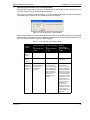
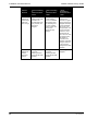
Document Conventions
The following typographic conventions are used in this document.
Doc. 13972_03
Convention
Description
Bold
Used to denote: emphasis
Used for names of menus, menu options, toolbar buttons
Italics
Used to denote: references to other parts of this document or other documents. Used for the result of an
action
i
Installation and User Manual
ADPRO FastTrace-R by Xtralis
The following icons are used in this document
Convention
Description
Caution: This icon is used to indicate that there is a danger to equipment. The danger could be loss of data,
physical damage, or permanent corruption of configuration details.
Warning: This icon is used to indicate that there is a danger of electric shock. This may lead to death or
permanent injury.
Warning: This icon is used to indicate that there is a danger of inhaling dangerous substances. This may
lead to death or permanent injury.
Tradename statement
ADPRO is a registered trademark of Xtralis AG Pty Ltd.
Lightning or Related Voltage Surges
Damage or malfunction caused by lightning or related voltage surges may be excluded from the manufacturer’s warranty at the
manufacturer’s discretion.
Safety Procedures
Installations in the United States of America and Canada
For systems installed in the United States of America and Canada the following requirement is applicable:
All equipment installations are required to be in accordance with the National Electrical Code (NEC) ANSI/NFPA 70 and the Canadian
Electrical Code (CEC) Part 1, CAN/CSA C22.1.
If the power cord is not supplied with the ADPRO XXXProduct NameXXX, select the proper power cord according to your local national
electricity code.
USA: use a UL listed type SVT or SJT detachable power cord.
Canada: use a CSA certified detachable power cord.
Radio Interference
The ADPRO FastTrace-R complies with Part 15 of the FCC Rules. Operation is subject to the following two conditions: (1) This device may
not cause harmful interference, and (2) this device must accept any interference received, including interference that may cause undesired
operation.
The ADPRO FastTrace-R complies with the electromagnetic emission limit requirements of AS/NZS CISPR22 and EN55022 Class A. In a
domestic environment this product may cause radio interference in which case the user may be required to take adequate measures.
Internal Lithium Battery
Caution:
The ADPRO FastTrace-R contains an internal lithium battery.
There is danger of explosion if the battery is incorrectly replaced.
The battery is not user replaceable and can only be replaced by Xtralis or their Authorised Service Representative.
Compliance of Power Cord
Caution:
If the power cord supplied with the ADPRO FastTrace-R is not suitable for your local power connection, do not modify
the cord. Please purchase a power cord that has the safety approvals appropriate for your country.
Connection to Other Equipment
Caution:
ii
All interface ports on the ADPRO FastTrace-R must be only connected to other equipment or systems that are Safety
Extra Low Voltage (SELV) rated. Failure to do so will invalidate the electrical safety approval and may cause injury or
loss of life
Doc. 13972_03
ADPRO FastTrace-R by Xtralis
Installation and User Manual
Contact Us
The Americas +1 781 740 2223 Asia +852 2916 8894 Australia and New Zealand +61 3 9936 7000
Continental Europe +32 56 24 19 51 UK and the Middle East +44 1442 242 330
www.xtralis.com
Doc. 13972_03
iii
Installation and User Manual
ADPRO FastTrace-R by Xtralis
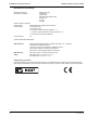
Declaration of Conformity
Manufacturer's Name:
Manufacturer's Address:
Xtralis AG Pty Ltd
4 North Drive,
Virginia Park
236-262 East Boundary Road
Bentleigh East
VIC 3165
Australia.
declares, that the product(s):
Product Name:
Model Number:
ADPRO FastTrace-R Video Security System
AFT-5020-X-Y-D-R
AFT-5010-X-Y-D-R
X = Number of Hard Disk Drives between 1 - 4.
Y = Number of Video Compression Engines between 1 - 4.
D = Down-the-Coax Telemetry Module
Product Options:
All
meet the Standards detailed below.
EMC Emissions
EN55022:1998 (CISPR 22:1997) / AS/NZS 3548:1995 + A1, A2 Class A
Conducted and radiated emissions.
FCC Part 15 Class A Conducted and radiated emissions.
EN 61000-3-2:1995 Current harmonic emissions.
EN 61000-3-3:1995 Voltage fluctuations and flicker.
EMC Immunity
EN 50130-4:1995 +A1 Alarm systems immunity.
Safety
EN 60950:1992 +A1, A2, A3, A4, + A11
IEC 60950:1991 +A1, A2, A3, + A4
Supplementary Information
The products listed comply with the requirements of the Low Voltage Directive 73/23/EEC (where applicable) and the
EMC Directive 89/336/EEC and carries the CE marking accordingly. The products were tested in a typical configuration.
iv
Doc. 13972_03
ADPRO FastTrace-R by Xtralis
Installation and User Manual
Contents
1
Introduction ...............................................................................................................................1
2
FastTrace-R Setup Instructions ...............................................................................................3
2.1
Physical Location ...........................................................................................................3
2.2
General Power Requirements ........................................................................................3
2.2.1
Power Conditioners and Surge Arresters ...........................................................4
2.2.2
Interference Caused by Ground Loops ..............................................................4
2.3
System Wiring Considerations ......................................................................................4
2.3.1
Electromagnetic Compatibility (EMC) Issues and Instructions ...........................4
2.3.2
Static Discharge .................................................................................................5
2.3.3
Grounding Requirements ...................................................................................5
2.4
Unpacking the FastTrace-R ...........................................................................................6
2.5
Mounting the FastTrace-R ..............................................................................................7
2.5.1
Rack Mounting ....................................................................................................7
2.6
Setting the Video Standard ............................................................................................7
2.7
Setting up the PC ............................................................................................................8
2.7.1
Logging onto Windows .......................................................................................8
2.7.2
Removing Previous Versions of Software ..........................................................8
2.7.3
Configuring the PC for Ethernet Connection ......................................................9
2.7.4
Configuring the PC for Serial Connection ......................................................... 10
2.7.5
Installing VideoCentral Lite Software ................................................................ 15
2.7.6
Starting VideoCentral Lite for the First Time .................................................... 18
2.8
FastTrace-R Configuration ........................................................................................... 19
2.8.1
Powering Up the FastTrace-R .......................................................................... 20
2.9
Connecting to the FastTrace-R for the First Time ..................................................... 20
2.10 Adding a New Site ......................................................................................................... 23
2.11 Testing the FastTrace-R Installation ........................................................................... 24
2.12 Notes and Troubleshooting Tips ................................................................................. 25
2.12.1 Setting the Date and Time ................................................................................ 25
2.12.2 Front Panel LED ............................................................................................... 25
2.13 FastTrace-R Connection Details Lost ......................................................................... 25
2.14 Firewall Configuration .................................................................................................. 26
3
FastTrace-R Connectors ........................................................................................................ 27
3.1
Power Connection ........................................................................................................ 28
3.2
Connecting Communication Devices ......................................................................... 28
3.2.1
COMMS 1 ......................................................................................................... 28
3.2.2
COMMS 2 ......................................................................................................... 29
3.2.3
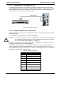
Connecting to a Modem or TA .......................................................................... 30
3.2.4
Network (Ethernet) Connection ........................................................................ 30
3.3
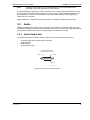
Audio .............................................................................................................................. 31
3.3.1
Audio Switch Port ............................................................................................. 31
3.3.2
Audio Screw Terminal Connector ..................................................................... 32
3.3.3
Audio Configuration .......................................................................................... 33
3.3.4
Zoned Audio ..................................................................................................... 34
3.4
Video Input Connections .............................................................................................. 35
Doc. 13972_03
Installation and User Manual
3.4.1
ADPRO FastTrace-R by Xtralis
Video Input Requirements ................................................................................ 36
3.5
Video Output ................................................................................................................. 37
3.6
Configuration Switches ................................................................................................ 37
3.7
Alarm Inputs .................................................................................................................. 39
3.7.1
Driving the Alarm Inputs ................................................................................... 40
3.8
Control Outputs ............................................................................................................ 42
3.8.1
Connecting to the Control Outputs ................................................................... 43
3.9
PTZ Connection ............................................................................................................ 43
3.9.1
PTZ Port Setup ................................................................................................. 45
3.10 General Purpose Serial Ports ...................................................................................... 46
3.11 Data Connection ........................................................................................................... 47
3.12 Connecting to the General I/O ..................................................................................... 48
3.12.1 Export Evidence - Pin 1 .................................................................................... 48
3.12.2 Access/Secure Input - Pin 3 ............................................................................. 48
3.12.3 Clock Synchronise - Pin 5 ................................................................................ 49
3.12.4 Push to Talk - Pin 7 .......................................................................................... 49
3.12.5 Mode Select Input - Pin 9 ................................................................................. 49
3.12.6 Fault Relay ....................................................................................................... 49
3.12.7 General Alarm Relay Output ............................................................................ 49
3.13 Powering Up the FastTrace-R ...................................................................................... 50
4
Programming FastTrace-R ..................................................................................................... 51
4.1
Programming Checklist ............................................................................................... 51
4.2
Setting the Operational Parameters ............................................................................ 51
4.2.1
Setting the Network Connection ....................................................................... 51
4.2.2
Setting the Telephone Connection ................................................................... 51
4.3
Entering the FastTrace-R Setup Screen ..................................................................... 52
4.3.1
Saving a Configuration to File .......................................................................... 54
4.3.2
Loading a Configuration from File .................................................................... 54
4.3.3
Site Details ....................................................................................................... 55
4.3.4
Date/Time Settings ........................................................................................... 56
4.3.5
Licensing .......................................................................................................... 59
4.3.6
Communications ............................................................................................... 60
4.3.7
Connected Equipment ...................................................................................... 69
4.3.8
Cameras ........................................................................................................... 70
4.3.9
Monitor ............................................................................................................. 77
4.3.10 Transaction Devices ......................................................................................... 77
4.3.11 Transparent Data Port ...................................................................................... 78
4.3.12 Alarm Inputs ..................................................................................................... 80
4.3.13 Presidium Inputs ............................................................................................... 81
4.3.14 Control Outputs ................................................................................................ 83
4.3.15 Audio ................................................................................................................ 85
4.3.16 Arming / Disarming ........................................................................................... 86
4.3.17 Operational Behaviour ...................................................................................... 87
4.3.18 Operational Modes ........................................................................................... 89
4.3.19 Audio Behaviour ............................................................................................... 91
4.3.20 Camera Behaviour ........................................................................................... 92
4.3.21 Multi-Screen Live Behaviour ............................................................................ 99
4.3.22 Entry/Exit Behaviour ....................................................................................... 103
4.3.23 Maintenance ................................................................................................... 104
Doc. 13972_03
ADPRO FastTrace-R by Xtralis
5
Installation and User Manual
Event Log ............................................................................................................................... 107
5.1
Save the Event Log ..................................................................................................... 108
5.2
Severity and Visibility Levels ..................................................................................... 109
6
FastTrace-R Impounding ...................................................................................................... 115
7
Testing the FastTrace-R System ......................................................................................... 117
7.1
8
Upgrading the FastTrace-R Software .................................................................................. 119
8.1
9
Installation and Testing Checklist ............................................................................. 117
Software Upgrade Process ........................................................................................ 119
Specifications ........................................................................................................................ 121
9.1
FastTrace-R ................................................................................................................. 121
9.2
VideoCentral Lite Minimum Specifications .............................................................. 125
List of Figures
Figure 1: Typical FastTrace-R Application .............................................................................................2
Figure 2: FastTrace-R Grounding Requirements ...................................................................................6
Figure 3: FastTrace-R Front Panel for 19 inch Rack Mount Models ......................................................7
Figure 4: Typical Setup Connections - Ethernet or Serial ......................................................................8
Figure 5: Internet Protocol......................................................................................................................9
Figure 6: System Properties................................................................................................................. 10
Figure 7: Device Manager .................................................................................................................... 10
Figure 8: COM Port Settings ................................................................................................................ 11
Figure 9: Phone and Modem Options .................................................................................................. 12
Figure 10: Install New Modem.............................................................................................................. 12
Figure 11: Select Modem Driver from Disk .......................................................................................... 13
Figure 12: Install from Disk................................................................................................................... 13
Figure 13: Select Modem COM Port .................................................................................................... 14
Figure 14: Installation Warning............................................................................................................. 14
Figure 15: Null-Modem Wiring.............................................................................................................. 15
Figure 16: Installation Screen............................................................................................................... 15
Figure 17: Setup Wizard Introduction Screen ...................................................................................... 16
Figure 18: Installation Location ............................................................................................................ 16
Figure 19: Transmitter Alarm Management.......................................................................................... 17
Figure 20: Communication Devices ..................................................................................................... 17
Figure 21: Setup Complete .................................................................................................................. 18
Figure 22: Dongle Required ................................................................................................................. 18
Figure 23: Default Ethernet Site Configuration..................................................................................... 19
Figure 24: Default Serial Site Configuration......................................................................................... 19
Figure 25: Connect To Site .................................................................................................................. 21
Figure 26: VideoCentral User Interface................................................................................................ 21
Figure 27: Installer Menu Button .......................................................................................................... 22
Figure 28: FastTrace-R User Settings.................................................................................................. 23
Figure 29: Configure a New Site .......................................................................................................... 24
Figure 30: Camera List......................................................................................................................... 24
Figure 31: FastTrace-R Connections ................................................................................................... 27
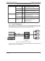
Figure 32: Comm1 Pin Numbers.......................................................................................................... 28
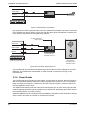
Figure 33: Modem Connection............................................................................................................. 30
Doc. 13972_03
Installation and User Manual
ADPRO FastTrace-R by Xtralis
Figure 34: Audio D-Connector Pinouts ................................................................................................ 31
Figure 35: Audio Connector Pinouts .................................................................................................... 32
Figure 36: Audio Configuration with Amplifier ...................................................................................... 33
Figure 37: Microphone Connection...................................................................................................... 34
Figure 38: FastTrace-R with Intercom.................................................................................................. 34
Figure 39: Zoned Audio Configuration ................................................................................................. 35
Figure 40: Video Configuration ............................................................................................................ 36
Figure 41: Video Output Configuration................................................................................................. 37
Figure 42: Alarm Input Configuration ................................................................................................... 40
Figure 43: Alarm Connector Pinouts.................................................................................................... 41
Figure 44: External Sensor Wiring Circuits .......................................................................................... 42
Figure 45: Pinouts for Control Output Connectors............................................................................... 43
Figure 46: External Relay - Typical Output Circuit ............................................................................... 43
Figure 47: Pin Numbering of the PTZ Port........................................................................................... 44
Figure 48: Typical RS485 Connection to Multiple Telemetry Stations ................................................. 44
Figure 49: Typical PTZ Configuration .................................................................................................. 45
Figure 50: RS485 PTZ Port Connections to a Telemetry Station ........................................................ 46
Figure 51: Pin Numbering of the Serial Port ........................................................................................ 46
Figure 52: Typical Configuration with ATM/EPOS ............................................................................... 47
Figure 53: Pin Numbering of the Data Port .......................................................................................... 48
Figure 54: Pinouts for General I/O Connector...................................................................................... 48
Figure 55: Installer Menu Icon.............................................................................................................. 52
Figure 56: FastTrace-R User Settings ................................................................................................. 53
Figure 57: TCP IP Settings .................................................................................................................. 54
Figure 58: Incompatible User Settings File .......................................................................................... 54
Figure 59: Site Details Menu................................................................................................................ 55
Figure 60: Date/Time Settings Menu ................................................................................................... 56
Figure 61: Set FastTrace-R Time and Date......................................................................................... 57
Figure 62: Licensing Settings............................................................................................................... 59
Figure 63: Communications Menu ....................................................................................................... 60
Figure 64: Ethernet Settings ................................................................................................................ 61
Figure 65: Serial Communication Port Settings Menu ......................................................................... 63
Figure 66: Advanced Serial Communications...................................................................................... 66
Figure 67: Advanced Communication Properties................................................................................. 67
Figure 68: Connected Equipment Menu .............................................................................................. 69
Figure 69: Cameras Menu ................................................................................................................... 71
Figure 70: Camera Settings - General Tab .......................................................................................... 72
Figure 71: Camera Settings - PTZ ....................................................................................................... 73
Figure 72: Alarm Preset Warning......................................................................................................... 74
Figure 73: Camera Settings - Activity Detection Tab ........................................................................... 75
Figure 74: Activity Detection Mask....................................................................................................... 76
Figure 75: Monitor Menu...................................................................................................................... 77
Figure 76: Transparent Data Port Menu .............................................................................................. 78
Figure 77: Transparent Data Port Settings .......................................................................................... 79
Figure 78: Unallocated Icon ................................................................................................................. 80
Figure 79: Alarm Contacts List............................................................................................................. 80
Figure 80: Unallocated Icon ................................................................................................................. 82
Figure 81: Presidium Inputs List........................................................................................................... 82
Figure 82: Presidium Input Settings ..................................................................................................... 83
Figure 83: Control Output Settings Menu............................................................................................. 84
Figure 84: Audio Settings..................................................................................................................... 85
Figure 85: Operational Behaviour Menu .............................................................................................. 87
Figure 86: Operational Modes Menu.................................................................................................... 89
Figure 87: Changing Modes Via an Input............................................................................................. 90
Figure 88: Changing Modes Via Calendar ........................................................................................... 90
Figure 89: Audio Behaviour Settings.................................................................................................... 91
Figure 90: Camera Behaviour Menu.................................................................................................... 92
Doc. 13972_03
ADPRO FastTrace-R by Xtralis
Installation and User Manual
Figure 91: Video Capture Settings ....................................................................................................... 93
Figure 92: Video Capture Settings ....................................................................................................... 93
Figure 93: Event Trigger Settings......................................................................................................... 95
Figure 94: Event Input Settings ............................................................................................................ 95
Figure 95: Event Input Settings - Programming Error .......................................................................... 96
Figure 96: Event Input Settings Warning.............................................................................................. 96
Figure 97: Event Input Settings ............................................................................................................ 97
Figure 98: Event Response Tab........................................................................................................... 97
Figure 99: Multi-Screen Live Behaviour Menu ..................................................................................... 99
Figure 100: Guard Tour Camera List ................................................................................................. 100
Figure 101: Selectable Multi-Screen Settings .................................................................................... 100
Figure 102: Multi-Screen Settings Buttons......................................................................................... 101
Figure 103: Selectable Multi-Screen Settings .................................................................................... 102
Figure 104: Entry Exit Behaviour........................................................................................................ 103
Figure 105: Maintenance Menu.......................................................................................................... 104
Figure 106: Temperature Management.............................................................................................. 104
Figure 107: Zone Isolate Reminder Settings...................................................................................... 105
Figure 108: Licence Information Message ......................................................................................... 106
Figure 109: Perform a Search Button................................................................................................. 107
Figure 110: Log Search Dialog........................................................................................................... 107
Figure 111: Save Event or Logs button.............................................................................................. 108
Figure 112: Save As Dialog................................................................................................................ 108
Figure 113: Log File Displayed in Excel ............................................................................................. 108
Figure 114: Upgrade Icon................................................................................................................... 119
Figure 115: Upgrade Dialog ............................................................................................................... 119
Figure 116: 'Flying Papers' Pop-up .................................................................................................... 120
Figure 117: Site Actions Icon ............................................................................................................. 120
Figure 118: Site Details Tab............................................................................................................... 120
List of Tables
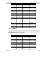
Table 1: Firewall Ports.......................................................................................................................... 26
Table 2: Comm Port 1 Connection ....................................................................................................... 28
Table 3: Comm Port 2 Connection ....................................................................................................... 29
Table 4: Ethernet Connection............................................................................................................... 30
Table 5: Audio Switcher Connections .................................................................................................. 32
Table 6: Audio Screw Terminal Connector........................................................................................... 33
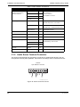
Table 7: DIP Switch Configuration ....................................................................................................... 38
Table 8: PTZ Port Connections ............................................................................................................ 44
Table 9: General Purpose Serial Port Connections ............................................................................. 47
Table 10: Data Port Connections ......................................................................................................... 48
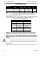
Table 11: Time Change Compatibility Matrix ....................................................................................... 57
Table 12: Capture Settings defaults ..................................................................................................... 94
Table 13: Quality Value versus Resolution .......................................................................................... 94
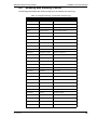
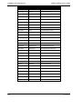
Table 14: Assigned Severity of FastTrace-R Event Logs................................................................... 109
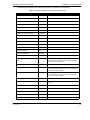
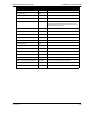
Table 15: Assigned Visibility of FastTrace-R Event Logs................................................................... 111
Doc. 13972_03
Installation and User Manual
ADPRO FastTrace-R by Xtralis
Doc. 13972_03
ADPRO FastTrace-R by Xtralis
1
Installation and User Manual
Introduction
ADPRO FastTrace-R by Xtralis is an advanced, high performance digital video and audio
recorder optimised for remote search and playback. Available in a number of models with 10 or
20 video inputs, FastTrace-R provides outstanding transmission speed and picture quality for
remote security and surveillance applications where secure, event-driven recording from multiple
cameras onto digital data storage disks is required. In addition, FastTrace-R can provide multiuser network access or dedicated telephone line connection for searching, retrieval and
transmission of stored data from a remote monitoring site.
When compared to a standard ADPRO FastTrace by Xtralis transmitter that can dial-out to a
Central Monitoring Site (CMS) on certain alarm or pre-set conditions, a number of differences are
apparent due to the FastTrace-R application environment, where dial-out is not a requirement.
Instead, the FastTrace-R will retain (queue) up to 100 system and fault alarms that will be
downloaded to VideoCentral when a manual connection is made. These system and fault alarms
are reset on a power failure. Other differences are:
•
•
•
•
•
•
•
•
•
•
•
The Arm/Disarm option is not required.
“Camera view style” is “Live” only (alarm and Presidium inputs).
The “Call list configuration” is not required.
The ability to use an “alarm input as an Arm/Disarm Input” is not required.
The ability to “Activate Control Output while unit is armed” is not required.
The ability to “Activate Control Output when sensors are active” is not required.
The option to “Dial Out on event for each camera” is not required.
The Entry/Exit Path option is not required.
The SitePulse option is not required.
There is no requirement for the duress alarm option.
There are no quad alarms required.
FastTrace-R can be installed to be fully compatible with the British Standard, BS8418. This
standard applies to remotely monitored video verification systems, and is mandatory in the UK to
receive police response to intrusions. It specifies superior quality equipment, best practice
installation and monitoring requirements that will ensure long term, high performance operation
for the end user.
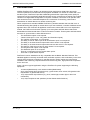
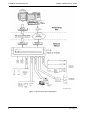
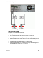
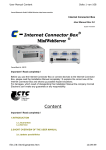
Figure 1 shows a typical application using the FastTrace-R system supporting the following
equipment:
•
•
•
•
Doc. 13972_03
10 camera (Model 5010) or 20 camera models (Model 5020)
20 (or 30) external alarm input devices (e.g. panic button, door switch, PIR (passive infrared) detector or glass break switch)
10 (or 20) external output devices (e.g. siren, strobe light, outdoor light or door lock
mechanism)
10 (or 20) microphones and speakers (via the VM22A Audio Switcher)
1
Installation and User Manual
ADPRO FastTrace-R by Xtralis
Figure 1: Typical FastTrace-R Application
2
Doc. 13972_03
ADPRO FastTrace-R by Xtralis
2
Installation and User Manual
FastTrace-R Setup Instructions
This chapter contains instructions to setup the FastTrace-R.
2.1
Physical Location
The location within the protected premises of the FastTrace-R should be considered carefully
and the following notes are provided for guidance.
•
Physical Security - The FastTrace-R should be located where it will remain secure under
all conditions, even when the premises are open or occupied. The safest place would be a
room (or cabinet) with a lockable door. It should not be visible from outside the premises
and not be accessible to occupant or visitor tampering.
Caution:
•
•
System Wiring - Ideally, the FastTrace-R’s position will be close to the centre of the site
wiring. Excessive cable runs will increase the installation cost, cause voltage drops,
degrade signals, and offer greater scope for EMI/RFI (electrical interference) induced faults,
tampers, and false alarms. Wiring considerations should include the following:
The largest wiring requirement is the coaxial camera cabling and the wiring to the
alarm input and output devices
Mains power
The system requires at least one video camera and associated coaxial cabling for
system setup
Environment - Choose an inside location that is cool and dry. Do not mount the FastTraceR anywhere near machinery that generates heat, toxic fumes and dust. Do not mount the
FastTrace-R in close proximity to sources of radio frequency or other electromagnetic
radiation. These include radio transmitters (both fixed and portable), electric motors,
refrigeration or air conditioning systems and high power or multiphase switching equipment.
Caution:
2.2
FastTrace-R equipment must be used only in an INDOOR environment.
FastTrace-R should be given time to adjust to room temperature before it is turned
on. The hard disk storage devices have a defined operational temperature range of
0 to 40 degrees Celsius. It is recommended the FastTrace-R be given a period of 24
hours to acclimatise.
General Power Requirements
Any AC supply connected to the FastTrace-R should be:
•
•
•
Provided from a reliable electric supply company - typically this means that the power is not
disconnected (or lost) for any more than eight hours at a time in any 36 hour period and
infrequently in a single year.
Provided from a supply bus within the protected premises that is not isolated at night (or out
of hours) or time switched. The supply should be free from voltage spikes or current surges
(connected to high power switching equipment or electric motors).
Supplied directly to the FastTrace-R via circuits that cannot be switched off, intentionally or
accidentally.
Always consider local regulations, standards, and guidelines for mains power connected
systems.
Doc 13972_03
3
Installation and User Manual
Caution:
ADPRO FastTrace-R by Xtralis
The FastTrace-R is a Class 1 electrical product and must always be connected to a
grounded power outlet. Always ensure that FastTrace-R is installed adjacent to a
grounded power outlet.
2.2.1 Power Conditioners and Surge Arresters
The use of an Uninterruptible Power Supply (UPS) should be considered in situations where the
mains power is unreliable. A good UPS has the ability to remove interference, sags, and power
surges that can cause false alarms, equipment failure or even terminal damage. UPS are used
effectively on all major computer installations and the microelectronics used in many video and
alarm systems (including FastTrace-R) are similar, both in their functionality, and their
susceptibility to ‘dirty’ mains power.
Power line conditioners or surge arresters can help prevent mains distortion of voltage, current,
and frequency caused by load switching, large electric motors, and lightning. These distortions
can cause unreliable operation, false alarms, and equipment failure, damage or even total
destruction.
2.2.2 Interference Caused by Ground Loops
In some installations, where cameras or monitors are located at a distance from the FastTrace-R
rack, considerable ground loop currents can be generated and may cause interference.
Supplying power to different components of the FastTrace-R system may also cause ground loop
currents. For example, cameras, monitors and the FastTrace-R chassis may receive power from
different phases of a multi-phase supply. Wherever possible, source power to all components of
the system from a common phase of the supply.
Where ground loop currents cause a problem in a FastTrace-R installation, the installer may
reduce the effect by installing a video isolation transformer on each video channel affected.
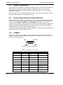
2.3
System Wiring Considerations
2.3.1 Electromagnetic Compatibility (EMC) Issues and
Instructions
When a FastTrace-R system is installed in accordance with the recommendations and
procedures in this manual, it will meet the EMC requirements of:
•
•
EN 55022 / AS3548 Class A, and FCC Part 15 Class A digital devices in respect to
emissions, and
EN 50130-4 Alarm Systems Immunity.
To ensure EMC compliance for your system installation, make sure of the following:
•
•
•
4
CAT-5 Unshielded Twisted Pair (UTP) Data Cable is used for the Network port connection,
RG-59 coaxial 75 ohm Video cable is used for all composite video connections and the
cables are terminated with 75 ohm BNC connectors, and
Where possible, all cables should be shielded (single or dual) twisted pair and the shield
itself, along with the associated drain wire, terminated at the FastTrace-R with a connection
to the chassis.
Doc 13972_03
ADPRO FastTrace-R by Xtralis
Note:
Installation and User Manual
The foil used in some shielded cable is only insulated on one side. Always check
the foil shield with an ohm-meter and make sure that the conductive side is in
contact with shield termination recommendations in this manual.
FCC Advice for Installers and Users in the United States
FastTrace-R equipment has been tested and found to comply with the limits for a Class A digital
device, pursuant to part 15 of the FCC Rules. These limits are designed to provide reasonable
protection against harmful interference in a residential installation. This equipment generates,
uses and can radiate radio frequency energy and, if not installed and used in accordance with
the instructions, may cause harmful interference to radio communications. However, there is no
guarantee that interference will not occur in a particular installation.
If this equipment does cause harmful interference to radio or television reception, which can be
determined by turning the equipment off and on, the user is encouraged to try to correct the
interference by one or more of the following measures:
•
•
•
•
Reorient or relocate the receiving antenna
Increase the separation between the equipment and receiver
Connect the equipment into an outlet on a circuit different from that to which the receiver is
connected
Consult the dealer (or installer) or an experienced radio/TV technician for help
Caution:
Changes or modifications not expressly approved by Xtralis could void the user's
authority to operate this equipment.
2.3.2 Static Discharge
The FastTrace-R system components contain electrical parts that are susceptible to damage
from static discharge. Static voltages of one to thirty kilovolts are common in unprotected
environments.
When installing or servicing the FastTrace-R equipment, it is advisable to observe the following
standard precautions for handling electronic assemblies to reduce the risk of component
damage:
•
•
•
Minimise handling of electronic assemblies and components.
Transport, temporarily arrange and store electronic components in recognised anti-static
containers.
Discharge any static voltage from your body before handling electronic components or wear
a grounded, Safety-Standard Approved, anti-static wrist strap while handling components.
Avoid handling electronic components in areas which have a floor or work-surface capable of
generating a static charge.
2.3.3 Grounding Requirements
The product safety standard that FastTrace-R is assessed to (IEC 60950-1) defines metallic
video and/or audio cables connected between separate buildings, or between outdoor antennas
and buildings, as Cable Distribution Systems and requires that products connected to these
cables have a permanent connection to protective earth.
As the typical installations that FastTrace-R is used in has video and / or audio cables connected
between separate buildings, it is required to have this permanent connection to protective earth.
FastTrace-R has a permanent earth connection point fitted to the lower right hand side of the rear
panel.
Doc 13972_03
5
Installation and User Manual
ADPRO FastTrace-R by Xtralis
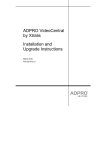
This permanent earth connection point is an M4 tapped insert on the metalwork and is supplied
with a screw and washer as shown below.
Figure 2: FastTrace-R Grounding Requirements
Connect this earth point to a protective earth point in the system installation using 2.5 mm 2 wire
(minimum) and suitable ring terminals.
The installation protective earth point must be installed in accordance with local electrical
installation codes and requirements.
2.4
Unpacking the FastTrace-R
When you first receive the FastTrace-R it is important to check that:
•
•
You have received the equipment that you ordered.
The box contains all the necessary components.
After unpacking the FastTrace-R, carefully check for any sign of damage. Any damage should be
reported before installation to your supplier or to Xtralis directly. Check that the FastTrace-R
packing carton contains the following items:
1
1
1
1
1
4 or 6
1
FastTrace-R chassis
DVD containing VideoCentral software
Installation and User Manual
Crossover Ethernet cable
9-way screw terminal plug
15-way screw terminal plug (Model 5010=4, Model 5020=6)
IEC power cord
The DVD contains software that must be loaded onto a PC or laptop in order to program the
system.
Note:
6
The FastTrace-R Installation and User Manual is also available in PDF format on
the DVD.
Doc 13972_03
ADPRO FastTrace-R by Xtralis
Installation and User Manual
To complete FastTrace-R installation, you may need:
•
•
•
Null modem cable
Camera and coax cable
External alarm switches or other devices
•
PC or Laptop running Microsoft Windows 2000 Professional or Windows XP
Professional, with an Ethernet Port or a serial port and a DVD drive.
®
2.5
®
®
Mounting the FastTrace-R
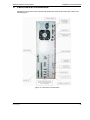
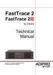
2.5.1 Rack Mounting
The FastTrace-R models are housed in a 3 U high chassis for mounting in a 19" rack with a
layout as shown in the following figure. To ensure long term electronic equipment reliability, it is
advisable to:
•
•
•
mount the unit clear of other equipment that can dissipate large amounts of heat,
ensure adequate air flow (either convective or forced) between the unit and its
surroundings, and
ensure that the fan opening on the rear panel is not blocked by other equipment.
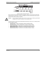
Figure 3: FastTrace-R Front Panel for 19 inch Rack Mount Models
2.6
Setting the Video Standard
FastTrace-R can be set to operate using either PAL (CCIR) or NTSC (RS170) video standards.
Once a standard has been selected, all video inputs and the monitor output (composite video)
will be configured to use the same standard.
To set the required video standard, use the Configuration DIP switch on the rear panel.
Configuration Switch # 10
Note:
Doc 13972_03
ON = NTSC
OFF = PAL
To be configured correctly, this switch must be set before power on.
7
Installation and User Manual
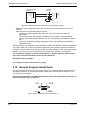
2.7
ADPRO FastTrace-R by Xtralis
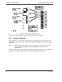
Setting up the PC
To set up the FastTrace-R for operation, it must be connected to a PC installed with the latest
version of VideoCentral Lite or Gold. Contact your ADPRO supplier or sales office for details.
Connection to the FastTrace-R may be via an Ethernet crossover cable (supplied), via the
Ethernet port on the rear of the FastTrace-R, or via a null modem cable (not supplied), via the
Comms 2 port on the rear of the FastTrace-R.
Figure 4: Typical Setup Connections - Ethernet or Serial
The following sequence briefly describes the install/upgrade process for VideoCentral Lite. For
detailed instructions of the VideoCentral Upgrade process, please refer to the VideoCentral
Administrator Manual (Part No: 201817).
Note:
To install or upgrade VideoCentral, Administrator level access will generally be
required. Power User level access may be used, but depending on the limitations
placed on Windows from a security perspective, this may not be successful.
2.7.1 Logging onto Windows
When using Windows 2000 Professional or Windows XP Professional, log on as a Power User or
an Administrator.
2.7.2 Removing Previous Versions of Software
If it is necessary to remove previous versions of ADPRO software installed on your PC, please
refer to the VideoCentral Administrator Manual for details.
Note:
8
Please ensure that the database information associated with that installation is not
destroyed, if it is important. Refer to the VideoCentral Administrator Manual for
details.
Doc 13972_03
ADPRO FastTrace-R by Xtralis
Installation and User Manual
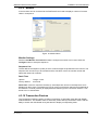
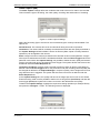
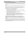
2.7.3 Configuring the PC for Ethernet Connection
A crossover Category 5 Ethernet cable is supplied for connection between the PC’s network port
and the FastTrace-R Ethernet (Network) port. This cable must be connected between the PC
and FastTrace-R prior to powering on the FastTrace-R.
The (factory) TCP/IP network address for the FastTrace-R is: 192.168.1.1
The (factory) subnet mask address is 255.255.255.0
For the PC to be able to successfully connect to the FastTrace-R, the PC IP settings must be
modified to a class C address.
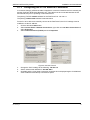
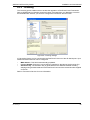
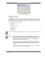
1.
2.
3.
Click the Windows Start button.
Select Control Panel / Network Connections, right click on Local Area Connection and
select Properties.
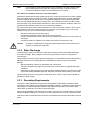
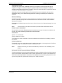
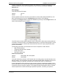
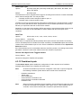
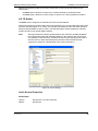
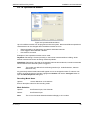
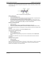
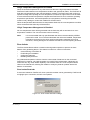
Select Internet Protocol (TCP/IP) and click Properties.
Figure 5: Internet Protocol
4.
5.
6.
Doc 13972_03
Change the PC IP settings to the following: 192.168.1.2
Set the subnet mask address to: 255.255.255.0
Click OK, and the Local Area Connection Properties box is displayed again. Click OK and
close the Network and Dial up Connections panel.
9
Installation and User Manual
ADPRO FastTrace-R by Xtralis
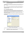
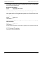
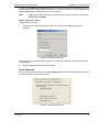
2.7.4 Configuring the PC for Serial Connection
Note:
The following procedure is only required if you have a null modem cable and do not
intend to use the crossover ethernet cable to connect to the FastTrace-R. (Refer to
Section 2 - Null-Modem Cable Wiring for wiring details for the null modem cable).
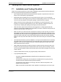
The serial comms (COM) port on the PC must be configured for operation as follows:
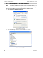
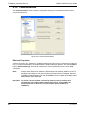
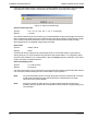
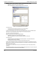
1.
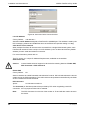
Select Control Panel / System / Hardware tab.
Figure 6: System Properties
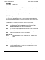
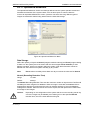
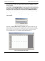
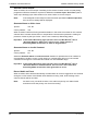
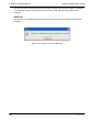
2.
Select Device Manager and expand the Ports (COM & LPT) selection.
Figure 7: Device Manager
10
Doc 13972_03
ADPRO FastTrace-R by Xtralis
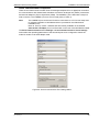
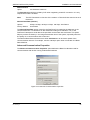
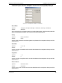
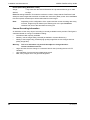
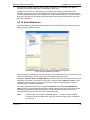
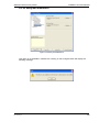
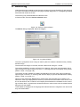
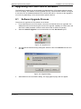
3.
Installation and User Manual
Double click on the required communications port (COM1 or COM2).
Figure 8: COM Port Settings
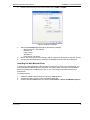
4.
5.
6.
Select the Port Settings tab and enter the following settings:
Bits per second = 115,200 bps
Data bits = 8
Parity = none
Stop bits = 1
Flow control = hardware
Ensure the FastTrace-R is free-standing with no obstruction to airflow (cooling fan at rear).
Connect the cable between the FastTrace-R COMMS 2 port and the PC's serial port.
Installing the Null Modem Driver
If you are using the Null-Modem cable connection method to connect to the FastTrace-R, you
must install the Null-Modem driver in Windows. This step is NOT necessary if a Null-Modem
driver has already been installed on the PC, or if you are using an Ethernet connection to
FastTrace-R.
To install this driver:
1.
2.
3.
Doc 13972_03
Insert the ADPRO VideoCentral Lite CD in the CDROM Drive.
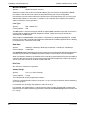
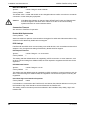
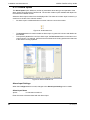
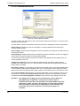
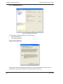
If necessary enter an Area code in the Dialing Rules tab.
Click the Windows Start button and select: Control Panel / Phone and Modem Options.
11
Installation and User Manual
ADPRO FastTrace-R by Xtralis
Figure 9: Phone and Modem Options
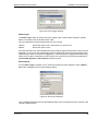
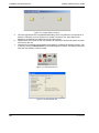
4.
Click on the Modems tab and select the Add button.
Figure 10: Install New Modem
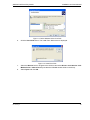
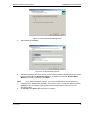
5.
12
When the Install New Modem dialog box is displayed, click the Don't detect my modem, I
will select it from a list checkbox, then click Next.
Doc 13972_03
ADPRO FastTrace-R by Xtralis
Installation and User Manual
Figure 11: Select Modem Driver from Disk
6.
Click the Have Disk button. The Install From Disk screen is displayed.
Figure 12: Install from Disk
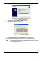
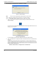
7.
8.
Doc 13972_03
Select the Browse button, navigate to the CD drive and select Drivers and Libraries / Null
Modem Driver / mdmcisc2.inf (note that the CDROM should still be in the drive).
Select Open and click OK.
13
Installation and User Manual
ADPRO FastTrace-R by Xtralis
Figure 13: Select Modem COM Port
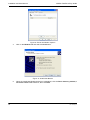
9. Click Next and select either COM1 or COM2 (but not both).
10. Click Next, the following screen will display.
Figure 14: Installation Warning
11. Select Continue Anyway and click Finish when the software has installed.
Reboot the PC to ensure the serial comms and modem driver changes become active.
Note:
14
The Null Modem driver will only allow outgoing calls from VideoCentral, preventing it
from being used to receive events.
Doc 13972_03
ADPRO FastTrace-R by Xtralis
Installation and User Manual
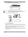
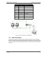
Null-modem Cable Wiring
Should it be necessary to use a null-modem cable that is longer than that supplied with the
FastTrace-R, use the diagram shown to make a longer cable.
Note:
RS232 cables should never extend past 15m (33 feet).
Figure 15: Null-Modem Wiring
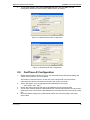
2.7.5 Installing VideoCentral Lite Software
1.
Start the PC and insert the CD into the appropriate CD drive. If the CD does not autorun,
select the AutorunEx application from the CD drive from Windows Explorer. The following
screen will appear.
Figure 16: Installation Screen
Doc 13972_03
15
Installation and User Manual
2.
ADPRO FastTrace-R by Xtralis
Select VideoCentral Lite, the following window is displayed.
Figure 17: Setup Wizard Introduction Screen
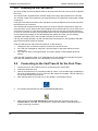
3.
4.
After checking that the version number that you are upgrading to is correct, click Next. At
any point during the installation, you can go back any number of steps by clicking Back.
Check that the location shown is where you wish to install VideoCentral. If it is correct, click
Next, otherwise browse and select the location.
Figure 18: Installation Location
Note:
16
On the next screen you MUST select the Yes option for receiving alarms otherwise
you will not be able to configure the FastTrace-R unit from VideoCentral Lite.
Doc 13972_03
ADPRO FastTrace-R by Xtralis
Installation and User Manual
Figure 19: Transmitter Alarm Management
5.
Select Yes and click Next.
Figure 20: Communication Devices
6.
Select the checkbox next to the device you are using to enable VideoCentral Lite to connect
to the FastTrace-R unit (Network Adaptor for an ethernet connection, Generic NULL
Modem for a serial connection). Click Next.
Note:
7.
8.
Doc 13972_03
If you wish to change the option, you must first DESELECT the current device.
If Generic NULL Modem was selected in the previous screen, accept the default selection
of PSTN on the Connection Types screen and the default values on the Phone Line
Checking screen.
Click Finish, then Exit and the process is complete.
17
Installation and User Manual
ADPRO FastTrace-R by Xtralis
The screen below is displayed when the installation is complete:
Figure 21: Setup Complete
Note:
The PC must be restarted before VideoCentral Lite can be used.
2.7.6 Starting VideoCentral Lite for the First Time
1.
Start the VideoCentral Lite program by double-clicking the VideoCentral icon on the
Windows desktop.
If you do not have a VideoCentral dongle (Hardware Protection Key) attached to the PC, the
following screen will appear.
Figure 22: Dongle Required
It is not necessary to have this device attached to perform the setup functions.
2.
Click on the Yes button to accept this condition and VideoCentral Lite user interface will be
displayed.
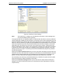
To help users with the first time setup of a FastTrace-R, a number of default settings are
used in the ADPRO VideoCentral Lite software that must match the default factory settings
found in a new FastTrace-R unit. The default settings stored in the VideoCentral Lite can be
found by using the following menu:
Database / Administration / Configure Sites / FT-R default site.
18
Doc 13972_03
ADPRO FastTrace-R by Xtralis
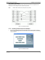
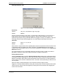
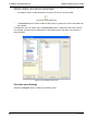
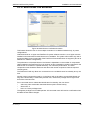
3.
Installation and User Manual
To check the defaults, select the FT-R default site entry and click Edit. The Site
Configuration details are shown with the default values, as follows:
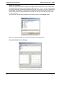
Figure 23: Default Ethernet Site Configuration
Figure 24: Default Serial Site Configuration
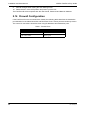
2.8
1.
FastTrace-R Configuration
Before powering the FastTrace-R unit on, check that the factory DIP-Switch settings are
correct refer to Section 3 for more details.
The location of the DIP-Switch is on the rear of the FastTrace-R unit at the bottom,
underneath the camera connections and next to the monitor connector.
2.
3.
4.
5.
Doc 13972_03
Set the DIP-Switch 10 to the appropriate video standard for the region:
(ON - NTSC, OFF - PAL).
Ensure the airflow vents into the side of the FastTrace-R unit are not blocked.
Connect the crossover Ethernet cable between the FastTrace-R Ethernet port and the PC’s
Ethernet port or the null modem cable between the Comm2 port and the PC’s serial comms
port.
Once DIP-Switch settings are verified and all cables are connected, plug in the mains
power cable.
19
Installation and User Manual
ADPRO FastTrace-R by Xtralis
2.8.1 Powering Up the FastTrace-R
The green Power and the red Status LEDs on the front panel are lit as soon as power is applied
to the unit.
The FastTrace-R is supplied with a universal input power supply that operates from 100-240V
AC, 50-60Hz. There are no switches to change based upon your particular mains power voltage
or frequency.
If the green LED fails to illuminate check that there is power available from the socket into which
the FastTrace-R is connected.
The FastTrace-R will then automatically perform a series of self-test routines which check the
microprocessor circuits. When power is first applied to the FastTrace-R unit, the red LED on the
front of the unit will be on. After approximately 60 seconds, the red LED should start switching
on, then off, every two seconds. This signifies that the unit has completed its internal checks and
is now checking the integrity of the Hard Disk Drive(s) (HDD). Once the unit successfully
completes the integrity check, the red LED will switch off, and remain off.
If at any time during operation, the red LED switches on and stays on, this signifies a fault with
the unit and technical support is required.
If the red LED does not switch off and remain off, do the following:
1.
2.
3.
Unplug all of the connectors except the power and re-power the unit.
If the red LED extinguishes, plug each connector back in and check that the red LED
remains off.
If the red LED does not extinguish after 10 minutes, please contact ADPRO technical
support.
If the red LED continues to flash for an extended period, this signifies that corruption has been
found with the database and the unit is attempting to correct the fault.
2.9
1.
2.
3.
20
Connecting to the FastTrace-R for the First Time
4.
Connect the PC to the FastTrace-R unit, via the ethernet or serial cable.
Power the FastTrace-R up.
Wait for the FastTrace-R to complete its start-up checks. The red status light will initially be
ON, then will start flashing, then go OFF once the checks are complete. This can take up to
two or three minutes from power on.
Start VideoCentral Lite from the icon on the desktop, if not already running.
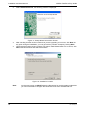
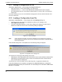
5.
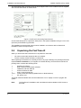
From within VideoCentral Lite click the Connect to Site button.
6.
Select the site named FT-R default site and then select the connectors type in the
Connect Via list. Click OK. You should see the Connection Status screen followed by a
screen confirming connection.
Doc 13972_03
ADPRO FastTrace-R by Xtralis
Installation and User Manual
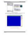
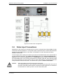
Figure 25: Connect To Site
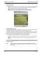
The VideoCentral User Interface screen will be displayed and if a camera has been connected,
there should be video displayed, otherwise a standard blue screen is shown.
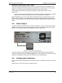
Figure 26: VideoCentral User Interface
Doc 13972_03
21
Installation and User Manual
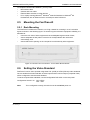
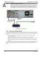
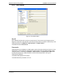
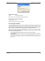
7.
ADPRO FastTrace-R by Xtralis
Go to the Connection menu and click the Installer Menu option (or click the Installer
Menu button on the Site Actions flyout).
Figure 27: Installer Menu Button
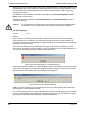
The Setup files will be downloaded from the FastTrace-R unit.
Note:
The first time the settings are accessed, it may take some time to download the
settings as the setup program is also being downloaded from the FastTrace-R unit.
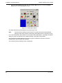
For a new FastTrace-R, the first time a user accesses the Installer Menu, a message will appear
asking the user to accept the Factory Default settings. Click Yes to this question.
Once the Factory Default Settings have been accepted, subsequent requests to enter the
Installer Menu will not display this message.
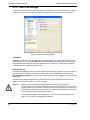
The FastTrace-R User Settings screen is displayed.
22
Doc 13972_03
ADPRO FastTrace-R by Xtralis
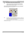
Installation and User Manual
Figure 28: FastTrace-R User Settings
Setup parameters and configuration options for the FastTrace-R can now be modified.
Refer to Section 4 - Programming FastTrace-R for details of the settings which must be defined
to use the FastTrace-R in an operational environment.
8.
Define all required FastTrace-R user settings and select the Save to FT-R button.
The modified files will be uploaded to the FastTrace-R for permanent storage and the site
will be disconnected.
Note:
The setup program will not allow invalid parameters to be saved. For example,
should you receive a message asking for a correct Ethernet Gateway address to be
entered, either enter the correct value or delete the invalid entry.
2.10 Adding a New Site
To connect to the site again, VideoCentral must be configured with a new site, which has the
Ethernet or Serial Communications properties identical to those entered at the Site Details and
Communications screens of the user settings:
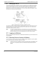
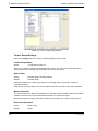
1.
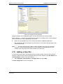
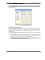
Select Database / Administration / Configure Sites and select New.
The Site Configuration screen is displayed:
Doc 13972_03
23
Installation and User Manual
ADPRO FastTrace-R by Xtralis
Figure 29: Configure a New Site
2.
3.
4.
Enter the following details for the FastTrace-R unit:
Site Id: 9 characters (max) - this is the name of the FastTrace-R unit
CMS Password: 8 characters (max)
Communications: Network
For the Network selection, enter a valid IP address for the FastTrace-R
Click OK. The configure Site dialog box is shown again. Click Close. The System
Administration options are then shown. Click Exit.
For a network connection, the PC must now have its IP Address changed to be on the same
subnet mask as the modified IP Address of the FastTrace-R (but with a different IP address).
Refer to Section 2 - Configuring the PC for Ethernet Connection for details of how to perform this.
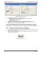
2.11 Testing the FastTrace-R Installation
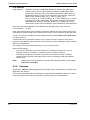
1.
2.
Reconnect to the FastTrace-R by selecting the Connect to site button, highlighting the new
site (unit name) and press OK.
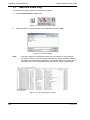
Test the operation of all connected cameras by selecting each camera in turn from the drop
down list on the user interface.
Figure 30: Camera List
24
Doc 13972_03
ADPRO FastTrace-R by Xtralis
Installation and User Manual
2.12 Notes and Troubleshooting Tips
•
•
Ensure that details entered at VideoCentral AND the FastTrace-R are IDENTICAL.
Ensure the TCP/IP address and subnet mask are correct.
2.12.1 Setting the Date and Time
The FastTrace-R uses a stable internal clock that is based on UTC (Coordinated Universal
Time). Date and time settings of the unit operate in a way that is similar to a PC and a 'Time
Zone' value is provided in the Date / Time Settings option of the Connection menu / Installer
Menu option.
To ensure correct operation, the Time Zone value should be configured prior to any date or time
changes being made.
2.12.2 Front Panel LED
When power is first applied to the FastTrace-R unit, the red LED on the front of the unit will be on.
After approximately 60 seconds, the red LED should start switching on, then off, every two
seconds. This signifies that the unit has completed its internal checks and is now checking the
integrity of the database. Once the unit successfully completes the integrity check, the red LED
will switch off, and remain off.
If at any time during operation, the red LED switches on and stays on, this signifies a fault with
the unit and technical support is required.
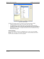
2.13 FastTrace-R Connection Details Lost
If for any reason, the operational Site ID, password or network address for a FastTrace-R is lost,
use the following procedure to override the communication settings and restore this information.
1.
Set the FastTrace-R's DIP Switch 7 (on the rear panel) to the 'ON' position.
2.
Power cycle the unit. This will override to the following settings:
Site ID: FT-R
Password: FT2222
Network Address: 192.168.1.1
Subnet Mask: 255.255.255.0
3.
Connect a crossover network cable or the null modem (serial) cable between the unit and a
PC running VideoCentral.
4.
There should be a FastTrace-R Default Site in Database / Administration / Site Details
with details that match the Site Details as described in point 2 above.
5.
Modify the VideoCentral settings (Database / Administration / Site Details) for the
connection type as follows:
(NETWORK connection) - Set 'Connection Type' = Network and 'IP Address' =
192.168.1.1
OR
-
(SERIAL connection) Set 'Connection Type' = PSTN and 'Phone' = 0
6.
Connect to Site using the default Password (FT2222).
7.
Go to the Connection menu and select the Installer Menu option to display the FastTraceR's User Settings menu.
8.
Change Site Details to the new Site ID, Password and Network Address values.
Doc 13972_03
25
Installation and User Manual
9.
ADPRO FastTrace-R by Xtralis
Save all changes when exiting the User Settings menu.
10. Reset Switch 7 to the OFF position and power cycle the unit.
The FastTrace-R will now operate with the new Site ID, Password and Network Address.
2.14 Firewall Configuration
If the FastTrace-R unit is connected via a firewall, the following table describes the destination
port allocation for the VideoCentral PC and FastTrace-R unit. Source ports are randomly chosen.
The control of connections should be done using IP addresses and destination ports.
Table 1: Firewall Ports
26
Destination Ports on VideoCentral
Destination Ports on FastTrace-R
UDP 15000-15200
UDP 15000-15005
TCP 15001-15007
TCP Any port
Doc 13972_03
ADPRO FastTrace-R by Xtralis
3
Installation and User Manual
FastTrace-R Connectors
All external connections to the FastTrace-R chassis are made via the rear panel, refer to the
following figure:
Figure 31: FastTrace-R Connections
Doc 13972_03
27
Installation and User Manual
3.1
ADPRO FastTrace-R by Xtralis
Power Connection
The FastTrace-R is designed for 100-240 VAC 50-60Hz operation. Ensure mains supplies are
stable and are not subject to frequency changes, voltage spikes etc. The use of mains
suppression units or even UPS (Uninterrupted Power Supply) systems is recommended to
ensure stable voltages.
Maximum input current is 5 amps during power up and 1 amp during normal operation. Typical
unit power consumption when fully optioned is 100 W.
3.2
Connecting Communication Devices
FastTrace-R provides a number of interfaces for connecting communications devices to allow
remote access to the system for setup and review of stored information. These interfaces are
available via the COMMS 1, COMMS 2 and NETWORK connectors on the rear panel.
In general, there are three primary types of communication links available; dial-up, dedicated or
network. Both dial-up and dedicated links can be either analogue (PSTN) or digital (ISDN),
depending of the type of connections available at the site.
There are a variety of different networks that are available, and with the appropriate interface the
FastTrace-R can work over the majority of them.
3.2.1 COMMS 1
COMMS 1 is a serial communication port and is used to connect to modems and terminal
adaptors to support PSTN and ISDN links at data rates up to 230 kps. The 25-pin D connector
pins are wired as shown below.
Figure 32: Comm1 Pin Numbers
Table 2: Comm Port 1 Connection
V.24 Name
28
Pin
Direction
V.24 Description
SGND
1
-
Shield
TXD
2
O
Transmit data
RXD
3
I
Receive data
RTS
4
O
Request to send
CTS
5
I
Clear to send
DSR
6
I
Data Set Ready
GND
7
-
Signal ground
DCD
8
I
Carrier detect
9
I
Doc 13972_03
ADPRO FastTrace-R by Xtralis
V.24 Name
Installation and User Manual
Pin
Direction
10
I
11
O
12
I
13
I
14
O
15
I
16
I
17
I
18
I
19
O
DTR
20
O
Data terminal ready
RL
21
O
Remote loopback
RI
22
I
Ring Indicator
23
I
24
O
25
|
SCT
RXC
TXC
V.24 Description
DCE transmit clock
DCE receive clock
DTE Transmit Clock
3.2.2 COMMS 2
COMMS 2 is used to connect to modems and terminal adaptors to support PSTN and ISDN links
at data rates up to 230 kbps. COMMS 2 can also be used to access the FastTrace-R setup menu
and to upgrade the software when connected to a PC or laptop computer via a null-modem cable
link. The 9-pin D connector pins are shown below.
Table 3: Comm Port 2 Connection
Doc 13972_03
Name
Pin
Direction
Description
DCD
1
|
Carrier Detect
RXD
2
|
Receive Data
TXD
3
O
Transmit Data
DTR
4
O
Data Terminal Ready
GND
5
-
Ground
DSR
6
|
Data Set Ready
RTS
7
O
Request to Send
CTS
8
|
Clear to Send
RI
9
|
Ring Indicator
29
Installation and User Manual
ADPRO FastTrace-R by Xtralis
3.2.3 Connecting to a Modem or TA
Communication devices with a V.24 port are connected to the FastTrace-R using the modem
cable supplied with the modem or terminal adaptor. Either Comms 1 or Comms 2 may be used
and the FastTrace-R can be set up with two communications devices, allowing simultaneous
connections and / or a back-up communications path.
Figure 33: Modem Connection
3.2.4 Network (Ethernet) Connection
FastTrace-R has a built in Ethernet connection port to allow communications via a conventional
'computer' network.
•
NETWORK - (RJ-45 - Female) - Ethernet 10/100baseT
Caution:
To ensure correct network connectivity, please ensure FastTrace-R is connected to
the network before being powered on. This enables the FastTrace-R unit to detect
the correct network speed (10BaseT or 100BaseT).
The physical connection is a half-duplex, 10/100Base-T (100Mb) port, although the maximum
throughput of the FastTrace-R is around 5Mb/sec.
FastTrace-R is designed for use via a Cat5 cable infrastructure. The Cat5 standards define
cabling specifications and physical presentations. In short, Cat5 defines the use of 4 pairs (8
wires) presented on an RJ45 connection. Cat 5 cable must be used for operation on a 100baseT
wiring system. The physical connections are:
Table 4: Ethernet Connection
Pin No.
30
Function/Signal
1
Transmit +ve
2
Transmit -ve
3
Receiver +ve
4
Not Used
5
Not Used
6
Receive -ve
7
Not Used
8
Not Used
Doc 13972_03
ADPRO FastTrace-R by Xtralis
Note:
Installation and User Manual
ALWAYS consult with the IT or Network Manager for the network BEFORE
physically connecting FastTrace-R to the network.
A network address is required for correct operation over a network. Both the FastTrace-R and
the PC running the VideoCentral software must have a unique TCP/IP address (referred to as
the IP address). A number of IP parameters may need to be entered to correctly identify a
FastTrace-R on a network.
Refer to Section 4 - Ethernet Properties for details to configure the Ethernet Connection.
3.3
Audio
Audio functionality is provided via two connectors on the FastTrace-R. Audio options are only
available if the system has a sound card enabled. Audio to/from a remote site using VideoCentral
is half-duplex, meaning that audio is only allowable in one direction at a time.
3.3.1 Audio Switch Port
The Audio Switch port provides a number of functions on the FastTrace-R, these are:
•
•
•
•
An audio output and an audio input connection
A general relay
Serial outputs
Access Secure input
'AUDIO SWITCHER'
15-pin D Male Connector
Pin 1
Pin 8
Pin 15
P73 audio pinouts d-conn.cdr
Figure 34: Audio D-Connector Pinouts
Doc 13972_03
31
Installation and User Manual
ADPRO FastTrace-R by Xtralis
Table 5: Audio Switcher Connections
Pin Function
Serial Link for Channel
Number selection
Signal
Pin
Specifications
Serial Clock
14
Serial Data
7
Open drain output
32 V maximum
100 mA maximum
On impedance <15 ohm
Serial Strobe
Audio Signals
15
not used
8
Audio Out (+)
1
Output impedance >600 ohm
Nominal output level = 315 mVrms
Audio In (+)
2
Input impedance >6K ohm
Nominal level = 10 mVrms to 400 mVrms
Audio Common
9
Audio Signal common
Spare
not used
13
Access/Secure
Acc/Sec Input
5
Spare
not used
6
General Alarm Relay
Common
4
Contact Rating 1 A at 32 VDC
Ground
N/O
12
N/C
11
Ground
10
N/C
3
3.3.2 Audio Screw Terminal Connector
The audio screw terminals may be used for connection of certain audio devices, such as
microphones and low power speakers. Connections and ratings of the connector block are:
'AUDIO'
9-pin DECA Connector
3
4
7
8
9
MIC -
GND
GND
GND
6
MIC +
IN
OUT
5
SPKR -
2
SPKR +
1
P73 audio pinouts conn.cdr
Figure 35: Audio Connector Pinouts
32
Doc 13972_03
ADPRO FastTrace-R by Xtralis
Installation and User Manual
Table 6: Audio Screw Terminal Connector
Pin Function
Signal
Pin
Line Level Audio
Output
1
Unbalanced, impedance 600 ohm
Nominal voltage level = 315 mVrms
Ground
2
0V
Input
3
Unbalanced, impedance >6 K ohm
Nominal level = 10 mVrms to 400 mVrms
Ground
4
Speaker (+)
Speaker (-)
5
6
Ground
7
Microphone (+)
Microphone (-)
8
9
Local Speaker
Local Microphone
Specifications
Balanced, impedance = 8 ohm
Nominal output power = 1 W
Total harmonic distortion < 5%
Differential impedance > 3 K ohm
Single ended impedance > 6 K ohm
Nominal signal level is
100 uV rms to 10 mV rms
3.3.3 Audio Configuration
The audio output is normally connected to the input of an amplifier capable of driving a speaker.
With a suitable amplifier, multiple speakers may be driven to give a global announcement. The
output level is approximately equal to the input level provided at the receiver.
1
Audio Output
1
Ground
2
2
3
4
5
6
7
8
9
Audio Connector Port
Amplifier capable of
driving a number
of horns
Loud speakers
Figure 36: Audio Configuration with Amplifier
The audio input is normally connected to a microphone with a suitable pre-amplifier stage that is
capable of providing 1 V peak to peak audio.
Doc 13972_03
33
Installation and User Manual
Audio Input
3
Ground
2
ADPRO FastTrace-R by Xtralis
Microphone
Pre-amplifier
1
2
3
4
5
6
7
8
9
Audio Connector Port
Figure 37: Microphone Connection
By using both the audio input and output, intercom systems and handsets can also be connected
to the FastTrace-R. When used in conjunction with the alarm inputs this allows the FastTrace-R
to be used for help points and door/gate entry systems.
To the FastTrace's
alarm inputs
1
Audio Input
3
Audio Output
1
Ground
2
2
3
4
5
6
7
8
Amplifier dedicated
for use with the
selected intercom
9
Intercom point
with speaker,
microphone and
attention button
Audio Connector Port
Figure 38: FastTrace-R with Intercom
The FastTrace-R can send audio simultaneously with the video on PSTN, ISDN lines and over
Networks. This enables the central station to 'listen and talk' to activities occurring on the
monitored site.
3.3.4 Zoned Audio
The FastTrace-R has one audio input and output. If zoned audio is required, that is the ability to
talk out of individual speakers rather than making a global announcement, or if it is required to
listen to multiple microphones, a VM22A can be used. This also means a mixture of intercoms
and loud speakers can be used.
The VM22A audio switcher has ten audio inputs and outputs (one for each video input) and will
route the appropriate audio input and output to the FastTrace-R, depending upon which camera
the monitoring station is currently viewing.
Additional VM22As can be connected to the first VM22A to expand the audio channels to 20 (the
same number as number of cameras on a FastTrace-R 2020).
34
Doc 13972_03
ADPRO FastTrace-R by Xtralis
Installation and User Manual
Figure 39: Zoned Audio Configuration
3.4
Video Input Connections
Depending on the model, up to 20 video sources can be connected via the female BNC sockets.
The sources should generate a 1.0-volt peak to peak composite colour or black and white video
signal when terminated with a 75-ohm load. A combination of colour and black and white
cameras can be used.
To ensure high picture quality, each video input must be terminated either at the chassis itself or
by other external equipment. The Camera Terminated option in the Connected Equipment /
Cameras screen (via the Connection menu / Installer Menu option) allows individual channels
to be terminated with 75-ohm or left un-terminated, for example, when the video signal is looped
out to other equipment such as a video monitor or video matrix switcher. The external equipment
must provide the channel termination. The default menu option is Camera Terminated.
Caution:
Doc 13972_03
Video terminations are OFF when power is removed.
The video terminators on the FastTrace-R will disconnect when power to the unit is
removed. If the video inputs are also connected to other equipment, the FastTraceR should NOT be used to provide a 75-ohm termination point.
35
Installation and User Manual
Caution:
ADPRO FastTrace-R by Xtralis
Installations in Lightning Prone Areas
In lightning prone areas, in-line coaxial lightning arresters should be used on the
video cables. The arresters should be installed at the cable entry of the building that
houses the FastTrace-R. Cameras should also have suitable lightning protection
rods installed as close to them as possible. The use of fibre optics to provide
electrical isolation on the video signals is strongly recommended in high-risk areas.
Figure 40: Video Configuration
3.4.1 Video Input Requirements
To ensure high quality images, the FastTrace-R must synchronise correctly to the incoming video
signal for the selected video standard. For synchronisation to occur the following conditions must
be met:
•
•
•
the synchronisation pulse amplitude at each video input must be within the range of
0.2 volts to 0.4 volts,
the peak video amplitude with reference to the black level (ie. not including the
synchronisation pulses) at each video input must be within the range of 0.5 volt to 1.0 volt,
and
for colour cameras, the minimum colour burst level at each video input must be at least
100 mV.
If the video level is low, cable compensators or video line drivers should be installed at the video
source. They should be adjusted to boost the video signal to within the voltage limits given
above.
36
Doc 13972_03
ADPRO FastTrace-R by Xtralis
Installation and User Manual
Maximum Camera Input Cable Length
The maximum cable length that can be used from a camera before cable compensators are
required is dictated by the desired quality of the video picture. Generally, the shorter the cable
between the camera and the FastTrace-R the better the video picture quality.
Use the following information as a guide for RG59 type coaxial cable (75 ohm nominal
impedance):
•
In a monochrome system, depending on the resolution required, the cable length should be
restricted to 500 metres (1600 feet) before cable compensators are installed.
Signal degradation due to the coaxial cables characteristics has a far greater effect on colour
video. In a colour system, the coaxial cable length should be limited to 250 metres (800 feet)
before cable compensators are installed. Again the length is dependent on the required picture
quality.
3.5
Video Output
The video output of the FastTrace-R is normally connected to a colour or monochrome monitor
capable of receiving composite video signal to the required TV standard (PAL/CCIR or NTSC/
RS170). The composite video output is designed to drive a 75ohm load.
Figure 41: Video Output Configuration
The video output cannot be controlled under normal day to day operation and will provide a
sequence of images as defined in Monitor Settings. This may be used in environments such as
entrances to buildings etc, where CCTV is being used, to act as a deterrent.
3.6
Configuration Switches
Some of the FastTrace-R settings and functions are set by the configuration switches on the rear
panel.
Settings shown in bold are the factory default positions.
Doc 13972_03
37
Installation and User Manual
ADPRO FastTrace-R by Xtralis
Table 7: DIP Switch Configuration
Switch
1
2
Function
On
Off
Factory Set
On
Factory Set
Off
3
On
Off
4
5
6
7
Factory Set
On
Off
Factory Set
On
RS422 Configuration for PTZ port
Off
RS485 Configuration for PTZ port
On
Impounded
Off
Normal Operating Position
On
Default override setting for direct connection
Note: Refer to FastTrace-R Connection Details Lost for
an explanation of this switch functionality.
Off
Normal Operating Position
On
PTZ RS485 Termination On
Off
PTZ RS485 Termination Off
On
GP Serial 2 is enabled for EPOS/ATM interfacing
Off
Factory Set
On
NTSC Video Standard
Off
PAL Video Standard
11
N/A
Leave both switches 11 and 12 in the ON position
12
N/A
8
9
10
After changing any DIP switches the FastTrace-R must be repowered for the changes to take
effect.
The impound switch (DIP switch 6) will stop the system recording or deleting any data on the
disks. This can be used where a complete unit is required for evidential purposes (refer to
Section 6 - FastTrace-R Impounding).
38
Doc 13972_03
ADPRO FastTrace-R by Xtralis
3.7
Installation and User Manual
Alarm Inputs
Unlike other equipment, which typically has statically assigned alarm input to video relationships
(i.e. alarm input 1 always related to video channel 1, alarm input 2 always related to video
channel 2, etc), FastTrace-R can be programmed so that any one or group of alarm inputs can
trigger any one or group of cameras. This allows much more flexibility within system designs and
configurations.
The FastTrace-R Model 5020 has thirty external alarm inputs, all with selectable tamper
detection configurations (Model 5010 has twenty). The camera setup options can be
programmed to trigger an alarm on detection of either a closed contact or an open contact
condition on an alarm input. Alarm inputs are normally connected to alarm sensors such as door
switches, passive infrared detectors, microwave detectors, vibration sensors, electric field
detectors, etc.
In addition to this, alarm inputs can also be programmed as being one of six states to allow for
tamper detection on circuits. Alarm types can be:
•
•
•
•
•
•
Normally Open - No End Of Line (NEOL) Resistor
Normally Closed - NEOL
Normally Open - Single End Of Line (SEOL) Resistor
Normally Closed - SEOL
Normally Open - Dual End Of Line (DEOL) Resistor
Normally Closed - Dual End Of Line Resistor
Alarm inputs to the FastTrace-R are presented on screw terminals on the rear of the unit and
each circuit can be individually assigned as one of the above six types (i.e. a combination may
be used, you do not have to program them all the same way).
Alarm inputs are relative to ground (chassis) of the FastTrace-R.
Doc 13972_03
39
Installation and User Manual
ADPRO FastTrace-R by Xtralis
Figure 42: Alarm Input Configuration
3.7.1 Driving the Alarm Inputs
For an alarm input to be recognised, the input device must hold a changed state for a period of
100 ms.
•
•
For a valid closed contact, the total resistance, including wiring resistance, must be below
150 ohms.
For an open contact to be valid the resistance presented at the alarm input must be above
2,500 ohms.
The alarm inputs and numbering for all channels is shown below. Note that the alarm input
ground connections are not isolated from the chassis ground.
40
Doc 13972_03
ADPRO FastTrace-R by Xtralis
Installation and User Manual
Figure 43: Alarm Connector Pinouts
Wire connections from the alarm switches are made by using the screw terminal contact strips
supplied with the FastTrace-R. For ease of installation, the screw terminal blocks slide over the
connector pins when the wiring is complete.
Caution:
DO NOT attempt to solder directly onto the connector pins, as this may cause heat
damage to the connector housing or to the interface PCB.
The setup options for alarm inputs are described with reference to the ‘rest’ or non-alarm position
of a set of switch contacts:
•
•
•
•
•
•
Doc 13972_03
Normally Open - needs a closing alarm contact to activate an alarm
Normally Closed - needs an opening alarm contact to activate an alarm
SEOL Normally Open - Single End of Line termination with N/O contacts
SEOL Normally Closed - Single End of Line termination with N/C contacts
DEOL Normally Open - Dual End of Line termination with N/O contacts
DEOL Normally Closed - Dual End of Line termination with N/C contacts
41
Installation and User Manual
ADPRO FastTrace-R by Xtralis
Figure 44: External Sensor Wiring Circuits
Please refer to Specifications for voltage requirements and considerations.
3.8
Control Outputs
FastTrace-R has 10 or 20 Control Outputs that can be controlled by a remote operator using
VideoCentral. The devices can be used to control operation of lights, gates / doors and control
equipment.
Note:
Each Control Output can be set to be active (switch on) when an alarm event is
active on the corresponding channel or to respond to remote control via
VideoCentral.
The devices should not be used to directly connect to third party equipment. They are primarily
designed to drive relay contacts, which in turn control the third party equipment.
42
Doc 13972_03
ADPRO FastTrace-R by Xtralis
Installation and User Manual
3.8.1 Connecting to the Control Outputs
Control Outputs are available via screw connection strips on the rear panel.
Figure 45: Pinouts for Control Output Connectors
Caution:
Exceeding the Control Output’s maximum voltage or current rating
(12 Vdc, 100 mA) will damage the FastTrace-R and invalidate the product warranty.
For high power/voltage equipment, suitable interface circuitry must be used
between the Control Outputs and the equipment.
A typical output circuit for an external relay is shown below:
Figure 46: External Relay - Typical Output Circuit
3.9
PTZ Connection
Telemetry stations are used for the control of cameras with Pan/Tilt/Zoom (PTZ) hardware. They
are connected to the FastTrace-R and can be controlled by commands issued via the PTZ port
connector.
FastTrace-R supports a number of PTZ telemetry station models provided all of the PTZ units are
the same model. Communications with the telemetry stations utilises RS485 ‘multi-drop’
signalling via the ‘PTZ’ port on the rear of the chassis.
FastTrace-R supports ‘Down the Coax’ telemetry. A ‘Down the Coax’ telemetry module must be
installed in the FastTrace-R if this functionality is required. Please contact your service centre if
this option is required.
Doc 13972_03
43
Installation and User Manual
ADPRO FastTrace-R by Xtralis
A single 9-way D connector is provided on the unit to support RS422 and RS485 connectivity to
PTZ camera stations. The connectivity is shown below. To change between RS422 and RS485,
use DIP switch 5 on the rear of the unit. To provide termination of the RS485 line use DIP switch
8 on the rear of the unit.
Figure 47: Pin Numbering of the PTZ Port
Table 8: PTZ Port Connections
Name
Pin
Description
TXD+
2
RS422(+) / RS485 (+)
TXD-
3
RS422 (-) / RS485 (-)
GND
5
Signal Ground
RXD+
6
RS422 (+)
RXD-
7
RS422 (-)
Figure 48: Typical RS485 Connection to Multiple Telemetry Stations
44
Doc 13972_03
ADPRO FastTrace-R by Xtralis
Installation and User Manual
Figure 49: Typical PTZ Configuration
3.9.1 PTZ Port Setup
The following points are applicable to the PTZ port.
•
•
•
Telemetry stations are connected via a 9-pin D connector, marked ‘PTZ’
RS485 control links allow cable lengths of up to 1000 metres
Up to 20 (identical) telemetry stations can be connected to one FastTrace-R
Use the following guidelines when connecting and setting up a telemetry station.
•
•
•
•
Doc 13972_03
The same brand and model of telemetry station must be used at a site if multiple units are to
be used.
Set the address of the telemetry station to match the camera input to which the PTZ camera
is connected.
Use shielded twisted pair cable for connection to the telemetry stations.
Connect the Transmit positive (TXD+ pin#2), Transmit negative (TXD- pin#3) and Ground
terminal (pin#5) of the FastTrace-R PTZ connector to the respective positive, negative and
ground terminals of the telemetry station as shown below.
45
Installation and User Manual
ADPRO FastTrace-R by Xtralis
PTZ Camera Station
RS422/485 Port
Balanced
Transmit/
Receive
FastTrace
PTZ Port
(+)
2 (+)
(-)
3 (-)
Ground
5
Balanced
Transmit/
Receive
Ground
Shield
RS485 ft connection.cdr
Figure 50: RS485 PTZ Port Connections to a Telemetry Station
•
•
Make sure the last telemetry station connected to the link is terminated by a 120 ohm
resistor.
With reference to the telemetry station manual:
connect the pan/tilt head and the zoom lens, focus control and iris control (if
applicable),
set the lens voltage, high speed PTZ settings, A/D converter for preset systems,
homing preset after the last operation plus any other settings in the telemetry station,
and
make sure the telemetry station data speed is set to the ADPRO recommended or
default baud rate.
Telemetry station manufacturers provide a variety of models and features. FastTrace-R provides
PTZ control ability for a number of popular models and where possible, supports the features
provided by the manufacturer. Due to the number of models available on the commercial market,
details of connection and use for individual models have been provided on the website.
For information regarding connection and features of specific telemetry station, please
refer to the technical documents section on the website at:
http://www.xtralis.com/adpro
or contact your nearest sales office for a copy.
3.10 General Purpose Serial Ports
Two general purpose serial ports are provided on the unit to support RS232 communication to
third party equipment, for example transaction devices such as ATM / EPOS machines. The
connectivity is shown below.
If using the GP Serial Port for ATM /EPOS, please ensure that configuration switch 9 is in
the correct position prior to boot-up.
Figure 51: Pin Numbering of the Serial Port
46
Doc 13972_03
ADPRO FastTrace-R by Xtralis
Installation and User Manual
Table 9: General Purpose Serial Port Connections
PIN
Signal
Description
1
DCD
Carrier Detect
2
RXD
Receive Data
3
TXD
Transmit Data
4
DTR
Data Terminal Ready
5
GND
Ground
6
DSR
Data Set Ready
7
RTS
Request to send
8
CTS
Clear to send
9
RI
Ring Indicator
Figure 52: Typical Configuration with ATM/EPOS
3.11 Data Connection
A single 9-way D connector is provided on the unit for data connection, such as Transparent
RS232. The transparent data capability provides the ability for the system to transfer data from a
device connected to a serial port on the VideoCentral PC to the data port on the FastTrace-R and
vice versa. The data connection supports baud rates of 1200, 2400, 4800, 9600, 19200, 38400
and 57600.
Doc 13972_03
47
Installation and User Manual
ADPRO FastTrace-R by Xtralis
Figure 53: Pin Numbering of the Data Port
Table 10: Data Port Connections
PIN
Signal
Description
1
DCD
Carrier Detect
2
RXD
Receive Data
3
TXD
Transmit Data
4
DTR
Data Terminal Ready
5
GND
Signal Ground
6
DSR
Data Set Ready
7
RTS
Request to send
8
CTS
Clear to send
9
+V
Signal High
3.12 Connecting to the General I/O
General Inputs/Outputs are available via screw connection strips on the rear panel.
15-pin Screw Terminal Connector
4
5
6
7
ALM COM
ALM NO
15
FLT COM
10 11 12 13 14
FLT NO
GND
GND
GND
9
PTT
CLK
A/S
EE
8
ALM NC
3
FLT NC
2
GND
1
MOD SEL
Pins 1-15
P73 general io pinouts.cdr
Figure 54: Pinouts for General I/O Connector
3.12.1 Export Evidence - Pin 1
Currently not used.
3.12.2 Access/Secure Input - Pin 3
Not used in FastTrace-R operation.
48
Doc 13972_03
ADPRO FastTrace-R by Xtralis
Installation and User Manual
3.12.3 Clock Synchronise - Pin 5
Currently unused.
3.12.4 Push to Talk - Pin 7
Currently unused.
3.12.5 Mode Select Input - Pin 9
The way a FastTrace-R operates its recording and alarm event recording features can be
changed by using up to four different operating ‘modes’. The parameters that define a particular
mode of operation, such as recording rate and alarm recording responses, are configured by
using the FastTrace-R Installer Menu.
From the FastTrace-R Installer Menu, any two (of the four) operating modes can be assigned to
activate depending on the open/closed state of the Mode Select input pin.
When the Mode Select pin is ‘open’ (or ‘high’), the FastTrace-R operates by using the mode
parameters assigned to that pin state. Placing a ‘closed contact’ on the pin switches the unit into
an alternate mode.
3.12.6 Fault Relay
FastTrace-R has a fault relay, which is a double pole type, i.e. complementary Normally Open/
Normally Closed poles, on pins 13, 14 and 15 of the General Inputs/Outputs connector. The Fault
relay activates while the FastTrace-R is in a fault state. The contacts will remain in the
changeover condition until reset.
The operation is as follows:
•
•
•
•
When the unit is powered off, the relay is Normally Closed.
When the unit powers up and is booting, i.e. the red light is on or flashing, the fault relay is
Normally Closed.
When the unit is operating normally, the fault relay will be Normally Open.
In the case of an over-temperature situation, the fault relay will be Normally Closed until the
temperature returns to normal.
Ratings:
Switching Voltage
Switching Current
Isolation
= 30 VDC maximum
= 1 Amp maximum
= 750 V maximum
3.12.7 General Alarm Relay Output
Pins 10, 11 and 12 contain a Form C single pole changeover contact set. If configured to do so,
the General Alarm relay activates while the FastTrace-R has an alarm recording event active.
The contacts will remain in the changeover condition until all alarms are reset.
Ratings:
Switching Voltage
Switching Current
Isolation
= 30 VDC maximum
= 1 Amp maximum
= 750 V maximum
The relay may also be configured to activate whenever the unit is connected via a network or
data link to the Remote Viewing Software (e.g. VideoCentral). This feature may be used (for
instance) to notify a third-party alarm system when FastTrace-R activity is taking place.
Doc 13972_03
49
Installation and User Manual
ADPRO FastTrace-R by Xtralis
3.13 Powering Up the FastTrace-R
The FastTrace-R is supplied with a universal input power supply which operates from 100-240 V
AC, 50-60 Hz. There are no switches to change based upon your particular mains power voltage
or frequency.
When power is applied to the FastTrace-R the green LED located on the front panel of the unit
will illuminate.
If the green LED fails to illuminate check that there is power available from the socket into which
the FastTrace-R is connected.
The FastTrace-R will then automatically perform a series of self-test routines which check the
microprocessor circuits. When power is first applied to the FastTrace-R unit, the red LED on the
front of the unit will be on. After approximately 60 seconds, the red LED should start switching
on, then off, every two seconds. This signifies that the unit has completed its internal checks and
is now checking the integrity of the HDDs. Once the unit successfully completes the integrity
check, the red LED will switch off, and remain off.
If at any time during operation, the red LED switches on and stays on, this signifies a fault with
the unit and technical support is required.
If the red LED does not switch off and remain off, do the following:
1.
2.
3.
Unplug all of the connectors except the power and re-power the unit.
If the red LED extinguishes, plug each connector back in and check that the red LED
remains off.
If the red LED does not extinguish after 10 minutes, please contact ADPRO technical
support.
If the red LED continues to flash for an extended period, this signifies that corruption has been
found with the database and the unit is attempting to correct the fault.
50
Doc 13972_03
ADPRO FastTrace-R by Xtralis
4
Installation and User Manual
Programming FastTrace-R
4.1
Programming Checklist
The following checklist provides an overview of the main tasks required to program a FastTraceR and the sequence in which they should be performed:
•
•
•
Set the unique Site ID and Password for the FastTrace-R and ensure that matching ones
are entered in VideoCentral (refer to Site Details).
Set the time zone on the FastTrace-R to the time zone of the site location (refer to Date/
Time Settings).
Ensure all connected cameras are programmed (refer to Cameras and Camera Behaviour).
4.2
Setting the Operational Parameters
The FastTrace-R is factory configured with 'typical' operating values, but to use the FastTrace-R
in an operational environment, its configuration must be modified to use the site names, phone
numbers or network addresses that match the real network.
Once the FastTrace-R settings have been configured, the VideoCentral settings must be
updated to match.
4.2.1 Setting the Network Connection
The ADPRO VideoCentral software will require some basic information in order to connect to any
FastTrace-R site via a network connection. The minimum information that must be configured in
each FastTrace-R is shown below.
To enter the information, go to Database / Administration / Configure Sites, select the Edit
option, then highlight Network in the Communications section.
•
•
•
Site ID: 9 characters (max) - your name for the FastTrace-R unit
Password: 8 characters (max)
IP Address: The TCP/IP network address assigned to each FastTrace-R (this address is
normally assigned by the network manager)
Your IT manager should be able to provide the IP address settings. Once the basic connection
details have been configured and saved, the FastTrace-R is ready to connect via the operational
network.
Note:
The default FastTrace-R IP Address is 192.168.1.1.
4.2.2 Setting the Telephone Connection
The basic information needed to use a telephone (dial-up) connection is entered via the
Database / Administration / Configure Sites menu. Select the Edit option, then highlight
PSTN or ISDN in the Communications section:
•
•
•
•
Doc 13972_03
Site ID: 9 characters (max) - your name for the FastTrace-R unit
Password: 8 characters (max)
Hunt Group: Select from the list (Note: Different modem types must be installed via the
Windows Control Panel)
Phone Number: Enter the phone number of the modem connected to the FastTrace-R.
51
Installation and User Manual
4.3
Note:
ADPRO FastTrace-R by Xtralis
Entering the FastTrace-R Setup Screen
Always use extreme caution when remotely programming FastTrace-R units.
Changing connection parameters or passwords may result in the VideoCentral
system not being able to regain access, resulting in the need for engineering
attendance at the site to reprogram the system.
Remote programming of FastTrace-R systems is carried out via a screen as shown below. To
start the programming operation, click on the Installer Menu button behind the Site Actions
button in the main VideoCentral User Interface GUI:
Figure 55: Installer Menu Icon
Note:
Only operators logged on to the system either as Administrators or Installers have
access to this icon. Users defined as Operators do not have access to this function.
If this icon does not appear or appears greyed out, log out the current operator and
log-on a new operator with the correct access rights.
The current settings within the FastTrace-R will be downloaded to the VideoCentral system and
the following screen will appear:
52
Doc 13972_03
ADPRO FastTrace-R by Xtralis
Installation and User Manual
Figure 56: FastTrace-R User Settings
Note:
Some options for a category can be affected by the status of other setting(s) and
may be unavailable (shown ‘ghosted’).
The programming GUI is a separate program to VideoCentral and there are numerous different
versions (although outwardly all look the same). The precise version used is dependent upon the
software installed on the FastTrace-R system being programmed. The programming software is
held on the remote FastTrace-R system and downloaded to the VideoCentral PC for use. For this
reason the programming screen may sometimes takes a few minutes to appear on the screen
(depending upon the speed of the connection to the FastTrace-R system). VideoCentral only
needs to download any given version of the programming software once, after this the software
is stored on the PC for use at a later time, speeding up the programming operation. Once the
settings (and set-up program if necessary) have been downloaded the programming software
will start automatically.
Selecting the Save to FastTrace-R button at any time will cause all settings currently within the
software to be sent to the FastTrace-R system (a confirmation box will be presented to verify the
required action). Before sending the new programming to the FastTrace-R, the software will
perform a check to make sure all settings are valid and any anomalies will be advised.
Once all settings are valid, they will be downloaded to the FastTrace-R system and the system
will be disconnected to allow the settings to take effect.
Selecting the Discard all changes button any time will close the Setup without sending any
settings to the remote FastTrace-R system (a confirmation box will be presented to verify the
required action).
Doc 13972_03
53
Installation and User Manual
ADPRO FastTrace-R by Xtralis
4.3.1 Saving a Configuration to File
Selecting the Save to File … button displays the Save As dialog box.
•
•
•
Files are saved in a ‘FT-R User Settings (*.fus)’ file format.
Characters such as ':', '*' and '?' in the filename are invalid and will not be accepted.
If the file already exists, the user shall be asked whether or not they wish to overwrite the
existing file.
If an error in saving occurs, such as insufficient storage space, the user will be informed of the
error by a dialog box.
4.3.2 Loading a Configuration from File
Selecting the Load from File … button displays the Load Settings dialog box.
•
•
•
The ‘Files of type’ drop down list is displayed as default ‘User Settings (*.fus)’.
Select Open to open the file.
The user is prompted whether or not to use the Ethernet IP settings from the file to be
loaded or to retain the current ones. The following dialog is displayed:
Figure 57: TCP IP Settings
Note:
Users are warned to take note of the IP address in the FastTrace-R unit before
saving settings to ensure the unit can be contacted once setup is complete and the
site is disconnected.
If the selected settings file is incompatible, then the following dialog is displayed:
Figure 58: Incompatible User Settings File
The reasons for receiving the above dialog can include:
•
•
Attempting to use a settings file that is newer than the unit’s current software version allows.
Attempting to load settings files using a version of the setup GUI that is newer than the
unit’s current version of setup GUI.
To rectify this, the user must either use an older setup file, or upgrade the FastTrace-R.
If the saved settings file is corrupted or unsupported, the Save to FT-R button is disabled to
prevent that file being used by the FastTrace-R. If a valid settings file is selected the Save to FTR button is re-enabled.
54
Doc 13972_03
ADPRO FastTrace-R by Xtralis
Installation and User Manual
4.3.3 Site Details
Figure 59: Site Details Menu
Site ID
Each ADPRO FastTrace-R must have a unique site ID. The maximum site ID alpha-numeric
length is 9 characters. Note that the ‘local’ site ID entered here must match a site ID entry in the
VideoCentral Site List (Database / Administration / Configure Sites).
The default site ID is FastTrace-R.
Passwords
VideoCentral may be installed as a CMS system, which will receive alarms (VC Gold or VC Lite
with dongle), or as an Observer, which will not receive alarms (VC Lite without dongle). When
configuring sites in VideoCentral (Database / Administration / Configure Sites / Edit) either
the Observer password or CMS password must be entered, depending on the type of
VideoCentral installation.
The default CMS password is FT2222.
The default Observer password is FT1111.
Doc 13972_03
55
Installation and User Manual
ADPRO FastTrace-R by Xtralis
4.3.4 Date/Time Settings
To enable accurate event tracking, the FastTrace-R can be set to accommodate local or regional
daylight saving time shifts when they affect the location where the FastTrace-R is installed.
Figure 60: Date/Time Settings Menu
Time Zone
Database records within the FastTrace-R are timestamped using Coordinated Universal Time
(abbreviated as UTC). The Time Zone field is used to define the number of hours and minutes
that the actual site location is ahead (or behind) the UTC reference of 0 degrees of longitude
(originally known as Greenwich Mean Time).
Daylight Saving
In regions where daylight saving is implemented over the summer months, users can enter the
local start and finish dates to ensure the FastTrace-R clock is automatically corrected. The
Daylight Savings Enable check box is used to start this feature and allow entry of the start and
finish dates.
FastTrace-R implements daylight saving start and finish at 2 am local time (02H00) and will
advance or set back the time by 1 hour accordingly.
Caution:
When the FastTrace-R unit is shipped from the factory, Universal Time is
programmed in the unit and is used as the ‘current’ time. To match the ‘current’ time
to the local time at your location, change the time zone setting to the correct zone.
Changes to the value of the ‘current’ time (via VideoCentral) should only be used for
minor adjustments when absolutely necessary.
This warning only applies to changes to the value for current time and does not
apply to Time Zone or Daylight Saving changes.
56
Doc 13972_03
ADPRO FastTrace-R by Xtralis
Installation and User Manual
Adjusting FastTrace-R Time via VideoCentral
If the time zone has been set correctly, as detailed above, but the time at the FastTrace-R is not
accurate, the time may be changed via VideoCentral.
This may be performed by double clicking on the time and date displayed at VideoCentral while
connected to the FastTrace-R. The following screen is displayed:
Figure 61: Set FastTrace-R Time and Date
When changing the time via the VideoCentral User Interface (by double clicking on the displayed
date and time), the software version installed at the FastTrace-R and VideoCentral will determine
the time change behaviour, as per the following table:
Table 11: Time Change Compatibility Matrix
VideoCentral V9.01
or later connecting
to
FastTrace-R V2.07
or later
VideoCentral V9.00
or later connecting
to
FastTrace-R V2.07
or later
VideoCentral prior
to V9.00
connecting to
FastTrace-R V2.07
or later
Large time
change
allowed
Yes
No
No
Small time
change
threshold
10 minutes
1 hour
60 seconds/1 hour
(see below)
User
attempts to
make a large
forward time
change
Message displayed
stating that time and
date have been
successfully
changed.
Message displayed
to user directing
them to the Installer
Menu (Setup GUI),
and indicating that
they may instead
wish to change the
time zone or
daylight savings
settings.
If the time change is
more than 60
seconds, an urgent
warning (red text) is
displayed indicating
that a gap will exist
in the recorded data.
If the user proceeds,
and the time change
is more than 1 hour,
FastTrace-R will
return an error code
and VideoCentral
will display an
"Unknown error"
message. If the time
change is less than
1 hour, the time
change will be made
gradually.
Feature /
Scenario
Doc 13972_03
57
Installation and User Manual
VideoCentral V9.01
or later connecting
to
FastTrace-R V2.07
or later
VideoCentral V9.00
or later connecting
to
FastTrace-R V2.07
or later
VideoCentral prior
to V9.00
connecting to
FastTrace-R V2.07
or later
User
attempts to
make a large
backward
time change
Urgent warning
indicating that a gap
will exist in the
recorded data. If the
user proceeds, the
time will be
changed.
Message displayed
to user directing
them to the Installer
Menu (Setup GUI),
and indicating that
they may instead
wish to change the
time zone or
daylight savings
settings.
If the time change is
more than 60
seconds, an urgent
warning (red text) is
displayed indicating
that recorded data
will be lost. If the
user proceeds, and
the time change is
more than 1 hour,
FastTrace-R will
return an error code
and VideoCentral
will display an
"Unknown error"
message. If the time
change is less than
1 hour, the time
change will be made
gradually.
User
attempts to
make a
small time
change.
Message displayed
to the user
indicating the time
change will be made
gradually.
Message displayed
to the user
indicating the time
change will be made
gradually.
No message
displayed.
Feature /
Scenario
58
ADPRO FastTrace-R by Xtralis
Doc 13972_03
ADPRO FastTrace-R by Xtralis
Installation and User Manual
4.3.5 Licensing
The Licensing option enables users to enable the upgrade to a FastTrace-R and Transaction
Device (ATM/EPOS) functionality through a license purchased from your distributor. Once the
license details are entered, you can then configure the transaction device function.
Figure 62: Licensing Settings
A Transaction Device can be connected to the FastTrace-R via one of the GP Serial ports. Up to
sixteen transaction devices can be configured.
•
•
•
MAC address: This field is automatically populated.
Licence Number: Enter the Licence Number (supplied on the label of the licensing CD).
Activation Key: The Activation Key is generated from the ADPRO software licensing
webpage using the MAC address of the FastTrace-R unit and the License Number supplied
on the CD.
Refer to Transaction Devices for more information.
Doc 13972_03
59
Installation and User Manual
ADPRO FastTrace-R by Xtralis
4.3.6 Communications
The Communications menu provides configuration settings for the Ethernet and two serial
communication ports.
Figure 63: Communications Menu
Ethernet Properties
A direct connection to a 10BaseT or 100BaseTX Ethernet network can be made via the Ethernet
Port. To change this address, the Subnet Mask or Default Gateway address, click the Configure
button. Ethernet Settings are used to configure the TCP/IP parameters for a LAN or WAN
connection.
Note:
Always obtain Ethernet IP Address, Subnet Mask and Gateway details from the IT
Manager responsible for the network where the FastTrace-R is installed. DO NOT
CONNECT FASTTRACE-R TO THE ETHERNET UNTIL THESE SETTINGS HAVE
BEEN MADE AND VERIFIED.
Important: To ensure correct network connectivity, please ensure FastTrace-R is
connected to the network before being powered on. This enables the
FastTrace-R unit to detect the correct network speed (10BaseT or
100BaseT).
60
Doc 13972_03
ADPRO FastTrace-R by Xtralis
Installation and User Manual
Figure 64: Ethernet Settings
IP Address for this Unit
Factory Default
192.168.1.1
The IP Address is used to identify the FastTrace-R device as a TCP/IP network node. Each
ADPRO Transmitter monitored from the same installation of VideoCentral requires a unique IP
(Internet Protocol) address. The address is divided into four parts separated by a (.), each part
with a decimal range value from 0 to 255.
The following address ranges are invalid:
•
•
•
•
•
•
•
0.xxx.xxx.xxx
127.xxx.xxx
224-239.xxx.xxx.xxx
240-255.xxx.xxx.xxx
xxx.xxx.xxx.0
xxx.xxx.xxx.255
192.168.10.xxx
Caution:
Changing the IP address may mean you can no longer connect to the FastTrace-R.
Caution:
FastTrace-R can use two different types of interfaces, Ethernet and serial RS232, to
communicate with VideoCentral via an intermediate network. Each of the
communications interfaces on FastTrace-R has an IP address associated with it
(FastTrace-R has three IP addresses, one for each of the two serial RS232
interfaces and one for the Ethernet interface).
Each FastTrace-R must have unique IP addresses for each communications
interface. This will require management by the Monitoring Stations to ensure all
FastTrace-R units that communicate with the Monitoring Station have unique IP
addresses.
For more information, please refer to Tech-Tip - Unique IP Address Requirements,
available on the website: www.xtralis.com/adpro.
Doc 13972_03
61
Installation and User Manual
ADPRO FastTrace-R by Xtralis
Subnet Mask
Factory Default
255.255.255.0
The Subnet Mask is used in conjunction with the IP Address to determine whether the
destination node is located on a local network segment or on a remote network.
Each logical IP Address has two parts: the NETWORK ID and the HOST ID. The Network ID
identifies all hosts that are on the same physical network and the Host ID identifies a specific
host on the network.
The subnet mask is used to filter (mask) the portion of the IP Address that is common to the local
network and thus allow individual hosts to be accessed.
If the subnet mask is changed for any reason, FastTrace-R will not begin to use the new subnet
mask until the unit has been power cycled.
Default Gateway
Factory Default
No Gateway
For communication with VideoCentral located on another network, the FastTrace-R must be
given the address of the first host device on the route to the destination network (and vice versa).
The Default Gateway is the address of the host to which the FastTrace-R sends packets that are
destined for the remote network.
If a default gateway is not specified, communication is limited to the local network.
Note:
It is important that a gateway address is only entered if a gateway is present.
Note:
If a Default Gateway is to be used, Ethernet must be selected as the Main or
Backup Communications Link (refer to Call List for details).
Note:
For information regarding IP addressing when connecting through a network router,
please refer to Tech-Tips - ‘Unique IP Address Requirements’ and ‘Secured TCP/IP
Connectivity for FastTrace-R, FastTx and VideoCentral’ on the website at:
www.xtralis.com/adpro, or contact your nearest sales office for a copy.
Note:
Refer to Firewall Configuration for firewall port information.
Video Data Rate
Options:
Full, 32 kbps, 64 kbps, 128 kbps, 256 kbps, 384 kbps, 512 kbps, 1 Mbps,
2 Mbps
Factory Default:
Full
The Video Data Rate option provides the ability to control the amount of bandwidth that is used
when transmitting video with VideoCentral. Bandwidth is a limited resource and is shared
between all users on a network.
The Video Data Rate acts like a ‘throttle’ and is useful if the network administrator needs to limit
the amount of bandwidth used by certain devices. Refer to your Network / System Administrator
for further advice regarding any bandwidth restriction or limitation.
Note:
62
This data rate applies per user: if two users are connected at 32 kbps, the total
bandwidth used would be 64 kbps.
Doc 13972_03
ADPRO FastTrace-R by Xtralis
Installation and User Manual
Serial Communication Properties
There are two Serial Communication Ports for analogue telephone line or digital line connection
for communications with VideoCentral. Modems are used for analogue line (PSTN) connections
and terminal adaptors (TA) for digital lines (ISDN). The COMMS 1 port is fitted with a 25-pin D
male connector. The COMMS 2 port is a 9-pin D male (refer to Table 3).
Note:
The COMMS 2 port can be used for direct connections to a PC for local setup and
for software upgrades. A Null Modem driver is provided in the VideoCentral
installation CD.
Refer to Tech-Tip 11460 – Windows XP SP2 Issues (available on the website:
www.xtralis.com/adpro) for more information on the use of the Null Modem Cable.
The Serial Communications Port 1 Settings and Serial Communications Port 2 Settings
menus allow the operating parameters of the two serial ports to be configured to match the
model of modem or terminal adaptor used.
Figure 65: Serial Communication Port Settings Menu
Doc 13972_03
63
Installation and User Manual
ADPRO FastTrace-R by Xtralis
Modem/TA Model
Options:
Model List, Direct Connect
Select the model of the modem or terminal adapter (TA) connected to the particular COMMS
port. Refer to the device’s user manual to assist with setting the correct configuration.
Use the Direct Connect option when the FastTrace-R is connected directly to a PC running the
VideoCentral software. In this case, no modem or TA is required and a special (‘null-modem’)
cable is needed for correct operation.
Line Type
Options:
Dial, Leased Line
Factory Default:
Dial
The Dial option is used for analogue (PSTN) or digital (ISDN) networks where the connection is
usually made by dialling a particular telephone number. These lines may be routed via a
switchboard or PABX system.
Set this option to Leased Line if the system is connected via a dedicated (leased) line. Leased
lines are not normally routed through telephone switchboards or PABX equipment and no dialling
is required for the connection to be made.
Data Rate
Options:
9600 bps, 19200 bps, 38400 bps, 57600 bps, 115200 bps, 230400 bps
Factory Default:
115200 bps
The Data Rate setting determines the speed in bits per second (bps) that data will be transferred
between the FastTrace-R COMMS port and the interface of the modem or terminal adaptor.
When connected to modems, the FastTrace-R is normally programmed for asynchronous data at
a specific data rate and is set for the maximum data rate that the particular modem can support.
This is commonly referred as the DTE to DCE baud rate.
Dial Time
Not relevent to FastTrace-R operation.
Answer Rings
Options:
0 to 9, (0 = Don’t Answer)
Factory Default:
2 rings
The FastTrace-R can be programmed to either:
a. wait for a programmable number of rings from 1 to 9, in one ring increments, before answering
an incoming call, or
b. not answer any incoming calls (when the value is set to 0).
For example, set Answer Rings = 0 when the user does not want VideoCentral accessing this
particular site if no alarms are being generated. Generally the Answer Rings option would be set
to 1-3 rings.
64
Doc 13972_03
ADPRO FastTrace-R by Xtralis
Installation and User Manual
Initialisation String
This option is used to enter additional Hayes AT commands (in ASCII format) that may be
required to configure a modem or Hayes compatible RS232 terminal adaptor to initiate (or
activate) a particular product feature or setting. Refer to the User Manual of the particular device
to obtain the required Hayes AT commands.
Note that the Hayes command prefix (‘AT’) does NOT have to be entered at the start of an
Initialisation String, as it is automatically prefixed to the string contents by the FastTrace-R
software.
Redcare Setting
The Redcare setting enables the system (FastTrace-R, Modem and Telephone Exchange) to
perform a periodic Security Poll to ensure that the line is still active and the communications
equipment is useable.
If the ‘Modem/TA Model’ drop down list is set to ‘Direct Connect’, the ‘Redcare Setting’ box is not
available.
Note:
Check whether your telecommunications provider offers the Redcare service.
Enable Redcare Check Box
If the operator checks the ‘Enable Redcare’ checkbox the Security Poll feature is enabled, and
the Poll Interval and Poll String edit boxes become available.
Poll Interval
Options:1 to 99 seconds
Factory Default: 5 seconds
The operator can enter a number of seconds to determine how often the ‘Poll String’ is sent to
the modem.
Poll String Edit Box
The installer can enter a string that is used to send to the modem, indicating that the FastTraceR is still operating. The maximum number of characters is 40.
Note:
Please check with your telecommunications provider as to the availability of this
feature.
Advanced Serial Communications Settings
The Advanced Serial Communications Settings are used to configure the Point to Point Protocol
(PPP) and Password Authentication Protocol (PAP) parameters to be used by the FastTrace-R.
PPP is the Internet standard for transmission of IP packets over serial lines (asynchronous and
synchronous) and PAP provides the security for the serial connection.
Doc 13972_03
65
Installation and User Manual
ADPRO FastTrace-R by Xtralis
Figure 66: Advanced Serial Communications
Local IP Address
Factory Default:
192.168.254.1
Sets the Local IP Address assigned to FastTrace-R’s COMMS port. This address is used by the
PPP messaging software and is NOT the same as the Ethernet Properties setting or of any
other device on the network.
When multiple FastTrace-R units are to be accessed from a single VideoCentral system, each
FastTrace-R unit MUST have a unique Local IP Address (ie. do not leave at the factory default
address) for each serial and ethernet connection.
For more information, please refer to:
Tech Tip 10470_00 - Unique IP Address Requirements, available on the website:
www.xtralis.com.
Caution:
Contact Xtralis technical support for advice before entering data into: Enable PAP,
PPP Username or PPP Password.
Enable PAP
Factory Default:
No
Set this checkbox to enable Password Authentication Protocol. PAP will authenticate the remote
system during the PPP negotiations. The valid username and password are defined by the fields
of PPP Username and PPP Password.
PPP Username
Option:
20 characters maximum.
The Username (or Site Name) that will be provided by PPP when negotiating a serial IP
connection. It is only required when PAP is enabled.
Note:
66
The PPP Username is a function of the modem or TA and will also need to be set in
the device.
Doc 13972_03
ADPRO FastTrace-R by Xtralis
Installation and User Manual
PPP Password
Option:
20 characters maximum.
The Password that will be provided by PPP when negotiating a serial IP connection. It is only
required when PAP is enabled.
Note:
The PPP Password is a function of the modem or TA and will also need to be set in
the device.
Nominal Data Rate (bits/sec)
Options:
8 kbps, 16 kbps, 32 kbps, 64 kbps, 128 kbps, Auto Detect.
Factory Default:
Auto Detect
The Nominal Data Rate option is used by the FastTrace-R to maximise the data rate on the
communication link. It is different from the ‘Data Rate’ setting for the Modem / TA, in that
FastTrace-R attempts to send data at the specified nominal data rate at all times. This option
helps to provide consistency in the image transmission time of the system, especially when the
line quality of a communications link is unknown.
The Nominal Data Rate should be set to either auto detect or to the known speed of the
communications network. For example, use the ‘128 kbps’ option when connected via a Basic
Rate ISDN line.
Advanced Communication Properties
The Advanced Communication Properties option defines the Base Port Number used for
communications with the PC running VideoCentral software.
Figure 67: Advanced Communication Properties
Doc 13972_03
67
Installation and User Manual
ADPRO FastTrace-R by Xtralis
Base Port Number
Options:
<value> Range is 2049 to 65536
Factory Default
15000
The default value = 15000 and should not be changed unless a conflict occurs due to a network
connection of other third-party equipment.
Caution:
If the Base Port Number is changed, then all FastTrace-R units and VideoCentral
must be changed to the same value. Failure to do this on all communicating
systems will result in communications failure.
Connection Timeout
Not relevent to FastTrace-R operation.
Enable WAN Optimisation
Factory Default:
Yes
Set this checkbox to optimise communications throughput for audio and video transmission. Only
switch this off if advised by Xtralis technical support.
PPP Settings
FastTrace-R uses PPP when communicating over serial devices, such as modems and terminal
adaptors. Only change these settings if advised by Xtralis technical support.
PPP Request Timeout
Options:
<value> Range is 1 to 10 seconds
Factory Default
1
This setting sets the default timeout for negotiating a PPP connection. In some instances, such
as when communicating from GSM to GSM, the time required to negotiate the PPP link can be
significant.
PPP Maximum Retries
Options:
<value> Range is 5 to 50
Factory Default
10
This setting sets the default retries for negotiating a PPP connection. In some instances, such as
when communicating from GSM to GSM, the negotiation can fail and the system must retry the
negotiation.
Presidium High Level Interface Properties
Factory Default
15020
If a Presidium is connected to the FastTrace-R, the Listener Port Number defines on which port
the Presidium High Level Interface communicates with the FastTrace-R.
This setting must be the same port as that selected in the Presidium Setup Utility, High Level
Interface tab.
68
Doc 13972_03
ADPRO FastTrace-R by Xtralis
Installation and User Manual
4.3.7 Connected Equipment
The Connected Equipment menu provides a number of sub-menus to configure the settings
that the FastTrace-R will use when interacting with external equipment such as video cameras,
microphones/speakers, alarm inputs and control output devices as well as the local monitor and
alarm relay contacts.
Figure 68: Connected Equipment Menu
General Alarm Relay Settings
The FastTrace-R is equipped with a normally open Form C relay contact for use with external
monitoring equipment, for example, a fire or burglar alarm monitoring panel. The General Alarm
Relay settings can be used to notify external equipment that the FastTrace-R has changed its
operational state.
The General Alarm Relay settings specify when the relay activates. The two options available
are:
•
•
Doc 13972_03
On Event (default) - The relay is active (closed) when there is a event on the FastTrace-R
which has not been accepted by a VideoCentral system. Once all alarms have been cleared
(downloaded) the relay will revert to its normal (de-energised) state.
On Connection to Site - The relay is active (closed) while there is a valid connection to a
VideoCentral system. The operation shall happen regardless of who originated the call (i.e.
whether a remote operator has called into the system.
69
Installation and User Manual
ADPRO FastTrace-R by Xtralis
PTZ Settings
Serial Options:
360vision, Amux IEC, Baxall ZMX, Baxall ZTX, Baxall ZTX7, BBV, Burle,
COHU, Conway, CS Lilin, Dennard 2050, Diamond, Digital Sprite, Elbex,
Ernitec, GPS, Grundig, Harris, JVC, Kalatel CyberDome, Kalatel KTD 12x,
Mark Mercer, Molynx, Pacom 2018, Panasonic (Conventional), Panasonic
(New), Pelco Coaxitron 4800_8_E_1, Pelco_D_2400_8_N_1,
Pelco_D_4800_8_N_1, Pelco P 4800_8_N_1, Pelco P 9600_8_N_1, Philips,
Samsung (Lens only), Sensormatic, Sensormatic Controller, Sensormatic
SpeedDome VII, Siemens, Synectics, Unidex, VCL, Vantage Juno, Vicon,
Video Switch, Video Technical Fastrax-P, Vista PowerDome, Xeno Neodome.
Down the Coax Options:Baxall Coax Alt, Baxall Coax Std, BBV Coax, Pelco Coax Ext.
Factory Default:
No PTZ
When using Pan/Tilt/Zoom (PTZ) cameras or telemetry stations, the type of device must be set.
Information to control a serial PTZ unit will be sent via the PTZ port connector on the rear panel.
To use a PTZ camera, individual Camera Settings require the ‘This Camera has a PTZ station’
checkbox to be set.
FastTrace-R also incorporates the ability to use a ‘Down the Coax’ module to send control
signals to some telemetry camera stations, down the same coaxial cable that is used to transmit
video to the FastTrace-R.
This module can only be fitted at the factory or at your service centre.
Notes on PTZ settings:
•
•
Only one PTZ telemetry type can be selected on a FastTrace-R system (i.e. it is not
possible to select a combination of telemetry types for different cameras).
This setting only defines the telemetry protocol to be used by the system. Individual
cameras which have PTZ functionality must be set-up accordingly under the individual
camera setup.
Note:
Please refer to PTZ Tech Tips for connection and setup information on the website www.xtralis.com/adpro.
4.3.8 Cameras
Selecting the Cameras option displays a list of available video channels and any camera name
assigned to the channel.
The number of available channels will depend on the FastTrace-R Model number. The number
list directly relates to the video input number on the back plane of the FastTrace-R.
70
Doc 13972_03
ADPRO FastTrace-R by Xtralis
Installation and User Manual
Figure 69: Cameras Menu
The status of a Channel is shown by a small icon to the left of the Channel number.
•
•
•
A Channel is free when the ‘empty’ icon is shown next to the number.
The Connect button is used to set the status of a channel and enable the video for
recording and viewing. When enabled, other details about this camera can be modified.
To temporarily disable the use of a camera and any alarms that may be generated by it, the
Disconnect button is used. For example, Disconnect can be set if maintenance is being
performed on that camera.
Camera Settings
Once a channel has been selected, the Configure button is used to access the Camera
Settings menu. The menu is used to define the behaviour of each individual camera and a
number of tabs are available to set various properties.
Doc 13972_03
71
Installation and User Manual
ADPRO FastTrace-R by Xtralis
General Tab
Figure 70: Camera Settings - General Tab
Camera Name
Option:
16 characters maximum.
Type the name to be associated with this camera. Hint: Try to use names that make the camera
location and the channel number to which it is connected, easily identifiable. For example,
CAM07 LIFT LOBBY, REAR DOOR CH15 or CH09 ATM#3 EAST.
Colour/Monochrome Camera
Options:
Colour, Monochrome
Default:
Colour
This option is useful if monochrome cameras are being used on the system. When a particular
camera is defined as monochrome only (black and white), the processing hardware is able to
‘sharpen’ the images by bypassing some of the colour filter processing normally performed on
the signal.
Camera Terminated
Options:
Yes, No
Default:
Yes (ticked)
Use the checkbox to define whether the selected channel (camera output) is terminated with a
75 ohm resistance. By default all channels are terminated.
Clear the checkbox when the video cable from the camera is to be connected to the FastTraceR’s video input via a ‘T-Connector’. In this case, the video may be fed to another piece of
equipment, for example a video switcher or a CCTV monitor.
Caution:
Camera termination is only active whilst the FastTrace-R is powered. If, for any
reason, the power is removed from a FastTrace-R unit, any connected cameras will
become unterminated.
Use Activity Detection
The FastTrace-R can be setup to respond to changes that occur within the field of view of a
camera. This feature is used to trigger an alarm if activity is detected by a certain camera in an
area not normally expected to have activity.
72
Doc 13972_03
ADPRO FastTrace-R by Xtralis
Installation and User Manual
To help configure the Activity Detection feature, the sensitivity to movement and the amount of
time that movement occurs can be programmed. This is done by selecting the Activity
Detection tab.
PTZ Settings
This Camera has a PTZ station.
Options:
Yes, No
Default:
No
Set the checkbox when this channel is connected to a camera with PTZ (Pan/Tilt/Zoom). The
type of PTZ equipment is set in the PTZ Settings option (refer to PTZ Settings).
If checked, the Configure button will become available. By clicking on the Configure button, the
Alarm Preset Settings may be modified.
Figure 71: Camera Settings - PTZ
The PTZ Preset on Alarm feature allows the user to associate an alarm input, activity detection
on another connected camera or an ATM/EPOS transaction, to a preset camera position, so that,
in the event of an alarm, FastTrace-R will send the PTZ camera to a pre-programmed preset
position automatically.
The following parameters must be defined to use the PTZ preset on alarm feature:
•
•
•
•
Alarm Preset Interrupt
Time delay between Alarm Presets
Enable Auto-Home
Auto-Home expiry time
Alarm Preset Interrupt
Options:
Interruptible, Non-Interruptible
Default:
Interruptible
This option determines whether a PTZ camera that is currently going to a preset because of an
alarm activation, can be directed to another preset when another alarm activation occurs (or be
manually moved by an operator connected via a FastTrace-R comms or network port).
If set to Interruptible, when a camera is in the process of going to a preset (say preset 4), and
then another alarm occurs with an associated preset (say preset 5), the camera will terminate the
movement to preset 4 and go to preset 5. If the setting was Non-Interruptible, then the camera
would complete the movement and image acquisition at preset 4, and then go to preset 5.
Doc 13972_03
73
Installation and User Manual
ADPRO FastTrace-R by Xtralis
If the Non-Interruptible option is selected, the following dialog box is displayed to warn the user of
the potential to cause events to be queued and add delays in capturing event images.
Figure 72: Alarm Preset Warning
Preset Positioning Time
Options:
0, 0.1, 0.2, 0.3, 0.4, 0.5, 1, 2, 3, 5, 10 seconds
Default:
1 second
The Preset Positioning Time is the delay (in seconds) between an alarm input trigger and the first
alarm image being captured to send to VideoCentral. This delay will allow a PTZ camera enough
time to move to its alarm preset and come to a stop before acquiring the first alarm image,
eliminating blurred or unuseable images being recorded.
Auto Home
Options:
Always, Never
Default:
Never
FastTrace-R can be configured to automatically send a PTZ camera station to pre-position 1
after a period of no PTZ commands being issued to that camera station, or configured to leave
the PTZ camera station in its current position. When the Always option is selected, a time value
is also necessary as explained below.
Auto Home Expiry Time
Options:
10 - 600 seconds
Default:
60 seconds
The Auto Home Expiry Time is the time (in seconds) that the FastTrace-R will wait, after the last
PTZ command, before sending the PTZ camera station to pre-position 1.
74
Note:
Any queued preset request occurring during the period the FastTrace-R is in setup
mode will be cancelled. An alert will still be sent to VideoCentral, but image
information will not be available.
Note:
During the Preset on Alarm function, images could appear dark and/or blurry,
possibly causing FastTrace-R to interpret this as low contrast, and generating a low
contrast alarm.
Doc 13972_03
ADPRO FastTrace-R by Xtralis
Installation and User Manual
Activity Detection Tab
Figure 73: Camera Settings - Activity Detection Tab
Sensitivity
Options:
Very Low, Low, Medium, High, Very High
Default:
Medium
Set the required sensitivity of the system. The Sensitivity setting defines a cross section of a
target objects size and speed required to trigger an Activity event. Settings are Very Low
(requires large objects moving extended distances to trigger an event), Low, Medium, High and
Very High (Activity events will be triggered by very small objects with limited movement).
Hold Time
Options:
None, 2, 5, 10, 30, 60
Default:
None
When there is a requirement that two (related) alarm inputs must be active before an alarm event
is activated (known as double knock alarm activation), the Hold Time option sets the time
‘window’ for the second alarm input to occur (event combinations are defined in the Operational
Behaviour section).
If the second alarm input is not activated within the Hold Time period, no alarm event will be
generated. Choose the value most suited to the alarm activation requirement.
Activity Detection Area
Use the Configure button to set the Activity Detection Area used by each configured camera.
The detection area is displayed as a ‘grid’ over the video image, showing exactly where activity
detection will happen. More than one activity detection area can be used. An Activity Detection
Area is made up of a number of ‘detection zones’, with each zone representing a screen area of
16 x 16 pixels.
When the option is selected a display of the selected camera's image is shown.
Toggle on or off the individual cells by moving the mouse pointer over the required cells and leftclick the mouse. Cells can also be toggled by holding the left mouse button and dragging the
mouse over the screen.
Doc 13972_03
75
Installation and User Manual
ADPRO FastTrace-R by Xtralis
Cells are active (i.e. will be able to generate events) when they are highlighted and inactive when
the highlight is removed.
Options available are:
•
•
•
Set All - Places the maximum number of detection zones over the video image. All zones
are active. The maximum number of zones for PAL systems is 396 zones (22 wide x 18
high), NTSC systems have 330 zones (22 wide by 15 high).
Clear All - Removes all currently assigned zones. No zones are active.
Cancel - Leave the currently assigned mask(s) and exit without changes.
Figure 74: Activity Detection Mask
Contrast Monitoring Tab
The Contrast Monitoring feature is provided as a check that the contrast of the camera image is
acceptable. The settings will allow detection of unusually low contrast levels.
The contrast monitoring in FastTrace-R monitors the contrast difference between the brightest
part of the camera image and the darkest part of the camera image. If the contrast difference
drops below the user defined threshold then an alarm can be generated.
A low contrast alarm will be generated for both the following situations:
•
•
the camera is ‘bagged’ by placing an opaque material over the lens, causing the image to
go dark
the camera has a very bright light shone into the lens, causing the image to flare and
‘whiteout’
If the camera contrast level falls below this limit, then a contrast alarm event is generated. This
event is setup via Operational Behaviour / Camera Behaviour / Event Response / Dial out
on invalid contrast.
Note:
76
During the Preset on Alarm function, images could appear dark and/or blurry,
possibly causing FastTrace-R to interpret this as low contrast, and generate a low
contrast alarm.
Doc 13972_03
ADPRO FastTrace-R by Xtralis
Installation and User Manual
4.3.9 Monitor
A local monitor can be connected to the FastTrace-R and used to display a number of camera
views in a sequence.
Figure 75: Monitor Menu
Monitor Settings
Set the Local Monitor Connected checkbox if a sequence monitor is to be used. Click the
Configure button to setup the sequence.
Sequence List
The list defines the sequence (order) in which camera images are presented on the monitor. The
sequence list can show up to 20 cameras and the checkbox next to the camera number will
select that camera for inclusion.
Dwell Time
Options:
Range 1 to 99
Factory Default:
2 seconds
Dwell Time is used to control the duration (in seconds) that a camera in the Sequence List is
displayed on the monitor. The Sequence Time is common to all active channels and is defined as
the duration a channel (camera) is displayed before switching to the next active channel. It can
be set from 1 to 99 seconds.
4.3.10 Transaction Devices
The Transaction Interfacing option provides a mechanism to associate video data with EPOS/
ATM transactions. This enables users to historically review data synchronised to video, with the
ability to search the data based on keywords and to display corresponding video.
Doc 13972_03
77
Installation and User Manual
Note:
ADPRO FastTrace-R by Xtralis
A Transaction Device Software License must be purchased to enable transaction
device functionality. Licensing instructions are provided with the purchase of a
licence (refer to Licensing).
A Transaction Device (for example an ATM or EPOS terminal) can be connected to the
FastTrace-R via one of the GP Serial ports or Ethernet port. Up to sixteen transaction devices
can be configured.
Note:
Please contact your nearest Xtralis office for details of supported equipment.
For information on how to set up a transaction device, please refer to the Transaction Device
Software Programmers Manual (document number 11620_01) available on the website www.xtralis.com/adpro.
4.3.11 Transparent Data Port
FastTrace-R supports transparent RS232 data transmission to/from VideoCentral. The port
labelled DATA on the rear of the unit is the port used for this connection. This functionality
provides the capability to transfer an RS232 data stream from the FastTrace-R unit to
VideoCentral, and vice-versa. This type of capability may be useful to support a camera station
that is not listed in the supported list for FastTrace-R, or controlling some other industrial
equipment at the remote site.
If a VideoCentral user connects to a FastTrace-R with transparent data enabled, the serial port is
reserved exclusively for use by that user. Until that user disconnects, no other user can access
transparent data.
Figure 76: Transparent Data Port Menu
To enable the Transparent Data Port check the Transparent Data Port Connected option.
Note:
78
VideoCentral also requires configuration changes for this functionality (Database /
Administration / Configure Transparent Data Port).
Doc 13972_03
ADPRO FastTrace-R by Xtralis
Installation and User Manual
The Connection Port drop down list displays the Data Port that is currently allocated in the
FastTrace-R system. Select the Configure … button and the following dialog is displayed.
Figure 77: Transparent Data Port Settings
Baud Rate
Options:
1200 bps, 2400 bps, 9600 bps, 19200 bps, 38400 bps, 57600 bps
Default:
9600 bps
When configuring the transparent data port, the Baud Rate setting determines the speed that
data will be transferred between the FastTrace-R and the RS232 device.
Parity
Options:
None, Odd, Even
Default:
None
Sets the Parity used when transferring data locally between the transparent data port and the
RS232 device.
Data Bits
Options:
5, 6, 7, 8
Default:
8
Sets the number of Data Bits used to transfer data between the transparent data port and the
RS232 device.
Stop Bits
Options:
1, 2
Default:
2
Sets the number of Stop Bits used to transfer data between the transparent data port and the
RS232 device.
Flow Control
Options:
Hardware, None
Default:
Hardware
Sets the type of Flow Control used to transfer data between the transparent data port and the
RS232 device.
Doc 13972_03
79
Installation and User Manual
ADPRO FastTrace-R by Xtralis
4.3.12 Alarm Inputs
The Alarm Inputs option defines a number of parameters about the type and operation of the
alarm inputs connected to the FastTrace-R. The number of alarm inputs available will depend on
the FastTrace-R Model number.
Select the Alarm Input number from the displayed list. The status of an Alarm Input is shown by a
small icon to the left of the channel number.
•
An Alarm Input is unallocated when no name is shown next to the number.
Figure 78: Unallocated Icon
•
•
The Connect button is used to enable an Alarm Input. A green tick is shown and details can
be modified.
To temporarily disable the use of an Alarm Input, the Disconnect button is used and a red
cross is shown. For example, set Disconnect if maintenance is being performed in that area
or the sensor is being replaced.
Figure 79: Alarm Contacts List
Alarm Input Settings
When the Configure button is used, changes to the Alarm Input Settings can be made.
Alarm Input Name
Option:
16 characters maximum.
Enter the name to be associated with this Alarm Input.
80
Doc 13972_03
ADPRO FastTrace-R by Xtralis
Installation and User Manual
Alarm Input Type
Options:
Normally Open (N/O), Normally Closed (N/C), N/O SEOL, N/C SEOL, N/O
DEOL, N/C DEOL
Default:
Normally Open
The FastTrace-R can be programmed to trigger a recording event when the contacts associated
with a channel change state. This may be when:
•
•
a normally closed contact changes its state to open, or
a normally open contact changes to close
The alarm inputs may be supervised to detect tamper (attempting to override the alarm contacts
by a cut or short) with either a SEOL (Single End of Line) or a DEOL (Dual End of Line) wiring
hierarchy in conjunction with N/O or N/C sensor contacts.
Depending on the alarm wiring strategy, SEOL termination is used to detect either a short circuit
on a line or on an open circuit, while DEOL is used to detect both short and open circuit
conditions.
Hold Time
Options:
When active, 2 sec, 5 sec, 10 sec, 30 sec, 60 sec.
Factory Default:
10 seconds
When there is a requirement that two (related) alarm inputs must be active before a recording
event is activated (known as double knock alarm activation), the Hold Time option sets the time
‘window’ for the second alarm input to occur. Event combinations are defined in the Operational
Behaviour section.
If the second alarm input is not activated within the Hold Time period, no recording event will be
generated. Choose the value most suited to the event activation requirement.
Camera View Style for the Triggered Alarm
Factory Default:
Live
Cannot be changed for FastTrace-R operation.
4.3.13 Presidium Inputs
The Presidium Inputs option enables the configuration of video outputs from a Presidium
Intelligent Video System to the FastTrace-R video inputs.
Note:
Note:
Doc 13972_03
At least one Presidium Input must be configured. If there are no inputs configured,
the following Presidium system alarms will not work at the FastTrace-R:
Presidium Operational
Tamper alert
Over Temperature
Communication to Presidium Lost
Communication to Presidium Resumed
Presidium Fault
When connecting a FastTrace-R to a Presidium, each FastTrace-R video input must
be directly connected to a Presidium video output. Hence, if the Presidium has 20
channels, a 20 channel FastTrace-R is required to operate all 20 channels.
81
Installation and User Manual
ADPRO FastTrace-R by Xtralis
Select the Presidium Input number from the displayed list. The status of an Presidium Input is
shown by a small icon to the left of the channel number.
•
A Presidium Input is unallocated when no name is shown next to the number.
Figure 80: Unallocated Icon
•
The Connect button is used to enable an Alarm Input. A green tick is shown and details can
be modified.
To disable the use of an Alarm Input, the Disconnect button is used and a red cross is shown.
For example, set Disconnect if maintenance is being performed in that area or the sensor is
being replaced.
Figure 81: Presidium Inputs List
Presidium Input Settings
Select the Configure button to setup the Presidium Inputs.
82
Doc 13972_03
ADPRO FastTrace-R by Xtralis
Installation and User Manual
Figure 82: Presidium Input Settings
Presidium Input Name
Option:
16 characters maximum.
Enter the name to be associated with this Presidium Input.
Presidium Input Camera View Style
Factory Default:
Live
Cannot be changed for FastTrace-R operation.
4.3.14 Control Outputs
The Control Outputs option defines a number of parameters about the type and operation of the
output circuits connected to the FastTrace-R. The outputs are ‘open collector’ transistor circuits
used to generate a control signal (upon activation of an alarm) to activate third-party equipment
at the remote site, for example a boom gate controller or a floodlight control device.
Select the control output number from the displayed list. The number of control outputs available
depends on the FastTrace-R Model number. The status of a control output is shown by a small
icon to the left of the channel number.
•
•
•
Doc 13972_03
A control output is free when the ‘empty’ icon is shown next to the number
The Connect button is used to enable a control output. A green tick is shown and details
can be modified
To temporarily disable the use of a control output, the Disconnect button is used and a red
cross is shown. For example, set Disconnect if maintenance is being performed on the unit
under control.
83
Installation and User Manual
ADPRO FastTrace-R by Xtralis
Figure 83: Control Output Settings Menu
Control Output Settings
When the Configure button is used, the following settings can be made.
Control Output Name
Option:
16 characters maximum.
Enter the 16 character name to associate with this output. The name can be displayed when
viewing video from a camera input associated with this control output.
Default State
Option:
Normally Open, Normally Closed
Default:
Normally Open
Defines the state of the control output when it is not being driven by an alarm condition or
controlled remotely.
When set for ‘normally closed’, the control output is shorted to ground via the output transistor.
Manual Operation
The control outputs can either be operated by an operator at VideoCentral or linked to an alarm
condition. Select this box if the VideoCentral operator is to control the output.
Note that this option must be set to allow remote users access to the control output function.
Disconnect Operation
84
Option:
Reset, Latch
Default:
Reset
Doc 13972_03
ADPRO FastTrace-R by Xtralis
Installation and User Manual
Defines the operational state of the control output after a user has disconnected from the
FastTrace-R.
•
•
the Reset option returns the output to the condition defined by the Default State.
the Latch option causes the control output to remain in its current (operated) condition.
4.3.15 Audio
The Audio menu configures the FastTrace-R audio channel features.
FastTrace-R supports combined video and audio operation over communication links that have a
minimum data throughput of 14.4 kbps. This provides simultaneous video and audio operation,
with an audio bandwidth of 300 Hz-3 kHz, over standard public switched telephone networks
(PSTN) as well as high speed digital networks.
Note:
Although FastTrace-R always passes audio at the maximum possible bandwidth,
the overall audio quality will ultimately depend on the quality of the microphones
and speakers connected to the FastTrace-R and the level of background noise in
the environment. Tests should always be performed with the desired audio
equipment to obtain an understanding of the audio performance.
Figure 84: Audio Settings
Audio General Properties
Audio Input
Options:
Microphone, Line Input, Switcher
Default:
Microphone
Doc 13972_03
85
Installation and User Manual
ADPRO FastTrace-R by Xtralis
Select the type of audio input device connected to the FastTrace-R unit. Refer to Audio for details
of the hardware connector. Note that only one audio input type can be used, i.e. multiple audio
inputs cannot be used simultaneously.
Microphone Gain Operation
Options:
AGC Enabled, AGC Disabled
Default:
AGC Enabled
Select either AGC Enabled (Automatic Gain Control) or AGC Disabled. This option is only
activated when Microphone operation is selected under the Audio Input setting.
AGC is typically used in a more controlled noise environment, such as a Control Room or office,
where only a small amount of background noise is present.
Audio Input Gain
Options:
Range 0 to 15
Factory Default:
2
Select a Gain level to apply to audio coming into the FastTrace-R unit (from local microphones).
Audio Out Volume
Options:
Range 0 to 15
Factory Default:
2
Choose a volume level between 0 (lowest) and 15 (highest) to suit the operational environment.
4.3.16 Arming / Disarming
These option is not used in FastTrace-R.
86
Doc 13972_03
ADPRO FastTrace-R by Xtralis
Installation and User Manual
4.3.17 Operational Behaviour
The Operational Behaviour section and settings defines how the system operates overall and
how different elements of the system relate, such as alarm inputs to camera views etc.
In the main Operational Behaviour screen, operators can select how long different types of
images are retained for before being erased from the hard-disk storage.
Figure 85: Operational Behaviour Menu
Data Storage
Define the quantity of days that Normal (images recorded routinely) and Event (images relating
to alarms on the system) are to be stored. After this time images will be deleted by a data
deletion operation, which runs regularly within the system. Note that information cannot be
deleted from the FastTrace-R system manually by any means.
Note:
Event value must always be at least one day more than the value set for Normal.
Normal (Recording Retention Time)
Range:
1 to 999
Default:
30 days
The Normal Recording Retention Time sets the maximum number of days that the FastTrace-R
will attempt to store images in its database. When an image is recorded, the database field is
tagged with a retention time value and this value is checked regularly by the unit’s database
management software. When the field is found to be expired, the disk space will be reallocated
for storage of new images.
Caution:
Doc 13972_03
Depending on the configuration of the system and the current recording rate at any
one time, images may be deleted (over-written) prior to the specified Normal
retention time, due to the hard disks becoming full.
87
Installation and User Manual
ADPRO FastTrace-R by Xtralis
Event (Recording Retention Time)
Range:
1 day more than the Normal Retention time (mentioned above) up to 1000
Default:
60 days
Event Recording Retention Time sets the maximum number of days that the FastTrace-R will
attempt to store images that have been recorded as a result of an (alarm) event. Once the Event
time has expired, the disk space will be reallocated for new images.
Note:
Depending on the configuration of the system and the current recording rate at any
one time, images may be deleted (over-written) prior to the specified Event
retention time, due to the hard disks becoming full.
Camera Recording Information
An indication of how many days of recording is currently available is also provided. This figure is
calculated based on a range of variables including:
•
•
•
Overall hard-disk capacity available.
Quantity / rate of images being recorded (as defined in Camera Behaviour).
Quality of the images being recorded (high quality image files are much larger than low
quality image files).
Warning:
•
•
•
88
This is for indication only and will be subject to change based on
various conditions such as:
Large amounts of scene change in a camera’s field of view (including the use of PTZ
cameras).
High quantities of events and event data being stored.
Dark, noisy images which can generate large files.
Doc 13972_03
ADPRO FastTrace-R by Xtralis
Installation and User Manual
4.3.18 Operational Modes
Figure 86: Operational Modes Menu
Up to four different modes can be programmed into the system. Numerous different operational
characteristics can be changed within the different modes such as:
•
•
•
Rate and Quality of images being recorded for individual cameras.
Event triggers associated with cameras.
How audio is recorded.
Examples of how operational modes can be used:
Day Mode: Recording is focused primarily on the internal cameras within a building, whilst
external cameras have lower recording rates and qualities.
Night Mode: Recording is focused on the external cameras around the site, internal cameras are
not recorded until the external system is triggered.
Note:
The modes are defined in the following sections (i.e. Audio Behaviour, Camera
Behaviour etc).
Any previously entered mode names will appear next to an assigned number. To name a new
mode or change the name of a mode, highlight the Number and use the Configure button to
open the Mode Properties dialog box.
Recording Mode Name
Options:
<name> Maximum 16 characters
Enter a descriptive name for this recording mode.
Mode Selection
Options:
Use External Input, Use Calendar
Default:
Use External Input
Note:
Doc 13972_03
The choice of a Mode Selection Method will apply to ALL modes.
89
Installation and User Manual
ADPRO FastTrace-R by Xtralis
Use the Selection Method drop-down box to determine how the modes will be changed (either
via an input change or by day / time calendar selection) and press the Configure… button to
define the operation.
The Use External Input to Change Modes option is used to configure switching between two
modes via the use of the Mode Select Input on the rear panel of the unit (Pin 9 of the General I/
O connector). Of the four available modes, any two can be assigned. For example, Mode 2 is
assigned to an Open input and Mode 3 to a Closed input. When the Mode Select Input pin
changes state, so does the operational mode of the FastTrace-R between Mode 2 and Mode 3.
For example, an alarm panel that latches an output contact state when setting and unsetting the
system may provide the contact change. In this instance the operational modes of the FastTraceR system would follow the status of the Alarm panel.
Use the Configure button to open the Input Mode Selection dialog box and choose which
Mode is to be assigned when the contact is Open and another Mode for assignment to a Closed
contact condition.
Figure 87: Changing Modes Via an Input
Alternatively, the Specify Mode Changes in a Calendar option can be selected when users
require access to different modes on a time schedule basis. This option provides a timetable,
using time blocks of 15 minutes duration, to assign different modes to individual time blocks, or
groups of blocks, to provide the FastTrace-R with a great degree of operational flexibility.
Use the Configure button to open the Mode Calendar Settings dialog box.
Figure 88: Changing Modes Via Calendar
90
Doc 13972_03
ADPRO FastTrace-R by Xtralis
Installation and User Manual
Note that this calendar uses days and not dates, therefore it is not possible to set specific
operations for particular dates such as Christmas or New Year.
Highlight a block within the calendar (this can spread across days as well as times) to be
changed by placing the mouse pointer within the calendar, holding down the left mouse button
and then dragging the pointer. Upon releasing the mouse button a dialog box is presented with a
drop-down selection box providing the options of the various modes (mode names must have
been pre-configured).
4.3.19 Audio Behaviour
The Audio Behaviour page determines whether audio information will be recorded to the hard
disk(s) during the different modes.
Figure 89: Audio Behaviour Settings
Select the Mode of operation for which the audio is to be configured and then use the check-box
to select whether audio is to be continuously recorded throughout this mode.
Enabling the Record Audio using Microphone checkbox will cause the FastTrace-R to record
information from either a microphone or line input connected via the Audio Connector on the
rear panel. Recording will occur whenever the unit is using the assigned Mode and will be
replayed when any camera is selected.
If the Audio Input device has been configured as Switcher in the Connected Equipment /
Audio screen, it is also possible to select which audio channel of the switcher will be recorded
(the names presented are the camera names). This allows different audio channels to be
recorded throughout the course of the day / week as required.
Note:
Doc 13972_03
FastTrace-R is not an audio multiplexer system - i.e. it cannot record multiple
channels of audio simultaneously. Only one channel of audio can be recorded at
any one time.
91
Installation and User Manual
ADPRO FastTrace-R by Xtralis
4.3.20 Camera Behaviour
Figure 90: Camera Behaviour Menu
For each camera, the operation for each of the modes needs to be defined (i.e. up to four lots of
settings for each camera).
For each Mode / Camera combination, there are three lots of settings that require configuration:
Video Capture: Defines the rules for recording the currently selected camera during the
currently selected mode.
Event Triggers: Defines what will trigger this camera channel for the purpose of enhancing and
increasing recording.
Event Response: Defines what actions the FastTrace-R system will take if an event is triggered
on this camera channel during the currently selected Mode.
The Camera Recording System Information provides some feedback to the installer as to the
current capability of the unit.
Compression Capacity: This shows the percentage used of the total recording capacity
(images per second) of the unit. i.e. if this is at 50%, then half the total images per second are
being used for recording.
Recording Capacity: This provides an estimate of the number of days recording possible based
on the normal recording rates configured in the unit. If a great deal of event recording is being
used, then this will over-estimate the number of days of recording that can be stored on the unit.
Use the Select Mode from List option to choose which Mode is to be configured, then choose
the camera to configure from Select Camera from List. Cameras that have been previously
configured via Connected Equipment / Cameras, will have their name displayed in this list.
Important: The maximum recording rate of the FastTrace-R is 25 ips (PAL) and
30ips (NTSC) per compression card (at CIF resolution), up to a
maximum recording rate of 100 ips (PAL) and 120 ips (NTSC) using four
compression cards. The rate is an aggregate of all recording channels
and it should be noted that the recording rate of some channels may
slow down during alarm conditions to ensure alarm images are
recorded.
92
Doc 13972_03
ADPRO FastTrace-R by Xtralis
Installation and User Manual
Video Capture (tab)
The Video Capture settings define the conditions that need to be met for video to be recorded.
This includes the type of recording, the video quality, recording rate and duration of recording.
Figure 91: Video Capture Settings
Define the Recording Type to be used on this camera during the currently selected Mode. The
options are:
Do Not Record: This camera will not be recorded at all during this mode of operation.
Continuous: The camera will be constantly recorded at the same rate and quality as defined in
the Capture Settings whilst this Mode is active. No Events (Alarm Inputs or Activity Detection
operations) can be applied to the camera.
Event: Images will not be routinely recorded to the hard disk under normal operations. Images
will only be recorded when an Event is activated as defined under the Event Triggers tab for this
particular mode. Within the Capture Settings it is possible to define the rate, quality and amount
(time) of recording both prior to and after the Event Trigger. The system will also react to an event
as defined under the Event Response tab.
Continuous and Event: Images will be recorded at all times. When an Event is activated (as
defined under the Event Triggers tab for this particular mode) the recording rate and quality will
be changed as defined in the Capture Settings in respect to quality, rate of images and for how
long after the event is triggered. The system will also react to an event as defined under the
Event Response tab.
In the Capture Settings box, the quality and amount of images per second can be set. Where
Events are being used it is also possible to define for how long before (Pre-Event) and after the
event trigger (Event) the system will continue to record in the defined rate and quality.
To define the Capture Settings, highlight the required recording operation (for example Event)
and press the Configure… button. The following screen is displayed:
Figure 92: Video Capture Settings
Doc 13972_03
93
Installation and User Manual
ADPRO FastTrace-R by Xtralis
The following table shows the Capture Settings defaults:
Table 12: Capture Settings defaults
Continuous
Event
Continuous & Event
Normal
Pre-Event
Event
Normal
Event
Quality (1-7)
4
6
6
4
6
Image Rate (ips)
1
1
5
1
5
Capture Duration (sec)
--
10
30
--
30
Capture Setting
Note:
It is recommended that the Quality and Image Rate for Pre-Event are set to the
same values as Event, to ensure that pre-event video quality is satisfactory.
From the drop-down selection boxes, select the:
Image Quality: Range = 1 to 7, where 1 is the lowest quality and 7 is the highest quality. Quality
6 is approximately equal to VHS quality and quality 7 is approximately equal to SVHS.
Table 13: Quality Value versus Resolution
Quality
value
PAL
Resolution
NTSC
Resolution
1
176 x 144 PIXEL
176 x 120 PIXEL
2
176 x 144 PIXEL
176 x 120 PIXEL
3
352 x 288 PIXEL
352 x 240 PIXEL
4
352 x 288 PIXEL
352 x 240 PIXEL
5
352 x 288 PIXEL
352 x 240 PIXEL
6 (>VHS)
352 x 288 PIXEL
352 x 240 PIXEL
7 (>SVHS)
704 x 288 PIXEL
704 x 240 PIXEL
Image Rate: In Images Per Second (ips). Options range from 0.5 (1 image every 2 seconds) to
25ips (real time). At CIF resolution, a value of 25 images per second is used for ‘real-time’
recording in PAL and 30 ips for real-time recording in NTSC (2CIF = 12PAL / 15NTSC).
Duration: Used with Events, either pre the event trigger or post, depending upon which Capture
Setting is currently being changed. When setting post trigger event duration, the While Event
Active option will cause the FastTrace-R to keep recording images until the time the Event is no
longer active.
Caution:
Use the While Event Active option when recording from activity detection triggers
to ensure no activity is missed. (If the capture duration option is used with a time
setting, the recording only continues for that prescribed time from the start of the
activity triggered event which may be less than the total duration of that event.)
Event Triggers
Users can choose from two triggering methods to select how a channel is activated for an alarm
event.
94
Doc 13972_03
ADPRO FastTrace-R by Xtralis
Installation and User Manual
Figure 93: Event Trigger Settings
Alarm Logic
The Alarm Logic option is used to set up the logical order in which Alarm Inputs are treated
before a recording event is declared to be ‘valid’.
Up to ten detectors can be associated with any one camera.
Options:
When ANY input occurs, Only when ALL inputs occur
Default:
When ANY input occurs
From the drop-down list, select whether this camera will be triggered when ANY of the inputs are
triggered (i.e. any one of the events defined in the list below will cause an Event reaction within
FastTrace-R) or when ALL inputs are triggered (i.e. when all inputs are triggered simultaneously).
When the ALL option is selected, the Hold Time for the various inputs as previously defined (in
Connected Equipment / Alarm Inputs) will also be used.
Event Inputs
For the Alarm Logic to operate, one or more Event Inputs must be assigned. Use the Add to
list button to display the Event Input Settings dialog.
Figure 94: Event Input Settings
Up to 10 different Event Inputs and associated presets can be configured for each camera in the
currently selected Mode.
Doc 13972_03
95
Installation and User Manual
ADPRO FastTrace-R by Xtralis
Select the type of Event Input (either Alarm Input, Activity Detection or Transaction Device) and
the Source (the Alarm Input Channel or Video Channel in the case of Activity Detection). Note
that any alarm input or activity detection on any camera channel can be used to trigger any
camera on the system.
The Source for an Event Input is defined by the settings in Connected Equipment / Alarm
Inputs (refer to Alarm Inputs).
Transaction devices are defined in Connected Equipment / Transaction Devices (refer to
Transaction Devices).
Caution:
If a camera has an associated Alarm Input and the Alarm Input is triggered whilst
the camera is in the no video state, then no alarms are reported via dial out.
PTZ Preset Settings
Options:
1 - 99
Default:
1
If the camera is a PTZ camera, then Presets on Alarm can be used. For each event input, a
camera preset can be configured. The event input can be Alarm Input, Activity Detection or
Transaction Device, but it is not possible to assign presets on a PTZ camera for activity detection
occurring on the same camera.
The PTZ Preset Settings will be unavailable if the Type is set to Activity Detection, and the
Source is an associating PTZ camera station. If the user attempts to use Activity Detection on a
PTZ camera, the following warning message will be presented.
Figure 95: Event Input Settings - Programming Error
Video Motion Detection (VMD) from a PTZ-equipped camera can specify a preset position when
used as an event trigger for another PTZ-equipped camera, however, since this is not normally
desired behaviour the following warning message will be displayed.
Figure 96: Event Input Settings Warning
VMD from a fixed camera (non PTZ-equipped) can specify a preset position when used as an
event trigger for a PTZ-equipped camera.
For a PTZ-equipped camera, the setup interface will not enforce that all triggers specify a preset
position; it is acceptable that for some PTZ-equipped cameras the user may wish not to specify
any presets. No warnings will be displayed in these configurations.
96
Doc 13972_03
ADPRO FastTrace-R by Xtralis
Installation and User Manual
If using the Only When ALL Inputs Occur logic, only the first pre-set on the list will be active. If
another Alarm Input is configured for the same PTZ camera, its preset will not be available, and
will be displayed with an (N/A) beside the Preset Position.
Note:
Please refer to PTZ Tech Tips for connection and setup information on the website www.xtralis.com/adpro.
Editing a Detector’s Preset
To edit a detector’s preset:
1.
Double click the event input to be modified. The Event Input Settings dialog box is
displayed.
Figure 97: Event Input Settings
The Type and Source selections are greyed out, enabling the operator to only change the PTZ
Preset Settings.
2.
Enter the appropriate settings and click OK.
Event Response
Once an Event has been declared, the Event Response settings are used to define the actions
that will be taken in response to the Event.
Figure 98: Event Response Tab
Doc 13972_03
97
Installation and User Manual
ADPRO FastTrace-R by Xtralis
Activate Control Output
When checked, the control output correlating to the camera channel number currently being
programmed will be activated for a period as defined in the Alarm Input / Hold Time (refer to
Alarm Input Settings) upon full activation of an event. Refer to Control Outputs.
Note:
If the assigned Control Output number has been specified for Manual Operation,
then an error message will be displayed.
Generate Alarm on Video Loss
Options:
Yes, No
Factory Default:
Yes
When checked, FastTrace-R will generate and alarm in the event of lost video on this camera
channel due to camera disconnection or output failure. Note that this operation is looking for
presence of video by the Sync Pulse - this is not a Contrast (or 'Black-bag') alarm.
Important: If the camera Recording Type has been set to ‘Do Not Record’, then a
‘Generate Alarm on Video Loss’ will not occur. There must be a
Recording Mode selected for an alarm to be generated.
Generate Alarm on Invalid Contrast
Options:
Yes, No
Factory Default:
No
Select the Generate Alarm on invalid contrast checkbox if operators are to be notified if a
Contrast Alarm condition occurs on this camera. A contrast alarm will occur if the camera
contrast level changes to a level that lies outside of a user definable range.
Important: If the camera Recording Type has been set to ‘Do Not Record’, then a
‘Generate Alarm on Invalid Contrast’ will not occur. There must be a
Recording Mode selected for alarm generation to occur.
Record Audio on Event
When checked, audio will be automatically recorded when an event is triggered on this channel
during the current mode. If the VM22A Audio Switcher is being used, audio relating to this
camera channel will be recorded.
Note:
98
As there is only one audio channel, Live Audio has priority over Alarm Audio
and Alarm Audio has priority over normal recording.
Doc 13972_03
ADPRO FastTrace-R by Xtralis
Installation and User Manual
4.3.21 Multi-Screen Live Behaviour
Figure 99: Multi-Screen Live Behaviour Menu
This feature allows the user to view multiple channels in Live Mode simultaneously, in preset
configurations.
VideoCentral V8.04 or higher and FastTrace-R system software version 1.00 or higher must be
installed on the transmitter for Multi-Screen to be available. The system will not allow any user to
access the Multi-Screen functionality if the FastTrace-R transmitter does not support it (due to its
hardware or software configuration).
The performance of the Multi-Screen Live feature is dependant on the number of compression
cards installed in the FastTrace-R unit. A minimum of two compression cards are required for the
Multi-Screen Live feature to operate effectively. For maximum performance, one extra
compression card should be fitted over and above the number required to meet the required
recording rates.
The FastTrace-R will only allow one connected user to use Multi-Screen functionality at any one
time.
All other users (connected currently or in the future) will not be able to access Multi-Screen as
long as the functionality is reserved by another user, unless their privilege level is higher than
that of the connected user.
For a connected user to release the Multi-Screen functionality, the user has to:
•
•
•
select any video mode other than Multi-Screen (this includes Pause),
disconnect, or
lose it to a more privileged user.
The highest privilege level is CMS Operator. All connected users will receive a notification when
the Multi-Screen Status changes.
Doc 13972_03
99
Installation and User Manual
ADPRO FastTrace-R by Xtralis
Guard Tour Settings
Guard Tour operation provides a sequence through cameras programmed on the FastTrace-R
unit. Depending on the display configuration (single screen or 4, 7, 9, 10, 13, 16 or 20 way split)
the system will display all cameras and sequence through on the screen, or sets of cameras will
be displayed. For instance if 16 cameras are configured for Guard Tour operation and a 4 way
split is chosen, then the display will sequence through the first four cameras, then swap to the
next four cameras.
To select which cameras are included in the Guard Tour click on the Configure button.
Figure 100: Guard Tour Camera List
Check the cameras needed in the Guard Tour and also enter a Dwell Time.
Selectable Multi-Screen Settings
Figure 101: Selectable Multi-Screen Settings
100
Doc 13972_03
ADPRO FastTrace-R by Xtralis
Installation and User Manual
The user can create and configure different Multi-Screen profiles according to their preferences.
The following screen splits are supported: Single Screen, 4-way, 7-way, 9-way, 10-way, 13-way,
16-way and 20-way.
Figure 102: Multi-Screen Settings Buttons
Adding a New Profile
•
•
•
Click the New Profile button.
A new entry ‘New Profile’ will be added to the General Profiles listbox. If a profile with this
name already exists, the name will be ‘New Profile <number>’.
The cameras list box will show a list of all connected cameras (in numerical order), and
Layout control will have the smallest split size. Video Quality value will default to ‘Same as
Guard Tour’. For best update rates, quality 6 or lower is recommended.
Renaming an Existing Profile
•
•
•
Select the profile.
Single click the profile again (or press F2) to enable editing of the name.
Cancel the changes by clicking Esc or accept the changes by clicking outside the name.
If the modified name matches an existing profile, a warning will be provided and changes will be
discarded.
Renaming a profile is disabled for the default All Cameras profile.
Copy and Paste an Existing Profile
•
•
•
Select the Profile.
Click the Copy Profile button.
Any time later (as long as nothing was placed in the Clipboard) click the Paste Profile
button.
The copied entry will default to the name of the source profile and will need to be renamed
immediately.
Deleting an Existing Profile
•
•
Select the Profile.
Click Delete Profile button.
Warning messages will popup asking for confirmation. If profile deletion is confirmed, the profile
name will be removed from the list. The highlight will be moved to the profile name above.
Deletion will be disabled for ‘All Cameras’ profile.
Doc 13972_03
101
Installation and User Manual
ADPRO FastTrace-R by Xtralis
Adding a Camera from the Cameras Listbox to the Profile Layout Control
•
•
Highlight the camera entry in the Cameras listbox.
Click on the [>] button to add the selected camera to the layout.
Figure 103: Selectable Multi-Screen Settings
As a result of this:
•
•
The selected camera will be removed from the Cameras listbox
The selected camera will be added to the Profile Layout.
If there are vacant spaces in the Layout, the camera will be placed in the first available space.
Otherwise, the Layout Split Size will be changed to the next higher Split Size.
The order of cameras will be preserved.
Remove a Camera from the Profile Layout Control
•
•
Highlight the camera entry in the Profile Layout control.
Click on the [<] button to remove the selected camera from the layout.
As a result of this:
•
•
The selected camera will be added to the Cameras listbox. The Cameras listbox will
maintain numerical order of cameras.
The selected camera will be removed from the Profile Layout control.
Layout control will shift the remaining cameras to fill the vacant place. If necessary, the Layout
Split Size will be changed to the next lower Split Size. The ordering of cameras will be preserved.
Modifying a Profile Layout
The placement of cameras within the layout can be altered at any time using Drag and Drop
operations.
This reshuffle will always involve two cameras swapping their placements, as Layout control will
not allow a camera and a vacant place to swap locations.
102
Doc 13972_03
ADPRO FastTrace-R by Xtralis
Installation and User Manual
4.3.22 Entry/Exit Behaviour
Figure 104: Entry Exit Behaviour
This option is not available in FastTrace-R. Clicking on the Configure button will display the
following message.
Doc 13972_03
103
Installation and User Manual
ADPRO FastTrace-R by Xtralis
4.3.23 Maintenance
Figure 105: Maintenance Menu
The maintenance options available on FastTrace-R are:
•
•
Temperature Monitor
Zone Isolate Reminder
Temperature Monitor
Figure 106: Temperature Management
FastTrace-R monitors the internal temperature of the hard disk drives and has the option of
generating an alarm if the temperature exceeds an upper limit of 65°C.
104
Doc 13972_03
ADPRO FastTrace-R by Xtralis
Installation and User Manual
If High Temperature Management is Enabled
When the internal temperature of any disk drive rises above the high temperature threshold,
FastTrace-R will initiate an over-temperature condition and generate an alarm. The FastTrace-R
fault relay will activate during the over-temperature condition. The FastTrace-R will continue to
operate normally after reporting the over temperature condition but urgent action must be taken
to ensure that the ambient temperature complies with FastTrace-R's 40°C maximum operating
temperature specification. Continued operation at a temperature exceeding the specified
maximum may damage or reduce the useable life of FastTrace-R.
When the temperature falls below the low temperature threshold, the over-temperature condition
will be cleared and the fault relay will de-activate.
If High Temperature Management is Disabled
No over-temperature alarm will be generated and the fault relay will not activate for an overtemperature condition. The unit will continue normal recording.
Note:
It is recommended that only specified hard disk drives recommended by ADPRO
personnel be used. If non recommended hard disk drives are installed, temperature
information received from the drive used for temperature management may be
erroneous, causing damage to the FastTrace-R and/or incorrect reporting of alarms.
Zone Isolate
The Zone Isolate feature allows a central monitoring station operator to prevent an alarm
detector from generating alarms. This feature is useful in a number of scenarios:
•
•
•
•
Commissioning a FastTrace-R
Fault finding an installation
Configuring detectors
Disabling faulty detectors
Any VideoCentral operator is able to view the current state of detectors on the connected
FastTrace-R. However, only CMS operators can modify Zone Isolate status. Observers are
locked out from any Zone Isolate capability. The isolation status of a zone will persist after a
reboot of the FastTrace-R, allowing the installer to rectify any detector problem before the
detector is unisolated.
Zone Isolate Reminder
If zones are isolated on FastTrace-R, then a periodic reminder can be generated by FastTrace-R
to highlight upon connection, this fact to an operator.
Figure 107: Zone Isolate Reminder Settings
Doc 13972_03
105
Installation and User Manual
ADPRO FastTrace-R by Xtralis
This will remind the operator that zones have been isolated and that they should be unisolated.
To enable this option, tick the check box, then enter an appropriate time to generate the
reminder.
SitePulse
This option is not available in FastTrace-R. Clicking on this option will display an information
message.
Figure 108: Licence Information Message
106
Doc 13972_03
ADPRO FastTrace-R by Xtralis
5
Installation and User Manual
Event Log
VideoCentral has the capability to download the contents of a remote FastTrace-R ‘site event log’
for review. This feature is useful when carrying out system diagnostics, or investigating problems
associated with events at the site.
The event log may be downloaded from Review mode.
In Review mode, select the Perform a Search button.
Figure 109: Perform a Search Button
The Search dialog is displayed. Select the Log tab.
Figure 110: Log Search Dialog
The user is prompted to enter a range of search options to decide the desired severity, visibility
and time range.
The minimum time range is 5 minutes, and the maximum time range is 1 month.
The options available for severity are Fatal, Error, Warning, User action and Informative. Each
option includes any options higher on the list, i.e. selecting Informative will display all log entries.
(Refer to Table 14 on page 109.)
The options normally available for visibility are Maintainer and User. Each option includes any
options higher on the list, i.e. selecting User will also display log entries with Maintainer visibility.
(Refer to Table 15 on page 111.)
When the user presses the Search button VideoCentral will download logs according to the
selections. Each log is displayed as a summary in the event list at the bottom of the screen, as a
line on the timeline, and if a frame is set to display Event Details then the details for the current
log are shown there. Log entries are treated the same as review events, with the related camera
being set to Event Details.
These details are displayed in the language that VideoCentral was configured to use at the time
they were downloaded.
Doc 13972_03
107
Installation and User Manual
5.1
ADPRO FastTrace-R by Xtralis
Save the Event Log
The results of an event log search may be saved as follows:
1.
Select the Save events or logs button.
Figure 111: Save Event or Logs button
2.
Select a location to save the text file, enter a filename and select Save.
Figure 112: Save As Dialog
Note:
If the file is loaded in a standard text-editor such as Notepad, it will not appear
correctly in columns. This is because the tabs are the column delimiters, whereas
text editors only treat them as indentation. It should be viewed in a program such as
Microsoft Excel, which understands this format and can display it appropriately.
Figure 113: Log File Displayed in Excel
108
Doc 13972_03
ADPRO FastTrace-R by Xtralis
5.2
Installation and User Manual
Severity and Visibility Levels
The following table details the Severity assigned to the FastTrace-R event logs.
Table 14: Assigned Severity of FastTrace-R Event Logs
Doc 13972_03
Severity
Functional Area
Title
Detail
Motion Detection
Activity detected
Detail
Motion Detection
Activity stopped
Detail
Control Output
Control Output active
Detail
Control Output
Control Output inactive
Informative
Alarm
Started mode
Informative
Alarm
Finished mode
Informative
Alarm Input
Alarm input active
Informative
Alarm Input
Alarm input clear
Informative
Alarm Input
Tamper active
Informative
Alarm Input
Tamper clear
Informative
Application system
System is starting up
Informative
Application system
System is running
Informative
ATM
ATM transaction
Informative
ATM
ATM transaction started
Informative
ATM
ATM transaction finished
Informative
Database
Data files repaired
Informative
Database
Disk added
Informative
Digital input
Site Secure
Informative
Digital input
Site accessible
Informative
Digital input
Mode select active
Informative
Digital input
Mode select inactive
Informative
Dial out
Entry delay started
Informative
Dial out
Entry delay finished
Informative
Dial out
Exit delay started
Informative
Dial out
Exit delay finished
Informative
Motion detection
No video from camera
Informative
Motion detection
Video restored on camera
Informative
Motion detection
High video contrast on camera
109
Installation and User Manual
110
ADPRO FastTrace-R by Xtralis
Severity
Functional Area
Title
Informative
Motion detection
Normal video contrast on camera
Informative
Settings
Default settings used
Informative
Settings
Settings changed by the user
Informative
Time
Daylight savings started
Informative
Time
Daylight savings ended
User Action
Application system
System shutdown requested by user
User Action
Application system
Settings changed by the user
User Action
Audio
Override refused
User Action
Audio
Override applied by user
User Action
Audio
Override cancelled by user
User Action
Camera station
PTZ acquired by user
User Action
Camera station
PTZ released
User Action
Communications
Connection established
User Action
Communications
Connection terminated
User Action
Control output
Override released by user
User Action
Digital input
Site disarmed by remote user
User Action
Digital input
Site armed by remote user
User Action
Time
Time changed
User Action
User jobs
File updated by user
Warning
Database
Disk cleared
Warning
Database
High Temperature
Warning
Database
Normal Temperature
Warning
Dial out
Alert discarded
Warning
Settings
Settings restored from backups
Warning
User jobs
Error reading settings
Error
Application System
Settings change failed
Error
Database
Software error
Fatal
Application System
System is shutting down
Doc 13972_03
ADPRO FastTrace-R by Xtralis
Installation and User Manual
The following table details the Visibility assigned to the FastTrace-R event logs
Table 15: Assigned Visibility of FastTrace-R Event Logs
Log Title
Visibility
System shutdown requested by user
Maintainer
System is shutting down
Maintainer
System is starting up
Maintainer
System is running
Maintainer
Error reading settings
Maintainer
Default settings used
Maintainer
Settings restored from backups
Maintainer
Daylight saving started
User
Daylight saving ended
User
Disk cleared
Maintainer
Disk failed or disk changed
Maintainer
Disk added
Maintainer
Persistent data lost
User
Connection established
Maintainer
Connection terminated
Maintainer
Incoming connection from remote
host
User
An attempt is made by a remote host to establish socket
connections with FastTrace-R. The remote IP address is
recorded in the Description field.
Incoming modem connection
User
FastTrace-R received an incoming call on the modem.
Requesting dial out
Maintainer
This message will be seen when an alarm is generated
ie. “no video” during normal operation. Only valid when
the dial-out license is installed.
Dial out failed
Maintainer
This message will be seen when an alarm is generated
ie. “no video” during normal operation. Only valid when
the dial-out license is installed.
Time changed
Maintainer
The time was changed.
Remote user ID set
Maintainer
The remote user ID. The description field will contain the
user ID.
Override refused
Maintainer
Override applied by user
Maintainer
Override released by user
Maintainer
Override cancelled by user
Maintainer
Site armed by remote user
Maintainer
Doc 13972_03
Comments
111
Installation and User Manual
112
ADPRO FastTrace-R by Xtralis
Log Title
Visibility
Site disarmed by remote user
Maintainer
Isolation refused
Maintainer
Isolation applied
Maintainer
Isolation removed
Maintainer
Isolation reminder
Maintainer
PTZ acquired by user
User
PTZ released
User
Multi-screen acquired
User
Multi-screen released
User
Settings changed by the user
User
Settings change failed
User
File updated by user
User
Data files repaired
User
Alarm input active
User
Alarm input clear
User
Tamper active
User
Tamper clear
User
Site secured
Maintainer
Site accessible
Maintainer
Mode select active
User
Mode select inactive
User
High temperature
Maintainer
Normal temperature
Maintainer
Activity detected
User
Activity stopped
User
No video from camera
User
Video restored on camera
User
Contrast alarm on camera
User
Normal contrast on camera
User
ATM transaction
User
ATM transaction started
User
ATM transaction finished
User
Comments
Doc 13972_03
ADPRO FastTrace-R by Xtralis
Installation and User Manual
Log Title
Visibility
Started mode
User
Finished mode
User
Control output active
User
Control output inactive
User
Alert generated
Maintainer
Alert sent to user
Maintainer
Alert acknowledged
Maintainer
Alert discarded
Maintainer
Entry delay started
User
Entry delay finished
User
Exit delay started
User
Exit delay finished
User
No video alert generated
Maintainer
A No-Video alert was generated.
Vmd alert generated
Maintainer
A VMD alert was generated.
Contrast alert generated
Maintainer
A contrast alert was generated.
Alarm input alert generated
Maintainer
An alarm input alert was generated.
Alarm input tamper alert generated
Maintainer
An alarm input tamper alert was generated.
Digital input alert generated
Maintainer
A digital input alert was generated.
POS ATM alert generated
Maintainer
A POS/ATM alert was generated
Doc 13972_03
Comments
This log is not new, but any alerts that do not produce
one of the alert-specific messages will result in this log
getting generated. There should be no such alerts, so we
should never see this log entry.
113
Installation and User Manual
114
ADPRO FastTrace-R by Xtralis
Doc 13972_03
ADPRO FastTrace-R by Xtralis
6
Installation and User Manual
FastTrace-R Impounding
The FastTrace-R Impound feature is used when the FastTrace-R unit contains potential evidence
and it is deemed that the storing and/or exporting of FastTrace-R data using VideoCentral is not
sufficient.
Installers will normally change the Impound settings of a FastTrace-R at the request of the site
owner.
Dip Switch 6 must be enabled on the FastTrace-R unit to enable the Impound feature (refer to
Configuration Switches). A power cycle is then required to complete the configuration.
While FastTrace-R is in the impound state, no data shall be written to or deleted from the hard
disks or flash memory. This has the following implications:
•
•
•
•
•
•
•
•
No video, audio, events, or logs will be written.
All User Settings, other than those based on hardware switches, cannot be modified.
Persistence across reboot will be compromised.
Any system functionality that relies on Persistence across reboot will also be disabled. This
includes isolation of detectors, secure override, and time change.
FastTrace-R logging will be compromised.
Data (video, audio, events, logs) may be retrieved from FastTrace-R.
Inconsistencies of data (e.g. due to powering off during a write, hard disk read errors, or
exchanging hard drives) WILL CONTINUE TO BE REPAIRED. Normally, this will only occur
during the next power-on after impounding, since writes will no longer happen.
A FastTrace-R unit cannot be upgraded.
VideoCentral can be used to read data from an impounded site at a later point in time.
VideoCentral will display a warning if an operator views a connected FastTrace-R site that is
impounded. This warning can be acknowledged by clicking on the OK button. Both an
acknowledgement or non-acknowledgement of this warning will be logged to the VideoCentral
database.
When the impounding is removed, significant portions of data may be deleted, depending on how
long the site was impounded and the retention policies. If a site must be impounded, the user
would be wise to impound the site as soon as possible after the event occurred. The time the
data will be kept depends on the number of record jobs, whether an alarm was generated when
the event occurred, retention policy, etc.
Doc 13972_03
115
Installation and User Manual
116
ADPRO FastTrace-R by Xtralis
Doc 13972_03
ADPRO FastTrace-R by Xtralis
7
Installation and User Manual
Testing the FastTrace-R System
7.1
Installation and Testing Checklist
There are a few do's and don'ts on top of basic installation practices that should be followed to
ensure a good and trouble free FastTrace-R installation.
•
Upon unpacking the FastTrace-R ensure that all the required components are there and
that you have received the right equipment.
•
Remember that the FastTrace-R can only process what it is given. If you provide the
FastTrace-R with a bad quality picture you will record bad quality pictures. The FastTrace-R
can not in any way improve on the picture quality it receives from the camera.
•
Always check the picture quality going into the FastTrace-R, at the FastTrace-R. Just
because you have good quality pictures at your video switcher or Multiplexer does not
mean that you will get good quality pictures going into the FastTrace-R.
•
When the alarm inputs of the FastTrace-R are triggered, it is vitally important that the
camera is covering the complete scene protected by the sensor, otherwise it may be easy to
interpret a genuine alarm as a false one.
•
Make sure that your alarm inputs are programmed correctly for the way that your sensors
are operating. If these are incorrect it may appear that the FastTrace-R is working but you
will actually find that your alarms are triggering when your intruder leaves the sensors view
(when the sensor goes back to its inactive state) rather than when the intruder originally
tripped it. This may mean the intruder is not seen and the event may be recorded as a false
alarm.
•
The FastTrace-R's alarm inputs are available on 15 way screw terminal blocks not a 20 way.
This means that you have 10 inputs and 5 commons (all of the commons are commoned
together). It is a common mistake to wire your sensors expecting to find that each of the
alarm inputs has its own common.
•
When testing the FastTrace-R make sure that you walk test all of the sensors and as you
trip each one make sure that the FastTrace-R records correctly. When reviewing, ensure
you can see who tripped the alarm and that the alarm picture that is brought up is from the
correct camera.
•
If audio is fitted make sure that you get good quality in both directions.
•
If you get bad quality audio:
Doc 13972_03
-
Check the available bandwidth the FastTrace-R has allowed for the audio at
VideoCentral.
-
Check that the cabling from the microphone is shielded and is not going near any
obvious sources of electrical noise (such as monitors).
-
Check that the audio cable is not running in the same cable as the power for the
speakers and microphones.
-
Make sure that the central station is also capable of connecting into your site, as just
117
Installation and User Manual
ADPRO FastTrace-R by Xtralis
because you can dial out does not mean they can dial in.
•
118
Check that all cameras are recording as expected by reviewing stored video.
Doc 13972_03
ADPRO FastTrace-R by Xtralis
8
Installation and User Manual
Upgrading the FastTrace-R Software
The FastTrace-R software can be upgraded via VideoCentral or FT-R Viewer software running
on a PC or laptop. The software can be upgraded over any communications network, as long as
a connection can be established between the FastTrace-R and PC. The time for the upgrade to
occur will vary depending on the communication speed of the link.
8.1
Software Upgrade Process
The process to upgrade the FT-R software is as follows:
1.
From VideoCentral or the FT-R Viewer, connect to the FastTrace-R to be upgraded. The
CMS password must be used to gain access to the upgrade capability, so ensure that in the
Site List the CMS password is entered. Also ensure that no alarms are pending.
2.
Select the Remote Upgrade icon as shown below from the Site Actions flyout:
Figure 114: Upgrade Icon
3.
The upgrade file selection dialog will appear. Select the file via the Browse function and
click OK.
Figure 115: Upgrade Dialog
4.
Doc 13972_03
Select Yes from the confirmation dialog. The 'flying papers' popup will now appear.
119
Installation and User Manual
ADPRO FastTrace-R by Xtralis
Figure 116: 'Flying Papers' Pop-up
5.
6.
7.
Once the upgrade file has completed downloading, which may take from 30 seconds on a
network connection up to 10 minutes on a modem connection, the 'flying papers' will
disappear, the FastTrace-R will disconnect and then reboot.
Please wait a few minutes for the new software to restart the FastTrace-R system and then
reconnect to the unit.
Check the FT-R software has upgraded successfully by checking the software version. This
is done by clicking the Site Actions icon and selecting the FT-R tab. The display tab should
show the new software version number.
Figure 117: Site Actions Icon
Figure 118: Site Details Tab
120
Doc 13972_03
ADPRO FastTrace-R by Xtralis
9
Installation and User Manual
Specifications
9.1
FastTrace-R
A FastTrace-R system consists of one or more units and a PC running the VideoCentral
software. Connection is via a TCP/IP based Ethernet network, dial-up, leased telephone lines or
ISDN.
Function
Description
Video inputs
Model 5010 = 10 video inputs, Model 5020 = 20 video inputs,
1 volt p/p video input, 75 ohm or high impedance, selectable via menu.
Colour / Monochrome Operation
Colour or monochrome. Default operation is for colour. Individual channels can be
selected as monochrome (B&W).
Video output
1 BNC composite video output designed to drive a 75-ohm load.
Video standard
Either PAL or NTSC (switch selectable).
Colourburst lock range
PAL 4.433619 MHz ± 230 Hz
NTSC 3.579545 MHZ ± 179 Hz
Recording image resolution
2CIF, PAL: 704 x 288 pixels
2CIF, NTSC: 704 x 240 pixels
CIF, PAL: 352 x 288 pixels
CIF, NTSC: 352 x 240 pixels
Grey Scale Resolution
256.
Video Compression Engine
(VCE)
Maximum of 4x VCE modules per chassis.
Image compression is via customised H.263 compression algorithm resulting in an
average of 3 KB per images at CIF resolution picture quality 6 and 6KB per image at 2
CIF resolution picture quality 7.
Recording rate, aggregate across
all channels at CIF resolution.
With 1x VCE: PAL: 25 images per second, NTSC: 30 images per second.
With 2x VCE: PAL: 50 images per second, NTSC: 60 images per second.
With 3x VCE: PAL: 75 images per second, NTSC: 90 images per second.
With 4x VCE: PAL: 100 images per second, NTSC: 120 images per second.
Note that for 2CIF resolution, these recording rates are halved.
Hard Disk Drive (HDD) capacity
Maximum 4x HDD, IDE interface, internally mounted.
Video Display modes at video
output
Full screen spot or sequence monitoring.
Image transmission rate
Typical transmission rates (subject to amount of scene activity):
Ethernet: 25 images per second
ISDN: 128 kbps = 12.5 images per second
PSTN 33.6 kbps = 3 images per second
Doc 13972_03
121
Installation and User Manual
ADPRO FastTrace-R by Xtralis
Function
Description
Alarm inputs
Model 5010: 20 alarm contact sensing or logic level inputs.
Model 5020: 30 alarm contact sensing or logic level inputs.
Programmable to trigger an alarm on contact opening or closure.
All inputs have impedance >1 K ohm and transient protection >20 KV.
Single End-of-Line (SEOL) or Dual End-of-Line (DEOL) tamper detection on each input.
Screw terminal connectors.
Voltage input less than 0.8 V = logic low, 7 mA (maximum).
Voltage input between 3.5 V and 5.0 V = logic high.
Minimum alarm contact duration = 100 milliseconds
Activity Detect Zones
The maximum activity detection area is defined by the number of available detection
zones:
396 zones (22 wide x 18 high) using CIF PAL resolution (352 x 288 pixels)
330 zones (22 wide x 15 high) using CIF NTSC resolution (352 x 240 pixels)
A detection zone represents a screen area of 16 x 16 pixels.
Control outputs
Model 5005 and Model 5010: 10 open collector outputs.
Model 5020: 20 open collector outputs.
Screw terminal connectors.
12 Vdc (maximum), 100mA (maximum)
‘On state’ output voltage less than 1.1 V @ 100 mA.
General Alarm Relay output
Form C, single pole changeover. Relay contact ratings: 1.0 amp, 32 volts.
Network Port
1x Ethernet 10BaseT / 100BaseT compatible supporting TCP/IP. RJ-45 connector.
Serial Communication Interface
2x V.24 asynchronous interfaces - 8 data bits, 1 stop bit, no parity, programmable data
rate steps from 9600 to 230400 bps. 1x 9 pin male D, 1x 25-pin male D. Configured as a
DTE device.
Supports Hayes (AT) compatible ISDN and PSTN modems in dial or leased line
configuration.
Support for Multilink PPP or V.120 data protocol over ISDN.
GP Serial Ports
2x General Purpose (GP) serial RS-232 data ports for POS/ATM connection.
9 pin male D connectors. Configured as a DTE device. Maximum baud rate of 38,400
bps.
Programmable number of data bits (6, 7 or 8), stop bits (1 or 2), parity (odd, even,
none),).
Data (Transparent) Interface
Bi-directional (transparent) RS-232 serial data link between the Transmitter and
Receiver.
Configured as a DTE device.
Programmable baud rate from 1200, 2400, 4800, 9600, 19200, 38400, and 57600 bps.
Programmable number of data bits (7 or 8), stop bits (1 or 2), parity (odd, even, none),
flow control via handshaking (or Off).
9 pin male D connector.
I/O Interface
1x ‘Mode Select’ input pin. Programmable control of mode numbers assigned to pin
state.
Available via 15-pin male D connector.
122
Doc 13972_03
ADPRO FastTrace-R by Xtralis
Installation and User Manual
Function
Description
Audio Switch Interface
Audio In/Out to VM22A or third party Audio Switcher.
Bi-directional audio sent simultaneously with the video (full duplex).
Bandwidth: 300 Hz to 3.3 kHz.
Input impedance: >6 k ohms. Input level: 10 mV to 400 mV RMS (nom)
Output impedance: >6 k ohm. Output level: 315 mV (nom)
Serial Output for Channel Number sequencing.
Open drain outputs (binary coded hex) indicating the currently selected channel.
32V maximum, 100 mA maximum, output impedance <0.5 ohm
Refer to VM22A Audio Switcher manual for details of serial protocol.
Audio Connector
Direct connection via 9-pin screw connector.
Microphone: Differential impedance >3 k ohm
Single-ended impedance >6 k ohm
Nominal signal level is 100 uV to 10 mV rms.
Speaker:
Line In:
1 Watt (max) into 8 ohm load.
Unbalanced input impedance >6 k ohm
Nominal signal level is 10 mV to 400 mV rms.
Line Out:
Unbalanced output impedance = 600 ohm
Nominal level is 315 mV rms.
Power requirements
AC Operation 110 - 240 volts, 5A, 50 - 60 Hz
Construction & dimensions
Standard 19” rackmount, 3U high subrack to DIN4194.
482 mm (19”) W x 132 mm (5.25”) H x 280 mm (11”) D
Weight (fully configured
condition)
11 Kg (22 lb)
Temperature range
Operating range 0 degC to 40 degC (32 degF to 104 degF)
Humidity less than 90% non-condensing.
EMC Compliance
EMC Emission:
EN55022:1998 (CISPR 22:1997) / AS/NZS 3548:1995 + A1, A2 Class A Conducted and
radiated emissions
FCC Part 15 Class A Conducted and radiated emissions
EN61000-3-2:1995 Mains harmonic current emissions
EN61000-3-3:1995 Voltage fluctuations and flicker
EMC Immunity:
EN50130-4:1995 +A1 Alarm Systems Immunity
EMC Directive 89/336/EEC and carries CE marking
Safety Compliance
EN 60950:1992 +A1, A2, A3, A4, + A11
IEC60950: 1991 +A1, A2, A3 & A4
Low Voltage Directive 73/23/EEC and carries CE marking
UL Listed to US and Canadian Safety Standards
UL File Number E219750
Warranty
Doc 13972_03
24-months on all components except Hard Disk Drive (HDD) units where manufacturers
warranty and conditions apply.
123
Installation and User Manual
ADPRO FastTrace-R by Xtralis
Function
Description
Supported Serial Telemetry
Stations
360vision
Amux IEC
Baxall ZMX, Baxall ZTX
BBV
Burle
COHU
Conway
CS-LiLin
Dennard 2050
Diamond
Elbex
Ernitec
GPS
Grundig
Harris
JVC
Kalatel Cyberdome, Kalatel KTD 12x
Mark Mercer
Molynx
Pacom
Panasonic (Conventional), Panasonic (New)
Pelco, Pelco Coaxitron, Pelco Spectradome
Philips
Sensormatic, Sensormatic Controller, Sensormatic Speed Dome VII
Siemens
Synectics
Unidex
Vantage Juno
VCL
Vicon
Video Switch
Vista Powerdome
Xeno Neodome
Supported Down the Coax
Telemetry Stations
Baxall Coax Alt, Baxall Coax Std
BBV Coax
Pelco Coax Ext
Supported Transaction Devices
NCR ATM (on Ethernet port)
AVE VSSI-PRO (on Serial Port) with NCR protocol.
Generic Serial Interface
Supported Modems and Terminal Generic Modem
Adaptors
Generic Terminal Adaptor
Codex 326X
Dynalink 1456VQE
DataLink
ELSA ISDN Terminal Adaptor
EICON Diva ISDN Terminal Adaptor
Hayes Accura 28.8 K
US Robotics Sportster 28.8 K
US Robotics Courier V.90
TA440SP 64K ISDN Terminal Adaptor
TA440DP 128K ISDN Terminal Adaptor
124
Doc 13972_03
ADPRO FastTrace-R by Xtralis
9.2
Installation and User Manual
VideoCentral Lite Minimum Specifications
Function
Description
Operating System
Windows XP Service Pack 2 (Professional Edition) or
Windows 2000 (Professional Edition)
Windows Server 2003
Hardware Requirements
Intel Pentium III or Celeron, processor speed 800MHz minimum
512 MB memory
Hard disk capacity > 10 GB
CD-ROM
Windows compatible keyboard and mouse
10BaseT / 100BaseTX compatible LAN card
Video card / VGA driver, 128-bit recommended, PCI or AGP slot usage / 1024 x 768
pixels resolution, 16 million colours
Doc 13972_03
125
Installation and User Manual
126
ADPRO FastTrace-R by Xtralis
Doc 13972_03