1
FastTrace 2
FastTrace 2
by Xtralis
Technical
Manual
Version 2.6 – Release 18 September 2012
Document reference 19531902
2
FastTrace 2
Technical Manual | General information
General information
Disclaimer
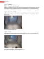
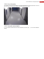
The contents of this document are provided on an "as is" basis. No representation or warranty (either
express or implied) is made as to the completeness, accuracy or reliability of the contents of this document.
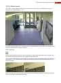
The manufacturer reserves the right to change designs or specifications without obligation and without
further notice. Except as otherwise provided, all warranties, express or implied, including without limitation
any implied warranties of merchantability and fitness for a particular purpose are expressly excluded.
Intellectual Property and Copyright
This document includes registered and unregistered trademarks. All trademarks displayed are the
trademarks of their respective owners. Your use of this document does not constitute or create a license or
any other right to use the name and/or trademark and/or label. This document is subject to copyright owned
by Xtralis AG ("Xtralis"). You agree not to copy, communicate to the public, adapt, distribute, transfer, sell,
modify or publish any contents of this document without the express prior written consent of Xtralis.
General Warning
This product must only be installed, configured and used strictly in accordance with the General Terms and
Conditions, Technical and User Manual and product documents available from Xtralis. All proper health and
safety precautions must be taken during the installation, commissioning and maintenance of the product.
The system should not be connected to a power source until all the components have been installed. Proper
safety precautions must be taken during tests and maintenance of the products when these are still
connected to the power source. Failure to do so or tampering with the electronics inside the products can
result in an electric shock causing injury or death and may cause equipment damage. Xtralis is not
responsible and cannot be held accountable for any liability that may arise due to improper use of the
equipment and/or failure to take proper precautions. Only persons trained through an Xtralis accredited
training course can install, test and maintain the system.
Liability
You agree to install, configure and use the products strictly in accordance with the User Manual and product
documents available from Xtralis.
Xtralis is not liable to you or any other person for incidental, indirect, or consequential loss, expense or
damages of any kind including without limitation, loss of business, loss of profits or loss of data arising out of
your use of the products. Without limiting this general disclaimer the following specific warnings and
disclaimers also apply:
Fitness for Purpose
You agree that you have been provided with a reasonable opportunity to appraise the products and have
made your own independent assessment of the fitness or suitability of the products for your purpose. You
acknowledge that you have not relied on any oral or written information, representation or advice given by or
on behalf of Xtralis or its representatives.
Total Liability
To the fullest extent permitted by law that any limitation or exclusion cannot apply, the total liability of Xtralis
in relation to the products is limited to:
(i) in the case of services, the cost of having the services supplied again; or
(ii) in the case of goods, the lowest cost of replacing the goods, acquiring equivalent goods or having the
goods repaired.
Indemnification
You agree to fully indemnify and hold Xtralis harmless for any claim, cost, demand or damage (including
legal costs on a full indemnity basis) incurred or which may be incurred arising from your use of the products.
Miscellaneous
If any provision outlined above is found to be invalid or unenforceable by a court of law, such invalidity or
unenforceability will not affect the remainder which will continue in full force and effect. All rights not
expressly granted are reserved.
3
4
FastTrace 2
Product Conventions
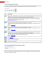
The following icons conventions are used with this product.
Convention
Description
Caution: This icon is used to indicate that there is a danger to equipment.
The danger could be loss of data, physical damage, or permanent
corruption of configuration details.
Warning: This icon is used to indicate that there is a danger of electric
shock. This may lead to death or permanent injury.
Warning: This icon is used to indicate that there is a danger of inhaling
dangerous substances. This may lead to death or permanent injury.
Tradename statement
ADPRO is a registered trademark of Xtralis AG Pty Ltd.
Contact Us
The Americas +1 781 740 2223
Asia +852 2916 8876
Australia and New Zealand +61 3 9936 7000
UK and Continental Europe +44 1442 242 330
The Middle East +962 6 588 5622
www.xtralis.com
Technical Manual | Contents
Contents
General information ........................................................................................................................................... 3
Contents ............................................................................................................................................................ 5
1
Safety instructions ................................................................................................................................... 11
2
Hardware ................................................................................................................................................. 13
2.1
FastTrace 2 versus FastTrace 2 Lite ............................................................................................... 13
2.2
FastTrace 2 versus FastTrace 2................................................................................................... 14
2.3
Technical specifications ................................................................................................................... 15
2.4
Hard disks ........................................................................................................................................ 16
2.4.1
Required hard disk capacity .................................................................................................... 16
2.4.2
The ta,smart command ............................................................................................................ 16
2.4.3
Add / Replace the hard disk..................................................................................................... 17
2.4.3.1 Material list (for 1 hard disk) ................................................................................................ 18
2.4.3.1.1 Mounting a second hard disk ......................................................................................... 19
2.4.3.1.1.1 With an Intel DH55TC motherboard ....................................................................... 19
2.4.3.1.1.2 With an Intel DH61BE motherboard ....................................................................... 21
2.4.3.1.2 Mounting a third/fourth hard disk ................................................................................... 23
2.4.3.1.2.1 With the Intel DH55TC motherboard ...................................................................... 23
2.4.3.1.2.2 With the Intel DH61BE motherboard ...................................................................... 26
2.5
Fan speed selection ......................................................................................................................... 30
2.6
Front LED indicators ........................................................................................................................ 30
2.7
Required motherboard ..................................................................................................................... 31
2.7.1
FastTrace 2 BIOS settings ....................................................................................................... 32
2.7.1.1 Motherboard Intel DG31PR or Intel DG41TY ...................................................................... 32
2.7.1.2 Motherboard Intel DH55TC .................................................................................................. 32
2.7.1.3 Motherboard Intel DH61BE.................................................................................................. 32
2.7.2
Main & Extension I/O Cards .................................................................................................... 33
2.7.2.1 How to insert the I/O card? .................................................................................................. 33
2.7.2.1.1 Inserting the I/O cards on an Intel DG31PR motherboard ............................................ 34
2.7.2.1.2 Inserting the I/O cards on an Intel DG41TY motherboard ............................................. 35
2.7.2.1.3 Inserting the I/O cards on an Intel DH55TC motherboard ............................................. 36
2.7.2.1.4 Inserting the I/O cards on an Intel DH61BE motherboard ............................................. 37
2.7.2.1.5 Reset signal ................................................................................................................... 37
2.7.2.1.6 I/O cards with mounting sets ......................................................................................... 38
2.7.2.1.6.1 Mounting order ........................................................................................................ 38
2.7.3
Replacing the motherboard ..................................................................................................... 38
2.8
Extension boards ............................................................................................................................. 39
2.8.1
Required video card ................................................................................................................. 41
2.8.1.1 Replacing a video card ........................................................................................................ 41
2.8.1.2 Adding a video card ............................................................................................................. 41
2.8.2
DTC board ............................................................................................................................... 41
2.9
Available configurations ................................................................................................................... 42
2.9.1
With Intel DG31PR motherboard ............................................................................................. 42
2.9.1.1 Network/monitor/keyboard ................................................................................................... 42
2.9.1.2 Extension slots ..................................................................................................................... 42
2.9.1.3 The Xtralis configurations .................................................................................................... 43
2.9.1.3.1 Analogue cameras (4 – 8 – 12 – 16 channels) .............................................................. 43
2.9.1.3.2 IP Cameras (8 or 16 channels) ...................................................................................... 43
2.9.1.3.3 Hybrid (12 channels)...................................................................................................... 43
2.9.1.3.4 Hybrid (16 channels)...................................................................................................... 43
2.9.2
With Intel DG41TY motherboard ............................................................................................. 44
2.9.2.1 Network/monitor/keyboard ................................................................................................... 44
2.9.2.2 Extension slots ..................................................................................................................... 44
2.9.2.3 The Xtralis configurations .................................................................................................... 45
2.9.2.3.1 Analogue cameras (4 – 8 – 12 – 16 channels) .............................................................. 45
2.9.2.3.2 IP Cameras (8 or 16 channels) ...................................................................................... 45
2.9.2.3.3 Hybrid (12 channels)...................................................................................................... 45
2.9.2.3.4 Hybrid (16 channels)...................................................................................................... 45
2.9.3
With Intel DH55TC motherboard ............................................................................................. 46
2.9.3.1 Network/monitor/keyboard ................................................................................................... 46
5
6
FastTrace 2
2.9.3.2 Extensions slots ................................................................................................................... 46
2.9.3.3 The Xtralis configurations .................................................................................................... 47
2.9.3.3.1 Analogue cameras (4 channels) .................................................................................... 47
2.9.3.3.2 Analogue cameras (8 channels) .................................................................................... 47
2.9.3.3.3 Analogue cameras (12 channels) .................................................................................. 47
2.9.3.3.4 Analogue cameras (16 channels) .................................................................................. 47
2.9.3.3.5 IP Cameras (8 or 16 channels) ...................................................................................... 48
2.9.3.3.6 Hybrid (12 channels)...................................................................................................... 48
2.9.3.3.7 Hybrid (16 channels)...................................................................................................... 48
2.9.4
With Intel DH61BE motherboard ............................................................................................. 49
2.9.4.1 Network/monitor/keyboard ................................................................................................... 49
2.9.4.2 Extensions slots ................................................................................................................... 50
2.9.4.3 The Xtralis configurations .................................................................................................... 50
2.9.4.3.1 Analogue cameras (4 channels) .................................................................................... 50
2.9.4.3.2 Analogue cameras (8 channels) .................................................................................... 50
2.9.4.3.3 Analogue cameras (12 channels) .................................................................................. 51
2.9.4.3.4 Analogue cameras (16 channels) .................................................................................. 51
2.9.4.3.5 IP Cameras (8 or 16 channels) ...................................................................................... 51
2.9.4.3.6 Hybrid (12 channels)...................................................................................................... 51
2.9.4.3.7 Hybrid (16 channels)...................................................................................................... 51
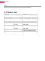
2.10 Network load .................................................................................................................................... 52
2.11 Current consumption ....................................................................................................................... 53
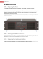
2.12 Maintenance .................................................................................................................................... 54
2.12.1
Replacing the filters ................................................................................................................. 54
2.12.2
Cleaning the FastTrace 2 server ............................................................................................. 54
2.12.3
Replacing the motherboard battery ......................................................................................... 54
3
Client Setup and Configuration ................................................................................................................ 55
3.1
Client software - minimum system requirements ............................................................................. 55
3.1.1
Hardware ................................................................................................................................. 55
3.1.2
Software ................................................................................................................................... 55
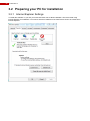
3.2
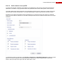
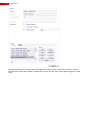
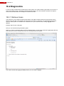
Preparing your PC for installation .................................................................................................... 56
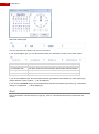
3.2.1
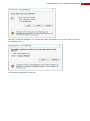
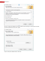
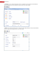
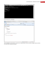
Internet Explorer Settings ........................................................................................................ 56
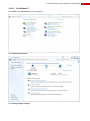
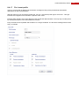
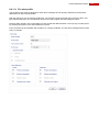
3.2.2
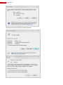
Changing the PC‟s IP address................................................................................................. 58
3.2.2.1 For Windows XP .................................................................................................................. 58
3.2.2.2 For Windows 7 ..................................................................................................................... 59
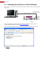
3.3
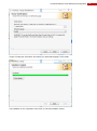
Installing the FastTrace 2 Client Software ....................................................................................... 62
3.4
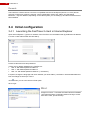
Initial configuration ........................................................................................................................... 66
3.4.1
Launching the FastTrace 2 client in Internet Explorer ............................................................. 66
3.4.2
Launching the FastTrace 2 client in its own window ............................................................... 67
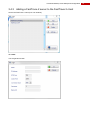
3.4.3
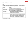
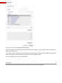
Adding a FastTrace 2 server to the FastTrace 2 client............................................................ 69
3.4.4
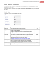
Network connections ............................................................................................................... 71
3.4.4.1 Ports ..................................................................................................................................... 71
3.4.4.2 Ethernet connection ............................................................................................................. 72
3.4.4.2.1 Configuring Dynamic DNS settings ............................................................................... 73
3.4.4.2.2 Dynamic DNS error messages ...................................................................................... 73
3.4.4.2.2.1 Warning: Unable to determine IP address.............................................................. 73
3.4.4.2.2.2 No update required ................................................................................................. 73
3.4.4.2.3 What‟s the use of using Dynamic DNS? ........................................................................ 74
3.4.4.3 Granting access to the FastTrace 2 video system .............................................................. 74
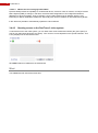
3.4.4.4 PPP connection ................................................................................................................... 75
3.4.4.4.1 PSTN or ISDN modem Configuration ............................................................................ 75
3.4.4.4.2 3G modem Configuration............................................................................................... 78
4
Using IP cameras .................................................................................................................................... 81
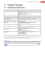
4.1
Technical specifications ................................................................................................................... 81
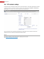
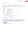
4.2
IP camera setup ............................................................................................................................... 82
4.2.1
General parameters ................................................................................................................. 84
4.2.2
Video settings .......................................................................................................................... 84
4.2.2.1 Color .................................................................................................................................... 84
4.2.2.2 Overlay................................................................................................................................. 85
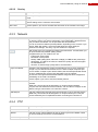
4.2.3
Network .................................................................................................................................... 85
4.2.4
PTZ .......................................................................................................................................... 85
4.2.5
Recording................................................................................................................................. 86
4.3
Update and configure the HIPI card ................................................................................................ 87
Technical Manual | Contents
5
6
7
8
4.4
Supported IP cameras ..................................................................................................................... 89
4.5
Video streams .................................................................................................................................. 90
Using analogue cameras ......................................................................................................................... 93
5.1
Technical specifications ................................................................................................................... 93
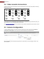
5.2
Video & Audio Connections ............................................................................................................. 94
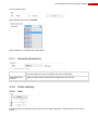
5.3
Camera Configuration ...................................................................................................................... 94
5.3.1
General parameters ................................................................................................................. 95
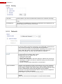
5.3.2
Video settings .......................................................................................................................... 95
5.3.2.1 Color .................................................................................................................................... 95
5.3.2.2 Overlay................................................................................................................................. 96
5.3.3
Network .................................................................................................................................... 96
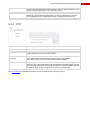
5.3.4
PTZ .......................................................................................................................................... 97
5.3.5
Recording................................................................................................................................. 98
5.4
PTZ settings ..................................................................................................................................... 99
5.4.1
Serial PTZ ................................................................................................................................ 99
5.4.2
Serial PTZ on MIO card ......................................................................................................... 100
5.4.3
DTC PTZ ................................................................................................................................ 101
5.4.4
List of available PTZ protocols............................................................................................... 102
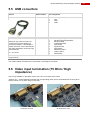
5.5
USB convertors .............................................................................................................................. 103
5.6
Video input termination (75 Ohm / High impedance)..................................................................... 103
Audio ...................................................................................................................................................... 105
6.1
Audio IN ......................................................................................................................................... 105
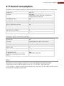
6.1.1
Recommended microphones ................................................................................................. 105
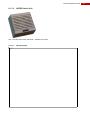
6.1.1.1 Crown all-weather PZM-11LLWR ...................................................................................... 105
6.1.1.1.1 Specifications ............................................................................................................... 105
6.1.1.1.2 Wiring diagram ............................................................................................................. 106
6.1.1.2 ADPRO microphones IMUSTD; IMUPIR; IMUTEMP ........................................................ 106
6.1.1.2.1 Specifications ............................................................................................................... 106
6.1.1.2.2 Wiring diagram ............................................................................................................. 106
6.1.1.3 ADPRO Audio Unit ............................................................................................................ 107
6.1.1.3.1 Wiring diagram ............................................................................................................. 107
6.2
Audio OUT ..................................................................................................................................... 108
6.2.1
Connecting the VM22A audio switch to the FastTrace 2 video system ................................ 110
I/O Cards Configuration ......................................................................................................................... 111
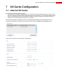
7.1
Internal I/O Cards .......................................................................................................................... 111
7.1.1
Update Main I/O card ............................................................................................................. 113
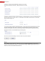
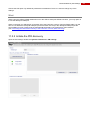
7.1.2
USB I/O address range .......................................................................................................... 114
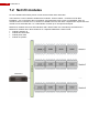
7.2
Net I/O modules ............................................................................................................................. 116
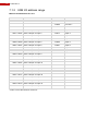
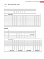
7.2.1
Net I/O address range ........................................................................................................... 117
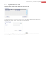
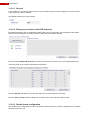
7.2.2
Adding Net I/O module with known IP address ..................................................................... 118
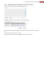
7.2.3
Searching Net I/O modules on the local network .................................................................. 119
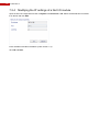
7.2.4
Modifying the IP settings of a Net I/O module ....................................................................... 120
7.2.5
Net I/O module inputs & outputs setup .................................................................................. 121
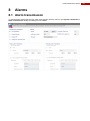
Alarms .................................................................................................................................................... 123
8.1
Alarm transmission ........................................................................................................................ 123
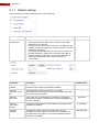
8.1.1
Default settings ...................................................................................................................... 124
8.1.2
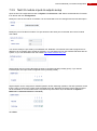
Primary alarm transmission settings ...................................................................................... 125
8.1.3
Secondary alarm transmission settings ................................................................................. 126
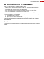
8.2
Arming/Disarming the video system .............................................................................................. 127
8.2.1
Arm/Disarm schedule ............................................................................................................ 128
8.2.2
Arm/Disarm Switch ................................................................................................................ 129
8.3
Alarm inputs ................................................................................................................................... 130
8.3.1
PTZ via I/O ............................................................................................................................. 133
8.3.2
Connecting fire detectors ....................................................................................................... 134
8.3.2.1 Fire reset input and output ................................................................................................. 135
8.3.3
IntrusionTrace alarms ............................................................................................................ 136
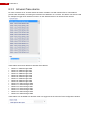
8.4
Alarm profiles ................................................................................................................................. 137
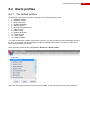
8.4.1
The default profiles ................................................................................................................ 137
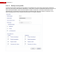
8.4.1.1 Normal event profile ........................................................................................................... 138
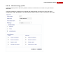
8.4.1.2 Primary event profile .......................................................................................................... 139
8.4.1.3 Backup event profile .......................................................................................................... 140
8.4.1.4 Silent message profile ....................................................................................................... 141
7
8
FastTrace 2
8.4.1.5 Single event profile ............................................................................................................ 142
8.4.1.6 Active sensor event profile ................................................................................................. 143
8.4.1.7 Fire1 event profile .............................................................................................................. 145
8.4.1.8 Fire2 event profile .............................................................................................................. 146
8.4.1.9 Non-fire alarm profile ......................................................................................................... 147
8.4.1.10
Fire action profile ........................................................................................................... 148
8.4.1.11
Fire alert profile .............................................................................................................. 149
8.4.1.12
Fire trouble profile .......................................................................................................... 150
8.4.2
Adding a new profile .............................................................................................................. 151
8.5
Email server settings ..................................................................................................................... 153
8.5.1
Email address book ............................................................................................................... 153
9
Activate outputs ..................................................................................................................................... 155
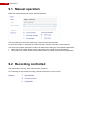
9.1
Manual operation ........................................................................................................................... 156
9.2
Recording controlled ...................................................................................................................... 156
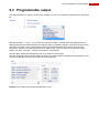
9.3
Programmable output .................................................................................................................... 157
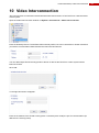
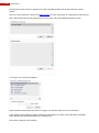
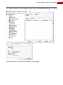
10
Video Interconnection ........................................................................................................................ 159
11
PIR settings........................................................................................................................................ 163
11.1 Required PIR firmware .................................................................................................................. 163
11.2 Connecting the PIRs ...................................................................................................................... 163
11.2.1
Connecting the PIR detector directly to the FastTrace 2 server (Main I/O card) .................. 164
11.2.2
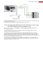
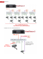
Connecting the PIR detector to the FastTrace 2 server using the USB to RS485 8 channel
distribution unit ....................................................................................................................... 165
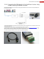
11.2.3
Connecting the PIR detector to the FastTrace 2 server using a USB to serial port RS485
converter ................................................................................................................................ 167
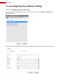
11.3 Configuring the software setting .................................................................................................... 168
11.3.1
Configuring the serial port ...................................................................................................... 168
11.3.2
Initiate the PIR discovery ....................................................................................................... 169
11.3.2.1
General .......................................................................................................................... 170
11.3.2.2
Discovery and status of the PIR detectors .................................................................... 170
11.3.2.3
Double knock configuration ........................................................................................... 170
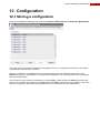
12
Configuration...................................................................................................................................... 171
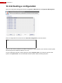
12.1 Storing a configuration ................................................................................................................... 171
12.2 Activating a configuration ............................................................................................................... 172
13
Configuring analytics ......................................................................................................................... 173
TM
13.1 FastTrace 2 IntrusionTrace ........................................................................................................ 173
13.1.1
About the FastTrace 2 Perimeter Detection analytic ............................................................. 173
13.1.2
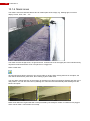
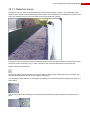
Scope ..................................................................................................................................... 174
13.1.2.1
Suitable scenes.............................................................................................................. 174
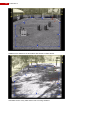
13.1.2.2
Unsuitable scenes.......................................................................................................... 175
13.1.3
Camera .................................................................................................................................. 176
13.1.3.1
Resolution and frame rate ............................................................................................. 176
13.1.3.2
Field of view (FOV) ........................................................................................................ 176
13.1.3.3
Position .......................................................................................................................... 176
13.1.4
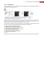
Configuration.......................................................................................................................... 177
13.1.4.1
Perimeter configuration interface ................................................................................... 177
13.1.4.2
Cameras section ............................................................................................................ 177
13.1.4.3
Drawing Tools section ................................................................................................... 178
13.1.4.4
Select IntrusionTrace license section ............................................................................ 178
13.1.4.5
Info section ..................................................................................................................... 179
13.1.4.6
Advanced parameters profile section ............................................................................ 179
13.1.4.6.1 Profile details ............................................................................................................. 180
13.1.4.6.2 Tips for advanced parameters setting ....................................................................... 188
13.1.4.6.3 Adding a new detection profile .................................................................................. 188
13.1.4.7
Save button .................................................................................................................... 188
13.1.5
Calibration .............................................................................................................................. 189
13.1.6
Mask zones ............................................................................................................................ 190
13.1.7
Detection zones ..................................................................................................................... 191
13.1.8
Trigger lines ........................................................................................................................... 192
13.1.8.1
Some examples ............................................................................................................. 193
TM
13.2 FastTrace 2 LoiterTrace ............................................................................................................. 195
13.2.1
About the FastTrace 2 LoiterTrace (Loitering Detection analytic) ......................................... 195
13.2.2
Scope ..................................................................................................................................... 195
13.2.3
Camera .................................................................................................................................. 196
Technical Manual | Contents
13.2.3.1
Resolution and frame rate ............................................................................................. 196
13.2.3.2
Field of View (FOV)........................................................................................................ 196
13.2.3.3
Position .......................................................................................................................... 196
13.2.3.4
Scene illumination .......................................................................................................... 197
13.2.3.5
Automatic camera adaption ........................................................................................... 197
13.2.4
Configuration.......................................................................................................................... 198
13.2.4.1
Loitering configuration interface..................................................................................... 198
13.2.4.2
Cameras section ............................................................................................................ 198
13.2.4.3
Drawing Tools section ................................................................................................... 199
13.2.4.4
Select LoiterTrace license ............................................................................................. 199
13.2.4.5
Loitering parameters ...................................................................................................... 200
13.2.4.6
Info section ..................................................................................................................... 200
13.2.4.7
Save button .................................................................................................................... 200
13.2.5
Mask zones ............................................................................................................................ 201
13.2.6
Detection zones ..................................................................................................................... 202
13.2.6.1
Samples ......................................................................................................................... 203
13.3 Motion & Sabotage ........................................................................................................................ 206
13.3.1
Motion Detection Interface ..................................................................................................... 206
13.3.2
Private zones ......................................................................................................................... 206
13.3.3
Sabotage detection ................................................................................................................ 208
13.3.4
Motion detection .................................................................................................................... 209
14
Active connections ............................................................................................................................. 211
15
Log ..................................................................................................................................................... 213
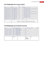
15.1 Example of a Log record ................................................................................................................ 215
15.2 Example of an Event record .......................................................................................................... 215
15.3 Example of a Command record ..................................................................................................... 216
16
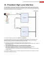
Presidium High Level Interface .......................................................................................................... 217
17
Firmware, license, configuration ........................................................................................................ 219
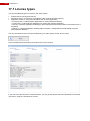
17.1 License types ................................................................................................................................. 220
17.2 System license ............................................................................................................................... 222
17.3 Application license ......................................................................................................................... 223
17.3.1
IntrusionTrace ........................................................................................................................ 224
17.3.2
LoiterTrace ............................................................................................................................. 224
17.3.3
Fire-IO .................................................................................................................................... 224
17.3.4
PIR-HLI .................................................................................................................................. 224
17.4 Checking the software version ....................................................................................................... 225
17.4.1
Upgrade the Client version to the Server version .................................................................. 225
17.4.2
Downloading the new client software version from the Xtralis Support website. .................. 225
17.5 Installation of the FastTrace 2 firmware ........................................................................................ 226
17.5.1
Installation requirements ........................................................................................................ 226
17.5.2
Installation procedure ............................................................................................................ 226
17.6 Upgrade the FastTrace 2 firmware ................................................................................................ 228
17.6.1
Upgrade requirements ........................................................................................................... 228
17.6.2
Downloading a new firmware version from the Xtralis Support website. .............................. 228
17.6.3
Upgrade procedure ................................................................................................................ 229
17.6.3.1
Upgrade firmware with BIN file ...................................................................................... 229
17.6.3.2
Upgrade firmware with img file ...................................................................................... 232
17.6.4
IP camera definitions ............................................................................................................. 233
18
Additional information ........................................................................................................................ 235
18.1 Retrieving the IP address of the FastTrace 2 ................................................................................ 235
18.2 Diagnostics .................................................................................................................................... 236
18.2.1
Retrieve traces ....................................................................................................................... 236
18.2.2
Retrieve reports ..................................................................................................................... 239
18.2.3
VSKWin: retrieve the FastTrace 2 configuration file .............................................................. 240
18.2.4
VSKWin: Create an alarm text that automatically opens a live camera image ..................... 241
18.2.5
Activate timer output on FastTrace 2 ..................................................................................... 241
18.3 Error codes .................................................................................................................................... 242
18.3.1
General error codes ............................................................................................................... 242
18.3.2
Control protocol error codes .................................................................................................. 243
18.3.3
Filter graph/codec error codes ............................................................................................... 244
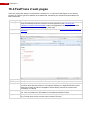
18.4 FastTrace 2 web pages ................................................................................................................. 246
19
Labelling of products .......................................................................................................................... 247
9
10
FastTrace 2
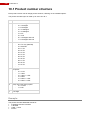
19.1
19.2
Product number structure .............................................................................................................. 248
Declaration of Conformity .............................................................................................................. 249
Technical Manual | Safety instructions
1
Safety instructions
CAUTION
RISK OF ELECTRIC
SHOCK, DO NOT OPEN!
CAUTION: TO REDUCE THE RISK OF ELECTRICAL SHOCK, DO NOT REMOVE COVERS. NO USER SERVICEABLE
PARTS INSIDE. REFER SERVICING TO QUALIFIED SERVICE PERSONNEL.
WARNING: TO REDUCE THE RISK OF FIRE OR ELECTRIC SHOCK, DO NOT EXPOSE THIS
APPLIANCE TO RAIN OR MOISTURE.
The lightning flash with an arrowhead symbol within an equilateral triangle is intended to
alert the user to the presence of non-insulated “dangerous voltage” within the product‟s
enclosure that may be of sufficient magnitude to constitute a risk of electric shock to
persons.
The exclamation mark within an equilateral triangle is intended to alert the user to
presence of important operating and maintenance (servicing) instructions in the literature
accompanying this appliance.
Environmental information
The crossed-out container indicates the fact that within the European Union this
product has to be offered for separate waste collection at the end of the product‟s
lifespan. This goes for the product, but also for all accessories that are included and
bear the same label. Do not put these products with domestic garbage.
For more information about the ways to collect, reuse en recycle, please contact your
local Waste Service. You can also contact Xtralis for more information about the
environmental aspects of our products.
Clarification
ADPRO‟s FastTrace 2 is the newest ADPRO product concerning video recording. Hence, FastTrace 2 is
also compatible with:
FastTrace
V3100
V3100 FT
V3100 HYBRID
You can upgrade firmware and software of the products mentioned above to the newest FastTrace 2
firmware and software. Please do take into consideration that the FastTrace 2 video system could have other
system requirements than any other previous ADPRO products!
11
12
FastTrace 2
Technical Manual | Hardware
2
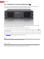
Hardware
2.1 FastTrace 2 versus FastTrace 2 Lite
The FastTrace 2 Lite has been designed, developed and manufactured as a complete FastTrace 2 video
security system, but the ENTRY system license that is included, limits the number of cameras that can be
supported to a maximum of 4 analogue cameras.
Please also note that the FastTrace 2 Lite can only operate on analogue cameras, there is no possibility to
support IP cameras.
The FastTrace 2 Lite can only be purchased with an entry system license:
Full system license
TX (transmission) only license
Entry level license
FastTrace 2
FastTrace 2 Lite
See System license for further information on the system licenses.
Please consult the ADPRO commercial data sheet on the FastTrace 2 Lite. This data sheet can be
downloaded from our website www.xtralissecurity.com. You don‟t need to login to download the commercial
data sheets!
13
14
FastTrace 2
2.2 FastTrace 2 versus FastTrace 2
®
TM
The FastTrace 2 is the newest hardware in the ADPRO FastTrace series. It has been developed as a
more powerful video system with higher performance and more efficient operation.
The most important difference is the possibility to have 16 analytic channels with the FastTrace 2, while
the FastTrace 2 is limited to a maximum of 4 analytic streams.
The FastTrace 2 can also be purchased with a full or tx only system license:
Full system license
TX (transmission) only license
Entry level license
FastTrace 2
FastTrace 2
See System license for further information on the system licenses.
Mind:
The FastTrace 2 requires the minimal software version 2.6!
Please note:
Wherever in this document the term FastTrace 2 is used, you can assume that the term refers to both the
FastTrace 2 and the FastTrace 2, unless specifically mentioned otherwise!
Technical Manual | Hardware
2.3 Technical specifications
Operating system
PC platform – Linux OS
Network protocols
TCP, UDP, FTP, TELNET, HTTP, SMTP, RTSP, RTP
Bandwidth
Remotely adjustable: compression, fps and quality.
A bandwidth limit can be specified.
Bandwidth consumption
6 fps CIF/SIF: 70 kb/sec
12 fps 4CIF/SIF: 400 kb/sec in optimal quality
Software updates
Local and remote
Maximum number of cameras
16 (total of analogue and IP cameras)
Web server
Integrated
COM ports
4 USB interfaces used for:
- PTZ control (requires USB RS485 convertor)
- PSTN or ISDN modem
Ethernet
10/100/1000 Base-T, auto detection, full duplex, RJ45
Storage
up to 4 devices (connected through SATA interfaces);
following arrangements are possible:
- 1 to 4 hard disks (500 GB to 2 TB)
Remark: There are USB connectors accessible on the back of the
FastTrace 2 video system; and also 1 USB connector is on the front
to which a portable DVD writer can be connected to export video
sequences.
Remote visualisation
Internet Explorer; Windows XP, Windows Vista, Windows 7,
Windows Server 2003, Windows Server 2008
Management
-
Power supply
100~240 VAC, 50/60 Hz (+80% efficiency)
! The video system has to be connected to a 230 VAC/16A
mains outlet with proper earth, applying a separate locally
approved power cord.
Operating temperature
5 – 40°C (see also Fan speed selection)
Humidity
20 – 93% (non condensing)
Dimensions
445x132,50x300 (WxHxD in mm)
Rubber feet can be fixed on the bottom. The height is then
increased with 2.5 mm.
Internet Explorer (installs Client software)
VSKwin software
M3000 software
VideoCentral Platinum
3rd party CMS software
Multi-site FASTTRACE 2 configuration is possible:
Integration of up to 10,000 FastTrace 2 video security systems.
Remote video and audio, live video and consultation of recordings.
Compatible with FOXnet®Plus, FALCONnet, S3100, Presidium, VSKwin®, VCP and M3000.
SDK for third party integration.
15
16
FastTrace 2
2.4 Hard disks
2.4.1 Required hard disk capacity
As there are lots of configuration possibilities, a hard disk space calculator has been made available. You
can find this hard disk space calculator on the CD/DVD provided with your FastTrace 2 video system, or you
can download it from our website http://www.xtralissecurity.com. Make sure you log in with sufficient
download rights!
Mind:
The calculator is an estimating tool only. Figures are purely indicative. The real results of the hard disk
capacity depend on scene content.
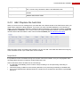
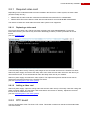
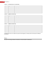
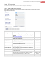
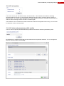
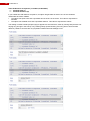
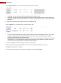
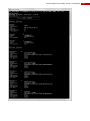
2.4.2 The ta,smart command
SMART stands for Self-Monitoring Analysis and Reporting Technology. When executing the ta,smart
command in a TELNET session, you will become the SMART information for all hard disks in the video
system FastTrace 2.
Device
Power status
Smart status
Temperature
Indicates the specific hard disk
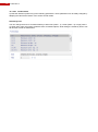
The power status column can display 1 of these statuses:
> ERROR problem retrieving power status of the drive
> ACTIVE/IDLE normal operation of the drive
> STANDBY drive is in low power mode (drive has spun down)
> SLEEPING drive is in lowest power mode (drive is completely shut
down)
The smart status column can display 1 of these statutes:
> ERROR drive is failing
> ALERT there‟s a problem retrieving smart info from the drive or the
drive could start having trouble
> NORMAL no problems found with the drive
The temperature column display from left to right:
> the minimum temperature of the disk
> the current temperature of the disk
> the maximum temperature of the disk
Technical Manual | Hardware
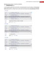
Force [ON/OFF]
Interval
Temperature threshold
ON = smart is checked on disk in STANDBY or SLEEPING mode;
OFF = smart is only checked on disks in ACTIVE/IDLE mode
Indicates the interval time between smart checks. The value is expressed in
minutes.
if disk temp is higher than this threshold, an alarm is generated: I102:
'SMART HDD ALERT TEMP'
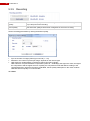
2.4.3 Add / Replace the hard disk
When you receive an error message from your hard disk in the Status window of the FastTrace 2 Client, you
might need to replace the faulty hard disk. If you have 2 or more hard disks installed in your FastTrace 2
server, you can check which hard disk is causing the alarm messages in the FastTrace 2 Client via System
> Maintenance > Harddisks. In the column Smart you will get the operational status of the hard disks. You
can also retrieve this information via the Telnet command ta,smart (see The ta,smart command).
Switch off power supply and replace the hard disk. You can also add a new hard disk without removing any
of the hard disks in use. Up to 4 hard disks can be installed.
Important:
It is possible to mount a hard disk coming from another unit into the installer. Thus you can playback video
recordings that have been recorded by another FastTrace 2 unit.
Some restrictions need to be taken into account though:
It is advised to immediately put the number of days recording to 0, thus preventing overwriting of
valuable data.
Clear all recording conditions in the recording behaviour, thus preventing overwriting of valuable data.
Do not mix hard disks from different FastTrace 2 units into one, because this will result in unpredictable
behaviour.
17
18
FastTrace 2
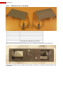
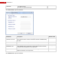
2.4.3.1
Material list (for 1 hard disk)
Part
Support for disk 2
Support for disk 3 and 4
Disk screws
Dented washers M4
Mounting screws
Sata cable
Amount + reference number
1x #17291210
1x #17291220
4x #17434080 or #17434060
4x #17720050
4x #17439080
1x #16520870 (for DH55TC motherboard)
1x #16520875 (for DH61BE motherboard)
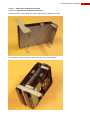
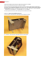
Remove the lid. Then remove the front plate. You can now see the mounting holes for the disk bays.
Install the internal disk(s) into the supports with screws # 17434080 or # 17434060 and dented washers M4
# 17720050.
Technical Manual | Hardware
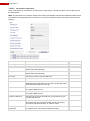
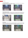
2.4.3.1.1
2.4.3.1.1.1
Mounting a second hard disk
With an Intel DH55TC motherboard
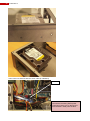
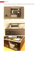
Fix the second disk onto the support at the power supply side.
Next, install the support with the screws (# 17439080) at the front and on the left side of the casing.
19
20
FastTrace 2
Then connect to eSATA2 with the SATA cable (# 16520870).
eSATA 2
Attention:
Connect the remaining SATA power
connector (not the one on the tail end
from the disk 1 cable) onto the disk.
Technical Manual | Hardware
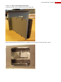
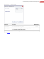
2.4.3.1.1.2
With an Intel DH61BE motherboard
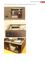
Fix the second disk onto the support at the power supply side.
Next, install the support with the screws (# 17439080) at the front and on the left side of the casing.
21
22
FastTrace 2
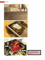
Then connect to SATA1 with the SATA cable (# 16520875).
SATA 1
SATA 6GA
SATA 0
Attention:
Connect the remaining SATA
power connector (not the one on
the tail end from the disk 1 cable)
onto the disk.
Technical Manual | Hardware
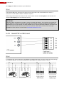
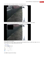
2.4.3.1.2
2.4.3.1.2.1
Mounting a third/fourth hard disk
With the Intel DH55TC motherboard
Fix the third disk on the topside of the third support (mount before the fourth).
Fix – if desired – the fourth disk on the bottom side of the same support.
23
24
FastTrace 2
Install the support with two screws (# 17439080) at the front and on the right side of the casing.
Technical Manual | Hardware
Then connect disk 3 to eSATA4 connector with the SATA cable (# 16520870).
When disk 4 is in use connect it to eSATA5 connector with the SATA cable (# 16520870).
eSATA4
eSATA5
Pay attention: Do not bend the SATA cables too sharp to avoid cable damage!
Use tie-wraps to bundle the unused SATA power cables.
25
26
FastTrace 2
Then fix the front plate (# 17011610) on the base with the screws (# 17444080).
Put the cover in place and secure with 10 screws (# 17439080).
Connect monitor/screen and keyboard to the FastTrace 2 Server. Switch on power supply and wait for the
boot window. Select <FastTrace 2 Installer> during startup. Next, select Update current system > Manage
recording disks and select the new hard disk from the list. Press ‟Enter‟. Then select – use the TAB button
– “Format and use selected disk”. Select Main Menu and choose Reboot.
The video system will now reboot. After rebooting the new hard disk can be used.
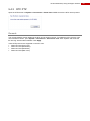
2.4.3.1.2.2
With the Intel DH61BE motherboard
Fix the third disk on the topside of the third support (mount before the fourth).
Fix – if desired – the fourth disk on the bottom side of the same support.
Technical Manual | Hardware
Install the support with two screws (# 17439080) at the front and on the right side of the casing.
27
28
FastTrace 2
Then connect disk 3 to SATA2 connector with the SATA cable (# 16520875).
When disk 4 is in use connect it to SATA3 connector with the SATA cable (# 16520875).
SATA 0
Pay attention: Do not bend the SATA cables too sharp to avoid cable damage!
Use tie-wraps to bundle the unused SATA power cables.
Then fix the front plate (# 17011610) on the base with the screws (# 17444080).
Put the cover in place and secure with 10 screws (# 17439080).
Technical Manual | Hardware
Connect monitor/screen and keyboard to the FastTrace 2 Server. Switch on power supply and define the
BIOS settings for the FastTrace 2: choose Boot and then Exit (see FastTrace 2 BIOS settings). Wait for the
boot window. Select <FastTrace 2 Installer> during startup. Next, select Update current system > Manage
recording disks and select the new hard disk from the list. Press ‟Enter‟. Then select – use the TAB button
– “Format and use selected disk”. Select Main Menu and choose Reboot.
The video system will now reboot. After rebooting the new hard disk can be used.
Mind:
When using the ENTRY system license, only 1 hard disk can be used! This is for instance the case with the
ADPRO FastTrace 2 Lite.
29
30
FastTrace 2
2.5 Fan speed selection
Two large fans are provided to dissipate the heat. The fans have a switch to select the speed: low, medium
or fast. Whatever the ambient temperature, the fan speed may be set to medium. Only with extreme ambient
temperatures the fan speed should be adapted.
2.6 Front LED indicators
On the front of the FastTrace 2 video system are 3 LEDs:
Green LED
Power is on
Yellow LED (*)
Fault
Blue LED
Storage media activity
Only the green and blue LED could be lit all the time. If you see the yellow LED lit, you should check the
status of your FastTrace 2 video system.
(*) The yellow LED can only be lit when a Main I/O card has been installed.
Remark:
When the 3 LEDs are flashing simultaneously, the system is busy updating the recording discs. Do not turn
off power in that case!
Technical Manual | Hardware
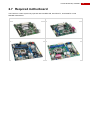
2.7 Required motherboard
The FastTrace 2 video system only operates with Intel DG31PR, Intel DG41TY, Intel DH55TC or Intel
DH61BE motherboard.
Intel DG31PR motherboard
Intel DG41TY motherboard
Intel DH55TC motherboard
Intel DH61BE motherboard
31
32
FastTrace 2
2.7.1 FastTrace 2 BIOS settings
2.7.1.1
Motherboard Intel DG31PR or Intel DG41TY
Choose Main > System Time to set the system time.
Choose Main > System Date to set the system date.
Choose Advanced > Numlock and select the option „Off‟.
Choose Power > After Power Failure and select the option „Power-On‟.
Choose Boot > Boot USB Devices First and select the option „Enable‟.
Choose Exit > Exit & Save Changes and select the option „Yes‟.
All other parameters can be left to the default settings!
2.7.1.2
Motherboard Intel DH55TC
Choose Main > System Time to set the system time.
Choose Main > System Date to set the system date.
Choose Advanced > Boot > Numlock and select the option „Off‟.
Choose Advanced > Drive Configuration > Smart and select the option „Disable‟.
Choose Advanced > Drive Configuration > Config AHCI and select the option „On‟.
Choose Advanced > Event log > Event logging and select the option „Disable‟.
Choose Advanced > Chipset Configuration > HPET and select the option „Disable‟.
Choose Power > After Power Failure and select the option „Power-On‟.
Choose Exit > Exit & Save Changes and select the option „Yes‟.
All other parameters can be left to the default settings!
2.7.1.3
Motherboard Intel DH61BE
Choose Main > System Time to set the system time.
Choose Main > System Date to set the system date.
Choose Configuration > SATA drives > Smart and select the option „Disable‟.
Choose Configuration > SATA drives > Chipset SATA mode and select the option „AHCI‟.
Choose Configuration > Event log > Event logging and select the option „Disable‟.
Choose Power > After Power Failure and select the option „Power-On‟.
Choose Boot > Hard drive order and place the DOM „CSS HSV40-256M‟ at the top of the list, using the
arrows to select the DOM and the + key to move the selected DOM upwards. Press „Enter‟.
Choose Exit > Exit & Save Changes and select the option „Yes‟.
All other parameters can be left to the default settings!
Important:
The BIOS settings need to be reset every time a hard disk is replaced or added with the Intel DH61BE
motherboard!
Technical Manual | Hardware
2.7.2 Main & Extension I/O Cards
The OTB (On the board) I/O cards are internal I/O cards, to be fitted inside the ADPRO FastTrace 2 system.
These I/O cards offer:
8 tamper protected inputs and 4 relay outputs (rated 30VDC @ 1A) on Main IO board;
12 tamper protected inputs and 4 relay outputs on Extension IO board;
driver for PTZ cameras (half/full duplex RS485) or audio module / VM22A audio switcher (selected by
straps on the card);
driver for front LED indicators on FastTrace 2 model;
auto-detected cards on FastTrace 2 system.
You can configure 2 sets maximum on the FastTrace 2:
only Main I/O
Main I/O + Extension I/O
2 x Main I/O + Extension I/O
2 x Main I/O + 2 x Extension I/O
2.7.2.1
How to insert the I/O card?
The first set is inserted in the two furthermost slots (= nearest to the power supply) and fixed to the chassis
applying the L shaped brackets. The Main I/O card is inserted in the furthermost slot (= slot 6).
The second set is inserted in the PCI or PCI Express slots using the included PCI or PCI Inserters.
Depending on the type of motherboard, you will need either a PCI or PCI Express Inserter.
Please also consult the technical data sheet on the Main & Extension I/O cards. (document reference
19531920)
The reference numbers are the numbers you need for ordering with Xtralis.
33
34
FastTrace 2
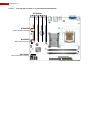
2.7.2.1.1
Inserting the I/O cards on an Intel DG31PR motherboard
#17439030
#16540280
AUDIO (to Main I/O board)
#16540260
USB (to Main I/O board)
#21760401
Reset (from Main IO board)
Intel DG31PR motherboard
Technical Manual | Hardware
2.7.2.1.2
Inserting the I/O cards on an Intel DG41TY motherboard
#17439030
#16500660
#16540280
AUDIO (to Main I/O board)
#16540260
USB (to Main I/O board)
#21760401
Reset (from Main IO board) +
Intel DG41TY motherboard
Mind:
An audio connector adapter (#16500660) is required with the Intel DG41TY motherboard to connect the flat
cable to the motherboard. You need to order this audio connector adapter separately.
35
36
FastTrace 2
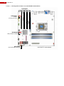
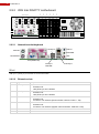
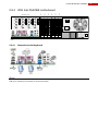
2.7.2.1.3
Inserting the I/O cards on an Intel DH55TC motherboard
#17439030
#16540280
AUDIO
(to Main I/O board)
#16540260
USB (to Main I/O board)
+
#21760401
Reset (from Main IO board)
Intel DH55TC motherboard
Technical Manual | Hardware
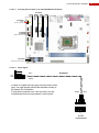
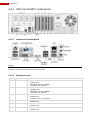
2.7.2.1.4
Inserting the I/O cards on an Intel DH61BE motherboard
#17439030
#16540280
AUDIO
(to Main I/O board)
#16500660
#16540260
USB (to Main I/O board)
#21760401
Reset (from Main IO board)
2.7.2.1.5
Reset signal
Grey
#21760401
OUT
GND
White
White
Grey
GND
IN
In case of a cable with two grey-coloured wires (older
type), the right polarity should be checked visually or
by means of a multimeter.
A reversed connection won‟t do any harm, but the
motherboard receives a permanent reset signal!
INTEL
motherboard
37
38
FastTrace 2
2.7.2.1.6
2.7.2.1.6.1
I/O cards with mounting sets
Mounting order
Remove the two cables connecting the LED board on the front to the motherboard. The LEDs will be
st
powered from the Main I/O card (of the 1 set) when installing an I/O card. Insert the flat cable #21760101 in
place of the removed cables.
Before inserting the I/O cards into the motherboard, make sure you have connected all necessary cables to
plug in the card into the motherboard. Remove any superfluous blind brackets.
2.7.3 Replacing the motherboard
The FastTrace 2 Server‟s motherboard should not be replaced in the field. When replacement of the
motherboard is required, please send back the FastTrace 2 unit to your supplier.
Technical Manual | Hardware
2.8 Extension boards
Type
HIPI
4ch/8ch
DS40xx
4ch/8ch
DS42xx
Main I/O
Extension I/O
HIPI
Description
PCI Express extension board for 8 IP cameras.
See also technical data sheet 19531930 – HIPI card.
PCI extension board for 4 or 8 analogue cameras, including audio inputs per camera
Note: these PCI Cards are to be used on an Intel DG31PR or Intel DG41TY
motherboard!
PCI EXPRESS extension board for 4 or 8 analogue cameras, including audio inputs
per camera
Note: these PCI Express Cards are to be used on an Intel Intel DH55TC
motherboard!
Main Input Output board: USB extension card, inserted in a free PCI or PCI Express
connector.
See also technical data sheet 19531920 – Main & Extension I/O Cards.
Extension Input Output board: extension board, inserted in a free PCI of PCI Express
connector and linked to the Main I/O board, extending the number of inputs and
outputs.
See also technical data sheet 19531920 – Main & Extension I/O Cards.
EIO
MIO
0V
OUT5
OUT6
OUT6
OUT8
IN19
IN20
0V
TA/STROBE
TB/AUDIO OUT
IN4
0V
0V
IN7
IN8
0V
OUT2
OUT2
OUT3
OUT3
OUT4
OUT4
CHANNEL 1…...4
OUT7
OUT7
OUT8
OUT1
OUT1
0V
IN3
CHANNEL 1…...4
IN16
IN2
CHANNEL 5…...8
0V
IN15
IN5
IN6
21 22 23 24 25
46 47 48 49 50
IN17
IN18
IN14
13 14 15 16 17 18 19 20
38 39 40 41 42 43 44 45
OUT5
0V
IN1
7 8 9 10 11 12
32 33 34 35 36 37
IN13
0V
IN11
IN12
1 2 3 4 5 6
26 27 28 29 30 31
ETHERNET
IN9
IN10
8 Ch
4 Ch
0V
RA/CLOCK
RB/DATA
Please consult the ADPRO FastTrace 2 field alerts #1 and #2 for detailed information on upgrading older
versions to the newest firmware!
39
40
FastTrace 2
General rules
The FastTrace 2 Video System offers 6 extension slots:
On Intel DG31PR and Intel DG41TY motherboards: two PCI Express slots, two PCI slots and two
physical slots.
On Intel DH55TC and Intel DH61BE motherboards: three PCI Express slots, one PCI slot and two
physical slots.
The HIPI cards can only be inserted in a PCI Express slot.
The A/V cards type DS40xx require a PCI slot. The A/V cards type DS42xx require a PCI Express slot. They
also require different types of motherboard, so a mixture of DS40xx and DS42xx cards is not possible!
Main I/O and Extension I/O cards can be inserted anywhere (in any free slot left unused); the MIO card is
connected to an internal USB connector and the EIO card is connected to the MIO card through a flat cable.
Technical Manual | Hardware
2.8.1 Required video card
Depending on the motherboard that has been installed in the FastTrace 2 video system, the video cards
(encoder cards) can vary:
DS40xx-HCI encoder cards are used with Intel DG31PR and Intel DG41TY motherboards.
DS42xx-HFVI-E encoder cards are used with the Intel DH55TC and Intel DH61BE motherboards.
The mixture of these two cards within the same video system is not supported!
2.8.1.1
Replacing a video card
First check your license (via a Telnet connection executing the command ta,license). If no license
information is listed, your license may have been deleted (by accident). Contact your dealer for a new
license.
(see also License types)
Trace the faulty video card by checking LIVE images of the connected cameras in the FastTrace 2 Client.
Switch off power supply and remove the faulty video card. Insert the new video card in the slot where you
removed the old one. It is recommended to return the faulty video card to your reseller!
Switch on power supply and reboot the video system. The replacement part will include a new license.
Upload the received license file to the FastTrace 2 Server.
(see also Uploading files to the video system)
2.8.1.2
Adding a video card
Switch off power supply. Open the casing and insert the new video card (in a free slot). Close the casing and
switch on power supply. The new video card will include a new license on delivery. Upload the received
license file to the FastTrace 2 Server.
(see also Uploading files to the video system)
2.8.2 DTC board
The DTC board offers „Down The Coax‟ PTZ control. This board is inserted on the back of the audio/video
connection board.
41
FastTrace 2
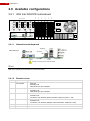
2.9 Available configurations
V1
V13
A9
V12
V16
GND
Slot 6
Slot 5
21 22 23 24 25
A16
V15
GND
13 14 15 16 17 18 19 20
V11
7 8 9 10 11 12
V8
GND
A15
GND
1 2 3 4 5 6
V4
V7
GND
46 47 48 49 50
A12
GND
V14
A11
GND
38 39 40 41 42 43 44 45
GND
32 33 34 35 36 37
V10
A8
26 27 28 29 30 31
A7
GND
21 22 23 24 25
GND
13 14 15 16 17 18 19 20
V6
A4
7 8 9 10 11 12
A3
GND
POWER SWITCH
1 2 3 4 5 6
A14
46 47 48 49 50
GND
A10
38 39 40 41 42 43 44 45
GND
A6
GND
Slot 4
A13
GND
A2
32 33 34 35 36 37
V3
V9
A5
GND
26 27 28 29 30 31
V2
V5
A1
Slot 3
Video/Audio Inputs
Slot 2
2.9.1 With Intel DG31PR motherboard
Slot 1
42
MAINS INLET
ETHERNET
THROUGHCONNECTION
(AVAILABLE ON
FRONT)
KEYBOARD
2.9.1.1
Network/monitor/keyboard
/dev/ttyU3
INTEL DG 31PR
/dev/ttyU2
KEYBOARD
/dev/ttyU1
/dev/ttyU4
/dev/ttyU1 is reserved for an external modem
Mind:
USB input 1 (/dev/ttyU1) is reserved for an external modem!
2.9.1.2
Extension slots
Slot
1
Type
PCI Express
2
PCI Express
3
PCI
4
PCI
5
6
/
/
Accepts
Main I/O
Extension I/O
HIPI (ETH1) for 8 IP cameras
Main I/O
Extension I/O
HIPI (ETH1) for 8 IP cameras
Main I/O
Extension I/O
A/V with 4 or 8 channels (lowest camera numbers: CAM 1 > 4/8)
Main I/O
Extension I/O
A/V with 4 or 8 channels (highest camera numbers: CAM 5/9 > 8/16)
Extension I/O
Main I/O
Technical Manual | Hardware
2.9.1.3
The Xtralis configurations
2.9.1.3.1
Analogue cameras (4 – 8 – 12 – 16 channels)
Slot
1
2
3
4
5
6
2.9.1.3.2
Type
PCI Express
PCI Express
PCI
PCI
/
/
Extension card
Extension I/O 2
Main I/O 2
A/V 4 channels 1 or A/V 8 channels 2
A/V 8 channels 1
Extension I/O 1
Main I/O 1
IP Cameras (8 or 16 channels)
Slot
Type
Extension card
1
2
3
4
5
6
PCI Express
PCI Express
PCI
PCI
/
/
HIPI (ETH1)
HIPI (ETH2)
Extension I/O 2
Main I/O 2
Extension I/O 1
Main I/O 1
2.9.1.3.3
Hybrid (12 channels)
Slot
Type
Extension card
1
2
3
4
5
6
PCI Express
PCI Express
PCI
PCI
/
/
HIPI (ETH1)
Extension I/O 2
A/V 4 channels 1
Main I/O 2
Extension I/O 1
Main I/O 1
2.9.1.3.4
Hybrid (16 channels)
Slot
Type
Extension card
1
2
3
4
5
6
PCI Express
PCI Express
PCI
PCI
/
/
HIPI (ETH1)
Extension I/O 2
Main I/O 2
A/V 8 channels 1
Extension I/O 1
Main I/O 1
43
FastTrace 2
V1
A1
V5
GND
V16
LAN
LINE IN
/dev/ttyU2
MOUSE
GND
SPEAKER
KEYBOARD
Slot 6
Slot 5
21 22 23 24 25
V12
A16
V15
13 14 15 16 17 18 19 20
GND
7 8 9 10 11 12
V8
V11
1 2 3 4 5 6
V4
V7
A15
GND
46 47 48 49 50
GND
38 39 40 41 42 43 44 45
GND
GND
V14
32 33 34 35 36 37
A12
26 27 28 29 30 31
A11
GND
21 22 23 24 25
GND
V10
A8
13 14 15 16 17 18 19 20
A7
GND
7 8 9 10 11 12
V6
A4
1 2 3 4 5 6
A3
POWER SWITCH
46 47 48 49 50
A14
38 39 40 41 42 43 44 45
GND
A10
GND
Slot 4
A13
GND
A6
GND
32 33 34 35 36 37
V3
V13
A9
GND
A2
GND
26 27 28 29 30 31
V2
V9
A5
Slot 3
Video/Audio Inputs
Slot 2
2.9.2 With Intel DG41TY motherboard
Slot 1
44
MAINS INLET
ETHERNET
THROUGHCONNECTION
(AVAILABLE ON
FRONT)
MIC
VGA (MONITOR)
2.9.2.1
/dev/ttyU1
MODEM
USB
/dev/ttyU3
/dev/ttyU4
Network/monitor/keyboard
LAN
/dev/ttyU2
MOUSE
LINE IN
SPEAKER
KEYBOARD
MIC
USB
VGA (MONITOR)
/dev/ttyU1
MODEM
/dev/ttyU3
/dev/ttyU4
Mind:
USB input 1 (/dev/ttyU1) is reserved for an external modem!
2.9.2.2
Extension slots
Slot
1
Type
PCI Express
2
PCI Express
3
PCI
4
PCI
5
6
/
/
Accepts
Main I/O
Extension I/O
HIPI (ETH1) for 8 IP cameras
Main I/O
Extension I/O
HIPI (ETH1) for 8 IP cameras
Main I/O
Extension I/O
A/V with 4 or 8 channels (lowest camera numbers: CAM 1 > 4/8)
Main I/O
Extension I/O
A/V with 4 or 8 channels (highest camera numbers: CAM 5/9 > 8/16)
Extension I/O
Main I/O
Technical Manual | Hardware
2.9.2.3
The Xtralis configurations
2.9.2.3.1
Analogue cameras (4 – 8 – 12 – 16 channels)
Slot
1
2
3
4
5
6
2.9.2.3.2
Type
PCI Express
PCI Express
PCI
PCI
/
/
Extension card
Extension I/O 2
Main I/O 2
A/V 4 channels 1 or A/V 8 channels 2
A/V 8 channels 1
Extension I/O 1
Main I/O 1
IP Cameras (8 or 16 channels)
Slot
Type
Extension card
1
2
3
4
5
6
PCI Express
PCI Express
PCI
PCI
/
/
HIPI (ETH1)
HIPI (ETH2)
Extension I/O 2
Main I/O 2
Extension I/O 1
Main I/O 1
2.9.2.3.3
Hybrid (12 channels)
Slot
Type
Extension card
1
2
3
4
5
6
PCI Express
PCI Express
PCI
PCI
/
/
HIPI (ETH1)
Extension I/O 2
A/V 4 channels 1
Main I/O 2
Extension I/O 1
Main I/O 1
2.9.2.3.4
Hybrid (16 channels)
Slot
Type
Extension card
1
2
3
4
5
6
PCI Express
PCI Express
PCI
PCI
/
/
HIPI (ETH1)
Extension I/O 2
A/V 8 channels 1
Main I/O 2
Extension I/O 1
Main I/O 1
45
46
FastTrace 2
2.9.3 With Intel DH55TC motherboard
2.9.3.1
Network/monitor/keyboard
Mind:
USB input 1 (/dev/ttyU1) is reserved for an external modem!
2.9.3.2
Extensions slots
Slot
1
Type
PCI Express
2
PCI Express
3
PCI Express
4
PCI
5
/
6
/
Accepts
Main I/O
Extension I/O
HIPI (ETH1) for 8 IP cameras
A/V with 4 or 8 channels
Main I/O
Extension I/O
HIPI (ETH1) for 8 IP cameras
A/V with 4 or 8 channels
Main I/O
Extension I/O
A/V with 4 or 8 or 16 channels
Main I/O
Extension I/O
Main I/O
Extension I/O
Main I/O
Extension I/O
Technical Manual | Hardware
When using A/V cards of equal A/V inputs the lowest camera numbers should be attributed to the A/V card
that is in or closest to slot 1.
When combining a 4CH and an 8CH A/V card, the lowest camera numbers must be attributed to the lowest
A/V card density. Example: camera numbers 1 through 4 allocated to the 4CH A/V card and numbers 5
through 12 allocated to the 8CH A/V card.
2.9.3.3
The Xtralis configurations
2.9.3.3.1
Analogue cameras (4 channels)
Slot
1
2
3
4
5
6
2.9.3.3.2
Slot
1
2
3
4
5
6
2.9.3.3.3
Slot
1
2
3
4
5
6
2.9.3.3.4
Slot
1
2
3
4
5
6
Type
PCI Express
PCI Express
PCI Express
PCI
/
/
Extension card
Extension I/O 2
A/V 4 channels 1 (DS42xx)
Main I/O 2
Extension I/O 1
Main I/O 1
Analogue cameras (8 channels)
Type
PCI Express
PCI Express
PCI Express
PCI
/
/
Extension card
Extension I/O 2
A/V 8 channels 1 (DS42xx)
Main I/O 2
Extension I/O 1
Main I/O 1
Analogue cameras (12 channels)
Type
PCI Express
PCI Express
PCI Express
PCI
/
/
Extension card
Extension I/O 2
A/V 4 channels 1 (DS42xx)
A/V 8 channels 1 (DS42xx)
Main I/O 2
Extension I/O 1
Main I/O 1
Analogue cameras (16 channels)
Type
PCI Express
PCI Express
PCI Express
PCI
/
/
Extension card
Extension I/O 2
A/V 16 channels 1 (DS42xx)
Main I/O 2
Extension I/O 1
Main I/O 1
47
48
FastTrace 2
2.9.3.3.5
Slot
1
2
3
4
5
6
2.9.3.3.6
IP Cameras (8 or 16 channels)
Type
PCI Express
PCI Express
PCI Express
PCI
/
/
Extension card
HIPI (ETH1)
HIPI (ETH2)
Extension I/O 2
Main I/O 2
Extension I/O 1
Main I/O 1
Hybrid (12 channels)
Slot
Type
Extension card
1
2
3
4
5
6
PCI Express
PCI Express
PCI Express
PCI
/
/
HIPI (ETH1)
Extension I/O 2
A/V 4 channels 1
Main I/O 2
Extension I/O 1
Main I/O 1
2.9.3.3.7
Hybrid (16 channels)
Slot
Type
Extension card
1
2
3
4
5
6
PCI Express
PCI Express
PCI Express
PCI
/
/
HIPI (ETH1)
Extension I/O 2
A/V 8 channels 1
Main I/O 2
Extension I/O 1
Main I/O 1
A sticker below each slot, visible from the back of the appliance, indicates which card has been installed at
that position.
Mind:
Only the A/V cards type DS42xx are allowed on the Intel DH55TC motherboard!
Technical Manual | Hardware
V1
A5
V9
A9
V6
A7
GND
A4
A8
GND
V4
V7
V8
GND
V1
0
A11
A14
V1
4
GND
V1
1
A12
GND
V1
2
GND
A15
GND
V1
5
A16
GND
V1
6
USB
/dev/ttyU1
MODEM
/dev/ttyU2
2.9.4.1
/dev/ttyU3
Slot 6
Slot 5
Slot 4
POWER SWITCH
21 22 23 24
25
A3
GND
GND
1 2 3 4 5 6 7 8 9 10 11 12 13 14 15 16 17 18 19 20
GND
A13
GND
46 47 48 49
50
GND
V1
3
26 27 28 29 30 31 32 33 34 35 36 37 38 39 40 41 42 43 44 45
A10
21 22 23 24
25
GND
A6
1 2 3 4 5 6 7 8 9 10 11 12 13 14 15 16 17 18 19 20
GND
46 47 48 49
50
V3
V5
A2
26 27 28 29 30 31 32 33 34 35 36 37 38 39 40 41 42 43 44 45
V2
A1
GND
Slot 3
Video/Audio Inputs
Slot 2
Slot 1
2.9.4 With Intel DH61BE motherboard
/dev/ttyU4
Network/monitor/keyboard
Mind:
USB input 1 (/dev/ttyU1) is reserved for an external modem!
MAINS INLET
ETHERNET
THROUGHCONNECTION
(AVAILABLE
ON FRONT)
49
50
FastTrace 2
2.9.4.2
Extensions slots
Slot
Type
Accepts
1
PCI Express
2
PCI Express
3
PCI Express
4
PCI
5
/
6
/
-
Main I/O
Extension I/O
A/V with 4 or 8 or 16 channels
Main I/O
Extension I/O
HIPI (ETH1) for 8 IP cameras
A/V with 4 or 8 channels
Main I/O
Extension I/O
HIPI (ETH2) for 8 IP cameras
A/V with 4 or 8 channels
Main I/O
Extension I/O
Main I/O
Extension I/O
Main I/O
Extension I/O
When using A/V cards of equal A/V inputs the lowest camera numbers should be attributed to the A/V card
that is in or closest to slot 1.
When combining a 4CH and an 8CH A/V card, the lowest camera numbers must be attributed to the lowest
A/V card density. Example: camera numbers 1 through 4 allocated to the 4CH A/V card and numbers 5
through 12 allocated to the 8CH A/V card.
2.9.4.3
The Xtralis configurations
2.9.4.3.1
Analogue cameras (4 channels)
Slot
1
2
3
4
5
6
2.9.4.3.2
Slot
1
2
3
4
5
6
Type
PCI Express
PCI Express
PCI Express
PCI
/
/
Extension card
A/V 4 channels 1 (DS42xx)
Extension I/O 2
Main I/O 2
Extension I/O 1
Main I/O 1
Analogue cameras (8 channels)
Type
PCI Express
PCI Express
PCI Express
PCI
/
/
Extension card
A/V 8 channels 1 (DS42xx)
Extension I/O 2
Main I/O 2
Extension I/O 1
Main I/O 1
Technical Manual | Hardware
2.9.4.3.3
Slot
1
2
3
4
5
6
2.9.4.3.4
Analogue cameras (12 channels)
Type
PCI Express
PCI Express
PCI Express
PCI
/
/
Extension card
A/V 4 channels 1 (DS42xx)
A/V 8 channels 1 (DS42xx)
Extension I/O 2
Main I/O 2
Extension I/O 1
Main I/O 1
Analogue cameras (16 channels)
Slot
Type
Extension card
1
2
3
4
5
6
PCI Express
PCI Express
PCI Express
PCI
/
/
A/V 16 channels 1 (DS42xx)
2.9.4.3.5
Extension I/O 2
Main I/O 2
Extension I/O 1
Main I/O 1
IP Cameras (8 or 16 channels)
Slot
Type
Extension card
1
2
3
4
5
6
PCI Express
PCI Express
PCI Express
PCI
/
/
Extension I/O 2
HIPI (ETH1)
HIPI (ETH2)
Main I/O 2
Extension I/O 1
Main I/O 1
2.9.4.3.6
Hybrid (12 channels)
Slot
Type
Extension card
1
2
3
4
5
6
PCI Express
PCI Express
PCI Express
PCI
/
/
A/V 4 channels 1
HIPI (ETH1)
Extension I/O 2
Main I/O 2
Extension I/O 1
Main I/O 1
2.9.4.3.7
Hybrid (16 channels)
Slot
Type
Extension card
1
2
3
4
5
6
PCI Express
PCI Express
PCI Express
PCI
/
/
A/V 8 channels 1
HIPI (ETH1)
Extension I/O 2
Main I/O 2
Extension I/O 1
Main I/O 1
A sticker below each slot, visible from the back of the appliance, indicates which card has been installed at
that position.
51
52
FastTrace 2
Mind:
Only the A/V cards type DS42xx are allowed on the Intel DH61BE motherboard!
2.10 Network load
Application
Bandwidth volume
Alarm transmission
Negligible
Remote control (executing commands)
Negligible
Software update
Volume of about 170 MB
Configuration update
Volume of 150 kB
Video streaming
4CIF / 25 ips
400 kbps / camera
4CIF / 6 ips
140 kbps / camera
CIF / 25 ips
80 kbps / camera
CIF / 6 ips
43 kbps / camera
QCIF / 25 ips
17 kbps / camera
QCIF / 6 ips
6 kbps / camera
Audio in
16 kbps / camera (with DS40xx cards)
64 kbps / camera (with DS42xx cards)
Audio out
8 kbps
Video streaming H.264, VBR, quality set to medium.
Technical Manual | Hardware
2.11 Current consumption
Estimated current consumption depends on which components have been installed and on the system load:
Motherboard
16W (Intel)
Processor
25W (AMD)
with Intel DG31, DG41 and DH61 until 65W max;
with Intel DH55 until 73W max.
4 channel A/V card
3,5W
8 channel A/V card
7W
Western digital RE hard disk
11W
Western digital RE2 hard disk
12W
Main I/O card
1W
Extension I/O card
1W
HIPI card (for IP cameras)
3W
DTC card (“Down the Coax”)
0,5W
Example (with maximum values):
Motherboard
16W
Processor
65W (DH61BE with G850 microprocessor)
two 8-channels V/A cards
14W
4 Western digital RE2 hard disks
48W
Main I/O card
1W
Extension I/O card
1W
TOTAL
on secondary circuit
on primary circuit (total current consumption
155W
180W (0,80 A / 230 VAC)
divided by 0.8 – this is the efficiency of the power
supply)
Note:
Measurement on a fully equipped (*) FastTrace 2 server (with DH61BE motherboard and G850
microprocessor) came up with the following results: 0.41 A on 230 VAC 95 W (idle state)
(*) Fully equipped = FastTrace 2 server with 2 Main I/O cards, 1 Extension I/O card, 1 HIPI card, 2 8-channel
A/V cards and 4 hard disks (2 TB per disk).
53
54
FastTrace 2
2.12 Maintenance
2.12.1 Replacing the filters
It is essential that the filters are regularly cleaned and – when needed – replaced by new filters.
You will need an Allen wrench (3 mm) to remove the front plate of the Fasttrace 2 server. Remove the
screws indicated on the image below by the grey arrows and remove the front plate. Remove the dirty filters
and replace them by clean ones (or new filters). Make sure the filters are placed straight with the borders
behind the chassis before putting the front plate back in place. There should be no filter material stuck
between the front plate and the chassis!
Put back the screws in place and pay attention to the USB slot (indicated by the red arrow). The USB slot
needs to be accessible!
2.12.2 Cleaning the FastTrace 2 server
Cleaning the FastTrace 2 with water or any corrosive products is firmly NOT advised. Only dust cloths and
wipes should be used when cleaning the outside of the FastTrace 2 server.
2.12.3 Replacing the motherboard battery
It might be necessary to replace the motherboard battery after some time of specific battery faults. Please
consult the technical documentation of the specific motherboard for further instructions.
Technical Manual | Client Setup and Configuration
3
Client Setup and Configuration
3.1 Client software - minimum system
requirements
3.1.1 Hardware
Pentium 4; 1,6 GHz
512 MB RAM
Graphics card that is compatible with DirectX 7.
It is recommended to use a graphics card that allows YUV surfaces and hardware stretching. If not
compatible the FastTrace 2 client software will force the graphics card to GDI mode, which will increase
CPU load.
These minimum system requirements enable you to configure the FastTrace 2 video system from the Client
software. Yet, if you want to use HD cameras in optimal quality, these requirements will prove insufficient.
Please take into account that double resolution, on average, results in 4 times more performance.
It is advised to test the settings to make sure that your PC can handle your configuration!
3.1.2 Software
Windows XP (SP2) or higher
Internet Explorer 7 or higher
DirectX 7
The FastTrace 2 Client version 2.01.xxxx is backwards compatible with all V3100 Hybrid versions
(from version 2.00.xxxx) and all V3100 FT versions (from version 1.00.0001). However, some menu
windows will look different, depending on the connected video system and the licenses that have
been uploaded.
Remark:
It is recommended to install the latest drivers of your graphics card!
For NVIDIA cards please check the website http://www.nvidia.com.
For ATI cards please check the website http://ati.amd.com.
The client can always be forced into GDI mode. Add the line „gdi=1‟ in the [General] section of the „hydra.ini‟
file. This file can be found in your local work folder (of the FastTrace 2 application). Forcing the client to GDI
mode is not recommended!
Installation of the FastTrace 2 client software is preferably done with Internet Explorer. If you can‟t use
Internet Explorer, try any other internet browser.
When installing the FastTrace 2 client software on a Windows Vista or Windows 7 operating system, you
need to add the FastTrace 2 IP address to your “Trusted Zones”. To add the IP address to the “Trusted
Zones”, open Internet Explorer > Tools > Internet Options > Security and add the IP address.
55
56
FastTrace 2
3.2 Preparing your PC for installation
3.2.1 Internet Explorer Settings
To install the software on your PC your internet browser has to allow installation. We recommend using
Internet Explorer for installation. You need to add the IP address of the FastTrace 2 Server as trusted site in
Internet Explorer:
Technical Manual | Client Setup and Configuration
If this doesn‟t work, try switching off „Protected Mode‟ via Internet Explorer > Tools > Internet Options >
Security.
Please check with the IT department if you want to do this, because this might provide IT issues!
57
58
FastTrace 2
3.2.2 Changing the PC‟s IP address
The FastTrace 2 video system is by default on IP address 10.0.0.10 with subnet mask 255.255.255.0. When
installing the client software, you need to put your PC in the same IP range (e.g. IP address 10.0.0.2 with
subnet mask 255.255.255.0).
3.2.2.1
For Windows XP
From Start > All Programs > Accessories > Communications > Network Connections right click on Local
Area Connection and select Properties.
From here, select Internet Protocol (TCP/IP) and click Properties:
For ease of initial setup, you should change the PC‟s TCP/IP settings to the following:
IP address
10.0.0.2
Subnet mask
255.255.255.0
Click OK and the Local Area Connection Properties box is displayed again. Click OK and close the
Network and Dial-up Connections panel.
Technical Manual | Client Setup and Configuration
3.2.2.2
For Windows 7
From Start click Control Panel (View by Category).
Click Network and Internet.
Click Change adapter settings.
59
60
FastTrace 2
Right click on Local Area Connection and select Properties.
Select Internet Protocol Version 4 (TCP/IPv4) and click „Properties‟.
Technical Manual | Client Setup and Configuration
For ease of initial setup, you should change the PC‟s TCP/IP settings to the following:
IP address
10.0.0.2
Subnet mask
255.255.255.0
Click „OK‟ to return to the Local Area Connection panel. Again click „OK‟ to close this panel.
61
62
FastTrace 2
3.3 Installing the FastTrace 2 Client Software
Connect your PC to the FastTrace 2 video system with an RF45 network cross cable or through the network
switch / router.
RJ45 network cross cable
Default address 10.0.0.10
Subnet mask 255.255.255.0
PC
FastTrace 2
Open Internet Explorer and type the address of the FastTrace 2 video system in the address bar. If
necessary add the setup page to the address: http://10.0.0.10/setup.php.
If you don’t know the IP address of the FastTrace 2, see Retrieving the IP address of the FastTrace 2 .
Click setup.exe.
Technical Manual | Client Setup and Configuration
Click „Run‟ to start the installation. You can also click „Save‟ to store the file on your PC so that you can run
the installation later.
If you get the message above, click „Run‟.
63
64
FastTrace 2
Click „Run‟ to begin the installation of the Client software. When showing the License Agreement window,
you need to agree with the terms. Click „I Agree‟.
Accept or modify the installation folder. Click „Next‟.
Technical Manual | Client Setup and Configuration
Accept or modify the work folder. Also select your preferred language. Click „Install‟.
The installation is now completed. Click „Close‟ to exit this installation wizard.
65
66
FastTrace 2
Remark:
The FastTrace 2 Client version 2.06.xxxx is compatible with the V3100 Hybrid (version 2.01.xxxx) and all
previous V3100 server versions. However, some configuration menus, like “Video” and “Recording
behaviour”, may look different, depending on the video system you are setting up and the licenses that have
been installed.
3.4 Initial configuration
3.4.1 Launching the FastTrace 2 client in Internet Explorer
Open Internet Explorer. Type the IP address of the FastTrace 2 in the address bar (by default the IP address
is 10.0.0.10 with subnet mask 255.255.255.0).
Provide a valid username and password.
3 users are by default validated in the FastTrace 2:
User “0” with default password “666777”
User “1” with default password “666777”
User “15” with default password “666777” (= technician)
If required, change the language and check whether your work folder (= the folder in which downloaded and
local recordings are stored) is correct.
Click
when you can’t see the work folder path!
Click „Login‟.
Mind:
It might occur that – even after the Client has been installed
- the internet browser is opened instead of the login screen.
If this is the case, just click “Retry”.
Technical Manual | Client Setup and Configuration
3.4.2 Launching the FastTrace 2 client in its own window
On the desktop, double click the FastTrace 2 shortcut:
You will get a login window:
Select the desired video system from the list and click Connect.
When using the FastTrace 2 Client for the first time, you need to add a FastTrace 2 server first.
(see Adding a FastTrace 2 server to the FastTrace 2 client)
67
68
FastTrace 2
Via Settings you can change the language, the skin (= appearance of the program), the work folder (in
which downloaded and local recordings are stored) and the auto restart settings:
Via Edit you can modify necessary ports or change user (with valid password). It is also recommended to
provide a useful and meaningful name for your video system.
Technical Manual | Client Setup and Configuration
3.4.3 Adding a FastTrace 2 server to the FastTrace 2 client
Launch the FastTrace 2 client (in its own window).
Click Add.
You will get this window:
69
70
FastTrace 2
Please fill in all necessary information.
Enter a description as “Name”. It is recommended to provide a meaningful description to your FastTrace
2 video system!
Enter the IP address of the FastTrace 2 (by default 10.0.0.10).
Set RTSP port and Control port. Use the same ports as specified under System > Ethernet/PPP (see).
Select the TCP or UDP protocol. UDP is recommended, but TCP may be required if the connection goes
through a router that blocks the UDP packets.
Enter the username and password of an existing user. By default you can log on with user “0” and
password “666777”.
Click OK to save the added device.
At this time you can select the newly added video system from the list and connect to it.
Technical Manual | Client Setup and Configuration
3.4.4 Network connections
The FastTrace 2 video system can be connected to a local network or to a remote (PPP dial-in) network,
applying an external modem.
To set up the network connections, open System > Connections > Ethernet/PPP. Modify the settings and
click Save.
3.4.4.1
Ports
In this section you can set the ports that will be used.
Port
Description
Default value
Telnet port
The IP port used to make a Telnet connection.
23
Rtsp port
Real time streaming protocol: this port is used by the FastTrace 2 Client
to control the video streaming.
You have to use the same value here as the value specified when
adding this video system in the FastTrace 2 Client!
(see Adding a FastTrace 2 server to the FastTrace 2 client)
554
Control port
IP port used to exchange information between the FastTrace 2 video
system and the FastTrace 2 Client software. (e.g. display status of
inputs and outputs)
You have to use the same value here as the value specified when
adding this video system in the FastTrace 2 Client!
(see Adding a FastTrace 2 server to the FastTrace 2 client)
2000
Video IC port
Port used to interconnect with S3100 security panels. This allows
starting a recording on an alarm detected on the security panel.
Use the same port as the one selected in the S3100 configurator!
10002
Network IO port
Port used to poll the Net I/O modules.
3041
Webserver port
Port used for the http protocol.
80
71
72
FastTrace 2
3.4.4.2
Ethernet connection
Enter all necessary information for the Ethernet connection in this section.
Click on Advanced mode to define the DNS settings.
Parameter
Description
Default value
Mac address
Shows the Mac address of your video system.
IP address
Enter the IP address of the FastTrace 2 video system.
Do not use reserved addresses!
Subnet mask
Enter the subnet mask.
Gateway
Set the gateway (= IP address of the router).
Provider DNS Server
Enter the provider DNS server. The FastTrace 2 needs this
information to be able to connect to the Dynamic DNS Server.
When using internet over Ethernet this field is optional,
because certain protocols have been programmed in the
software, when the internet connection is only available via a
3G modem (in the PPP section), this field is obligatory.
-
Dynamic DNS server
Choose the correct provider from the list.
Mind: first the Dynamic DNS account (with any Dynamic DNS
service provider) needs to be set up!
None
Dynamic DNS user
Enter the username you have received from your provider for
the Dynamic DNS account.
-
10.0.0.10
255.255.255.0
10.0.0.1
Technical Manual | Client Setup and Configuration
Dynamic DNS pass
Enter the password you have received from your provider for
the Dynamic DNS account.
-
Dynamic DNS host
Enter the host you have received from your provider for your
Dynamic DNS account.
-
Max. bandwidth
This limits the total bandwidth used by the video system. This
may affect image rate, but not the image quality, during live
viewing.
The value is expressed in kbps.
0 (no limit)
Currently used
bandwidth
This shows the current bandwidth usage, both the value and
the graphical view. The value is expressed in kbps.
-
3.4.4.2.1
Configuring Dynamic DNS settings
Enter the required parameters – either in the Ethernet or the PPP section – and click Save. Wait about 10
seconds. If an error occurs during the connection to the Dynamic DSN service, an error window will pop up.
At the same time an alarm will be set. This alarm can be viewed in the Status window. Faults can be due to a
faulty login, wrong password or wrong host name.
To register to a Dynamic DNS service provider, the FastTrace 2 needs access to the internet and to a DNS
server to resolve the host name of the service provider. This internet connection can be provided by the
Ethernet connection or a 3G connection. When the internet connection is only available through 3G, it is
necessary to enter the correct Provider DNS server in the Ethernet section!
Mind:
If you configure a Dynamic DNS service for both the Ethernet and the PPP (3G) connection, it is necessary
to use different host names!
Note:
When the FastTrace 2 is behind a router, the external IP address will be used by the Dynamic DNS service.
This will automatically be set by the FastTrace 2, so no changes in the FastTrace 2 settings are necessary!
3.4.4.2.2
3.4.4.2.2.1
Dynamic DNS error messages
Warning: Unable to determine IP address
If you receive this error message, the FastTrace 2 could not resolve the service provider‟s host name. Please
check the DNS server in the Ethernet section or check the internet connection of the FastTrace 2.
3.4.4.2.2.2
No update required
When changing settings to the Dynamic DNS section in the FastTrace 2, the video system will write a new
configuration and force an update of this configuration. Some service providers are not very happy with this
procedure and might return a message like “No update required” or “Attempts to change to the current
address are considered abusive”. This alarm will automatically reset on the next automated check after one
minute.
Note:
An error message is displayed only once. If you want to review the message once again, set the Dynamic
DNS Server to None, click Save, then re-enter your DNS provider and click Save again. Wait a few seconds
and the message will reappear.
73
74
FastTrace 2
3.4.4.2.3
What’s the use of using Dynamic DNS?
Dynamic DNS provides the capability for a networked device, such as a router or modem, to notify a Domain
Name System (DNS) to change, in real time, the active DNS configuration of its configured hostnames,
addresses or other information. Thus a hostname can be used instead of the IP address, which is very
interesting for DHCP attributed IP addresses. Especially with 3G the IP address is often attributed by DHCP.
It also becomes possible to automatically update the Client software.
3.4.4.3
Granting access to the FastTrace 2 video system
To limit the access to the video system, you can either enter a list of authorized clients (the green option) or
a list of non-authorized clients (the red option). Your choice of course depends on the specific situation. This
is only displayed in the Advanced mode!
Click Add to add an IP address to the selected list.
Mind:
You cannot use both lists at the same time!
Technical Manual | Client Setup and Configuration
3.4.4.4
PPP connection
You need to access the Advanced mode to be able to configure the PPP settings!
3.4.4.4.1
PSTN or ISDN modem Configuration
When a PSTN or ISDN modem is connected to the FastTrace 2 video system, choose the option PSTN for
modem type in the PPP section.
Parameter
Description
Default value
Modem type
Set the modem type to PSTN when using a standard modem
that uses the analogue line (AT modem) or digital line (ISDN).
The modem should always be connected to the first USB port
/dev/ttyU1.
(see Required motherboard)
None
PPP username
The login username of a user allowed to connect to the dial-in
network (PPP authentication).
V3100
PPP password
The login password of a user allowed to connect to the dial-in
network (PPP authentication).
666777
Dynamic DNS server
Choose the correct provider from the list.
Mind: first the Dynamic DSN account (with any Dynamic DNS
service provider) needs to be set up!
None
Dynamic DNS user
Enter the username you have received from your provider for
the Dynamic DNS account.
-
Dynamic DNS pass
Enter the password you have received from your provider for
the Dynamic DNS account.
-
Dynamic DNS Host
Enter the host you have received from your provider for your
Dynamic DNS account.
-
Max bandwidth
This limits the bandwidth used by the video system. This may
affect image rate, but not image quality, during live viewing.
The value is expressed in kbps. “0” means no limit.
33
(suitable for V34
modem)
Currently used
This shows the current bandwidth usage, both the value and
-
75
76
FastTrace 2
bandwidth
the graphical view.
The value is expressed in kbps.
Click Dial in/out to open this window:
Parameter
Description
Default value
IP address
FastTrace 2 server
This is the IP address that will be assigned to the FastTrace 2
video system when a remote connection has been established by
the client.
192.168.10.10
Destination 1 IP
The IP address of the computer to which alarms have to be sent.
-
Telephone number
The number to dial to connect to the monitoring site.
-
Destination 2 IP
The IP address of the computer to which alarms have to be sent,
in case the first IP address is not responsive.
-
Telephone number
The number to dial to connect to the monitoring site when the first
telephone number is not responsive.
-
Click Advanced to open this window:
Technical Manual | Client Setup and Configuration
Parameter
Description
Data rate (bps)
This sets the baudrate of the modem.
Dial out timeout
(sec)
This sets the time in which a connection has to be established
with the remote client. If not successful, the video system will
retry to make the connection. The number of attempts is limited
by the parameter “Connection retries”. Be aware that a PPP
connection over PSTN can easily take 30 to 60 seconds.
Answer rings
(0=no answer)
This sets the number of rings on an incoming call before hooking
off.
Initialisation string
Hayes command string to initialize the modem.
-
Connection retries
The number of attempts the video system will make to connect to
the remote client.
3
Connection idle
timeout (sec)
This sets the delay after which the video system will disconnect if
no more data is exchanged.
30
Minimal
authentication
protocol
Selects the authentication protocol that will be used during the
setup of a remote connection:
PAP/CHAP/MSCHAPv1/MSCHAPv2.
See also Alarms.
Default value
115200
35
0
(do not answer
any call)
MS CHAPv1
77
78
FastTrace 2
3.4.4.4.2
3G modem Configuration
When a 3G modem is connected to the FastTrace 2 video system, choose the option 3G for modem type in
the PPP section.
Mind: only the Wavecom FastTrack extend 3G modem (now obsolete) and the Sierra Wireless Airlink Raven
XE modem can be supported by the FastTrace 2. There‟s no guarantee that any other 3G modem will work
properly.
Parameter
Description
Default value
Modem type
Set the modem type to 3G when using a 3G modem.
None
PPP username
The login username of a user allowed to connect to the dial-in
network (PPP authentication).
blank
PPP password
The login password of a user allowed to connect to the dial-in
network (PPP authentication).
blank
Pin code
Enter the pin code for your 3G SIM card.
-
APN address
Enter the APN (Access Point Name) address of your provider.
-
Dynamic DNS server
Choose the correct provider from the list.
Mind: first the Dynamic DSN account (with any Dynamic DNS
service provider) needs to be set up!
None
Dynamic DNS user
Enter the username you have received from your provider for
the Dynamic DNS account.
-
Dynamic DNS pass
Enter the password you have received from your provider for
the Dynamic DNS account.
-
Dynamic DNS Host
Enter the host you have received from your provider for your
Dynamic DNS account.
-
Max bandwidth
This limits the bandwidth used by the video system. This may
affect image rate, but not image quality, during live viewing.
The value is expressed in kbps. “0” means no limit.
1000
Currently used
bandwidth
This shows the current bandwidth usage, both the value and
the graphical view. The value is expressed in kbps.
-
Technical Manual | Client Setup and Configuration
Click „Advanced‟ to open this window:
Parameter
Description
Data rate (bps)
This sets the baudrate of the modem.
115200
Authentication
Access Number
This number will be dialled by the 3G modem to setup a data
connection. The number depends on the country and/or the
provider.
E.g.: Vodafone in Australia uses *99***2#.
*99***1#
Initialisation string
Hayes command string to initialize the modem.
See also Alarms.
Default value
79
80
FastTrace 2
Note:
The moment you choose 3G as modem type, and save, the FastTrace 2 video system will automatically
search for the internal 3G connection.
To display the progress the error “Modem init failed” appears on the Status page. This error message should
disappear after about 45 seconds (depending on the connection) upon establishment of the 3G connection.
If the error message doesn‟t disappear, there is a problem with the modem USB connection or the 3G
settings. When you have entered an incorrect pin code the error message “Modem pin incorrect” will appear.
When a 3G connection is setup successfully, but no connection can be made, try changing the port on the
Ethernet page. The default control port is 2000, but that port is blocked by most providers. Changing the port
to port 2001 should resolve the problem.
Technical Manual | Using IP cameras
4
Using IP cameras
4.1 Technical specifications
Maximum number of cameras
16 (total of analogue and IP cameras)
IP cameras (*)
up to 16 IP cameras on a dedicated IP network;
optional network interface (HIPI card) required; 1 HIPI card per 8
IP cameras;
only H264 video streaming can be used;
audio input is supported
Video output
VGA connector; adjustable resolution (up to SXGA)
Video compression
H.264
Audio compression
The audio compression depends on the camera type.
IP cameras
video resolution and images/second
Depends solely on the IP camera type.
Maximal HD resolution.
Bandwidth
Remotely adjustable: compression, ips and quality.
A bandwidth limit can be specified.
Recording type
Continuous, on event (e.g. input, motion detection), alarm over IP
(S3100)
Remote visualisation
Internet Explorer; Windows XP, Windows Vista, Windows 7,
Windows Server 2003, Windows Server 2008
PTZ cameras
Several protocols available
(see also
List of available PTZ protocols)
Management
-
Internet Explorer (installs Client software)
VSKwin software
M3000 software
3rd party CMS software
(*) With an ENTRY system license you cannot use IP cameras, because this is not supported by this specific
system license! This is for instance the case with the ADPRO FastTrace 2 Lite.
Important:
No other streams may be drawn from the IP camera than those destined for the FastTrace 2! If you do need
to draw streams from the IP camera for any other reason, please use the single stream mode (see Video
streams).
If you have to use streams for other applications as well, please use the single stream mode then.
81
82
FastTrace 2
4.2 IP camera setup
IP cameras can be connected to the HIPI card or to the main network. 1 HIPI card is required per 8 cameras.
To add an IP camera, you need to connect the camera to the network and open System > Connections >
Video inputs. Then choose a free camera number from the drop down list:
Up to 16 cameras can be connected to the FastTrace 2 video system. Up to 8 cameras 1 HIPI card is
sufficient; from up to 9 cameras you will need a second HIPI card.
Mind:
You need to configure the HIPI card(s) before configuring the IP cameras.
(see Update and configure the HIPI card)
Technical Manual | Using IP cameras
Tick the IP cam option:
Select the camera brand and enter the correct IP address, the username and corresponding password of the
camera (e.g. “root” for Axis cameras). Check the camera documentation for this password!
If you tick the option Treat this cam as a single stream cam, only one stream will be used for all features
related to the FastTrace 2 server. This means, however, that there will be specific limitations in the
FastTrace 2 video system: the only stream that the FastTrace 2 video system will use is the analytics stream.
As a result this will be a CIF resolution at 5 fps (or the minimal quality available on the camera).
(see Video streams)
Click „Enable‟ to start using the IP camera.
83
84
FastTrace 2
Then complete the necessary parameters.
4.2.1 General parameters
Name
Enter a description for the camera (max 20 characters).
It is recommended to use a meaningful and relevant description.
PIR integrated on
camera
Check this option when a PIR has been integrated on this camera.
4.2.2 Video settings
4.2.2.1
Color
If the image does not provide enough quality, you can adjust brightness, contrast and hue in the “Color”
section.
Technical Manual | Using IP cameras
4.2.2.2
Overlay
Local time
Tick this option if you want to visualize the local time on the camera‟s live image.
Camera name
Tick this option if you want to visualize the camera name on the camera‟s live
image.
Text brightness
This option is not available for IP cameras. The parameter can be added to the IP
camera settings via the camera‟s web browser.
Site name
Tick this option if you want to visualize the site name on the camera‟s live image.
4.2.3 Network
Default live preset
When watching live images from a camera, the image quality can be adjusted at
any time by clicking your right mouse button. The initial quality, applied the first
time you select the camera, can be specified with this parameter.
You can choose from different preset qualities, depending on the camera. If you
choose “Hard disk stream”, live pictures will follow the same quality as
continuous recordings. This way, only two streams are required.
With certain types of IP cameras this button becomes active. Via this button you
can open the list with possible quality presets.
The parameters you can modify here, are:
- Frames per second (fps)
- Resolution of the picture
- Quality: VBR quality (Qlow, Qnormal or Qhigh) or CBR bit rate (20 through
2048 kbps). The higher the value, the better the quality, but also the higher
the bandwidth use!
Remark: for stable image quality VBR is recommended.
Only live multicast
Multicast is the simultaneous supply of information to one or more computers
through only one data stream from the source. When multiple computers poll
this one stream, multiple copies will be created, but the initial upload will remain
the same. Multicast thus ensures less data traffic over the network.
The 224.0.0.0 through 239.255.255.255 address range has been assigned for
multicasting on the local LAN network.
Tick this option if you want to use the multicast protocol.
Multicast address
Enter the address to which the FastTrace 2 video system has to send the
multicast.
Mind: every camera should be assigned to a unique multicast address.
Everyone who has subscribed to the multicast, can view the live images on this
address, using a web browser or a FastTrace 2 Client.
Multicast port
Enter the multicast port through which the FastTrace 2 has to send the stream.
Mind: every camera should be assigned to a unique multicast port. This port
must be defined by the IT Department before connecting the FastTrace 2.
4.2.4 PTZ
Use PTZ Control
Tick this option if you have installed a PTZ camera.
Protocol
Choose the corresponding protocol for the IP camera you have installed.
Address
Enter the correct camera address for the IP camera you have installed. Check
the camera settings to know the camera address.
Auto-Home Expire
This value indicates the time in seconds that has to be expired after every PTZ
85
86
FastTrace 2
Time (sec)
action, before the PTZ camera will move back to its home position.
If the value is left to 0, the Auto-Home feature will be disabled.
Positioning Time (sec.)
PTZ preset positions can be selected via an input. When that input triggers the
PTZ action, the camera will move to the configured PTZ preset position, but the
alarm message of the input will be delayed until the PTZ preset positioning time
has expired. Thus no blurry images are recorded for quad images.
4.2.5 Recording
Continuous/Pre/Post
quality
This shows the quality that has been configured for continuous recordings and
for pre and post event recording.
Event quality
This shows the quality that has been configured for the event recording.
Set the recording parameters by clicking the desired quality.
Fps: the number of frames (images) per second (1 – 25);
Resolution: the number of pixels per image; depends on the camera type;
VBR: selects a variable bitrate compression (Qlow, Qnormal or Qhigh);
CBR: selects a compressed bitrate compression (value 20 – 2048 kbps); the higher the value, the higher
the compression and the higher the loss of quality; the compression levels will differ according to the
constant data flux in which the file size is predictable, but the quality will depend on the video contents.
VBR with Qnormal quality is recommended!
Click „Save‟.
Remark:
Before using the IP camera, you need to set up a static IP address in the camera, create a password for the
user “root” and set the date and time. You can adjust the time and date manually or you can synchronize the
camera in the FastTrace 2 to an NTP protocol.
Check the manual provided with the camera for more information on setting up the IP
address, password and clock.
Technical Manual | Using IP cameras
4.3 Update and configure the HIPI card
The HIPI card offers an isolated LAN network (10/100/1000 Mbps on RJ54 connector) to connect IP
cameras.
Important:
The Ethernet connection of your FastTrace 2 video system and the Ethernet connections of the installed
HIPI cards must be set on different IP ranges! IP cameras can be connected on either HIPI card, as
presented in the illustration underneath, with a maximum of 8 cameras per HIPI card. Yet, when two HIPI
cards have been installed you can connect up to 16 IP camera‟s to the same Switcher / HIPI card.
Also mind that the HIPI Ethernet interfaces use ETH1 and/or ETH2, not ETH0!
C
C
C
Switcher
C
C
C
FastTrace 2
10.0.0.1
255.255.255.0
HIPI
HIPI
Switcher
10.0.1.1
10.0.2.1
255.255.255.0 255.255.255.0
Switcher
Router
The HIPI card is automatically detected by the FastTrace 2 video system. Each HIPI card must be configured
with a different IP address and a subnet mask. As a consequence, 3 IP ranges are possible on a FastTrace
2 configuration:
IP range of the FastTrace 2 video system
IP range of the first HIPI card
IP range of the second HIPI card
87
88
FastTrace 2
All IP cameras connected to the HIPI card (by means of a switch) must be set in the same IP range as the
HIPI card.
To configure the HIPI card, open System > Maintenance > HIPI config. Select the desired HIPI card from
the list and click Configuration. Enter the correct IP address and corresponding subnet mask. Click OK and
Save.
Connect the HIPI card to ETH1 or ETH2 of the FastTrace 2 server, not to ETH0!
Software update
The HIPI card requires software. You can see the software version in the lower window pane of the HIPI
configuration window.
To update the HIPI card to a more recent version of the software, open System > Maintenance > HIPI
config. In the section “Hipi card firmware update” click
and open the folder that contains the new
version. The update file has the extension “.hui”. Select the file en click „Open‟.
Technical Manual | Using IP cameras
The version of the software you have uploaded is shown. Click „Transfer‟ to upload the new software version
to the HIPI card. Once available in the HIPI card, the new software can be updated.
4.4 Supported IP cameras
It is recommended to use the latest firmware version of the camera. Older firmware versions may cause
issues with the overall FastTrace 2 performance.
IP cameras are expected to perform best at their latest firmware version, please check the
manufacturer's website. In the exceptional case the new cam firmware would not be backwards
compatible with its previous version(s) as originally tested with FastTrace this may affect FastTrace2
operation. In these circumstances Xtralis will make the best effort to correct the situation in a
reasonable amount of time.
Newer firmware versions than the ones originally tested may show incompatibilities. Please contact the
Xtralis Support Division if you encounter any issues. Xtralis will make the best effort possible to address the
problem in a reasonable time frame. Although not likely, some camera firmware updates may be
incompatible and thus impossible to support on the FastTrace 2.
For an updated list of IP cameras, supported by your currently used version – including the number of video
streams they can handle – click System > Maintenance > Transfer. In the section “Receive from FastTrace
2” select „Camera definition‟ and click „Get‟. A text file with extension “.def” will be created in your work folder.
For an updated list of IP cameras, supported by the most recent FastTrace 2 video system, download the
document “Supported IP cameras” at the website http://www.xtralissecurity.com.
Remark:
For the Axis Q7401 video encoder you have these possible options:
Video in;
Audio in over IP; Audio out via FastTrace 2;
All inputs; All outputs;
PTZ control.
Downloading the compatible camera manufacturer driver is required!
Mind:
When using ACTI IP cameras, you need to turn off the B2 frame option on the camera!
89
90
FastTrace 2
4.5 Video streams
IP cameras can transmit 2 to 4 video streams simultaneously, each with its unique quality, depending on the
performance.
Video streams are handled as follows:
1 video stream is used for event recording;
1 video stream is used for continuous recording;
1 video stream is used for analytics (motion detection, tamper detection, quad alarm, postmotion,
loitering, video out, …);
1 video stream is used for live viewing.
When your model supports only 2 streams, only event recording quality can be selected freely. Continuous
recording will use the video stream intended for analytics and live video quality can only be set to one of the
two available video streams.
When your model supports only 3 streams, continuous and event recording quality can be defined
independently, but the quality of live video can only be set according to one of the three available video
streams.
Remark:
Arecont cameras do not support the analytics stream, so motion detection, quad alarm, postmotion, loitering,
video out ... etcetera is not supported.
Technical Manual | Using IP cameras
Important:
No other streams may be drawn from the IP camera than those destined for the FastTrace
2! If you do need to draw streams from the IP camera for another application or tool, please
tick the option Treat this cam as a single stream cam when activating the IP camera.
If you tick the option Treat this cam as a single stream cam, only one stream will be used for all features
related to the FastTrace 2 server. This means, however, that there will be specific limitations in the
FastTrace 2 video system: the only stream that the FastTrace 2 video system will use is the analytics stream.
As a result this will be a CIF resolution at 5 fps (or the minimal quality available on the camera).
1 stream
3rd party DVR
(already installed)
FastTrace 2
(transmission only license)
1 stream
You can set the stream number as well, yet this must be checked on site, as this depends on the stream
number being used by the other application. Please check the correct number in the camera.
91
92
FastTrace 2
Technical Manual | Using analogue cameras
5
Using analogue cameras
5.1 Technical specifications
Maximum number of cameras
16 (total of analogue and/or IP cameras)
Analogue cameras (*)
4, 8, 12 or 16 analogue A/V inputs
Video:
PAL or NTSC
BNC connectors (1.0 Vp-p; 75 Ohm)
Max. cable length: 350 m (RG59); 610 m (RG11)
Audio:
1 input per analogue camera
Screw connectors
Input level: 2.0 Vp-p; 1000 Ohm
Video output
VGA connector; adjustable resolution (up to SXGA)
Video compression
H.264
Audio compression
OggVorbis Codec 16 Kbps (DS40xx cards)
OggVorbis Codec G711 (DS42xx cards)
Analogue cameras
Video resolution PAL
QCIF (176 x 144)
CIF (352 x 288)
2CIF (704 x 288)
DCIF (528 x 384) (not available with DS42xx A/V cards)
4CIF (704 x 576)
Analogue cameras
Video resolution NTSC
QSIF (176 x 120)
SIF (352 x 240)
2SIF (704 x 240)
DSIF (528 x 320) (not available with DS42xx A/V cards)
4SIF (704 x 480)
Analogue cameras
images/second PAL
CIF, 2CIF, DCIF: 25 fps / camera
4CIF: 15 fps / camera (25 fps with DS42xx A/V cards)
Analogue cameras
images/second NTSC
QSIF, SIF, 2SIF, DSIF: 30 fps / camera
4SIF: 15 fps / camera (25 fps with DS42xx A/V cards)
Bandwidth
Remotely adjustable: compression, fps and quality.
A bandwidth limit can be specified.
Bandwidth consumption
6 fps CIF/SIF: 70 kb/sec
12 fps 4CIF/SIF: 400 kb/sec in optimal quality
Recording type
Continuous, on event (e.g. input, motion detection), alarm
over IP (S3100), Presidium
Remote visualisation
Internet Explorer; Windows XP, Windows Vista, Windows 7,
Windows Server 2003, Windows Server 2008
PTZ cameras
Several protocols available
(see also List of available PTZ protocols)
Management
-
Internet Explorer (installs Client software)
VSKwin software
M3000 software
3rd party CMS software
(*) With an ENTRY system license you can only use 4 analogue cameras, because this is the maximum
number of analogue cameras that is supported by this specific system license! This is for instance the case
with the ADPRO FastTrace 2 Lite.
93
94
FastTrace 2
5.2 Video & Audio Connections
Analogue cameras can be connected to the rear of the FastTrace 2 video system using a BNC connecting
RG59 or RG11 cable.
V1
A5
A9
A13
GND
GND
GND
GND
A2
V2
V13
V9
V5
A1
GND
A3
A6
V6
GND
GND
A7
A10
V10
GND
GND
A11
A14
V14
GND
GND
A15
GND
A4
A8
A12
A16
GND
GND
GND
GND
V3
V7
V11
V15
V4
V8
V12
V16
Each camera needs a separate BNC input! Depending on the configuration of your FastTrace 2 server, you
will have either 4, 8, 12 or 16 analogue BNC camera inputs.
See The Xtralis configurations for more information on the possible configurations of the FastTrace 2 server.
5.3 Camera Configuration
To add an analogue camera, you need to connect the camera to the video system and open System >
Connections > Video inputs. Then choose a free camera number from the dropdown list:
Up to 16 cameras can be connected to the FastTrace 2 video system. For every analogue camera 1 A/V
input is required.
Technical Manual | Using analogue cameras
Tick the Analog option:
Select the BNC input and click Enable.
When enabled you can adjust some parameters.
5.3.1 General parameters
Name
Enter a description for the camera (max 20 characters).
It is recommended to use a meaningful and relevant description.
PIR integrated on
camera
Check this option when a PIR has been integrated on this camera.
5.3.2 Video settings
5.3.2.1
Color
If the image does not provide enough quality, you can adjust brightness, contrast and hue in the “Color”
section.
95
96
FastTrace 2
5.3.2.2
Overlay
Local time
Tick this option if you want to visualize the local time on the camera‟s live image.
Camera name
Tick this option if you want to visualize the camera name on the camera‟s live
image.
Text brightness
This option is not available for IP cameras. The parameter can be added to the IP
camera settings via the camera‟s web browser.
Site name
Tick this option if you want to visualize the site name on the camera‟s live image.
5.3.3 Network
Default live preset
When watching live images from a camera, the image quality can be adjusted at
any time by clicking your right mouse button. The initial quality, applied the first
time you select the camera, can be specified with this parameter.
You can choose from different preset qualities, depending on the camera. If you
choose “Hard disk stream”, live pictures will follow the same quality as
continuous recordings. This way, only two streams are required.
With certain types of cameras this button becomes active. Via this button you
can open the list with possible quality presets.
The parameters you can modify here, are:
- Frames per second (fps)
- Resolution of the picture
- Quality: VBR quality (Qlow, Qnormal of Qhigh) or CBR bit rate (20 through
2048 kbps). The higher the value, the better the quality, but also the higher
the bandwidth use!
Remark: for stable image quality VBR is recommended.
Only live multicast
Multicast is the simultaneous supply of information to one or more computers
through only one data stream from the source. When multiple computers poll
this one stream, multiple copies will be created, but the initial upload will remain
the same. Multicast thus ensures less data traffic over the network.
The 224.0.0.0 through 239.255.255.255 address range has been assigned for
multicasting on the local LAN network.
Tick this option if you want to use the multicast protocol.
Multicast address
Enter the address to which the FastTrace 2 video system has to send the
multicast.
Mind: every camera should be assigned to a unique multicast address.
Technical Manual | Using analogue cameras
Everyone who has subscribed to the multicast, can view the live images on this
address, using a web browser or a FastTrace 2 Client.
Multicast port
Enter the multicast port through which the FastTrace 2 has to send the stream.
Mind: every camera should be assigned to a unique multicast port. This port
must be defined by the IT Department before connecting the FastTrace 2.
5.3.4 PTZ
Use PTZ Control
Tick this option if you have installed a PTZ camera.
Protocol
Choose the corresponding protocol for the camera you have installed.
Address
Enter the correct camera address for the camera you have installed. Check the
camera settings to know the camera address.
Auto-Home Expire
Time (sec)
This value indicates the time in seconds that has to be expired after every PTZ
action, before the PTZ camera will move back to its home position.
If the value is left to 0, the Auto-Home feature will be disabled.
Positioning Time (sec.)
PTZ preset positions can be selected via an input. When that input triggers the
PTZ action, the camera will move to the configured PTZ preset position, but the
alarm message of the input will be delayed until the PTZ preset positioning time
has expired. Thus no blurry images are recorded for quad images.
See PTZ settings for detailed information on how to install the Pan Tilt Zoom options…
97
98
FastTrace 2
5.3.5 Recording
Continuous/Pre/Post
quality
This shows the quality that has been configured for continuous recordings and
for pre and post event recording.
Event quality
This shows the quality that has been configured for the event recording.
Set the recording parameters by clicking the desired quality.
Fps: the number of images (frames) per second (1 – 25);
Resolution: the number of pixels per image; depends on the camera type;
VBR: selects a variable bitrate compression (Qlow, Qnormal or Qhigh);
CBR: selects a compressed bitrate compression (value 20 – 2048 kbps); the higher the value, the higher
the compression and the higher the loss of quality; the compression levels will differ according to the
constant data flux in which the file size is predictable, but the quality will depend on the video contents.
VBR with Qnormal quality is recommended!
Click Save.
Technical Manual | Using analogue cameras
5.4 PTZ settings
5.4.1 Serial PTZ
Open the Serial Ports / PTZ window via System > Connections > Serial Ports / PTZ.
Select the serial interface and click Edit.
Choose the correct option: Pan-Tilt-Zoom.
Select the desired protocol, depending on the camera type. Enter baudrate, stopbits, databits, parity, flow
control according to the camera specifications. Normally the settings are correct when choosing the protocol.
Untick the option Hide unknown protocol settings if you want to modify the default settings.
99
100
FastTrace 2
Click Apply and Save to maintain any modifications.
Mind:
The external USB ports, used for PTZ control, can be found at the rear of the FastTrace 2 server. A
convertor to convert USB to RS232 or RS485 is required.
When using internal Main I/O cards, the PTZ control can be selected as /dev/ttyU6 (for the first Main I/O
card) and /dev/ttyU8 (for the second Main I/O card).
IMPORTANT:
Telemetry station manufacturers provide a variety of models and features. The FastTrace 2 provides PTZ
control ability for a number of popular models and where possible, supports the features provided by the
manufacturer. Due to the number of models available on the commercial market, details of connection and
use for individual models have been provided in this manual. Xtralis does, however, have “tech tips”
available for these cameras on the website http://www.xtralissecurity.com.
5.4.2 Serial PTZ on MIO card
Mind:
If connecting PTZ cameras from the same RS485 to multiple FastTrace 2 servers, change the strap settings
on the MIO to RS485 – 2 wires (PTZ). Maximum cable length of the RS485 cables is 1200 m.
Technical Manual | Using analogue cameras
5.4.3 DTC PTZ
Open the PTZ window via System > Connections > Serial Ports / PTZ. Check if the DTC card is present.
Remark:
The current software version loaded in the DTC card is shown in the list. To update the DTC card to a more
recent software version, open System > Connections > Serial Ports / PTZ. Click „Update‟ and locate the
file “dtc.img” with the latest software. Click Apply.
These PTZ protocols are supported on the DTC card:
Down-the-Coax (Pelco Ext.)
Down-the-Coax (Baxall Std.)
Down-the-Coax (Baxall Alt.)
Down-the-Coax (BBV coax)
101
102
FastTrace 2
5.4.4 List of available PTZ protocols
These PTZ protocols are supported by the FastTrace 2 video system:
360 Vision / Vantage Juno / VT Fastrax-P / Xeno Neodome
Amux IEC
Baxall ZMX
Baxall ZTX
BBV
Burle / Philips / Bosch
COHU
Conway
CS Lilin
CS Lilin2
Dennard 2050
Diamond
Digital Sprite
Elbex
Ernitec
GPS
Grundig
Harris
JVC
Kalatel
Mark Mercer
Molynx
Molynx Variable Speed
Pacom
Panasonic (conventional)
Panasonic (new)
Pelco D
Pelco P
Samsung
Sensormatic
Sensormatic Controller
Sensormatic Speeddome VII
Siemens
Synectics
Unidex
VCL
Vicon
Video Switch
Visca
Vista Powerdome
Attention:
When using the Pelco Spectra Cam 4 the PTZ address has an offset of -1 in the FastTrace 2.
When using the JVC protocol the PTZ address has an offset of +1 in the FastTrace 2.
Example:
When using a JVC protocol with address 1 in the FastTrace 2, the PTZ address of the camera should be 2.
Technical Manual | Using analogue cameras
5.5 USB convertors
Device
Order number
Pin assignment
USB to RS485 convertor
20415490
RS485 Pin assignment (DB9 male connector)
1
4852
485+
5
GND
USB to RS232 convertor
20415510
RS232 Pin assignment (DB9 male connector)
1
Received Line Signal Detect
2
Received Data
3
Transmitted Data
4
DTE Ready
5
Signal Ground
6
DCE Ready
7
Request to Send
8
Clear to Send
9
DCE Ready
RS232 is only used on some PTZ
cameras (such as the Philips G3
Autodome camera). Cable length is
limited to 50 feet. If more than 50 feet
the cable capacitance should be kept
below 2500 pF.
pF = pico farads
Important:
You need to reboot the FastTrace 2 server after connecting the convertor!
5.6 Video input termination (75 Ohm / High
impedance)
This is only available on the latest version of the 8 or 16 channel video cards!
Jumpers JP1 – JP8/16 determine whether the corresponding video input is terminated with 75 Ohm (when
strap is placed) or not (when strap is removed).
8 channel AV card
16 channel AV card
103
104
FastTrace 2
Technical Manual | Audio
6
Audio
6.1 Audio IN
Open the “Audio” window via System > Connections > Audio. Tick all inputs that have audio connection.
The option “Send live audio stream”, to enable live audio streaming on the camera, should be disabled if
bandwidth connections are low.
6.1.1 Recommended microphones
These microphones have been tested and approved:
6.1.1.1
Crown all-weather PZM-11LLWR
6.1.1.1.1
Specifications
Technology: electret condenser
Designed for outdoor use: -10 ~ +60°C
Power supply: 12 ~ 24 VAC or DC
Current consumption: 4mA
Dimensions: 11.5 x 7 x 4.4 mm
105
106
FastTrace 2
6.1.1.1.2
Wiring diagram
6.1.1.2
ADPRO microphones IMUSTD; IMUPIR; IMUTEMP
6.1.1.2.1
Specifications
IMUSTD = standard microphone
IMUPIR = microphone with PIR detector appearance
IMUTEMP = microphone with heat detector appearance
Designed for indoor use
Power supply: 12 VDC from regulated power supply
Current consumption: 200 ~ 400 mA
6.1.1.2.2
Wiring diagram
Technical Manual | Audio
6.1.1.3
ADPRO Audio Unit
See “Technical data sheet 19531950 – ADPRO Audio Unit”.
6.1.1.3.1
Wiring diagram
107
108
FastTrace 2
6.2 Audio OUT
Audio outputs are available on one or two VM22A units, connected in cascade. Unit 0 is controlled by the
MIO card that is inserted in the video system and drives the loudspeakers 1 to 10. Unit 1 connects to the first
unit through the EIO loop connecter and drives loudspeakers 11 to 20.
(See the VM22A Audio Switcher - Installation and User Manual for more information)
Each loudspeaker is associated to the camera with the matching number. Loudspeakers 17 to 20 are not
selectable since the video system is limited to 16 cameras.
To talk back to a person on the remote site, launch the FastTrace 2 Client, open the LIVE page and select
the desired camera by clicking on its image. By default the "Push to talk" mode will be active: click
and keep it pressed down (with the left mouse button). You can now start talking through the microphone
that is connected to the MIC input of the computer. When the option "Full duplex mode" has been ticked, the
"Push to talk" mode will be disabled. In this case you can activate the audio by simply clicking the
icon. To deactivate the audio mode you need to click the icon again.
Make sure the audio output parameters are correct. Open System > Connections > Audio to modify the
settings. Mind that the audio IN option must be activated if you want to use Audio OUT.
Enter the audio server port (by default port 3000) that will be used to transmit audio from the Client to the
FastTrace 2 Server. Also select the desired protocol (by default UDP) that will be used to transmit the audio.
If you want to force duplex mode to allow communication in both directions, tick the option Full duplex mode.
The Push to Talk mode will be disabled when this option is ticked!
Click Save.
If only 1 loudspeaker is needed on the site, you can do without the VM22A switch. In this case, connect an
amplified loudspeaker to the audio out plug of the motherboard (= green 2.5‟‟ jack jack). It is also possible to
connect an amplified loudspeaker to the audio out output on the Main I/O Card.
Technical Manual | Audio
Remark:
If talk-back does not work, check the following:
1) Routers may block UDP packets. Use TCP or configure the router to allow UDP packets.
2) Use the PC headphones plug instead of the PC microphone plug.
3) The microphone on your computer is not correctly configured. In this case you need to configure the
microphone device:
In Windows XP:
- In Control Panel, select Sound and Audio Devices;
- Open the Voice tab in the Sounds and Audio Devices Properties dialog box;
- Check whether the default device is the device you want to use for the FastTrace 2;
- Next, click the Volume button under the Voice recording heading;
- Adjust the vertical volume slide on the Mic volume or Line volume, depending on which device you
are using;
- Click „OK‟ and close the Control Panel;
- Test with Sound Recorder.
In Windows Vista / Windows 7:
- Open Control Panel and click Hardware and Sound;
- Open the Recording tab in the Sound window;
- Right click on the microphone device you plugged in and select the „Set as default device’ option;
- To test and see if it really works, tap the microphone with your finger a few times. In the Sounds
window, the empty lines next to the default microphone should fill up with a green colour.
109
110
FastTrace 2
6.2.1 Connecting the VM22A audio switch to the FastTrace 2
video system
A specific cable is used to connect the VM22A to the FastTrace 2 video system.
On the back of the FastTrace 2, locate the MIO card. Connect the cable to the MIO as illustrated underneath.
Please respect the colours code (yellow = STROBE; white = AUDIO OUT, shield = OV, red = CLOCK and
green = DATA).
Technical Manual | I/O Cards Configuration
7
I/O Cards Configuration
7.1 Internal I/O Cards
OTB I/O (On The Board Inputs & Outputs):
Internal Main I/O card (MIO) and Extension I/O card (EIO), offering 20 balanced inputs, 8 relay outputs
and control signals for either VM22A equipment (audio output switcher) or PTZ cameras (RS485 output).
Second set with MIO and EIO card possible to double the number of inputs to 40 and the number of
outputs to 16. This also adds an output for PTZ cameras.
All connected OTB (On The Board) IO cards are automatically detected by the FastTrace 2 server. To
configure these inputs and outputs, open the Internal I/O window via System > Connections > I/O.
Select an I/O card from the list and click „Configuration‟.
111
112
FastTrace 2
Configure the inputs as NEOL/SEOL/DEOL with NO or NC contact.
(see technical datasheet 19531920 – Main and Extension I/O cards)
Configure the outputs as Normal or Failsafe operation. If Failsafe operation, the relay is activated during idle
state and drops when the output is driven. The advantage is that Failsafe outputs will drop to „alarm state‟
when the power supply is cut.
You can also configure outputs for Watchdog operation. These outputs will be activated when the I/O card
can‟t be reached by the video system for some time, as specified with the parameter Timeout (output
activation). This situation can occur if the video system hangs. Timeout values are specified in seconds.
Optionally the buzzer can be activated during a watchdog alarm.
Click „OK‟ to save the new settings or „Cancel‟ to return to the previous window.
Mind:
With an ENTRY system license only 1 Main I/O Card can be installed. Multiple Main I/O Cards are not
supported. Also Extended I/O Cards are not supported when using the ENTRY system license! This is for
instance the case with the ADPRO FastTrace 2 Lite.
Technical Manual | I/O Cards Configuration
7.1.1 Update Main I/O card
The current software version, loaded in the MIO card, is shown in the list.
To update the MIO card to a more recent software version, open System > Connections > I/O, select the
desired MIO card and click „Update‟. On the right a new section appears:
Locate the file “usbio.img” (with the latest software version) via
shown. Click „Update‟ to load the new version in the MIO card.
. The version of the selected file is
113
114
FastTrace 2
7.1.2 USB I/O address range
Main I/O and Extension I/O: set 1
I2560 IO card absent
C2560
green LED *
C2561
yellow LED *
C2562
blue LED *
C2563
buzzer *
I2576 / I2596 alarm / tamper on input 1
C2576
output 1
I2577 / I2597 alarm / tamper on input 2
C2577
output 2
I2578 / I2598 alarm / tamper on input 3
C2578
output 3
I2579 / I2599 alarm / tamper on input 4
C2579
output 4
I2580 / I2600 alarm / tamper on input 5
C2580
output 5
I2581 / I2601 alarm / tamper on input 6
C2581
output 6
I2582 / I2602 alarm / tamper on input 7
C2582
output 7
I2583 / I2603 alarm / tamper on input 8
C2583
output 8
I2584 / I2604 alarm / tamper on input 9
I2585 / I2605 alarm / tamper on input 10
I2586 / I2606 alarm / tamper on input 11
I2587 / I2607 alarm / tamper on input 12
I2588 / I2608 alarm / tamper on input 13
I2589 / I2609 alarm / tamper on input 14
I2590 / I2610 alarm / tamper on input 15
I2591 / I2611 alarm / tamper on input 16
I2592 / I2612 alarm / tamper on input 17
I2593 / I2613 alarm / tamper on input 18
I2594 / I2614 alarm / tamper on input 19
I2595 / I2615 alarm / tamper on input 20
* Status of front LED indicators and buzzer.
Technical Manual | I/O Cards Configuration
Main I/O and Extension I/O: set 2
I2560
IO card absent
C2624
green LED *
C2625
yellow LED *
C2626
blue LED *
C2627
buzzer *
I2640 / I2660
alarm / tamper on input 1
C2640
output 1
I2641 / I2661
alarm / tamper on input 2
C2641
output 2
I2642 / I2662
alarm / tamper on input 3
C2642
output 3
I2643 / I2663
alarm / tamper on input 4
C2643
output 4
I2644 / I2664
alarm / tamper on input 5
C2644
output 5
I2645 / I2665
alarm / tamper on input 6
C2645
output 6
I2646 / I2666
alarm / tamper on input 7
C2646
output 7
I2647 / I2667
alarm / tamper on input 8
C2647
output 8
I2648 / I2668
alarm / tamper on input 9
I2649 / I2669
alarm / tamper on input 10
I2650 / I2670
alarm / tamper on input 11
I2651 / I2671
alarm / tamper on input 12
I2652 / I2672
alarm / tamper on input 13
I2653 / I2673
alarm / tamper on input 14
I2654 / I2674
alarm / tamper on input 15
I2655 / I2675
alarm / tamper on input 16
I2656 / I2676
alarm / tamper on input 17
I2657 / I2677
alarm / tamper on input 18
I2658 / I2678
alarm / tamper on input 19
I2659 / I2679
alarm / tamper on input 20
* front LED indicators and buzzer are always controlled by set 1.
115
116
FastTrace 2
7.2 Net I/O modules
For more detailed information please consult technical data sheet 19531880.
The FastTrace 2 can be linked to 8 Network IO modules. These modules – mounted on a Din Rail
installation – are connected to the local network, and powered by PoE or with a local adapter. Each IO
module receives a number from 1 to 8 when it is added to the list, and offers 4 inputs and 4 outputs. Each IO
module can be extended with 1 to 3 submodules, to obtain up to 16 inputs and outputs.
Network IO modules also have LED indicators and a buzzer which are controlled by the FastTrace 2.
Network IO modules return fault conditions on 4 separate addresses. Faults include:
module is starting up
module has been reset
module power fault
module not present
Technical Manual | I/O Cards Configuration
117
7.2.1 Net I/O address range
INPUTS
address
alarm
1
2
3
4
5
6
7
8
1
I2050 I2114 I2178 I2242 I2306 I2370 I2434
I2498 MODULE POWER LOSS
2
I2051 I2115 I2179 I2243 I2307 I2371 I2435
I2499 MODULE PRESENCE FAULT
Digital INPUT
address
1
2
3
4
5
6
7
8
9
10
11
12
13
14
15
16
1
I2080
I2081
I2082
I2083
I2084
I2085
I2086
I2087
I2088
I2089
I2090
I2091
I2092
I2093
I2094
I2095
2
I2144
I2145
I2146
I2147
I2148
I2149
I2150
I2151
I2152
I2153
I2154
I2155
I2156
I2157
I2158
I2159
3
I2208
I2209
I2210
I2211
I2212
I2213
I2214
I2215
I2216
I2217
I2218
I2219
I2220
I2221
I2222
I2223
4
I2272
I2273
I2274
I2275
I2276
I2277
I2278
I2279
I2280
I2281
I2282
I2283
I2284
I2285
I2286
I2287
5
I2336
I2337
I2338
I2339
I2340
I2341
I2342
I2343
I2344
I2345
I2346
I2347
I2348
I2349
I2350
I2351
6
I2400
I2401
I2402
I2403
I2404
I2405
I2406
I2407
I2408
I2409
I2410
I2411
I2412
I2413
I2414
I2415
7
I2464
I2465
I2466
I2467
I2468
I2469
I2470
I2471
I2472
I2473
I2474
I2475
I2476
I2477
I2478
I2479
8
I2528
I2529
I2530
I2531
I2532
I2533
I2534
I2535
I2536
I2537
I2538
I2539
I2540
I2541
I2542
I2543
main module
sub0 module
sub1 module
sub2 module
OUTPUTS
address
OUT
1
2
3
4
5
6
7
8
0
C2048
C2112
C2176
C2240
C2304
C2368
C2432
C2496
GREEN LED
1
C2049
C2113
C2177
C2241
C2305
C2369
C2433
C2497
YELLOW LED
2
C2050
C2114
C2178
C2242
C2306
C2370
C2434
C2498
RED LED
3
C2051
C2115
C2179
C2243
C2307
C2371
C2435
C2499
BUZZER
relays OUTPUT
address
1
2
3
4
5
6
7
8
9
10
11
12
13
14
15
16
1
C2080
C2081
C2082
C2083
C2084
C2085
C2086
C2087
C2088
C2089
C2090
C2091
C2092
C2093
C2094
C2095
2
C2144
C2145
C2146
C2147
C2148
C2149
C2150
C2151
C2152
C2153
C2154
C2155
C2156
C2157
C2158
C2159
3
C2208
C2209
C2210
C2211
C2212
C2213
C2214
C2215
C2216
C2217
C2218
C2219
C2220
C2221
C2222
C2223
4
C2272
C2273
C2274
C2275
C2276
C2277
C2278
C2279
C2280
C2281
C2282
C2283
C2284
C2285
C2286
C2287
5
C2336
C2337
C2338
C2339
C2340
C2341
C2342
C2343
C2344
C2345
C2346
C2347
C2348
C2349
C2350
C2351
6
C2400
C2401
C2402
C2403
C2404
C2405
C2406
C2407
C2408
C2409
C2410
C2411
C2412
C2413
C2414
C2415
7
C2464
C2465
C2466
C2467
C2468
C2469
C2470
C2471
C2472
C2473
C2474
C2475
C2476
C2477
C2478
C2479
8
C2528
C2529
C2530
C2531
C2532
C2533
C2534
C2535
C2536
C2537
C2538
C2539
C2540
C2541
C2542
C2543
main module
sub0 module
sub1 module
sub2 module
118
FastTrace 2
7.2.2 Adding Net I/O module with known IP address
Open the I/O Configuration window via System > Connections > I/O.
Click Add. On the right you will see the section Network I/O module properties appear.
Enter IP address and address (= order number) of the Net IO module (1 – 8). The port number (i.e. the port
to which the IO module is listening) cannot be modified.
Click OK to add the IO module.
Click Save to make sure the modifications are saved.
Technical Manual | I/O Cards Configuration
7.2.3 Searching Net I/O modules on the local network
Open the I/O Configuration window via System > Connections > I/O.
Click Search. Underneath the section Network I/O search results will appear.
Select the desired IO module and click Add. The selected Net IO module is now shown in the list Network
I/O.
Add all desired Net I/O modules and then click OK.
In the list with Network IO modules, select the desired module to edit and/or configure.
119
120
FastTrace 2
7.2.4 Modifying the IP settings of a Net I/O module
Open the Net I/O configuration window via System > Connections > I/O. Select the desired Net I/O module
from the list and click Edit.
Enter IP address and Net I/O address (order number 1 -8).
Click Ok and Save.
Technical Manual | I/O Cards Configuration
7.2.5 Net I/O module inputs & outputs setup
Open the Net I/O configuration window via System > Connections > I/O. Select the desired Net I/O module
from the list and click Configuration.
Modify the name of the network IO module. It is recommended to use a meaningful and relevant description.
Modify the port of the Net IO module. This port should be the same port as selected when the IO module
was added.
You cannot modify the port used by the Netfinder tool. Netfinder is an external tool used to program the IP
address of an IO module and to update its software. You can find this tool on the CD/DVD delivered with the
system, or you can download it from the website http://www.xtralissecurity.com.
Digital inputs may be inverted. Normally the input is configured as NO (normally open). If you tick the
Inverted option, the input will be configured as NC (normally closed).
Digital outputs can be configured for failsafe operation and/or watchdog operation. Fail safe operation means
that the relay is inverted: the output will be activated when idle. Watchdog operation means that the output
will be activated on communication time-out (network IO protocol time out, to be defined via System >
Behaviour > Alarm transmission > General).
Click Save.
121
122
FastTrace 2
Technical Manual | Alarms
8
Alarms
8.1 Alarm transmission
To activate alarm transmission through main channel and/or backup channel, open System > Behaviour >
Alarm Transmission. Modify the settings and click Save.
123
124
FastTrace 2
8.1.1 Default settings
Choose what kind of alarm transmission has to be configured:
Parameter
Description
Activate Alarm
Transmission
o
o
o
o
No transmission;
Primary Ethernet: the video server connects to the CMS
through a LAN connection;
Primary PPP: the video server connects to the CMS through
a dial-up connection (requires an external modem connected
to USB port /dev/ttyU1);
Primary Eth / Secondary PPP: the video server connects to
the CMS through a LAN as main connection and a dial-up
network as backup connection. The backup connection is
used when transmission on the main connection is
unsuccessful.
Default value
No transmission
Parameter
Description
Default value
General:
CMS ID
Sender signature (this number has to match the number
programmed in the alarm management software)
General:
FastTrace 2 Unit
ID
Site identification number (number from 1 to 9999).
This number has to be unique for each video system that sends
alarms to the same computer.
1
General:
Site name
Name of the site. This information is required if connecting to
Central Video software. The site name can also be displayed on
the camera images.
Site name
General:
Connection
timeout
Disconnects automatically if no more data is exchanged for the
specified time duration.
3 (seconds)
General:
Holdtime
This specifies a delay, expressed in seconds, before reattempting to connect, when a connection error occurred. If “0”,
the system will not try again (= only recommended if a backup
connection is available).
600 (seconds)
3141593
Technical Manual | Alarms
8.1.2 Primary alarm transmission settings
Parameter
Description
Line test
o
o
None;
Interval: this will send a life check message every x
minutes.
Also set the time on which the first alarm transmission
should be sent.
Default value
None
Warning: for dial-up networks it is recommended to execute
the line test less frequent, because of the connection cost (e.g.
1 test a day).
auto-negotiate
IP address (PPP)
This option is only available for a dial-up network. When ticked,
IP addresses will be assigned by the CMS, during the time of
the communication. This option is required if the CMS uses the
Video Central Platinum software.
Destination
You can enter the parameters for 5 different computers that will
receive alarms. Click the number you would like to define (or
see).
Alarm reception requires appropriate alarm management
software on the computer (e.g. M3000).
IP address
Enter the IP address of the computer that will receive alarms.
0.0.0.0
IP port
Enter the IP port on which alarms must be transmitted.
10000
Telephone number Enter the telephone number to which alarms must be
transmitted. This option is only available for a dial-up network.
unticked
-
125
126
FastTrace 2
8.1.3 Secondary alarm transmission settings
Parameter
Description
Line test
o
o
None;
Interval: this will send a life check message every x
minutes.
Also set the time on which the first alarm transmission
should be sent.
Default value
None
Warning: for dial-up networks it is recommended to execute
the line test less frequent, because of the connection cost (e.g.
1 test a day).
auto-negotiate
IP address (PPP)
This option is only available for a dial-up network. When ticked,
IP addresses will be assigned by the CMS, during the time of
the communication. This option is required if the CMS uses the
Video Central Platinum software.
Destination
You can enter the parameters for 5 different computers that will
receive alarms. Click the number you would like to define (or
see).
Alarm reception requires appropriate alarm management
software on the computer (e.g. M3000).
IP address
Enter the IP address of the computer that will receive alarms.
0.0.0.0
IP port
Enter the IP port on which alarms must be transmitted.
10000
Telephone number Enter the telephone number to which alarms must be
transmitted. This option is only available for a dial-up network.
unticked
-
Technical Manual | Alarms
8.2 Arming/Disarming the video system
Events on the FastTrace 2 can be classified in the following groups:
system messages: these are internal events (e.g. hard disk error, power supply fault, communication
error, …);
camera messages (e.g. video signal missing, contrast level too low, motion detected, …);
network inputs: alarm inputs connected to external Net IO modules
inputs: alarm inputs connected to the OTB IO card, accessible at the back of the video system;
virtual inputs: events detected on interconnected S3100 security panels.
workbits: calculated bits that provide alarm information. A combination of inputs can trigger a workbit.
Events have to be handled in a different way when the building is left unattended. Therefore, the building has
to be armed. Arming can be done in three ways:
1) automatically according to a schedule;
2) manually, by a user who has to activate a switch;
3) by the CMS, executing the DN command line in TELNET (hint: type HE for syntax help).
To define the behaviour of an alarm input during armed and disarmed state, modify the alarm profile that is
assigned to this input.
Remark:
It is possible for other software developers to use the SDK (software development kit) in order to arm/disarm
a building.
127
128
FastTrace 2
8.2.1 Arm/Disarm schedule
To insert a schedule to automatically arm/disarm a building, open Settings > Behaviour > Arm/Disarm
schedule.
By default the system is always disarmed. To automatically arm the system for a given period, click „Armed‟
in the Tools section and drag the mouse pointer over the desired period. The selected period will be
indicated with a red bar.
Click „Save‟ to apply the new settings.
! The video system will be (dis)armed at the beginning of the programmed time zone. A switch can
always force the system to another state.
Technical Manual | Alarms
Hint:
To zoom in on a part of the day, position the mouse pointer on the time scale, press the left mouse button
and drag the mouse to the right (drawing a blue line). Release the mouse button.
To zoom out, position the mouse pointer on the time scale and click the right mouse button.
8.2.2 Arm/Disarm Switch
To define an arm/disarm switch, open System > Behaviour > Input/output behaviour. Select an input from
the list. Mind: only real inputs (USB IO) or network inputs (Net IO) can be used. Apply a filter to reduce the
list.
Tick the “Arm/Disarm” option; modify the settings if necessary and click „Save‟ to apply the new settings.
129
130
FastTrace 2
8.3 Alarm inputs
To define alarm inputs, open System > Behaviour > Input/Output behaviour. Select an input from the list.
The input has to belong to one of these groups:
On the box:
inputs and outputs on the OTB IO cards, with alarm and tamper state; 20 inputs on the first set (= Main
IO and Extension IO card), 20 inputs on the second set (Main IO and Extension IO card).
Network:
inputs and outputs on Net IO modules, connected to the Ethernet (local network).
System messages:
internal events and states, such as hard disk error, modem error, …
Cam:
camera alarms, including “no video alarm”, “contrast error” and “motion alarm”.
Virtual:
events detected on the interconnected S3100 alarm panel. Virtual inputs are selected by alarm profile
(e.g. input activated upon motion on camera 1 or alarm on input 2 of the I/O card).
(see FCU Configurator for details)
Arm/Disarm:
all inputs that have been programmed for arming/disarming
Mode Switch:
all inputs that have been programmed for mode switching.
Entry/Exit path:
all inputs that have been programmed within the entry/exit path (delayed events).
Workbits:
calculated bits that provide alarm information. A combination of inputs can trigger a workbit.
Technical Manual | Alarms
Hint:
Since the number of inputs and outputs is very long, it might be easier to find the desired input by limiting the
list. To limit the list you can use the filter function:
Parameter
Description
Name
Enter a name (max 20 characters) to describe the alarm.
It is recommended to use a description that is meaningful and relevant.
Profile
Select an alarm profile. This alarm profile defines the behaviour of the input.
Alarm Hold time
This sets the minimum time of activation of the alarm (in seconds). End-ofalarm will only be detected after this delay. This parameter will suppress a flow
of events caused by a rattling alarm contact.
Cameras
Tick the desired cameras. Choose cameras that might reveal important
information about the event.
131
132
FastTrace 2
Camera view style
Select the video information that should be available to the CMS.
o Live video: the CMS can open a connection with the site to watch live
images on the relevant cameras;
o Quad: the CMS can retrieve pictures from the video system (3 stills are
stored on the video system, taken from the relevant camera, with an
adjustable interval);
o Duress: both live images and pictures are available.
To adjust the time between successive pictures, open System > Connections > Video and modify the
parameter Quad image interval. The value is expressed in seconds. Mind: this parameter applies to all
cameras!
Arm/Disarm input
Tick this option if the input is used to arm and disarm the system.
Mode selection input
Tick this option if the input is used to switch the video system to a
defined operation mode (mode 1 or mode 2). The mode of operation
affects the behaviour of video recording!
Input in entry/exit path
(value in seconds)
Tick this option if the alarm has to be delayed. The delay is specified by
the parameter „Entry/Exit hold time delay’.
On entry to the building, the video system has to be disarmed within this
time to avoid alarms on the delayed inputs. On exit, the building has to
be abandoned within this time counting from the moment when it is
armed.
Modify the alarm parameters of the selected input and click Save to apply the new settings.
Technical Manual | Alarms
8.3.1 PTZ via I/O
It is possible to define PTZ preset positions via an input. Open the Input/Output behaviour window via
System > Behaviour > Input/Output behaviour.
Select the desired input and click on Camera PTZ Presets.
You will get the following popup window:
All PTZ cameras can be provided with 1 specific PTZ preset. When an input is triggered, the camera will
move to the configured PTZ preset position. The alarm message will be delayed, however, until the PTZ
preset positioning time has expired. This is done to make sure no blurry images are recorded.
Mind:
It is not possible to define camera PTZ presets for system inputs.
133
134
FastTrace 2
8.3.2 Connecting fire detectors
You can connect up to 20 fire detectors to the FastTrace 2 server. These detectors can only be connected to
real inputs on the FastTrace 2 server.
Open the Input/Output behaviour window via System > Behaviour > Input/Output Behaviour. Choose a
fire event profile and attribute a fire detector number.
You can tick the option – by default this option is ticked already – Copy Name/Mask/Viewstyle to the
corresponding detectors to make sure that all modifications are automatically copied to the corresponding
detectors.
How many inputs from the same detector you can configure, depends on the type of the fire detector. Please
consult the technical documentation of the specific detector for more information.
Technical Manual | Alarms
8.3.2.1
Fire reset input and output
You can configure an input as fire reset input. This means that when this input is activated an output will be
activated as a consequence. The output will reset all fire detectors.
To define the fire reset output, proceed as follows:
1. Select an output from the list.
2. In the Details section to the right, tick the option Programmable as Behaviour.
3. Choose the option Fire reset (I202) from the dropdown list.
To reset the fire detectors you can also use the command GR,fire (in TELNET or Hyperterminal).
135
136
FastTrace 2
8.3.3 IntrusionTrace alarms
For each camera a set of 16 extra alarms have been created to use with IntrusionTrace. These alarms
provide extra information concerning the IntrusionTrace detection on a camera. The alarms can also be used
for example to trigger PTZ cameras to zoom in on the detected area on an IntrusionTrace camera.
These alarms have been defined as IntrusionTrace alarms:
Camera 1: I3840 through I3855
Camera 2: I3856 through I3871
Camera 3: I3872 through I3887
Camera 4: I3888 through I3903
Camera 5: I3904 through I3919
Camera 6: I3920 through I3935
Camera 7: I3936 through I3951
Camera 8: I3952 through I3967
Camera 9: I3968 through I3983
Camera 10: I3984 through I3999
Camera 11: I4000 through I4015
Camera 12: I4016 through I4031
Camera 13: I4032 through I4047
Camera 14: I4048 through I4063
Camera 15: I4064 through I4079
Camera 16: I4080 through I4095
These alarms can be added to a detection area or a trigger line in the IntrusionTrace Configuration window.
Technical Manual | Alarms
8.4 Alarm profiles
8.4.1 The default profiles
By default the video system has been equipped with 12 standard alarm profiles:
1 – NORMAL EVENT
2 – PRIMARY EVENT
3 – BACKUP EVENT
4 – SILENT MESSAGE
5 – SINGLE EVENT
6 – ACTIVE SENSOR EVENT
7 – FIRE1 EVENT
8 – FIRE2 EVENT
9 – NON-FIRE ALARM
10 – FIRE ACTION
11 – FIRE ALERT
12 – FIRE TROUBLE
To modify the behaviour of alarm transmission of inputs, you need to modify the associated alarm profile of
the input. It is however not recommended to modify the default alarm profiles. It‟s better to create a new
alarm profile with different settings.
Open the Alarm profiles window via System > Behaviour > Alarm profiles.
Select the desired alarm profile from the list and click Edit. To the right the Edit profile section appears.
137
138
FastTrace 2
8.4.1.1
Normal event profile
A normal event profile is defined to send alarms for all detections to the primary and backup transmission
destination. It also does not take the operational state into account: the alarm will be generated in both
armed and disarmed state. Furthermore, the alarm transmission will be repeated every 15 minutes as long
as the alarm is sustained. When the end of alarm is detected, a new alarm message will be send to indicate
that the alarm is no longer sustained.
Technical Manual | Alarms
8.4.1.2
Primary event profile
A primary event profile is defined to send alarms for all detections to the primary transmission destination
(and not to the backup transmission destination). It also does not take the operational state into account: the
alarm will be generated in both armed and disarmed state. Furthermore, the alarm transmission will be
repeated every 15 minutes as long as the alarm is sustained. When the end of alarm is detected, a new
alarm message will be send to indicate that the alarm is no longer sustained.
139
140
FastTrace 2
8.4.1.3
Backup event profile
A backup event profile is defined to send alarms for all detections to the backup transmission destination
(and not to the primary transmission destination). It also does not take the operational state into account: the
alarm will be generated in both armed and disarmed state. Furthermore, the alarm transmission will be
repeated every 15 minutes as long as the alarm is sustained. When the end of alarm is detected, a new
alarm message will be send to indicate that the alarm is no longer sustained.
Technical Manual | Alarms
8.4.1.4
Silent message profile
A silent message profile is defined to generate an alarm, but the alarm is not send to any transmission
destination.
The alarm message is generated in both armed and disarmed state, but will not be sent to an alarm
management system (like M3000). The idea behind this type of alarm is to get an overview in the log file.
141
142
FastTrace 2
8.4.1.5
Single event profile
A single event profile is defined to send alarms for all detections to the primary and backup transmission
destination. It also does not take the operational state into account: the alarm will be generated in both
armed and disarmed state. When the end of alarm is detected, a new alarm message will be send to indicate
that the alarm is no longer sustained. The alarm will, however, not be repeated every 15 minutes as long as
the alarm is sustained.
Technical Manual | Alarms
8.4.1.6
Active sensor event profile
A normal event profile is defined to send alarms for all detections to the primary and backup transmission
destination. This alarm is only generated when the operational state of the video system is set to armed.
This alarm profile also triggers input I201, thus activating the active sensor. Input I201 is used to inform the
user that some sensors are still active. This will avoid arming the system while sensors are still in alarm.
Furthermore, the alarm transmission will be repeated every 15 minutes as long as the alarm is sustained.
When the end of alarm is detected, a new alarm message will be send to indicate that the alarm is no longer
sustained.
To activate an output on input I201, open System > Behaviour > Input/Output behaviour, select an output
(filter on On the box outputs to see only the physical outputs) and choose Programmable. Select I201 –
Sensor Activity as input with Logics and click „Add‟ under “Tools”.
143
144
FastTrace 2
All sensors assigned to an alarm profile that triggers I201, have to return to idle state in order to reset the
selected output. When this condition is fulfilled, the user can arm the video system without triggering a false
alarm.
Technical Manual | Alarms
8.4.1.7
Fire1 event profile
The fire 1 event profile is designed to send alarm messages to both primary and backup transmission
destinations in case of fire detection.
With fire events you can choose the profile type. For Fire 1 events the profile type is set to fire 1. This type
indicates that a significant fire indication is present at the scene.
Each fire alarm profile is set to send alarms in both armed and disarmed state. The only way to modify this is
by unticking the options in the Alarm Behaviour section.
Every fire alarm will be repeated until the alarm is no longer sustained. The fire alarm message will be resent
every 15 minutes.
145
146
FastTrace 2
8.4.1.8
Fire2 event profile
The fire 2 event profile is designed to send alarm messages to both primary and backup transmission
destinations in case of fire detection.
With fire events you can choose the profile type. For Fire 2 events the profile type is set to fire 2. This type
indicates that fire is definitely present at the scene.
Each fire alarm profile is set to send alarms in both armed and disarmed state. The only way to modify this is
by unticking the options in the Alarm Behaviour section.
Every fire alarm will be repeated until the alarm is no longer sustained. The fire alarm message will be resent
every 15 minutes.
Technical Manual | Alarms
8.4.1.9
Non-fire alarm profile
The non-fire event profile is designed to send alarm messages to both primary and backup transmission
destinations in case of fire detection.
With fire events you can choose the profile type. For non-fire events the profile type is set to non-fire. This
type indicates that a non-fire event (e.g. a general purpose input on the sensor) is present at the scene.
Each fire alarm profile is set to send alarms in both armed and disarmed state. The only way to modify this is
by unticking the options in the Alarm Behaviour section.
Every fire alarm will be repeated until the alarm is no longer sustained. The fire alarm message will be resent
every 15 minutes.
147
148
FastTrace 2
8.4.1.10 Fire action profile
The fire action event profile is designed to send alarm messages to both primary and backup transmission
destinations in case of fire detection.
With fire events you can choose the profile type. For fire action events the profile type is set to fire action.
This type indicates that there are indications of fire at the scene and that investigation is needed.
Each fire alarm profile is set to send alarms in both armed and disarmed state. The only way to modify this is
by unticking the options in the Alarm Behaviour section.
Every fire alarm will be repeated until the alarm is no longer sustained. The fire alarm message will be resent
every 15 minutes.
Technical Manual | Alarms
8.4.1.11 Fire alert profile
The fire alert event profile is designed to send alarm messages to both primary and backup transmission
destinations in case of fire detection.
With fire events you can choose the profile type. For fire alert events the profile type is set to fire alert. This
type indicates that there is a fire indication at the scene that is higher than the background level.
Each fire alarm profile is set to send alarms in both armed and disarmed state. The only way to modify this is
by unticking the options in the Alarm Behaviour section.
Every fire alarm will be repeated until the alarm is no longer sustained. The fire alarm message will be resent
every 15 minutes.
149
150
FastTrace 2
8.4.1.12 Fire trouble profile
The fire trouble event profile is designed to send alarm messages to both primary and backup transmission
destinations in case of fire detection.
With fire events you can choose the profile type. For fire trouble events the profile type is set to fire trouble.
This type indicates that there is a fault with a component of the system.
Each fire alarm profile is set to send alarms in both armed and disarmed state. The only way to modify this is
by unticking the options in the Alarm Behaviour section.
Every fire alarm will be repeated until the alarm is no longer sustained. The fire alarm message will be resent
every 15 minutes.
Technical Manual | Alarms
8.4.2 Adding a new profile
If not all numbers have been used, you can also add a new alarm profile. Up to 32 alarm profiles can be
stored.
Click „Add‟ to create a new alarm profile and enter all necessary parameters. Click „Remove‟ to delete the
selected alarm profile. Mind: you cannot delete an alarm profile that has been attributed.
Parameter
Description
Profile name
Enter a description (max 20 characters) for the alarm profile. It is
recommended to use a meaningful and relevant description.
Active sensor output
If ticked, input I201 – if active – will be triggered. Input I201 can be used to
inform the user that some sensors are still active. This will avoid arming the
system while sensors are still in alarm. (see hint underneath)
Operational state
O
O
O
Alarm Transmission
Behaviour
Primary transmission: send events to the CMS via the main connection;
Backup transmission: send events to the CMS via the backup connection
(if available). The backup connection will only be used if transmission on
the main connection has failed!
Repeat tx alarm: send reminders at regular times (each 15 minutes) if
alarm is sustained;
Generate end of alarm: send message to CMS when input returns to
normal state.
Disarmed: inputs are only monitored when the system is disarmed;
Armed: inputs are only monitored when the system is armed;
Armed/disarmed: inputs are always monitored.
Click „Save‟ to apply the new settings.
151
152
FastTrace 2
Hint:
To activate an output on input I201, open System > Behaviour > Input/Output behaviour, select an output
(filter on On the box outputs to see only the physical outputs) and choose Programmable. Select I201 –
Sensor Activity as input with Logics and click Add under Tools.
All sensors assigned to an alarm profile that triggers I201, have to return to idle state in order to reset the
selected output. When this condition is fulfilled, the user can arm the video system without triggering a false
alarm.
Technical Manual | Alarms
8.5 Email server settings
If the video system needs to send an email to specific recipients when detecting a specific event, the email
SMTP server and email sender address need to be inserted. Mind: the email address of the email sender
may need to be an existing email account, depending on the SMTP server settings.
Open the Email window via System > Connections > Email.
8.5.1 Email address book
Open the address book window via System > Behaviour > Email Addressbook. Click „Add‟ to add a new
contact.
A new section will appear to the right.
153
154
FastTrace 2
Enter the name and email address of the recipient.
Select the different notifications that you want to send to this recipient. You can add selections by selecting a
trigger and clicking „Add‟.
You can also delete a trigger from the list. Select the desired trigger in the list and click „Delete‟. This will only
delete the trigger from the recipient‟s list of triggers, and not the trigger itself.
Click „OK‟ and „Save‟ to apply the new settings.
Remark:
If the event has a “silent alarm” profile, no mail will be sent to any of the recipients!
Technical Manual | Activate outputs
9
Activate outputs
To activate an output, open the Input/Output Behaviour window via System > Behaviour > Input/Output
Behaviour.
Select an output from one of these groups:
On the box: outputs on the OTB IO cards, 8 outputs on the first set (MIO and EIO cards) and 8 outputs
on the second set.
Network: outputs available on the Net IO modules, connected to the Ethernet.
VM22A: an output that activates the corresponding loudspeaker on the VM22A audio.
Workbits: virtual outputs that can be used to store internal states.
Use the filter option to reduce the list.
Click „Save‟ to apply the new settings.
Warning:
Outputs that are already used for another operation cannot be modified here!
155
156
FastTrace 2
9.1 Manual operation
Select the desired output and choose “Manual operation”.
The output will thus need to be switched by a user from the client software.
For more information on activating an output manually, read the FastTrace 2 Users’ Manual.
You also have to define what action needs to be taken when closing the client software application:
Reset output: the output always resets to idle state when closing the client application;
Latch output: the output remains in the selected state, even after closing the client application.
9.2 Recording controlled
This output will be used by video cameras when recording.
For controlling an output while recording, read the FastTrace 2 User’s manual.
Technical Manual | Activate outputs
9.3 Programmable output
This option activates an output in function of a condition or event. The condition is specified in the drop-down
list:
With the last option – “Logic” – you can specify a specific condition, selecting particular inputs linked with
AND and OR functions. Brackets allow to modify the order of evaluation (which is normally from left to right).
The state of an input can be inverted (NOT function) and the isolate state of an alarm can be selected
(ISOLATE). Select an input from the list and click „ADD‟ (in the “Tools” section) to insert it at the current
position. On error, click „DEL‟. To clear the whole line, click „CLEAR‟.
Click the „NOT‟ button before adding an input if you want to invert its state.
Click the „ISOLATE‟ button just after adding an input if you want to read its operational state (isolated or not).
The letter M appears in front of the number of the selected input.
Example: I2144 AND I2145 OR M2146 AND NOT I2145.
157
158
FastTrace 2
Technical Manual | Video Interconnection
10 Video Interconnection
The interconnection as described underneath deals with interconnection of the FastTrace 2 with the Xtralis
S3100 system.
Open the Video Interconnection window via System > Connections > Video interconnection.
Enter the desired protocols. The default values normally suffice, but can be increased on slower networks if
you observe communication faults between the interconnected devices.
You can add multiple S3100 security panels to the list of devices the FastTrace 2 video system should
interconnect with.
Click „Add‟.
To the right this section will appear:
Enter the IP address of the S3100 security panel. If necessary also modify the port for communication (as
defined in the security panel).
159
160
FastTrace 2
Each S3100 security panel can activate one of the 8 available virtual inputs on the FastTrace 2 video
system.
See also FCU Configurator. Please read Alarm profiles for more information on configuring the virtual inputs.
Next, select the S3100 security panel from the list and click „Add‟ in the “Mapped triggers” section.
To the right a new section will appear:
Select an alarm and associate the alarm to a trigger. Use the filter option for your convenience.
In the S3100 security panel the trigger needs to be associated to an output. This output will be activated
when detecting the associated event (e.g. hard disk error).
Click „Save‟ to apply the new settings.
Technical Manual | Video Interconnection
Hint:
In the S3100 Configurator, open Video triggers and click „New‟ to associate the selected trigger to the output.
Interconnection also works with the older FOXNet(Plus) security panels.
161
162
FastTrace 2
Technical Manual | PIR settings
11 PIR settings
11.1 Required PIR firmware
For a correct functioning of the PIR alarm processing, a minimal PIR firmware version 2.00 is required.
Previous firmware versions also work with RS485 communication, but do not support all features (e.g. Alarm
Management).
11.2 Connecting the PIRs
The PIR should be connected to the FastTrace 2 server. You have three options:
1) using an RS485 cable and connecting the cable from the PIR to the main I/O card of the FastTrace 2
server;
2) using the USB to RS485 8 channel distribution unit;
3) using a USB to serial port RS485 convertor and connecting the PIR to the convertor by means of an
RS485 cable.
Mind:
From firmware version 2.6 onwards, a separate PIR-HLI application license is required to configure the PIR
devices. Please consult Application license for more information!
163
164
FastTrace 2
11.2.1 Connecting the PIR detector directly to the FastTrace 2
server (Main I/O card)
Connect the PIR device(s) (multiple PIRs need to be set up in cascade) to the FastTrace 2 by connecting the
RS485 cable of the PIR closest to the FastTrace 2 to the main I/O card of the FastTrace 2 server.
The PIR(s) must be connected to the appropriate terminals on the FastTrace 2 Main I/O card.
Set the dipswitches on the Main I/O to PTZ output and RS485 – 2 wires. (see Serial PTZ on MIO card)
# 21760101
# 21760300
To extension IO board
To
front
LEDs
USB port -> to
second MAIN IO
card
# 16540260
To nearest
USB port on
Motherboard
# 21760401
Reset signal from
Motherboard
# 16540280
To Audio
(Motherboard)
Normally open
relay contact
Normally closed
relay contact
Also bridge the following connections:
TA (pin 21) with RA (pin 24)
TB (pin 22) with RB (pin 25)
PTZ output (*)
RS485 – 2
wires (PTZ)
(*) PTZ
On 1st MAIN IO;
addressed as /dev/ttyU6
On 2d MAIN IO;
addressed as /dev/ttyU8
Technical Manual | PIR settings
11.2.2 Connecting the PIR detector to the FastTrace 2 server using
the USB to RS485 8 channel distribution unit
Please read the technical data sheet 19532060 on the USB to RS485 8 channel distribution unit for
further detailed information!
The USB to RS485 distribution unit provides 8 channels (1 PIR unit per channel) to easily connect and
configure the PIR units to the FastTrace 2 server.
Up to 8 PIRs can be connected through star wiring to the USB to RS485 distribution unit. Only the 485
bidirectional communication of the PIRs is used, we do not use the mechanical PIR tampers. It is possible to
connect 4 distribution units in cascade (= only one of the 4 distribution units need to be connected to the
FastTrace 2, but the cables between the other units should not exceed more than 1 metre), so a maximum of
32 PIR devices can be supported by the FastTrace 2.
The unit contains a USB connection port for communication with the FastTrace 2 video system. Mind: only
the TTY2 can be used! The USB cable between distribution unit and FastTrace 2 server should as short as
possible (and certainly not more than 1 metre).
165
166
FastTrace 2
A detailed view of one connected distribution unit:
Technical Manual | PIR settings
11.2.3 Connecting the PIR detector to the FastTrace 2 server using
a USB to serial port RS485 converter
Connect the PIR detector to the converter and plug the USB cable of the converter in the ttyU2 USB port of
the FastTrace 2 server.
The above drawing shows you the Intel DH61BE motherboard. Please check Required motherboard for the
specific location of the ttyU2 USB port on the specific motherboard of your video system.
The USB to serial port RS485 converter needs to be ordered separately!
167
168
FastTrace 2
11.3 Configuring the software setting
11.3.1 Configuring the serial port
You need to set the serial port to PIR. Open the Serial Ports / PTZ window via System > Connections >
Serial Ports / PTZ.
Select the desired serial interface from the list and click Edit. The Properties section will appear to the right.
Technical Manual | PIR settings
Choose the PIR option. By default all parameters are attributed. There‟s no need to change any of the
settings.
Mind:
When using the USB to RS485 distribution unit or the USB to serial port RS485 convertor, your only option is
to use the /dev/ttyU2 USB port.
When connecting your PIR directly to the Main I/O of the FastTrace 2 server (using an R485 cable), you will
have to use either the /dev/ttyU6 USB port (for the first Main I/O card) or the /dev/ttyU8 USB port (for the
second Main I/O card). These ports are automatically detected by the FastTrace 2 client software.
(see Connecting the PIR detector directly to the FastTrace 2 server (Main I/O card))
11.3.2 Initiate the PIR discovery
Open the PIR settings window via System > Behaviour > PIR settings.
169
170
FastTrace 2
11.3.2.1 General
In this section you can set the walk test port. This port will be used for iPhone integration in a future version
of the FastTrace 2 Client software.
The default walk test port is set to 5555.
11.3.2.2 Discovery and status of the PIR detectors
By default the status is set to configuration status (shown by the green ball). The transparent mode will be
used for iPhone integration in a future version of the FastTrace 2 Client software.
Click the button Initiate PIR discovery to search the FastTrace 2 servers for any connected PIR devices.
The list is shown in the section PIR detection information:
Click the Refresh info button to execute the search for connected PIR devices anew.
Click the Clear counters button to delete the numbers in the Time outs and Pkt Errors lists.
11.3.2.3 Double knock configuration
The double knock configuration is used to activate the alarm only when you have configured one or multiple
events that have to occur.
Technical Manual | Configuration
12 Configuration
12.1 Storing a configuration
Open the “Configuration Management” window via System > Maintenance > Configuration Management.
The video system can store up to 8 different configurations. Only 1 configuration can be active. The active
configuration is marked with an asterisk.
Select a configuration. Click Save to store the current settings under the selected configuration. Click
Rename to provide a new description to the selected configuration. It is recommended to use a meaningful
and relevant description.
You can also copy the selected configuration by clicking Copy. At that moment the Paste button becomes
active. You can now choose another configuration and click Paste to provide the same settings to the newly
selected configuration. Afterwards (small) modifications can be made to the new configuration.
171
172
FastTrace 2
12.2 Activating a configuration
Open the Configuration Management window via System > Maintenance > Configuration Management.
Select a configuration from the list and click Activate configuration in the Boot section.
When you click „Factory defaults‟ all modified configurations will be deleted. Your FastTrace 2 video system
will also be given the default IP address 10.0.0.10!
You can restart the FastTrace 2 video system by clicking System restart. If you want to stop the video
system, click System halt. It is recommended to halt the system before switching off power.
Technical Manual | Configuring analytics
13 Configuring analytics
It is very important to keep in mind that for the video perimeter
detection and the video loitering detection a separate application
license is required.
With the FastTrace 2 there is a maximum of 4 analytic channels on the
types of analytics mentioned above. This means that you have to
carefully choose the number of analytics you want to use on a specific
site. You can, for instance, have 3 perimeter detection channels and 1
loitering channel. The total amount of analytic channels cannot be
higher than 4, so in this example you have reached your maximum
amount of analytic channels!
The FastTrace 2 can handle up to 16 analytics streams!
Mind
When you open the analytics configuration pages in the FastTrace 2 client software, the Client takes CMS
priority. It is thus impossible to have any conflicts with the monitoring and alarm management software.
13.1 FastTraceTM 2 IntrusionTrace
IntrusionTrace stands for full outdoor perimeter detection analytics.
13.1.1 About the FastTrace 2 Perimeter Detection analytic
The FastTrace 2 perimeter detection analytic IntrusionTrace:
is able to detect human intrusions in a sterile zone. A sterile zone is (part of) a scene where human
intrusions are not allowed. It is usually a zone that is nearly free of obstacles such as trees or cars.
has a very low probability of false alarms from small animals, clouds, wind, rain or snow.
does not depend on the resolution or frame rate of the camera.
requires a minimum detection area of 6 m (19 ft) width and a maximum horizontal FOV of 25 m (82 ft) for
reliable detection.
is based on 3D measures and therefore requires a 3D calibration using a person once in a front position
and once in a rear position.
could mask parts of the image to avoid false alarms due to flashing light, trees, cars, on screen display of
time … et cetera.
uses Ground Region of Interest: any object whose lowest point (= ground position) is outside of the
GROI will not trigger any perimeter detection. It is advised to use a larger GROI zone than the real
ground zone surveyed. It is also advised to include the lower edge of the image to make sure that
persons at the bottom of the image are not excluded from detection.
A detection zone is a zone on the ground where intruders trigger an alarm. A trigger line is a line on the
ground, which intruders should not cross. The alarm is only issued if the person(s) remain(s) at least 2
seconds and move(s) for at least 0.8 metres (3 ft).
When both trigger lines and detection zones are defined, an alarm will be issued if one of the trigger lines or
one of the detection zones detects an intrusion.
173
174
FastTrace 2
13.1.2 Scope
The FastTrace 2 Perimeter Detection analytic is an image analysis tool able to detect human intrusion in a
sterile zone, i.e. a (part of a) scene where human intrusions are not allowed. Good examples of sterile zones
are the surroundings of a prison, the surroundings of a nuclear plant, a military or civilian strategic site … etc.
The sterile zone should be (nearly) free of obstacles such as cars, trees … etc.
The Perimeter Detection analytic uses advanced algorithms to maximize target detection and tracking under
a wide range of environmental conditions. It therefore has a very low probability of false alarms from animals,
clouds, wind, rain or snow.
13.1.2.1 Suitable scenes
The following scenes can be configured for perimeter detection:
Technical Manual | Configuring analytics
13.1.2.2 Unsuitable scenes
175
176
FastTrace 2
13.1.3 Camera
13.1.3.1 Resolution and frame rate
Whatever the resolution of the camera, the system is providing the analytics with CIF images at a frame rate
of 5 frames per second. The resolution and frame rate used for monitoring or continuous/event recording
have no influence at all on the Perimeter Detection analytic.
Mind:
Arecont cameras do not support the analytics stream and can therefore not be used for Perimeter Detection!
13.1.3.2 Field of view (FOV)
The minimum detection area requirement is 6 m (19 ft.) width, i.e. if there is only a 2 m (6 ft.) gap between a
building and a fence, it will not be reliable.
The maximum horizontal FOV is 25 m (82 ft.), to avoid missed detection of too small targets.
13.1.3.3 Position
It is advised to avoid large parts of the FOV not used for detection. Large areas of the sky or large areas not
monitored render the perimeter detection unreliable.
The Perimeter Detection uses perspective compensation; hence it is important that the FOV is not too
obtuse. A target in the background on the left edge of the FOV must be more or less the same size as the
same target in the background on the right edge of the FOV. If that same target moves to the front of the
FOV, it should be getting bigger.
For optimal results, it is advised that the target closest to the camera has its feet at the base of the camera
FOV, and its head at the furthest detection distance is just below the top of the FOV of the camera. Ensure
the FOV is clear, with minimum views of foliage and obstructions that provide cover for intruders.
The perspective characteristics used in Perimeter Detection will not function as expected when the camera is
mounted too high. The camera should at least be at a height that is out of reach of intruders. This should be
between 3 to 6 metres (9.8 to 19.7 ft). The ideal height is 4.2 m (14 ft), as this allows the detection algorithms
to function and is high enough to prevent tampering with the camera.
The dead zone of a camera – the area under the camera that the camera cannot view – should be covered
by another camera‟s FOV. The area just in front of the dead zone can also be vulnerable to fast moving
targets. It is a good practice to ensure that the FOV of the camera covering the dead zone includes the dead
zone plus an extra 10 to 15% of the area adjacent to the dead zone.
Technical Manual | Configuring analytics
13.1.4 Configuration
13.1.4.1 Perimeter configuration interface
In the FastTrace 2 Client, open System > Behaviour > Analytics > IntrusionTrace.
13.1.4.2 Cameras section
Select the desired camera you want to configure perimeter detection for. Only one camera at the same time
can be selected.
177
178
FastTrace 2
13.1.4.3 Drawing Tools section
You can add several perimeter detections settings to the image. Use the drawing tools to add these settings.
All necessary information about the tools is shown under the image when you click the button.
Icon
Description
Draw the detection ground zone. Click the left mouse button each time you want to make an
angle. When closing the lines in the object, the area will be hatched with blue lines, thus creating
a blue zone. You can also click the right mouse button to close the drawing.
Detection areas define the regions where objects are detected as valid. They must pass the
detection criteria while in these areas in order for an alarm to occur. A maximum of 16 polygon
areas can be drawn. These areas can overlap.
See also Detection zones.
Draw one or multiple unidirectional trigger lines. Trigger lines are used to trigger an alarm when
an object moves in a certain direction (= i.e. the direction of the arrow).
Click the right mouse button to stop drawing trigger lines. A maximum of 16 trigger lines can be
drawn.
See also Trigger lines.
Draw one or multiple bidirectional trigger lines. Trigger lines are used to trigger an alarm when an
object moves in a certain direction (= i.e. the direction of the arrows).
Click the right mouse button to stop drawing trigger lines. A maximum of 16 trigger lines can be
drawn.
See also Trigger lines.
Draw a mask area. Click the left mouse button each time you want to make an angle. When
closing the lines in the object, the area will be hatched with yellow lines, thus creating a yellow
mask zone. You can also click the right mouse button to close the drawing.
Mask areas define the regions that will not be processed by the analytics module. A maximum of
5 polygon areas can be drawn. These areas can overlap.
See also Mask zones.
See Calibration.
Select objects by clicking them.
Delete the selected object.
13.1.4.4 Select IntrusionTrace license section
Choose the desired IntrusionTrace license. If there is no license available, you will either need to order a
new license (credits can be ordered through the license portal; see Application License Guide) or transfer
one of your IntrusionTrace licenses.
Technical Manual | Configuring analytics
13.1.4.5 Info section
In the “Info” section you can see how many “licenses remain”. This indicates the number of remaining
perimeter detection licenses (i.e. the subtraction between the total number of licenses and the number of
used licenses). You need to delete all trigger lines and all detection zones from a camera and click „Save‟ to
make sure the remaining channels number is increased again.
The “Detection count” indicates the number of detections while the configuration was running. You can reset
the detection count by clicking „Reset‟.
13.1.4.6 Advanced parameters profile section
You can choose a specific perimeter detection profile from the section Advanced parameters profile.
By default there is a default profile that has been attributed to the perimeter detection. You can change this
profile or add new profiles. Click Config.
179
180
FastTrace 2
13.1.4.6.1 Profile details
A perimeter detection profile has got the following parameters. These parameters can be easily changed by
adapting the value at the bottom of the section Profile details.
Sensitivity level
You can change the level of contrast sensitivity to either low (value = 1), normal (value = 2) or high (value =
3). When set to high, the system will detect lower contrasted objects, while setting the sensitivity level to low
will limit the amount of false alarms.
Technical Manual | Configuring analytics
Minimum width (m)
Setting the minimum width is essential to avoid detection of thin objects. An object will not generate an alarm
if its width is less than the specified value. The value is expressed in metres. For detecting humans a typical
minimum width is 0.3 metres.
Maximum width (m)
Setting the maximum width is essential to avoid detection of large objects. An object will not generate an
alarm if its width is greater than the specified value. The value is expressed in metres. A group of persons
may appear as a single large object, so a maximum width of 4 metres is typical to detect humans.
181
182
FastTrace 2
Minimum height (m)
Setting the minimum height is essential to avoid detection of small objects. An object will not generate an
alarm if its height is less than the specified value. The value is expressed in metres. For detecting humans a
typical minimum height is 0.3 metres, because he/she could be crawling.
Maximum height (m)
Setting the maximum height is essential to avoid detection of tall objects. An object will not generate an
alarm if its height is higher than the specified value. The value is expressed in metres. For detecting humans
a typical minimum height is 5 metres, because a single person carrying a large object (e.g. a ladder) can
appear as a very tall object.
Technical Manual | Configuring analytics
Minimum area (sq. m)
Setting the minimum area is essential to avoid detection of small objects. An object will not generate an
alarm if its surface is less than the specified value. The value is expressed in square metres. For detecting
humans a typical minimum area is 0.09 square metres, because a rolling human may have a really small
surface (0.3 m width x 0.3 m height).
Maximum area (sq. m)
Setting the maximum area is essential to avoid detection of large objects. An object will not generate an
alarm if its surface is greater than the specified value. The value is expressed in square metres. For
detecting humans a typical minimum area is 20 square metres, because a group of persons may appear as
a single large object (4 m width x 5 m height).
183
184
FastTrace 2
Minimum speed (m/s)
Setting the minimum speed is essential to avoid detection of slow objects. An object will not generate an
alarm if its speed is less than the specified value. The value is expressed in metres per second. For
detecting humans a typical minimum speed is 2 metres per second.
Maximum speed (m/s)
Setting the maximum speed is essential to avoid detection of rapid objects. An object will not generate an
alarm if its speed is higher than the specified value. The value is expressed in metres per second. For
detecting humans a typical maximum speed is 10 metres per second (thus avoiding detection of fast cars).
Technical Manual | Configuring analytics
Time AND Distance acceptance (1=enabled, 0=disabled)
---- minimum time (s)
---- minimum distance (m)
If you enable time AND distance acceptance, an object will only generate an alarm if both conditions
underneath have been fulfilled:
The object has spent more than a specified amount of time in the scene. This value is expressed in
seconds.
The object has travelled more than a specified distance. This value is expressed is metres.
To filter car lightings from a nearby road, use a “minimum time” of the car lightings duration time, with no
minimum distance (0 metres). To detect people wandering, use a minimum time of 15 or 30 seconds and a
minimum distance of several metres.
185
186
FastTrace 2
Time OR Distance acceptance (1=enabled, 0=disabled)
---- minimum time (s)
---- minimum distance (m)
If you enable time OR distance acceptance, an object will generate an alarm if one of the conditions
underneath have been fulfilled:
The object has spent more than a specified amount of time in the scene. This value is expressed in
seconds.
The object has travelled more than a specified distance. This value is expressed is metres.
This setting is useful to detect people trying to approach a secured fence, either by running fast (and thus not
staying long enough in the scene) or by crawling slowly (and thus taking a too long time to travel a small
distance). Distance and time are very important to determine what settings to use.
Technical Manual | Configuring analytics
Multiple detection filtering (1=enabled, 0=disabled)
---- maximum time (s)
---- maximum distance (m)
To avoid repetition of alarms in the same area, for a specified duration you can enable the multiple detection
filtering. When enabled, no alarm may occur near a previous alarm (how near is specified by the maximum
distance parameter), for a certain amount of time (how long is specified by the maximum time parameter).
187
188
FastTrace 2
Mind:
If enabled, this parameter may cause a missed detection due to a previous false alarm in the same area.
13.1.4.6.2 Tips for advanced parameters setting
The advanced parameters should only be modified in case the standard settings are not sufficient e.g.
rejection of true alarms or acceptance of false alarms.
Ensure that a change in advanced parameters, does not affect the foreseen detection objectives e.g. the
intruder could be crawling on the ground, could be a group of persons…
In case of false alarms, determine which parameter(s) filters them out mostly. e.g. the duration is particularly
short, the alarm object is huge, …
The advanced parameters concern dimensions, speed, time and distance. Other characteristics could still
influence the number of false alarms, e.g. distinguish cars moving slowly from large group of persons is not
possible.
To generate an alarm, an object must satisfy all the criteria specified in the advanced parameters during a
few seconds AND cross a trigger-line or a detection zone.
13.1.4.6.3 Adding a new detection profile
Enter a name for the new profile and click Add. The new profile will automatically be added to the list. The
default settings – identical to the default profile – can now be changed.
13.1.4.7 Save button
Click this button to save the configuration. This will restart the Perimeter Detection with the new parameters.
To store the new settings permanently, open System > Maintenance > Configuration, select the desired
configuration to overwrite and click Save.
Technical Manual | Configuring analytics
13.1.5 Calibration
Click the calibration button (in the Drawing Tools section) to calibrate the scene. Calibration is mandatory as
the detection is based on 3D measures.
Select the desired unit of measure (feet or metres) and define the height of the object. Image A shows the
image of the object near the camera. Image B shows the image of the object far from the camera. Use a
snapshot (from live or recorded images) to draw the measure of the persons.
You can watch live images by clicking the camera button. To start recording the live video images, click the
film button. You can play recorded sequences by clicking the camera scope button.
The typical calibration procedure goes as follows:
1) Record a sequence with a person near and far.
2) Play the sequence and pause when the person is near.
3) Take snapshot A and draw its measure.
4) Play the sequence and pause when the person is far.
5) Take snapshot B and draw its measure.
6) Choose unit of measure and height of person.
7) Come back to live stream view.
8) Save.
The recorded sequence is stored on your client PC in the Documents and Settings of your user account.
189
190
FastTrace 2
13.1.6 Mask zones
The mask is used to avoid false alarms due to useless parts of the image, e.g. flashing light, on screen
display of time, trees, cars … etc.
The mask concerns image zones, not ground zones. It should not cover the upper part of the intruder‟s body
anywhere inside the detection zone or anywhere on a trigger line.
Draw a mask area.
Click the left mouse button each time you want to make an angle. When closing the lines in the object, the
area will be hatched with yellow lines, thus creating a yellow mask zone.
You can easily change the form of the polygon by clicking one of the line end points (angles) and drag it to a
new position. You can also add a line by deleting one of the lines and automatically start drawing from the
last line end point.
Mask areas define the regions that will not be processed by the analytics module. A maximum of 5 polygon
areas can be drawn. These areas can overlap.
Technical Manual | Configuring analytics
13.1.7 Detection zones
A detection zone is a zone on the ground where intruders should trigger an alarm. The lowest edge of the
detection zone should cover the lowest part of the intruder. If the detection zone includes the front part of the
scene, the detection zone should come down to the lowest edge of the image.
The alarm is only issued if the person(s) remain(s) at least 2 seconds inside at least one detection zone and
moves for at least 0.8 metres (3 ft). In case of an alarm, the concerned detection zone becomes red.
Draw the detection ground zone.
Click the left mouse button each time you want to make an angle. When closing the lines in the object, the
area will be hatched with blue lines, thus creating a blue zone.
You can easily change the form of the polygon by clicking one of the line end points (angles) and drag it to a
new position.
You can also add a line by deleting one of the lines and automatically start drawing from the last line end
point.
191
192
FastTrace 2
Detection areas define the regions where objects are detected as valid. They must pass the detection criteria
while in these areas in order for an alarm to occur. A maximum of 16 polygon areas can be drawn. These
areas can overlap.
13.1.8 Trigger lines
A trigger line is a line on the ground that persons should not cross. The lowest point of the trigger line should
cover the lowest part of the intruder. If the trigger line concerns the front part of the scene, the trigger line
should come down to the lowest edge of the image. Imagine the trigger line as a line painted on the ground
that people may not cross.
Draw one or multiple unidirectional trigger lines.
Unidirectional trigger lines are used to trigger an alarm when a person crosses the line in the direction of the
arrow. Click the right mouse button to stop drawing trigger lines.
You can easily adapt the position and/or length of the lines by dragging the line ends to a new position.
Draw one or multiple bidirectional trigger lines.
Bidirectional trigger lines are used to trigger an alarm when a person crosses the line in any direction.
Click the right mouse button to stop drawing trigger lines.
Technical Manual | Configuring analytics
13.1.8.1 Some examples
No detection because the intruder‟s lowest point does not cross the trigger line!
Detection because the intruder‟s lowest point crosses the trigger line.
193
194
FastTrace 2
Suitable scene: detection of all intruders with almost no false alarms.
Unsuitable scene: many false alarms due to moving shadows.
Technical Manual | Configuring analytics
13.2 FastTraceTM 2 LoiterTrace
LoiterTrace stands for full loitering detection analytics.
13.2.1 About the FastTrace 2 LoiterTrace (Loitering Detection analytic)
The FastTrace 2 Loitering Detection analytic:
is an image analysis tool able to detect humans remaining a too long time in an indoor scene, even if
they remain static for a long time (e.g. sleeping).
is suited for scenes remaining empty most of the time, not for scenes almost always populated. It can be
used in a lobby for example, but not in an airport hall.
does not depend on the resolution or frame rate of the camera.
requires a maximum horizontal Field of View (FOV) of 10 m (32.8 ft) and a minimum person‟s surface of
2% of the image for reliable detection.
works better if automatic camera adaption (iris, shutter, gain, …) is slow or disabled.
has 3 sensitivity levels:
- normal (= default)
- low (for avoiding false alarms from outdoor influence, static changes, … etc.)
- high (for avoiding missed detections)
could mask parts of the image to avoid false alarms due to flashing light, trees, cars, on screen display of
time, … etc.
uses Ground Region of Interest: any object whose lowest point (= ground position) is outside of the
GROI will not trigger a loitering detection. It is advised to use a larger GROI zone than the real ground
zone surveyed. It is also advised to include the lower edge of the image to make sure that persons at the
bottom of the image are not excluded from detection.
13.2.2 Scope
The FastTrace 2 Loitering Detection analytic is an image analysis tool able to detect human(s) remaining a
too long time in an indoor scene.
The Loitering Detection uses advanced algorithms to maximize target detection and tracking. It is able to
detect loitering persons even if they remain static for a long time (like when the person is sleeping).
The Loitering Detection is suited for (parts of) scenes remaining empty most of the time. It is absolutely not
suited if the scene is almost always populated. It can be used for a lobby, but certainly not for a crowded
airport hall.
195
196
FastTrace 2
13.2.3 Camera
13.2.3.1 Resolution and frame rate
Whatever the resolution of the camera, the system is providing the analytics with CIF images at a frame rate
of 5 frames per second. The resolution and frame rate used for monitoring or continuous/event recording
have no influence on the Loitering Detection analytic.
13.2.3.2 Field of View (FOV)
If a person is loitering too far from the camera, it cannot be detected or continuously tracked. The width of a
person should be more than 5% of the width of the image, this corresponds to a horizontal FOV of about 10
metres (32.8 ft).
person is too far (3mm / 85mm < 5%)
13.2.3.3 Position
If a too large part of a person is hidden from the camera, or masked, the person cannot be detected. The
image surface of the person should be at least 2% of the image.
too small part of the person
(person surface /image surface = 9x4 mm² / 85x38 mm² < 2% )
Technical Manual | Configuring analytics
13.2.3.4 Scene illumination
The software is not able to detect objects in a too badly illuminated scene. If the bad illumination concerns a
part of the scene, the tracking of the objects could stop within part of the scene.
13.2.3.5 Automatic camera adaption
It is recommended to disable automatic camera adaptation (iris, shutter, gain, …) or to use slow adaptation
settings.
197
198
FastTrace 2
13.2.4 Configuration
13.2.4.1 Loitering configuration interface
In the FastTrace 2 Client, open System > Behaviour > Analytics > LoiterTrace.
13.2.4.2 Cameras section
Select the desired camera you want to configure loitering detection for. Only one camera at the same time
can be selected.
Technical Manual | Configuring analytics
13.2.4.3 Drawing Tools section
You can add several loitering detections settings to the image. Use the drawing tools to add these settings.
All necessary information about the tools is shown under the image when you click the button.
Icon
Description
Draw the detection ground region. Click the left mouse button each time you want to make an
angle. When closing the lines in the object, the area will be a blue zone.
Ground regions define the regions where objects are detected as valid. They must pass the
detection criteria while in these areas in order for an alarm to occur. A maximum of 5 polygon
areas can be drawn. These areas can overlap.
Draw a mask area. Click the left mouse button each time you want to make an angle. When
closing the lines in the object, the area will be creating a yellow mask zone.
Mask areas define the regions that will not be processed by the analytics module. A maximum of
5 polygon areas can be drawn. These areas can overlap.
Select objects by clicking them.
Delete the selected object.
13.2.4.4 Select LoiterTrace license
In the Select LoiterTrace license section, you need to select what license you will use for this specific
camera.
If you have no licenses available you either need to buy extra credits or transfer a license. See the
Application License Guide for further information.
199
200
FastTrace 2
13.2.4.5 Loitering parameters
In the “Loitering Parameters” section you can define the maximum time (value in seconds) a person can stay
in the ground zone(s). If the person‟s presence in a zone supersedes this value, a loiter alarm is triggered. It
is recommended to enter a value higher than 20.
You can also determine how sensitive the detection should be to objects remaining static for a long time:
Low: the max staticity duration is fixed to 10 seconds.
> No loss of track of static objects if they move regularly;
> Should be used if there are too many false alarms (due to high outdoor influence, doors, …).
Normal: the max staticity duration is the half of the max loitering time. This is the default sensitivity level.
> No loss of track of static objects if they move sometimes.
High: the max staticity duration is the max loitering time.
> No loss of track of static objects, even if they do not move during the max loitering time;
> Should be used if there are too many missed detections (e.g. with sitting or sleeping persons).
13.2.4.6 Info section
In the Info section you can see how many “loitering channels remain”. This indicates the number of
remaining loitering detection licenses (i.e. the subtraction between the total number of licenses and the
number of used licenses).
The “Detection count” indicates the number of detections while the configuration was running. You can reset
the detection count by clicking Reset.
13.2.4.7 Save button
Click this button to save the configuration. This will restart the Loitering Detection with the new parameters.
To store the new settings permanently, open System > Maintenance > Configuration, select the desired
configuration to overwrite and click Save.
Technical Manual | Configuring analytics
13.2.5 Mask zones
The mask is used to avoid false alarms due to useless parts of the image, e.g. flashing light, on screen
display of time, outside influence … etc.
The mask concerns image zones, not ground zones. It should not cover the upper part of the intruder‟s body
anywhere inside the Ground Region of Interest.
Draw a mask area.
Click the left mouse button each time you want to make an angle. When closing the lines in the object, the
area will be hatched with yellow lines, thus creating a yellow mask zone.
You can easily change the form of the polygon by clicking one of the line end points (angles) and drag it to a
new position. You can also add a line by deleting one of the lines and automatically start drawing from the
last line end point.
Mask areas define the regions that will not be processed by the analytics module. A maximum of 5 polygon
areas can be drawn. These areas can overlap.
201
202
FastTrace 2
13.2.6 Detection zones
A Ground Region of Interest (GROI) is a zone on the ground where loitering should trigger an alarm. The
lowest edge of the detection zone should cover the lowest part of the intruder. If the detection zone includes
the front part of the scene, the detection zone should come down to the lowest edge of the image.
Any object whose lowest point (= ground position) is outside the GROI cannot trigger a loitering detection
and so no alarm will be given. It is advised to use a larger zone than the real ground zone. It is also advised
to include the lower edge of the image to make sure that object present at the bottom of the image are not
excluded from detection.
Draw the detection ground region.
Click the left mouse button each time you want to make an angle. When closing the lines in the object, the
area will be a blue zone.
You can easily change the form of the polygon by clicking one of the line end points (angles) and drag it to a
new position.
You can also add a line by deleting one of the lines and automatically start drawing from the last line end
point.
Technical Manual | Configuring analytics
Ground regions define the regions where objects are detected as valid. They must pass the detection criteria
while in these areas in order for an alarm to occur. A maximum of 5 polygon areas can be drawn. These
areas can overlap.
13.2.6.1 Samples
203
204
FastTrace 2
Technical Manual | Configuring analytics
205
206
FastTrace 2
13.3 Motion & Sabotage
13.3.1 Motion Detection Interface
Open the Motion, sabotage window via System > Behaviour > Analytics > Motion, sabotage.
Select a camera.
13.3.2 Private zones
Outdoor security cameras may unintentionally look into neighbourhood residences. To respect their privacy,
these parts of the picture can be masked.
Click Add in de section Private zones.
Technical Manual | Configuring analytics
On the image a black rectangle will appear in the upper left corner.
You can adjust the size and position of the rectangle to make sure the correct zone is masked.
Up to 4 zones can be masked.
If the black box is not clearly visible in the image, adjust the brightness and/or contrast of the image. You can
use the sliders in the Image settings sections to do this.
Click Save to apply the new settings.
207
208
FastTrace 2
13.3.3 Sabotage detection
When a device is being tampered with, the sabotage detection will generate a so-called tamper alarm. This
can be activated per camera. In order to do so, tick the option in the section “Sabotage detection”.
The following actions with the camera will result in a tamper alarm:
1. the lens is covered
2. the position of the camera is altered
3. the zoom of the camera image is changed
4. the focus of the camera image is changed
When a tamper alarm is being generated on a certain camera, the green colour for status will change to red.
The tamper alarm on the camera should be cleared manually. To clear the tamper alarm on the camera, click
Clear alarm.
Click Save to apply the new settings.
Technical Manual | Configuring analytics
13.3.4 Motion detection
Per camera up to 4 motion detection fields can be defined. Detection of a moving object within this field will
trigger an alarm that can be transmitted to the CMS. Motion detection can also be used to start a new
recording.
In the section Motion detection click Add.
Four blue corners (forming a square) appear on the video image. The form also gets a number (1 to 4). You
can adjust the size and position of the form by clicking the form with the left mouse button.
When you select (= click) the blue square, the colour changes to orange. Now you can adapt the motion
detection settings.
209
210
FastTrace 2
For analogue cameras you can adjust the sensitivity and the threshold.
Sensitivity: sets the level of luminance change required to detect motion.
Threshold: sets the number of pixels that should change in order to detect motion. This parameter sets
the size of the objects that should be detected. It allows suppressing false events such as small animals
passing by.
In most cases, sensitivity and threshold have to be adjusted by trial.
For IP cameras you can adjust time and minimum object size:
Time: sets a delay. Minimal delay means that the motion is detected immediately when an object starts
moving in the detection zone; maximal delay means that the motion is detected when the object is
moving inside the detection zone for some time.
Min Object Size: sets the object size relative to the region size. Minimal object size means that even very
small objects (e.g. small animals like cats and dogs) will trigger motion detection; maximal object size
means that only very large objects cause motion detection alarm.
It is recommended to test out the settings to obtain the best result!
When motion is detected in the detection zone, the colour of the form corners will turn green.
Click Save to apply the new settings.
To remove a motion detection zone, select the detection zone and click Remove.
Technical Manual | Active connections
14 Active connections
The Active connections window has been added to show the active client protocol connections and the
active RTSP connection.
Open the Active connections window via System > Connections > Active connections.
The upper section displays the active video connections (=active RTSP connection). The lower section
displays the Active control connections (=active client protocol connections).
211
212
FastTrace 2
Technical Manual | Log
15 Log
Local legal requirements (variable and depending on state and region) may stipulate that a video system
should keep a logbook (e.g. the Law Sarkozy in France). This logbook should register all user interventions
and events.
Open the “Log” window via System > Maintenance > Log.
Set the desired time frame.
You can manually type the dates and time indications or click the „Edit Time‟ button to get this popup
window:
213
214
FastTrace 2
Select the desired type.
You can only select one option: log, event or command.
If you choose log as type, you can also tick the views you would like to search in the “Filter” section.
Live video view
This option shows the users that have watched live video images.
Live multicast view
This option shows the users that have watched the multicast stream.
Still image view
This option shows the users that have taken snapshot pictures.
Recorded video view
This option shows the users that have downloaded video recordings.
If you choose event as type, all events that have been generated on the FastTrace 2 video system (e.g.
motion detection, inputs, outputs, …) will be displayed.
If you choose command as type, all commands that have been executed by the users (e.g. connections,
change of configuration, …) will be displayed.
Mind:
The log is limited to 100,000 events per type (log, event or command) and has a time period limit of 6
months.
Technical Manual | Log
15.1 Example of a Log record
Time of intervention
Type of intervention
User of
intervention
Camera of
intervention
Additional information
(e.g. moment of the still image)
15.2 Example of an Event record
Time of intervention
Identification of
intervention
Start or end of intervention
Type of event:
- L=Live
- Q=Quad
- D=Duress
- S=Systeem
Additional information on the
alarm
215
216
FastTrace 2
15.3 Example of a Command record
Time of intervention
Event identification. *
- C = client session
- T = telnet session
Executed command
Additional information
(e.g. IP adres)
* All commands within the same session will have the same ID. The number that is attributed to the command log ID is
increased with every connection that is made. When the number 64 is reached, the next number will again be 1.
Technical Manual | Presidium High Level Interface
16 Presidium High Level Interface
The “PresidiumHLI” window allows to associate video outputs from a Presidium to the FastTrace 2 inputs.
The video outputs of the Presidum system can be connected by means of a coax cable to the inputs of a
FastTrace 2 video system for further analysis and recording. That way it is possible to transmit alarms from
the Presidium to the FastTrace 2 over the IP network.
To set up the Presidium connection, open System > PresidiumHLI.
Tick the option “Enabled”. Also enter the IP port through which the Presidium can communicate to the
FastTrace 2 Server. Only the IP port needs to be defined in the FastTrace 2 video system. All other
communication settings need to be programmed on the Presidium itself.
The connection to a Presidium can activate following events on the FastTrace 2:
I0070 PRESIDIUM FAULT: the Presidium reports a high temperature or general fault, or the FastTrace 2
detects a wrong IP port;
I0071 PRESIDIUM PRESENCE FAULT: no communication with the Presidium;
I1024 CAM01 NO VIDEO: video signal is missing (detected by the Presidium)
I1025 CAM01 CONTRAST ERROR: camera lens is covered (detected by the Presidium)
I1033 CAM01 PRESIDIUM DET: alarm on camera (detected by the Presidium);
These alarm messages can be transmitted per camera (hence the mentioning of the camera in the
examples above).
In the “Channel configuration” section you need to specify what video outputs of the Presidium have been
connected to each FastTrace 2 input.
217
218
FastTrace 2
Click Save to apply the new settings.
Technical Manual | Firmware, license, configuration
17 Firmware, license, configuration
It is possible to upload and/or download several file types to and from the FastTrace 2 video system. The file
type can be recognized from the file extension:
.bin = software (linux + application)
.lic = license
.usr = user data
.prop = configuration
.def = camera definitions
Open System > Maintenance > Transfer.
(see FastTrace 2 User Manual for detailed information)
Mind:
You can download a license from a FastTrace 2 server on firmware version 2.5 (or lower version) and upload
this license into a FastTrace 2 server on firmware version 2.6. Although the license formats have changed in
the new firmware version 2.6, the “older” license will be automatically converted.
However, it is not possible to load a license file from a FastTrace 2 server on firmware version 2.6 into a
FastTrace 2 server on firmware 2.5 (or lower).
219
220
FastTrace 2
17.1 License types
You can load different types of license in the video system:
System license (see System license)
Encoder license (= a license for the analogue video cards in the video system)
Application license (= a license to be able to use an extra application)
> IntrusionTrace (= video analytics application for video perimeter detection)
> LoiterTrace (= video analytics application for video indoor loitering detection)
> Fire-IO (= interface application enabling the alarm management and transmission of fire alarms from a
fire panel)
> PIR-HLI (= interface application enabling alarm reception, configuration and walk testing using the
PRO detectors databus)
You can see what licenses have been loaded into your video system via the „About‟ button.
The information about the licenses is shown in the License section:
If you don‟t have the FastTrace 2 Client software, you can get the desired licenses information from a telnet
connection, using the command “ta, license”.
Technical Manual | Firmware, license, configuration
221
222
FastTrace 2
17.2 System license
From version 02.00.0000 all ADPRO video systems require a system license. This applies of course also to
the FastTrace 2 video system (version 02.01.0007).
Mind: the perimeter and loitering detection, and also the video (encoder) cards require a separate licence
and are not included in the system licence!
There are 3 types of system license available:
FULL: all features of the video system can be used;
ENTRY(*): all features are available, with these restrictions:
- only 4 analogue cameras can be used (no IP camera support);
- only 1 hard disk can be used;
- only 1 MIO card (and no EIO cards) is supported;
TRANSMITTER: all features are available, but there is no continuous recording allowed and recording
on event is fixed to 5 seconds on prerecording, 10 seconds on event recording and 0 seconds on
postrecording.
(*) The ENTRY system license is not possible with the FastTrace 2 configuration!
A FastTrace 2 video system running without system license, will behave as a video system with FULL
license for 5 days. The user will however, be informed of the license error via the event message
LICENSE_SYSTEM_ERROR and by a popup window at each connection with the FastTrace 2 Client.
After that period of 5 days the video system will enter a “locked down” state and will refuse all connections
for live streams and recordings. All active recordings will continue on the video system. During this locked
down state, the FastTrace 2 Client shows only the “About” window (so that you can retrieve the necessary
information to order a new license) and the “Transfer” window (so that you can upload a license to the
FastTrace 2 video system).
(see also the FastTrace 2 User Manual: uploading a license)
Remarks:
The system license is locked on the FastTrace 2 motherboard and is therefore system specific: the correct
MAC address should be included in the license.
When you upload the system license and your unit has already other licenses (e.g. encoder license, loitering
license …), your video system will merge all these licenses together in one license file. That way you can
download this one file for backup and archiving purposes.
Technical Manual | Firmware, license, configuration
17.3 Application license
The ADPRO FastTrace 2 and FastTrace 2 platforms – from version 2.6 onwards – provide the ability to
unlock extra functionality which resides in its system firmware. This unlocking is achieved through the
activation of an application license on the unit. Extra functionality can be added to the system by buying a
FastTrace 2 Application Credit token through your regular channel. The Application Credit Token is a credit
that can represent one or more application licenses of one or multiple types.
An application license contained within the Application Credit Token can have an unlimited or timed validity.
A timed validity application license expires x time after it has been consumed for the first time. An unlimited
application license will never expire. Yet, timed application licenses will stop operating at the moment they
expire. The FastTrace 2 unit will signal this through the transmission of expiry events. It is the responsibility
of the user/installer of the system to make sure that the application remains active, if desired of course, by
installing a new and valid application license to replace the expired one.
Once you have acquired a FastTrace 2 Application Credit Token you can consume this credit to your
account. In order to be able to do this you will have to sign up for an account on the Xtralis Application
License Web portal. Please see the Application License Guide for more information on this.
Whenever you enter the credit number, mentioned on the credit token, to your account you will find that all
application licenses that are bound to this credit token will be added to your account. A credit token cannot
be assigned a second time. Do mind: it is the responsibility of the owner of the credit token to handle it in a
secure way to avoid wrong usage and loss of this asset. Lost credit tokens cannot be handled or replaced in
any way by the manufacturer.
There are 4 types of applications that can be added to the FastTrace 2 or FastTrace 2 functionalities:
1.
2.
3.
4.
IntrusionTrace
LoiterTrace
Fire-IO
PIR-HLI
When upgrading to the FastTrace 2 software version 2.6 you will automatically convert your existing
analytics licenses to the new license formats. This will result in the following warning:
You will thus need to synchronize your FastTrace 2 unit with the licenses portal. Please read the Application
License Guide for further information!
223
224
FastTrace 2
17.3.1 IntrusionTrace
The IntrusionTrace is a video analytics application for video outdoor perimeter detection applications.
See FastTraceTM 2 IntrusionTrace.
17.3.2 LoiterTrace
The LoiterTrace is a video analytics application for video indoor loitering detection applications.
See FastTraceTM 2 LoiterTrace.
17.3.3 Fire-IO
The Fire-IO is an interface application enabling the alarm management and transmission of fire alarms from
a fire panel.
See Alarm profiles.
This license will be available at a later time!
17.3.4 PIR-HLI
The PIR-HLI is an interface application enabling alarm reception, configuration and walk testing using the
PRO detectors databus.
Technical Manual | Firmware, license, configuration
17.4 Checking the software version
At regular times new firmware and software updates are released. These new releases can be downloaded
from the website http://www.xtralissecurity.com.
To check what version of the FastTrace 2 (server and client) you can use the client software.
Click „About‟.
You will get the information about the FastTrace 2 Client version and the FastTrace 2 Server version:
It is always recommended to have both Client and Server on the same version, but in principle
different versions can be used.
17.4.1 Upgrade the Client version to the Server version
If the Client version is a lower version that the Server version, you will get a popup window when connecting
to the Server with the Client:
The Client version is always included in the firmware of the video system.
Remove the current Client software from you PC via Start > All Programs > FastTrace 2 > Uninstall. Then
connect to the FastTrace 2 Server with the internet browser to reinstall the client software.
17.4.2 Downloading the new client software version from the Xtralis
Support website.
Surf to http://www.xtralissecurity.com and log in.
If you do not have any login details, please sign up via this website.
225
226
FastTrace 2
17.5 Installation of the FastTrace 2 firmware
17.5.1 Installation requirements
To execute a FastTrace 2 version 2.01.0007 installation you need:
Windows PC
FastTrace 2 image (= file with extension “.img”)
FastTrace 2 Image Flash application (version 1.0.3 or higher)
FastTrace 2 USB stick (with at least 512 MB writing space)
Monitor/screen
Keyboard
Mind:
The FastTrace 2 Server is by default equipped with a DANE-ELEC USB stick. In principle the video system
can use any kind of USB stick, but it cannot be guaranteed other types of USB stick will work faultless. The
type Kingston DataTraveler, for example, regularly proves to be unreliable.
For a detailed list of supported USB sticks, please consult our website http://www.xtralissecurity.com.
When your video system has an Intel DH55TC motherboard, your video system is equipped with an SSD
disk. In that case you will need a hard disk interface SATA for SSD disks (to connect to your PC via USB).
17.5.2 Installation procedure
Remove the boot USB stick / SSD disk from the FastTrace 2 video system and connect it to your Windows
PC. Copy the image file and the Image Flash application on the PC.
Start the application Image Flash on the Windows PC:
Select for “Image File” the image file: FastTrace2_v02_xx_xxxx.img.
Select the USB stick / SSD disk for Disk Drive.
Technical Manual | Firmware, license, configuration
Click „Flash‟.
When you have flashed the USB stick / SSD disk, remove it from your Windows PC and connect it to your
FastTrace 2 video system. Also connect monitor/screen and keyboard to the video system.
Start the video system and wait for the boot window. Then take these steps:
Select FastTrace 2 Installer and choose “Update Current System”;
Select “Format (all) recording disk(s)” (this may take some time!);
Select “Main menu” and choose “Reboot”.
The video system will now reboot with the factory settings. The IP adres is by default 10.0.0.10.
The video system will work on FULL license for 5 days. It is recommended to upload your license to the
FastTrace 2 Server within this period.
(see FastTrace 2 Users’ Manual)
227
228
FastTrace 2
17.6 Upgrade the FastTrace 2 firmware
Before upgrading, it is recommended to back up your license, configuration(s), user data and camera
definitions!
(see Downloading files from the video system)
Important:
You can upgrade your video system firmware if you have already at least version 1.02 installed on the
FastTrace 2 Server (FastTrace, V3100 FT, V3100 HYBRID version 1). If not, you cannot upgrade and you
need to do a new installation. (see Installation of the FastTrace 2 firmware)
Please read the FastTrace 2 Field Alert #1 for more information on upgrading V3100 systems!
17.6.1 Upgrade requirements
You can upgrade the firmware from the FastTrace 2 Client software using the BIN file. When you cannot use
the client software, you will need to flash the img file to the FastTrace 2 Server.
To upgrade your FastTrace 2 Server to version 2.01.0051 by flashing the img file, you need:
Windows PC
FastTrace 2 image (= file with extension “.img”)
FastTrace 2 Image Flash application (version 1.0.3 or higher)
FastTrace 2 USB stick (with at least 512 MB writing space)
Monitor/screen
Keyboard
Mind:
The FastTrace 2 Server is by default equipped with a DANE-ELEC USB stick. In principle the video system
can use any kind of USB stick, but it cannot be guaranteed other types of USB stick will work faultless. The
type Kingston DataTraveler, for example, regularly proves to be unreliable.
When your video system has an Intel DH55TC or DH61BE motherboard, your video system is equipped
with an SSD disk. In that case you will need a hard disk interface SATA for SSD disks (to connect to your
PC via USB).
17.6.2 Downloading a new firmware version from the Xtralis
Support website.
Surf to http://www.xtralissecurity.com and login.
If you do not have login details, please register on this site.
Technical Manual | Firmware, license, configuration
17.6.3 Upgrade procedure
There are 2 possible procedures:
using a BIN file
using an IMG file
17.6.3.1 Upgrade firmware with BIN file
Download the firmware upgrade from the Xtralis Security website. Launch this application:
Do not forget to tick I have read it, or you will receive the following error message when clicking Next:
229
230
FastTrace 2
Click Next.
Click Browse to change the destination folder. Click Install to extract the BIN file to the folder you have
selected.
Technical Manual | Firmware, license, configuration
Click Show details to see the information on the installation.
Click Close.
Next, open the folder in which you have installed the BIN file to check whether the BIN file has been
extracted correctly.
To upgrade the firmware, open the FastTrace 2 Client software, open System > Maintenance > Transfer
and upload (via the Search button) the BIN file.
Click Send to upgrade. You will need to reboot your video system.
231
232
FastTrace 2
17.6.3.2 Upgrade firmware with img file
Remove the boot USB stick / SSD disk from the FastTrace 2 video system and connect it to your Windows
PC. Copy the image file and the Image Flash application on the PC.
If you cannot see the drive for the SSD disk, you need to create a partition in Windows. Open Control
Panel > Administrative Tools > Computer Management > Disk Management > Create new partition.
Select FAT32 and choose a letter for the drive.
Start the application Image Flash on the Windows PC:
Select for Image File the new image file: FastTrace2_v02_xx_xxxx.img.
Select the USB stick / SSD disk for Disk Drive.
Click Flash.
When you have flashed the USB stick / SSD disk, remove it from your Windows PC and connect it to your
FastTrace 2 video system. Also connect monitor/screen and keyboard to the video system.
Start the video system and wait for the boot window. Then take these steps:
Select FastTrace 2 Installer and choose “Update Current System”;
Select “Format (all) recording disk(s)” (this may take some time!);
Select “Main menu” and choose “Reboot”.
The video system will now reboot with the factory settings. The IP address is by default 10.0.0.10.
The video system will work on FULL license for 5 days. It is recommended to upload your license to the
FastTrace 2 Server within this period.
(see Uploading files to the video system)
Technical Manual | Firmware, license, configuration
17.6.4 IP camera definitions
When upgrading the FastTrace 2 firmware, the custom ipcam.def file will be removed. After the upgrade the
FastTrace 2 video system will use the native ipcam.def file.
233
234
FastTrace 2
Technical Manual | Additional information
18 Additional information
18.1 Retrieving the IP address of the FastTrace 2
Connect a monitor/screen to the FastTrace 2 video system. If the video matrix is active, you can close the
matrix by pressing the key combination <Ctrl> <Alt> <F1>.
Reboot the video system (either from the FastTrace 2 Client or by pressing the key combination <Ctrl> <Alt>
<Delete>.
The video system will need some time to restart. The current IP address will be shown on the welcome
window:
x
xXx
xXXXx
xxxXXX x
xxxxxXXx xx
xxxxxxXXX xX
xxxxxxxXXXx XX
xxxxxxxxxXXx xXX
xxxxxxxxxxXXX xXXX
xxxxxxxxxxxXXXxxXXXX
xxxxxxxxxxxxXXXx XXXXX
xxxxxxxxxxxxXXXx XXXXXX
xxxxxxxxxxxxxXXXx XXXXXXx
xxxxxxxxxxxxXXXx XXXXXx
xxxxxxxxxxxXXXx XXXXx
xxxxxxxxxxXXX xXXXx
xxxxxxxxxXXX xXXx
xxxxxxxxXXx XXx
xxxxxxXXX xXx
xxxxxXXx xx
xxxXXXx x
xXXXx
xXx
x
xxxxx
xXXXx
xXXXx
xXXXx
xXXXx
xXXXx
xXXXxxXXXXXXXXX xXXXXXXXx
XXXXXXXXXxx
XXXXx
xXXXX XXXXXXXXXXxxXXXXXXXXX XXXXXXXXXXXx
XXXXx xXXXX xXXXXXXXXX xXXXXXXXXXx XXXXXXXXXXXXx
xXXXX XXXXx
xXXXx
xXXXx xXXXx
xxXXXXX
xXXXXXXXx
xXXXx
xXXXx XXXx
XXXX
XXXXXXX
xXXXx
xXXXx XXXx
xxxxxxxXXXX
XXXXX
xXXXx
xXXXx
xXXXXXXXXXXXX
XXXXX
xXXXx
xXXXx
xXXXXXXXXXXXXX
XXXXXXx
xXXXx
xXXXx
XXXXxxxxxxXXXX
xXXXXXXXx
xXXXx
xXXXx
XXXX
XXXX
xXXXXxXXXX
xXXXX
xXXXx
XXXXx
XXXX
XXXXx xXXXX
XXXXXXX xXXXx
XXXXXXXXXXXXXX
XXXXx
XXXXx
xXXXXXXxxXXXx
xXXXXXXXXXXXXX
xXXXX
XXXXx
xXXXXX xXXXx
xXXXXXXXXXXX
Video Security FastTrace 2 (V01.00.0000)
Ip:
10.0.0.10
Subnet: 255.255.255.0
Gateway: 10.0.0.1
xxxx
xXXX
xXXX
xXXX
xxxx
xXXX
xXXX
xXXX
xXXX
xXXX
xXXX
xXXX
xXXX
xXXX
xXXX
xXXX
xXXX
xXXX
xXXX
xxxx
XXXX
XXXX
xXXx
XXXX
XXXX
XXXX
XXXX
XXXX
XXXX
XXXX
XXXX
XXXX
XXXX
XXXX
XXXX
XXXX
xXXXXXXXXXx
XXXXXXXXXXXx
xXXXXXXXXXXXx
XXXXxxxxxxxx
XXXX
XXXXXxxxxxx
xXXXXXXXXXXX
XXXXXXXXXXXX
xxxxxxxXXXX
xXXX
xXXX
xXXXXXXXXXXXX
xXXXXXXXXXXXx
xXXXXXXXXXXx
235
236
FastTrace 2
18.2 Diagnostics
In case of major troubles with the FastTrace 2 video system, the system allows to generate a lot of traces. In
some cases, after having contacted the Xtralis Support Division, you will be asked to activate and capture
some traces and files that can be helpful to resolve the trouble.
18.2.1 Retrieve traces
The FastTrace 2 can output its internal trace buffer to hard disk to allow tracing for longer periods of time
without losing the data. This happens with the telnet command “tr,output,file”. To easily retrieve these files,
enter the video system‟s IP address in the address bar of your internet browser adding /log.php to the
address.
Example: http://10.0.0.10/log.php.
Here you can download the generated log files.
When you open the web page without having enabled logging, you will get the Internal Logging page with the
instructions you need to execute before you can actually receive the log files.
You need to enable the logging possibility before you can create a logging.
Technical Manual | Additional information
Click the link on the web page.
Next click Save to store the file on your PC or a network folder. Do not try to find a program online, because
this will provide unexpected websites.
237
238
FastTrace 2
Click Open and choose Notepad as default application.
Technical Manual | Additional information
18.2.2 Retrieve reports
The FastTrace 2 video system also generates reports. You can view these reports via the internet browser.
Enter the IP address of the video system in the address bar of the browser adding /report.php to the IP
address.
Example: http://10.0.0.10/report.php.
These items are shown on the Server Report:
General
Performance
Network
Memory usage
Time + zone
Processes
Uptime
Vmstat
IO stat
PID stat
MP stat
Interfaces – available
Interfaces – enabled
Routes
Listen ports
Netstat – all
DEV stats
Sockstat
ARP cache
239
240
FastTrace 2
Filesystem
Hardware
Server
Mounts
S.M.A.R.T
Fsck
Open files
Free disk space
CPU
Memory
Mainboard
PCI
Udev database
Server version
Server process memory usage
Files
Active config
Contact the Xtralis Support Division for further assistance.
18.2.3 VSKWin: retrieve the FastTrace 2 configuration file
The FastTrace 2 sends events to the VSKwin software.
To set up the FastTrace 2 for alarm transmission:
connect to the V3100 using the V3100 client;
open System > Behaviour > Alarm transmission;
Select the Primary Ethernet option;
For FastTrace 2 Unit ID, specify a unique identification number (0001 to 9999);
For Destination 1 IP address, enter the IP address of the VSKwin computer;
Click Save;
Open System > Maintenance > Configuration, select your active configuration and click Save.
All FastTrace 2 events can be assigned to instructions or can be associated to an alarm indicator on a map.
To retrieve the list of inputs from a FastTrace 2 video system:
Connect to the V3100 system with the FastTrace 2 client.
Open System > Maintenance > Transfer menu.
Select the Configuration option, choose your active configuration and click the Get button.
The file FastTrace2_xxxx_0.prop will be stored on your computer (xxxx is the identification number of the
connected FastTrace 2 system). Use the search function in Windows to find this file.
Copy this file to your data folder and rename it to propxxxx.cfg.
Technical Manual | Additional information
18.2.4 VSKWin: Create an alarm text that automatically opens a
live camera image
Create a new text file under C:\Program Files\VSK Electronics\data\DETINT\Cxxxx where xxxx represents
the ID number of the FastTrace 2 video system. Rename the file to Dyyyy+.HTM where yyyy represents the
number of the event (example 1034 corresponds to motion detection in zone 1 on camera 1). Edit this file
with Notepad, and type the following lines (the example opens camera 1 on the video system that is on IP
address 10.0.2.45):
<html>
<body>
<iframe
src="http://10.0.2.45/index.php?autostartmask=1&username=0&password=666777&nogui"
width=100% height=100%>
</body>
</html>
18.2.5 Activate timer output on FastTrace 2
Purpose: execute a macro in VSKWin that activates an output on the FastTrace 2 for x seconds.
Requires: an unused NetIO or USBIO input, eg I2595.
We will use C2576 as timer output.
Step 1
Create a macro in VSKWin:
Click Tools > Macro Editor
Type the following lines:
IP,+,2595
IP,-,2595
Save under \data\macro\FastTrace2\active timer output.cmd
Step 2
Program input 2595 for a hold time of 30 seconds:
In VSKWin, click Modules > System manager
Open Video panels
Right click your V3100 video system and click Web config
In the Web configurator, open System > Behaviour > Input/output behaviour
Select event I 2595
Enter a description, select Silent message to suppress alarm messages, and set the alarm hold
time to 30 seconds
Click Save
Step 3
In the FastTrace 2 system, program an output that follows the state of the chosen input
In the Web configurator, open System > Behaviour > Input/output behaviour
Select output C2576
Enter a description, tick the option Logic, and double click on the input I2595
Click Save
Step 4
In VSKWin, open Modules, Command centre.
Tick the video system in the left window pane and open the Macro tab.
Select your macro and click the Execute button
Mind:
From version 2.5 onwards you can add a hold time for each output. See Alarm inputs.
241
242
FastTrace 2
18.3 Error codes
18.3.1 General error codes
Code ERROR
0
-10
-11
-12
-13
-14
-16
-17
-18
-19
-20
-21
-22
-23
-24
-25
-26
-27
-28
-29
-30
-31
-32
-33
-34
-35
-36
NO_ERROR
ERROR_INVALID_VIDEO_CHANNEL
ERROR_INVALID_VIDEO_RESOLUTION
ERROR_INVALID_VIDEO_QUALITY
ERROR_INVALID_VIDEO_BITRATE
ERROR_INVALID_VIDEO_FRAMERATE
ERROR_INVALID_IPADDRESS
ERROR_INVALID_PORTNUMBER
ERROR_INVALID_USER
ERROR_INVALID_USER_PASSWORD
ERROR_INVALID_INSTANCE
ERROR_INVALID_DECODER_NUMBER
ERROR_INVALID_VOLUME
ERROR_INVALID_OPERATION_MODE
ERROR_NO_CONTROL_CONNECTION
ERROR_INVALID_BITRANGE
ERROR_BUFFER_TOO_SMALL
ERROR_IN_USE
ERROR_NOT_IN_USE
ERROR_SEARCH_INVALID_CAMMASK
ERROR_SEARCH_INVALID_TIME
ERROR_SEARCH_INVALID_CONDITIONS
ERROR_SEARCH_FAILED
ERROR_INVALID_PAGE
ERROR_INVALID_PARAM
ERROR_GETTING_USERRIGHTS
ERROR_INSUFFICIENT_USERRIGHTS
-37
-38
-39
-41
-42
-43
-44
ERROR_AUDIOTX_INUSE
ERROR_AUDIOTX_NOT_INUSE
ERROR_GETAUDIO_PARAMS
ERROR_GETTING_CAMTYPE
ERROR_GETTING_RESOLUTIONS
ERROR_NOT_AVAILABLE
ERROR_GET_FASTTRACE2_FIRMWAREV
ERSION
ERROR_GET_3PICS_DISTANCE
ERROR_GET_AUDIO_CFG
ERROR_NO_TIMESTAMP_FOUND
ERROR_PICTURE_TAMPERED
ERROR_NO_RESULTS
-45
-46
-47
-48
-49
Description
Invalid video channel.
Invalid video resolution.
Invalid video quality.
Invalid bitrate.
Invalid framerate.
Invalid IP address.
Invalid port number.
Invalid user ID.
Invalid user password.
Invalid instance.
Invalid decoder number.
Invalid audio volume.
Invalid operation mode.
No control protocol connection established yet.
Invalid bitrange.
Supplied buffer too small.
Already in use.
Not in use.
Invalid camera mask.
Invalid search time.
Invalid search criteria.
The search function failed.
An invalid system page was specified.
An invalid parameter was supplied.
Error getting the users rights.
The user hasn't got sufficient rights to execute this
command.
Technical Manual | Additional information
18.3.2 Control protocol error codes
These error codes represent errors connecting to the client protocol server. The error codes can be both
negative or positive. Positive error codes represent Microsoft socket errors (errors returned by the
WSAGetLastError() function call, see Microsoft documentation for an explanation of these error codes).
Code ERROR
-50
ERROR_CONNECT_RESOLVE_IP
-51
-52
-53
-54
ERROR_CONNECT_FAILED
ERROR_CONNECT_START_LISTEN
ERROR_CONNECT_SEND_MESSAGE
ERROR_CONNECT_INVALID_REPLY
-55
-56
ERROR_CONNECT_USER_PASSWORD
ERROR_SEND_FAILED
-57
ERROR_SEND_NO_REPLY
-58
-59
-60
-61
-62
-63
-64
-65
-66
-67
-68
-69
-70
-71
-72
-73
-74
ERROR_INVALID_PARAMS
ERROR_INVALID_REPLY
ERROR_COMMAND_FAILED
ERROR_MAX_CONNECT_REACHED
ERROR_OPEN_FILE
ERROR_FILE_OPERATION
ERROR_CONNECT_NOTECHACCESS
ERROR_COULD_NOT_ARM_DISARM
ERROR_CANNOT_SWITCH_VM22A
ERROR_UNKNOWN_COMMAND_SEND
ERROR_CONNECT_USER_BLOCKED
ERROR_PICS_EMPTY
ERROR_PICS_INCOMPLETE
ERROR_PICS_NOVIDEO
ERROR_CONNECTED_BUTNOREPLY
ERROR_KEY_VALUE
ERROR_CMS_ACTIVE
Description
Connect function failed in gethostbyname() function
call.
Connection to the client protocol server failed.
Failed to start the control protocol listen thread.
Failed to send a message to the control protocol server.
Unexpected reply while connecting to the control
protocol server.
Invalid username - password combination.
Failed to send a command to the control protocol
server.
No reply received from the control protocol server within
the specified timeout.
Invalid parameters.
Invalid reply to a command.
The command was not executed properly.
Maximum number of connections reached.
Error opening file (send & get file command).
Error performing a file operation.
Error connecting due to no technician grant.
Error (dis)arming the system.
Error switching the VM22A.
243
244
FastTrace 2
18.3.3 Filter graph/codec error codes
Code ERROR
Description
-100
-110
-120
-130
-140
-150
-155
-160
-170
-180
-190
-200
-210
-220
-230
-240
-250
-260
-270
-280
-285
-290
-300
-310
-320
-330
-350
-360
-370
-400
-410
-420
-430
-440
-450
-460
-470
ERROR_DLL_VERSION
ERROR_NO_DDRAW_SUPPORT
ERROR_NO_BLIT_SUPPORT
ERROR_FILTER_GRAPH
ERROR_START_SINK
ERROR_START_YUV_TRANSFORM
ERROR_START_DECODER_TRANSFORM
ERROR_START_SOURCE
ERROR_STOP_SOURCE
ERROR_NO_SOURCE
HIK_ERROR_PORT
HIK_ERROR_INVALID_PARAM
HIK_ERROR_INVALID_STATE
HIK_ERROR_OPEN_FILE
HIC_ERROR_CLOSE_FILE
HIK_ERROR_ZERO_FILE_LEN
HIK_ERROR_START_PLAY
HIK_ERROR_STOP_PLAY
HIK_ERROR_PAUZE_PLAY
HIK_ERROR_CONTINUE_PLAY
HIK_ERROR_NO_DATA
HIK_ERROR_START_AUDIO
HIK_ERROR_STOP_AUDIO
HIK_ERROR_SET_AUDIOVOLUME
HIK_ERROR_SET_FRAME
HIK_ERROR_GET_VIDEOSIZE
HIK_ERROR_GENERATE_DATA
HIK_ERROR_GET_SAMPLE
HIK_ERROR_DISPLAY_CALLBACK
HIK_ERROR_HEADER
HIK_ERROR_REC_START
HIK_ERROR_REC_STOP
HIK_ERROR_REC_OPEN
HIK_ERROR_REC_WRITE
HIK_ERROR_FILE_EXISTS
HIK_ERROR_SET_OPERATIONMODE
HIK_ERROR_SET_THROW_BFRAME
-480
-490
-500
-510
Decoder DLL version not high enough.
Graphical card error.
Graphical card error.
Error starting / stopping / pauzing the filter graph.
Error starting the sink filter.
Error starting the YUV transform.
Error starting the decoder filter.
Error starting the source filter.
Error stopping the source filter.
Error no source filter.
Invalid decoder instance.
Invalid parameters.
Can't perform this action in this state.
Error opening file.
Error closing file.
Empty file.
Error starting video playback.
Error stopping video playback.
Error pauzing video playback.
Error continuing video playback.
Error no data.
Error starting audio playback.
Error stopping audio playback.
Error setting audio volume.
Error setting playback frame.
Error getting the video source width and height.
Error generating data.
Error getting sample.
Error installing the decoder callback
Invalid video header.
Error starting recording.
Error stopping recording.
Error opening recording.
Error writing recording.
File already exists.
Error setting operation mode.
Error instructing the decoder to drop decoding of
certain B frames.
Error installing the user data callback.
Nothing was recorded.
Null pointer passed.
HIK_ERROR_USERDATA_CALLBACK
HIK_ERROR_NOTHING_RECORDED
HIK_ERROR_ALLOC
HIK_ERROR_SET_RESOLUTION_CHANGEM
SG
HIK_ERROR_SET_FILEEND_MSG
HIK_ERROR_SET_WATERMARK_CALLBACK Failed to install watermark callback.
HIK_ERROR_SETSTREAMOPENMODE
Error setting stream mode.
HIK_ERROR_OPENSTREAM
Error opening stream.
HIK_ERROR_CLOSESTREAM
Error closing stream.
HIK_ERROR_READHEADER
Error reading video header.
HIK_ERROR_CLEAR_BUF
Error clearing decoder buffers.
HIK_ERROR_STOP_DECODING
Error stopping the decoding.
HIK_ERROR_RENDERER_SLOW
ERROR_MISSING_H264_AAC_DECODER
-520
-530
-550
-560
-570
-580
-590
-600
-610
-650
Technical Manual | Additional information
-660
-670
-700
-710
-720
-730
-740
-750
-760
-770
-780
-800
-810
-820
-830
-840
-850
-860
-870
-880
-890
-900
-910
-920
-950
-960
-970
-980
-990
-1000
-1010
-1020
ERROR_MISSING_H264_DECODER
ERROR_MISSING_AAC_DECODER
ERROR_INVALID_PARAMS
ERROR_INVALID_USERID
ERROR_INVALID_IPADDR
ERROR_SET_RTPOVERRTSP
ERROR_SET_MULTICAST
ERROR_INVALID_CHANNEL
ERROR_MAX_RENDERERS
ERROR_UNKNOWN_RENDERER
ERROR_WRONG_EXTENSION
LIVE_ERROR_CREATE_TASKSCHEDULER
LIVE_ERROR_CREATE_BASICUSERENV
LIVE_ERROR_CREATE_RTSPCLIENT
LIVE_ERROR_DESCRIBE_URL
LIVE_ERROR_CREATE_MEDIASESSION
LIVE_ERROR_PLAY_MEDIASESSION
LIVE_ERROR_INVALID_SESSION
LIVE_ERROR_FORCE_STOP
LIVE_ERROR_THREAD_START
LIVE_ERROR_NO_VIDEO_CODEC_FOUND
LIVE_ERROR_NO_AUDIO_CODEC_FOUND
LIVE_ERROR_INVALID_SDP_LINE
LIVE_ERROR_GET_CONFIG
ERROR_FILEMAP_CREATE
ERROR_NAMEDEVENT_CREATE
ERROR_CREATE_PROCESS
ERROR_NO_REPLY_FROM_PROCESS
ERROR_RTSP_CONNECT_FAILED
CODEC_ERROR_NOT_FOUND
ERROR_TOO_MANY_FRAMES_IN_QUEUE
ERROR_CONNECTION_LOST
Invalid parameters.
Invalid user ID.
Invalid IP address.
Error setting TCP streaming.
Error setting multicast streaming.
Invalid video channel.
Max renderers.
Unknown renderer.
Wrong file extension.
Error creating RTSP task scheduler.
Error creating RTSP usage environment.
Error creating RTSP client.
Error sending RTSP describe command.
Error creating media session.
Error playing media session.
Invalid media session.
Had to kill the netsource thread.
Error starting receive thread.
No suitable video codec found.
No suitable audio codec found.
Invalid session description protocol line.
Invalid config returned by server.
Failed to create the interprocess communication.
Failed to create the interprocess communication.
Failed to start the communication process.
No reply from the communication process.
RTSP connection failed.
Codec not found.
245
246
FastTrace 2
18.4 FastTrace 2 web pages
There are several web pages to consult with the FastTrace 2. To open these web pages in your internet
browser you need to type the IP address in the addres bar, followed by the extensions as described in the
table underneath.
Web page
Description
index.php
This is the main page of the FastTrace 2. When the FastTrace 2 has been installed, this
page automatically opens the FastTrace 2 Client application (see Launching the
FastTrace 2 client in Internet Explorer). When the application has not yet been installed,
you will be redirected to the setup page (setup.php).
On this page you can download the client application (see Installing the FastTrace 2 Client
Software).
This page contains the links to the internal logging, the core dump and the network trace:
setup.php
tools.php
log.php
report.php
core.php
phpshell.php
net.php
Here you can download the log files (see Retrieve traces).
Here you can consult essential information on the configuration (see ).
Here you can download the core dump (crash info) and watch dump (hang info) when you
encounter these specific problems. You might be asked by our Support Division to send
these files to them for further investigation. Please always mention the version when
providing a core dump!
This is a linux console through a web browser. You need a login and password to use this
tool. This is by default only accessible for the Xtralis Development Team.
Here you will find a network sniffer for network tracing. This might come inhandy to check
why a certain client cannot connect to the FastTrace 2 server.
Technical Manual | Labelling of products
19 Labelling of products
All ADPRO products are labelled.
Older systems:
DEVICE
FastTrace 2
MARKING ON DEVICE
XTRALIS
Security Solutions
BELGIUM
TYPE : ADPRO FastTrace 2
ASSY number 54VHHID0 - YYMM
100-240VAC ; 50/60Hz ; 6A
FOR INDOOR USE ONLY
sn. YYYY – 54VHHID0- nnnn
Explanation :
54VHHID0 = version dependent, see 0
Product number structure
YY = year (2 digit)
MM = month
YYYY = year (4 digit)
nnnn = sequential number
Newest systems:
MARKING ON PACKING
XTRALIS
Security Solutions
BELGIUM
TYPE : ADPRO FastTrace 2
ASSY number 54VHHID0 - YYMM
100-240VAC ; 50/60Hz ; 6A
FOR INDOOR USE ONLY
sn. YYYY – 54VHHID0- nnnn
247
248
FastTrace 2
19.1 Product number structure
Each product version has an 8 digit product number, reflecting on the installed options.
The product number layout is made up as: 55 V HH I D 0
55
The FastTrace 2 Product Number
V
The video channel type:
0 = 4 analogue
1 = 8 analogue
2 = 12 analogue
3 = 16 analogue
4 = 8 IP
5 = 16 IP
6 = 4 analogue and 8 IP
7 = 8 analogue and 8 IP
HH
The hard disk size:
00 = TX only (500 GB)
01 = 500 GB
02 = 1 TB
03 = 2 TB
04 = 3 TB
05 = 4 TB
06 = 5 TB
07 = 6 TB
08 = 7 TB
09 = 8 TB
10 = 9 TB
...
I
I/O option:
0 = no I/O
1 = 1 MIO
2 = 1 MIO + 1 EIO
3 = 2 MIO
4 = 2 MIO + 1 EIO
5 = 2 MIO + 2 EIO
D
Down The Coax (DTC) option:
0 = no DTC
1 = DTC
0
Free digit
Example:
The product number 55602200 stands for:
4 analogue and 8 IP cameras
1 TB HDD
1 MIO + 1 EIO
no DTC
Technical Manual |
19.2 Declaration of Conformity
249
www.xtralis.com
The Americas +1 781 740 2223 Asia +852 2916 8894 Australia and New Zealand +61 3 9936 7000
Continental Europe +32 56 241 951 UK +44 1442 242 330 and the Middle East +962 6 5691083
The contents of this document are provided on an “as is” basis. No representation or warranty (either express or implied) is
made as to the completeness, accuracy or reliability of the contents of this document. The manufacturer reserves the right
to change designs or specifications without obligation and without further notice. Except as otherwise provided, all
warranties, express or implied, including without limitation any implied warranties of merchantability and fitness for a
particular purpose are expressly excluded.
This document includes registered and unregistered trademarks. All trademarks displayed are the trademarks of their
respective owners. Your use of this document does not constitute or create a license or any other right to use the name
and/or trademark and/or label.
This document is subject to copyright owned by Xtralis AG (“Xtralis”). You agree not to copy, communicate to the public,
adapt, distribute, transfer, sell, modify or publish any contents of this document without the express prior written consent of
Xtralis.