1
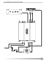
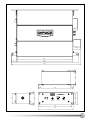
2. CONNECTIONS & CONTROLS
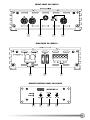
2.1 FRONT PANEL CONNECTIONS
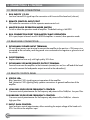
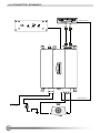
1RCA INPUTS 1/2-CH
Low-level stereo RCA signal input for connection with line-out of the head-unit (sub-out)
2REMOTE CONTROL INPUT PORT
DIN socket for connection with the separate remote control unit
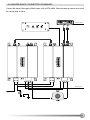
3 MASTER/SLAVE OPERATION MODE SWITCH
Switch to select the operation mode of amplifier. The default setting is MASTER
4RCA CONNECTION PORT FOR MASTER/SLAVE OPERATION
RCA input/output to branch two EA1500FLX amplifiers in master/slave operation mode
2.2 REAR PANEL CONNECTIONS
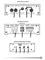
5DETACHABLE POWER INPUT TERMINAL
25 mm² direct power input terminal to connect the amplifier to the positive +12V power wire
connected to the car battery and the ground wire connected to the negative or ground wire of
the vehicle
6 FUSE TERMINAL
Replace defective fuses only with high quality 30 A fuses
7DETACHABLE SPEAKER/REMOTE OUTPUT TERMINAL
Terminal to connect the amplifier to the Automatic (remote) turn-on/turn-off lead of the head
unit and to connect the loudspeaker output terminal to the subwoofer(s)
2.3 REMOTE CONTROL PANEL
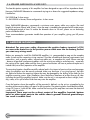
8STATUS LEDs
Blue “operation” LED signaling correct operation of the amplifier
Red “protection” LED signaling faulty speaker connections or general malfunction of the
amplfier
9LOW PASS CROSSOVER FREQUENCY CONTROL
Crossover control potentiometer for the frequency adjustment of the 24dB/oct. low-pass filter
10SUBSONIC CROSSOVER FREQUENCY CONTROL
Crossover control potentiometer for the frequency adjustment of the 24dB/oct. subsonic
high-pass filter
11INPUT GAIN CONTROL
Input level gain control potentiometer, allows matching the output voltage of the head-unit’s
RCA line-outs to the amplifier input
6