1
Wiring
Stand-Alone Applications
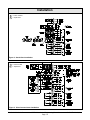
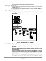
Connect the normally-open contacts of each waterflow switch (maximum of 5) or mechanically
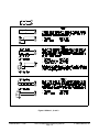
activated initiating device to the Alarm Initiating Circuit in parallel as shown in Figure 2.
Slave Communicator Applications
Connect the Alarm Initiating Circuit to an alarm indicator output (normally-open, dry closure)
on the FACP (see Figure 3). Connect terminals 6 and 7 to the common contact, and terminals
8 and 9 to the normally-open contact. Program Retard Time and Reset Time for 0 seconds
when connecting the Alarm Initiating Circuit to an existing FACP.
74-06200-000-C 12/98
D2071A Installation/Programming Manual
Page 13
© 1998 Radionics, Inc.