1
Table of Contents
Section
Page
The D2071A Fire Control/Communicator
4
Introduction
4
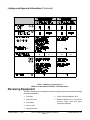
Listings and Approval Information
5
D2071A Control/Communicator Assembly
8
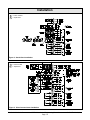
Installation
Before You Begin
Terminal Block
3
9
10
Step 1: Earth Ground
11
Step 2: Zone 1, Alarm Initiating Circuit
11
10 11 12
Step 3: Zones 2 and 3, Supervisory Circuits
14
16 17 18
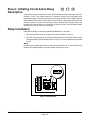
Step 4: Initiating Circuit Alarm Relay
16
13 14 15
Step 5: Phone Line Trouble Relay
17
1
2
Step 6: Primary Power Supply
17
4
5
Step 7: Secondary Power Supply and Charging Circuit
18
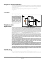
Step 8: Telephone Connections
20
Step 9: Cable Tie Installation
22
Step 10: D2071A Mounting
22
Step 11: End User Instruction Label
23
6
7
8
9
Programming
24
Receiver Reports
30
Trouble Shooting Guide
32
Specifications
36
Tables and Figures
Page
74-06200-000-C 12/98
Table 1: Mandatory Connections for NFPA 71 and NFPA 72 (Chap. 8)
7
Figure 1: D2071A Control/Communicator
8
Figure 2: Stand-Alone Installation
10
Figure 3: Slave Communicator Installation
10
Figure 4: Modes 1, 2, and 3
15
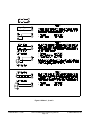
Figure 5: Relay Sockets
16
Figure 6: RJ31X Wiring
20
Figure 7: Insert the Cable Tie
22
Figure 8: Secure the Cable Tie and Wires
22
D2071A Installation/Programming Manual
Page 3
© 1998 Radionics, Inc.