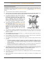
1
Owner’s Guide and Installation Instructions Solar Loline Storage Tank WARNING: Plumber – Be Aware Use copper pipe ONLY. Plastic pipe MUST NOT be used. It is a requirement of a solar water heater installation that all pipe work be in copper and not plastic, due to the effects of high water temperatures and pressures. This water heater must be installed and serviced by a qualified person. Please leave this guide with the householder. WARNING: Plumber – Be Aware The solar hot and solar cold pipes between the solar storage tank and the solar collectors MUST BE of copper. All compression fittings must use brass or copper olives. The full length of the solar hot and solar cold pipes MUST BE insulated. The insulation must: be of a closed cell type or equivalent, suitable for a solar water heating application and capable of withstanding the temperature of the water generated by the solar collectors under stagnation conditions The specification of the chosen insulation material should be checked with the insulation manufacturer prior to installation as different materials may vary in temperature tolerance. be at least 13 mm thick, however thicker insulation may be required to comply with the requirements of AS/NZS 3500.4 be weatherproof and UV resistant if exposed extend through any penetrations in the eaves, ceiling and roof cover valves and fittings in the solar hot and solar cold pipe work be fitted up to and cover the connections on both the solar storage tank and the solar collectors. Note: Failure to observe these requirements increases the risk of freeze damage. Uninsulated pipe work, including concealed in cavities and roof spaces or where it may be in contact with a metal roof, may lead to freeze damage. The system has NO WARRANTY for freeze damage if the solar hot and solar cold pipes are not insulated in accordance with the installation instructions. The insulation is essential to assist in providing freeze protection, will offer corrosion protection to a metal roof against water runoff over the copper pipe, assist in avoiding accidental contact with the solar pipe work as high temperature water can flow from the solar collectors to the solar storage tank and also reduce pipe heat losses. The insulated copper pipe work: should be fixed at suitable locations to prevent or reduce the possibility of noise from water hammer and vibration from occurring is not to be placed or installed in contact with plastic pipe work. Likewise, plastic pipe work is not to be placed or installed in contact with the insulated copper pipe work after the solar circuit is installed. Plastic pipe MUST NOT be used, as it will not withstand the temperature and pressure of the water generated by the solar collectors under stagnation conditions. The solar collectors can generate extremely high water temperatures up to 150°C and high water pressure of 1000 kPa. Plastic pipe cannot withstand these temperatures and pressures and MUST NOT be used. Failure of plastic pipe can lead to the release of high temperature water and cause severe water damage and flooding. The highest point of the solar cold pipe and solar hot pipe must be where they connect to the solar collectors, to avoid the possibility of air locks occurring in the system. There must be a continuous fall in the pipe work between the solar collectors and solar storage tank. Horizontal runs of pipe work are acceptable and may be installed. A non return valve MUST BE installed on the cold water line to the solar storage tank AFTER the cold water branch to a temperature limiting device. The pressure applied to the solar circuit and solar collectors during a pressure test of a direct open circuit system MUST NOT exceed 1000 kPa, otherwise damage may result to the solar collectors. Refer to “Pressure Testing” on page 34. PATENTS This water heater may be protected by one or more patents or registered designs. ® TRADE MARKS Registered trademark of Rheem Australia Pty Ltd. ™ Trademark of Rheem Australia Pty Ltd. Note: Every care has been taken to ensure accuracy in preparation of this publication. No liability can be accepted for any consequences, which may arise as a result of its application. CONTENTS HOUSEHOLDER – We recommend you read pages 4 to 19. The other pages are intended for the installer but may be of interest. About Your Water Heater ............................................................................................................ 4 Regular Care .............................................................................................................................. 11 Water Supplies........................................................................................................................... 14 Save A Service Call ................................................................................................................... 17 Installation – Solar Storage Tank............................................................................................. 20 Installation – Solar Collectors .................................................................................................. 31 Installation – Solar and Gas Booster Connections ................................................................ 35 Connections – Plumbing .......................................................................................................... 41 Connections – Electrical ........................................................................................................... 44 Commissioning .......................................................................................................................... 45 Draining The Solar Collectors .................................................................................................. 49 Draining The Water Heater ....................................................................................................... 49 Warranty ..................................................................................................................................... 51 3 ABOUT YOUR WATER HEATER WATER HEATER APPLICATION This water heater is designed for use in a single family domestic dwelling for the purpose of heating potable water. Its use in an application other than this may shorten its life. MODEL TYPE ® ® Your Rheem Loline 511 220 water heater is designed for the solar collectors to be roof mounted and the vitreous enamel lined solar storage tank to be installed at ground or floor level, remotely from the solar collectors. The solar storage tank is suitable for installation either outdoor or indoor and with one or two HBT 200 solar collectors. If an in-series gas booster is mounted to the solar storage tank, then it is suitable for outdoor installation only. The system is not suitable for installation above 400 metres altitude. The system has a level of freeze protection designed to guard the system against damage from freeze conditions (refer to “Freeze Protection” on page 7). The system must be installed with the full length of the solar hot and solar cold pipes insulated to offer protection against freeze damage (refer to “Pipe Work and Insulation” on page 6). Freeze conditions occur below 6°C. The system has NO WARRANTY for freeze damage when installed above 400 metres altitude or if the solar hot and solar cold pipes are not insulated in accordance with the installation instructions (refer to “Terms of the Rheem Warranty” on page 51). Note: The Rheem warranty against freeze damage applies only to systems installed in Australia. This solar water heater is designed to be installed with a Rheem continuous flow 874 020 or 874 027 model in-series gas booster mounted onto the storage tank or installed remotely. The solar water heater may be installed with another suitable type of remotely installed in-series continuous flow or storage booster. If the in-series water heater is other than a Rheem continuous flow 874 020 or 874 027 model inseries gas booster, then the references to the in-series gas booster in this guide may not be applicable to the installation. For information relating to the function and operation of the in-series water heater, refer to the Owner‟s Guide and Installation Instructions supplied with the water heater. SOLAR OPERATION The Rheem Loline open circuit system has its vitreous enamel lined solar storage tank installed at ground or floor level, remotely from the solar collectors. As the sun heats the water in the solar collectors the increase in temperature activates the circulator. The circulator then moves the water from the solar collectors through an insulated copper pipe to the solar storage tank. The circulator switches on whenever the water in the solar collectors is hotter than the water in the tank. Cooler water from the solar storage tank is circulated to the solar collectors to be heated by the sun‟s energy. This process continues while solar energy is available and until the water in the solar storage tank reaches a temperature of 70°C to 80°C. Automatic safety controls are fitted to the water heater to provide safe and efficient operation. 4 ABOUT YOUR WATER HEATER MAINS PRESSURE The water heater is designed to operate at mains pressure by connecting directly to the mains water supply. If the mains supply pressure in your area exceeds that shown on page 23, a pressure limiting valve must be fitted. The supply pressure should be greater than 350 kPa for true mains pressure operation to be achieved. A minimum water supply pressure of 200 kPa is required to enable the solar circulator and solar circuit system to operate effectively. HOW HOT SHOULD THE WATER BE? The solar control unit will circulate water through the solar collectors until a temperature of 70°C to 80°C is reached in the solar storage tank. During periods of low solar energy gain, the continuous flow inseries gas booster will boost the water temperature automatically to its preset outlet temperature setting, or to the temperature setting of another type of in-series booster water heater. The factory preset outlet temperature setting of the in-series gas booster is: 874 020 and 874 027 models typical maximum temperature from solar gain maximum recommended supply temperature to bathrooms and ensuites 60°C Note: The preset outlet temperature setting of a continuous flow inseries gas booster cannot be adjusted by the householder. The setting can only be adjusted by the installer, Rheem Service or their nearest Accredited Service Agent. Note: AS 3498 requires that a water heater provides the means to inhibit the growth of Legionella bacteria in potable water. If this water heater is installed with an in-series continuous flow gas booster, then this requirement of AS 3498 can be satisfied provided the booster is energised, its preset outlet temperature setting is 70°C or higher and a remote temperature controller is not used. If this water heater is installed with an in-series storage booster, then this requirement of AS 3498 can be satisfied provided the storage booster is energised and its thermostat setting is 60°C or higher. Warning: Temperature controllers must not be fitted to the in-series water heater as part of a solar water heater system because water at a temperature much higher than the controller setting can be delivered. HOTTER WATER INCREASES THE RISK OF SCALD INJURY This water heater can deliver water at temperatures which can cause scalding. Check the water temperature before use, such as when entering a shower or filling a bath or basin, to ensure it is suitable for the application and will not cause scald injury. We recommend and it may also be required by regulations that an approved temperature limiting device be fitted into the hot water pipe work to the bathroom and ensuite when this water heater is installed. This will keep the water temperature below 50°C at the bathroom and ensuite. The risk of scald injury will be reduced and still allow hotter water to the kitchen and laundry. WARNING This water heater is only intended to be operated by persons who have the experience or the knowledge and the capabilities to do so. This water heater is not intended to be operated by persons with reduced physical, sensory or mental capabilities i.e. the infirm, or by children. Children should be supervised to ensure they do not interfere with the water heater. This water heater uses 240 V AC electrical power for operation of the control systems and the electrically operated components. The removal of the front cover will expose 240 V wiring. It must only be removed by a qualified person. The power lead from the solar controller must be plugged into a weatherproof electrical outlet if installed outdoors. Take care not to touch the power plug with wet hands. Care should be taken not to touch the pipe work connecting the solar storage tank and the solar collectors. Very high temperature hot water can be generated by the solar collectors under certain conditions and flow through the pipe work from the solar collectors to the solar storage tank. 5 ABOUT YOUR WATER HEATER SAFETY This water heater is supplied with a thermostat, an over temperature energy cut-out, temperature sensors and a combination temperature pressure relief valve. These devices must not be tampered with or removed. The water heater must not be operated unless each of these devices is fitted and is in working order. The operation of the over-temperature cut-out on the thermostat indicates a possibly dangerous situation. If the over-temperature cut-out operates, it must not be reset and the water heater must be serviced by a qualified person. If the power supply cord or plug to the solar storage tank is damaged, it must be replaced by a qualified person in order to avoid a hazard. The power supply cord and plug must be replaced with a genuine replacement part available from Rheem. Phone Rheem Service or their nearest Accredited Service Agent to arrange for an inspection. Warning: For continued safety of this water heater it must be installed, operated and maintained in accordance with the Owner‟s Guide and Installation Instructions. The Rheem warranty can become void if relief valves or other safety devices are tampered with or if the installation is not in accordance with these instructions. PIPE WORK AND INSULATION The solar hot and solar cold pipe work between the solar storage tank and the solar collectors and between the solar storage tank and a remote in-series water heater (if one is installed) MUST BE of copper. The full length of the solar hot and solar cold pipes MUST BE insulated. The insulation must: be of a closed cell type or equivalent, suitable for a solar water heating application and capable of withstanding the temperature of the water generated by the solar collectors under stagnation conditions be at least 13 mm thick, however thicker insulation may be required to comply with the requirements of AS/NZS 3500.4 be weatherproof and UV resistant if exposed extend through any penetrations in the eaves, ceiling and roof cover valves and fittings in the solar hot and solar cold pipe work be fitted up to and cover the connections on both the solar storage tank and the solar collectors. Note: Failure of these requirements to be observed increases the risk of freeze damage. Uninsulated pipe work, including concealed in cavities and roof spaces or where it may be in contact with a metal roof, may lead to freeze damage. There is NO WARRANTY for freeze damage if the solar hot and solar cold pipes are not insulated in accordance with the installation instructions. The insulation is essential to assist in providing freeze protection, will offer corrosion protection to a metal roof against water runoff over the copper pipe, assist in avoiding accidental contact with the solar pipe work as high temperature water can flow from the solar collectors to the solar storage tank and also reduce pipe heat losses. Plastic pipe MUST NOT be used, as it will not withstand the temperature and pressure of the water generated by the solar collectors under certain conditions (refer to Warning on page 33). 6 ABOUT YOUR WATER HEATER FREEZE PROTECTION The system has a level of freeze protection designed to guard the system against damage from freeze conditions. The system must be installed with the full length of the solar hot and solar cold pipes insulated to offer protection against freeze damage (refer to “Pipe Work and Insulation” on page 6). Freeze conditions occur below 6°C. The system has NO WARRANTY for freeze damage when installed above 400 metres altitude or if the solar hot and solar cold pipes are not insulated in accordance with the installation instructions (refer to “Terms of the Rheem Warranty” on page 51). Note: The Rheem warranty against freeze damage applies only to systems installed in Australia. The anti freeze control is designed to recirculate a small amount of water from the solar storage tank through the solar pipe work and solar collectors during periods of low temperatures. This is to prevent the water inside the pipe work and collectors from freezing. Additional freeze protection is provided by the anti-freeze heating unit, which is for heating the water at the bottom of the solar storage tank at times of low cold water temperature. The anti-freeze heating unit provides additional energy to the water to assist in the prevention of freezing in the solar pipe work and solar collectors. The anti-freeze heating unit is controlled by the solar controller and will only be energised when the water temperature is low and the circulator activates in the frost mode. The water temperature is monitored by the cold sensor. If the water temperature at the bottom of the solar storage tank is less than 10°C when the circulator activates in the frost mode, the anti-freeze heating unit will be energised and will heat the water by a few degrees. The anti-freeze heating unit will be de-energised when either the frost mode is shut down or the water temperature is increased to 15°C. It is essential the electrical circuit to the solar storage tank is continually turned on if there is a risk of freezing. The Rheem warranty does not cover damage caused by freeze conditions when the electrical circuit to the solar storage tank is turned off or interrupted. An over temperature energy cut out is incorporated in a thermostat which is mounted on the solar storage tank behind the front cover. Notes: If it is necessary to switch the power off to the solar control unit and there is a risk of freezing, then it is necessary to have your plumber drain the solar collectors and solar flow and return pipe work. The freeze protection system will be rendered inoperable if electrical power is not available at the solar control unit. Damage caused by freezing due to no power at the solar control unit, is not covered by the Rheem warranty. The system is not covered for freeze damage above 400 metres altitude. Refer to “Terms of the Rheem Warranty” on page 51. 7 ABOUT YOUR WATER HEATER SOLAR MONITOR A solar monitor is located on the front of the top cover and houses both a green and a red LED. The green LED, marked “Solar”, indicates the current operational mode of the solar water heater and the red LED, marked “Attention”, indicates a fault mode. The green LED will emit either a constant glow or a series of flashes, with a 2 second interval between each series. The red LED will emit a series of flashes, with a 2 second interval between each series, only if there is a particular fault condition with the system. The operational modes are: Flashes solid green (remains on) green slow pulse green rapid pulse 3 x green no green (remains off) Operational Modes Standby mode Standby mode (power on for less than 48 hours) Circulating water through collectors Circulating water through collectors (power on for less than 48 hours) Power outage or call for service If the power supply to the solar control unit is on and the green LED is off or the red LED is flashing, this indicates there may be a fault with the water heater. The red LED may emit up to six flashes in each series of flashes. Notes: If the system is in standby mode with the green LED emitting either a constant glow or slow pulsing flashes (circulator is off) and the solar storage tank is full of hot water, the red LED may simultaneously emit a constant glow if solar radiation is still being received by the solar collectors. This does not indicate a fault. The red LED will go out when the temperature in the solar collectors decreases. During periods of high solar radiation and the circulator activates after having been off (the green LED will emit either a rapid pulse or a series of three flashes), it is possible the red LED may simultaneously emit a rapid pulse for a period of up to ten (10) minutes. This does not indicate a fault. If the red LED continues to emit a rapid pulse for longer than ten (10) minutes, or emits a series of flashes, then count the number of flashes and phone Rheem Service or their nearest Accredited Service Agent to arrange for an inspection. PRECAUTIONS Where damage to property can occur in the event of the water heater leaking, the water heater must be installed in a safe tray. Construction, installation and draining of a safe tray must comply with AS/NZS 3500.4 and all local codes and regulatory authority requirements. The water heater must be maintained in accordance with the Owner‟s Guide and Installation Instructions. Refer to “Regular Care” on page 11 and to “Anode Inspection and Replacement” on page 15. If this water heater is to be used where an uninterrupted hot water supply is necessary for your application or business you should ensure that you have back up redundancy within the hot water system design. This should ensure the continuity of hot water supply in the event that this water heater were to become inoperable for any reason. We recommend you seek advice from your plumber or specifier about your needs and building back up redundancy into your hot water supply system. 8 ABOUT YOUR WATER HEATER BLEEDING THE SOLAR COLLECTORS It is necessary to purge air from the collector circuit: When the water heater is to be turned on and the solar collectors and solar hot and solar cold pipes have been drained. After maintenance has been conducted on the pipe work and air has entered the system. If the circulator appears not to be circulating water around the system. Warning: Bleeding the solar collectors should be conducted in the morning, within three hours of sunrise, when the water temperature inside the solar collectors is lower. To purge air from the collector circuit: Ensure the water heater is full of water and all of the hot taps are turned off. Using a flat blade screwdriver, open the bleed valve (if it is not already open) fitted above the solar hot water (from collector) inlet of the solar storage tank (see diagram). The mains pressure will force water to flow from the tank and through the pipe work and solar collectors, expelling air from the collector circuit through the bleed valve. This is evidenced by spurting of water from the drain line connected to the bleed valve. Warning: Exercise care to avoid any splashing of water, as water discharged from the solar collectors may be of a very high temperature. Close the bleed valve when water runs freely from the drain line. Air Bleed Valve & Non-Return Valve Assembly Assembly including connection fittings Solar Pumped Open Circuit - Top Solar Connections TO TURN OFF THE WATER HEATER If you plan to be away from home for a few nights, we suggest you leave the water heater switched on. If it is necessary to turn off the water heater: Switch off the electrical supply at the power outlet to the solar storage tank (refer to note below). Close the cold water isolation valve at the inlet to the water heater. Refer to the Owner‟s Guide and Installation Instructions supplied with the in-series water heater for the procedure to turn off the in-series water heater. Note: If there is a risk of freezing conditions, the electrical supply to the solar storage tank should not be switched off unless the solar collectors are drained, otherwise damage could result (refer to “Freeze Protection” on page 7). 9 ABOUT YOUR WATER HEATER TO TURN ON THE WATER HEATER Open the cold water isolation valve fully at the inlet to the water heater. If the solar collectors and solar hot and solar cold pipes have been drained, it will be necessary to bleed the collector circuit (refer to “Bleeding the Solar Collectors” on page 9). If the electrical supply to the water heater has been switched off: Switch on the electrical supply at the power outlet to the solar storage tank. The power outlet must be switched on for the solar control system to operate and solar gain to be achieved and for the anti-freeze heating unit to operate and offer additional freeze protection. HOW DO I KNOW IF THE WATER HEATER IS INSTALLED CORRECTLY? Installation requirements are shown on pages 20 and 30. The water heater must be installed: by a qualified person, and in accordance with the installation instructions, and in compliance with Standards AS/NZS 3500.4, AS/NZS 3000 and all local codes and regulatory authority requirements. In New Zealand, the installation must also conform with Clause G12 of the New Zealand Building Code. Warning: Temperature controllers must not be fitted to the in-series water heater as part of a solar water heater system because water at a temperature much higher than the controller setting can be delivered. Refer also to “Pipe Work and Insulation” on page 6. VICTORIAN CUSTOMERS Notice to Victorian Customers from the Victorian Plumbing Industry Commission. This water heater must be installed by a licensed person as required by the Victorian Building Act 1993. Only a licensed person will give you a Compliance Certificate, showing that the work complies with all the relevant Standards. Only a licensed person will have insurance protecting their workmanship for 6 years. Make sure you use a licensed person to install this water heater and ask for your Compliance Certificate. DOES THE WATER CHEMISTRY AFFECT THE WATER HEATER? The water heater is suitable for most public water supplies, however some water chemistries may have detrimental effects on the water heater, its components and fittings. Refer to “Water Supplies” on page 14. If you are in a known harsh water area or you are not sure of your water chemistry, have your water checked against the conditions described on pages 14 to 16. HOW LONG WILL THE WATER HEATER LAST? The water heater is supported by a manufacturer‟s warranty (refer to page 51). There are a number of factors that will affect the length of service the water heater will provide. These include but are not limited to the water chemistry, the water pressure, the water temperature (inlet and outlet) and the water usage pattern. Refer to “Precautions” on page 8. GOING ON HOLIDAYS It is not necessary to switch off the electrical supply at the power outlet to the solar control unit. Refer to “To Turn Off The Water Heater” on page 9. Also if the system is not used for a period in excess of 2 weeks it is recommended the solar collectors be covered. 10 REGULAR CARE MINOR SIX MONTH MAINTENANCE It is recommended minor maintenance be performed every six months by the dwelling occupant. The minor maintenance includes: Operate the easing lever on the temperature pressure relief valve. It is very important you raise and lower the lever gently. Refer to “Temperature Pressure Relief Valve” on page 12. Warning: Exercise care to avoid any splashing of water, as water discharged from the drain line will be hot. Stand clear of the drain line‟s point of discharge when operating the valve‟s lever. Operate the easing lever on the expansion control valve (if fitted). It is very important you raise and lower the lever gently. Refer to “Expansion Control Valve” on page 12. Check the drain line from the safe tray (if one is installed) is not blocked. ANNUAL SERVICE If this water heater is installed with an integrated or remotely installed in-series gas booster, then for safe and efficient operation, it is recommended an annual service be conducted on the gas booster. Refer to the Owner‟s Guide and Installation Instructions supplied with the gas booster. MAJOR FIVE YEAR SERVICE It is recommended a major five year service be conducted on the water heater. Warning: Servicing of a water heater must only be carried out by qualified personnel. Phone Rheem Service or their nearest Accredited Service Agent. Note: The five year service and routine replacement of any components, such as the anode and relief valves, are not included in the Rheem warranty. A charge will be made for this work. Only genuine replacement parts should be used on this water heater. The major service includes the following actions: Replace the temperature pressure relief valve. Inspect and flush the expansion control valve (if fitted). If required, replace the valve. Inspect and if required, replace the anode. If the anode is not replaced, it should be replaced within three years of this service (refer to “Anode Inspection and Replacement” on page 15). Check the electric heating unit for excessive calcium build up or corrosion and replace if necessary. Check the solar control unit for correct operation. Flush and bleed the solar collectors. Clean the collector glass. Visually check the unit for any potential problems. Inspect all connections. Check the drain line from the safe tray (if one is installed) is not blocked. Note: The solar storage tank may need to be drained during this service. After the completion of the service, the solar storage tank will take some time to reheat the water by solar gain. 11 REGULAR CARE TEMPERATURE PRESSURE RELIEF VALVE This valve is near the top of the water heater and is essential for its safe operation. It is possible for the valve to release a little water through the drain line during each heating period. This occurs as the water is heated and expands by approximately 1/50 of its volume. Continuous leakage of water from the valve and its drain line may indicate a problem with the water heater (refer to “Temperature Pressure Relief Valve Running” on page 18). Warning: Never block the outlet of this valve or its drain line for any reason. Operate the easing lever on the temperature pressure relief valve once every six months. It is very important you raise and lower the lever gently. DANGER: Failure to do this may result in the water heater cylinder failing, or under certain circumstances, exploding. Warning: Exercise care to avoid any splashing of water, as water discharged from the drain line will be hot. Stand clear of the drain line‟s point of discharge when operating the valve‟s lever. If water does not flow freely from the drain line when the lever is lifted, then the water heater must be checked. Phone Rheem Service or their nearest Accredited Service Agent to arrange for an inspection. The temperature pressure relief valve should be replaced at intervals not exceeding 5 years, or more frequently in areas where there is a high incidence of water deposits (refer to “Water Supplies” on page 14). EXPANSION CONTROL VALVE In many areas, including South Australia, Western Australia and scaling water areas, an expansion control valve is fitted to the cold water line to the water heater. The expansion control valve may discharge a small quantity of water from its drain line during the heating period instead of the temperature pressure relief valve on the water heater. Operate the easing lever on the expansion control valve once every six months. It is very important you raise and lower the lever gently. The expansion control valve should be checked for performance or replaced at intervals not exceeding 5 years, or more frequently in areas where there is a high incidence of water deposits. water heater lift until water flows from the drain line – lower gently drain line COLLECTOR GLASS Ensure the glass on your solar collectors is free of dust, salt spray or any other matter, which may reduce the effectiveness of the solar collectors. If the collector glass becomes dirty, hose down or if the solar collectors are accessible, wash the collector glass with water and a soft brush when the solar collectors are cool. Have any trees trimmed which may shade the solar collectors. Rheem solar collectors have passed the AS/NZS 2712 requirements for resistance to hailstone damage, so it is not normally necessary to fit a guard to a collector. Stone Guards are available to provide a level of protection to the collectors against vandalism or accidental damage. Refer to your local Solar Distributor for details. 12 REGULAR CARE FLUSHING THE SOLAR COLLECTORS It may be necessary to flush the solar collectors if there is sediment in the water supply. This should be conducted in the morning, within three hours of sunrise, when the water temperature inside the solar collectors is lower. Open a hot water tap and allow the water to run for five (5) minutes prior to flushing the solar collectors. Close the hot tap. Wait a further five (5) minutes before attempting to flush the solar collectors. This will assist in the transfer of any high temperature water in the solar collectors to the solar storage tank. Warning: Exercise care, as water discharged from the solar collectors may be of a very high temperature. To flush the solar collectors, follow the procedure “Bleeding the Solar Collectors” on page 9, allowing the water to flow from the bleed valve drain line for five minutes before closing the bleed valve. It is recommended to flush the solar collectors every five years. This will assist in keeping the solar collectors, solar cold pipe and solar hot pipe clear of sediment (refer to “Major Five Year Service” on page 11). 13 WATER SUPPLIES This water heater must be installed in accordance with this advice to be covered by the Rheem warranty. This water heater is manufactured to suit the water conditions of most public reticulated water supplies. However, there are some known water chemistries which can have detrimental effects on the water heater and its operation and / or life expectancy. If you are unsure of your water chemistry, you may be able to obtain information from your local water supply authority. This water heater should only be connected to a water supply which complies with these guidelines for the Rheem warranty to apply. CHANGE OF WATER SUPPLY The changing or alternating from one water supply to another can have a detrimental effect on the operation and / or life expectation of a water heater cylinder, a temperature pressure relief valve, a heating unit and a solar collector in a direct solar water heater system. Where there is a changeover from one water supply to another, e.g. a rainwater tank supply, bore water supply, desalinated water supply, public reticulated water supply or water brought in from another supply, then water chemistry information should be sought from the supplier or it should be tested to ensure the water supply meets the requirements given in these guidelines for the Rheem warranty to apply. ANODE The vitreous enamel lined cylinder of the water heater is only covered by the Rheem warranty when the total dissolved solids (TDS) content in the water is less than 2500 mg/L and when the correct colour coded anode is used. If an incorrect colour coded anode is used in the water heater, any resultant faults will not be covered by the Rheem warranty. In addition, the use of an incorrect colour coded anode may shorten the life of the water heater cylinder. The correct colour coded anode must be selected and fitted to the water heater in accordance with the following advice and the Anode Selection chart on page 14 for the Rheem warranty to apply to the water heater cylinder. Total Dissolved Solids Anode colour code 0 – 40 mg/L Green 40 – 150 mg/L Green or Black 150 – 400 mg/L Black 400 – 600 mg/L Black or Blue 600 – 2500 mg/L Blue 2500 mg/L + Blue (no cylinder warranty) The changing of anodes must be carried out by a qualified person. Note: Some water analysis reports may state the conductivity of the water rather than the level of total dissolved solids. Conductivity, measured in microsiemens per centimetre (µS / cm), is directly proportional to the TDS content of the water. TDS, in mg / L, is approximately 70% of the conductivity in µS / cm. TOTAL DISSOLVED SOLIDS & CONDUCTIVITY (vitreous enamel lined water heater cylinder) no warranty applies warranty applies to a vitreous enamel lined water heater cylinder if the correct coloured anode is used for the TDS / conductivity level of water 0 40 Green 0 60 150 400 600 TOTAL DISSOLVED SOLIDS (TDS) - mg/L Black 215 570 2500 Blue 860 CONDUCTIVITY - µS/cm ANODE SELECTION 14 to a vitreous enamel lined water heater cylinder Blue 3570 WATER SUPPLIES ANODE INSPECTION AND REPLACEMENT The anode installed in a vitreous enamel lined steel water heater cylinder will slowly dissipate whilst protecting the cylinder. The life of the cylinder may be extended by replacing the anode. If the anode is not replaced during a five year service (refer to “Major Five Year Service” on page 11) then the maximum time after installation when the anode should be replaced is 8 years. For water supplies which are either softened, desalinated or where the water supply may alternate between a water tank and a reticulated public supply or another supply, it is recommended the anode be replaced within 5 years of installation. CAUTION If the water supply has a TDS greater than 150 mg/L and a green anode has not been changed to a black anode, or if the TDS is greater than 600 mg/L and the anode has not been changed to a blue anode, there is the possibility the anode may become overactive and hydrogen gas could accumulate in the top of the water heater during long periods of no use. If, under these conditions, the water heater has not been used for two or more weeks the following procedure should be carried out before using any electrical appliances (automatic washing machines and dishwashers) which are connected to the hot water supply. The hydrogen, which is highly flammable, should be vented safely by opening a hot tap and allowing the water to flow. There should be no smoking or naked flame near the tap whilst it is turned on. Any hydrogen gas will be dissipated. This is indicated by an unusual spurting of the water from the tap. Once the water runs freely, any hydrogen in the system will have been released. SATURATION INDEX The saturation index is used as a measure of the water‟s corrosive or scaling properties. In a corrosive water supply, the water can attack copper parts and cause them to fail. Where the saturation index is less than –1.0, the water is very corrosive and the Rheem warranty does not apply to a copper sheathed heating unit or to a solar collector in a direct solar water heater system. A corrosion resistant heating unit must be used for the Rheem warranty to apply to the heating unit. In a scaling water supply calcium carbonate is deposited out of the water onto any hot metallic surface. Where the saturation index exceeds +0.40, the water is very scaling. An expansion control valve must be fitted on the cold water line after the non-return valve to protect and for the Rheem warranty to apply to the temperature pressure relief valve and water heater cylinder. Solar collectors in a direct solar water heater system should be covered when the water heater is not intended to be used for more than two weeks. Where the saturation index exceeds +0.80, the Rheem warranty does not apply to a standard watts density heating unit or to a solar collector in a direct solar water heater system. A low watts density heating unit must be used for the Rheem warranty to apply to the heating unit. Water which is scaling may be treated with a water softening device to reduce the saturation index of the water. Refer to the Saturation Index chart on page 16. Contact Rheem Service or their nearest Accredited Service Agent if a replacement heating unit is required. Refer to the cold water connection detail on page 41 for the position of the expansion control valve. 15 WATER SUPPLIES WITHIN WARRANTY SPECIFICATION -1.0 very corrosive 0 +0.4 no warranty applies to a: -standard watts density heating unit -direct (open circuit) solar collector no warranty applies to a: temperature pressure relief valve or a water heater cylinder unless an expansion control valve is fitted. no warranty applies to a: -copper sheathed heating unit -direct (open circuit) solar collector SATURATION INDEX (SI) SOLAR WATER HEATERS WITH ELECTRIC HEATING UNIT +0.8 SATURATION INDEX (calculated @ 80°C water temperature) scaling very scaling corrosive SUMMARY OF WATER CHEMISTRY ADVICE AFFECTING WARRANTY The water heater and its components are not suitable for certain water chemistries. Those chemistries are listed below. If the water heater is connected at any time to a water supply with the following water chemistry, the Rheem warranty will not cover any resultant faults on the components listed below: Water Chemistry Component Total Dissolved Solids (TDS) > 2500 mg/L water heater cylinder Total Dissolved Solids (TDS) not suitable for anode type water heater cylinder Saturation Index (SI) < -1.0 solar collector copper sheathed heating unit Saturation Index (SI) > +0.4 (if an expansion control valve is not fitted) water heater cylinder temperature pressure relief valve Saturation Index (SI) > +0.8 solar collector standard watts density heating unit 16 SAVE A SERVICE CALL Check the items below before making a service call. You will be charged for attending to any condition or fault that is not related to manufacture or failure of a part. NOT ENOUGH HOT WATER (OR NO HOT WATER) Insufficient sunlight Insufficient sunlight due to cloudy weather during hotter months or low solar energy contribution in colder months may mean the in-series water heater operates more often. Solar Control Unit Check the power supply cord is plugged in and the power outlet switched on. Is power available in the house? Try using another electrical appliance. Green LED is off or red LED is flashing on Solar Monitor If the green LED is off or the red LED is flashing on the Solar Monitor label, there may be a problem with the solar water heater operation and solar gain is not being achieved. This will result in the in-series gas booster operating to provide all of the hot water required. Refer to the notes under “Solar Monitor” on page 8. Switch off the electrical supply at the power outlet to the solar control unit for a few seconds, then switch on again. If the green LED remains off or the red LED recommences to flash, then count the number of flashes and phone Rheem Service or their nearest Accredited Service Agent to arrange for an inspection. Collectors shaded If trees or other objects shade the solar collectors or if the glass is dirty, the effectiveness of the solar collectors will be greatly reduced. Have the trees trimmed or the solar collectors relocated if the obstruction is permanent or clean the collector glass (refer to “Collector Glass” on page 12). Collector area is too small For most installations, the number of solar collectors recommended in Rheem literature has been proven to provide the required solar energy to meet the average family needs. However, in some circumstances if only one solar collector has been installed, it may be necessary to install a second solar collector. Air in collectors (no solar gain) It is possible under certain conditions, such as when the pipe work has been opened, that air may become trapped in the solar collectors. This will prevent the circulator from moving water around the collector circuit. The air will need to be purged from the solar collectors (refer to “Bleeding The Solar Collectors” on page 9). Are you using more hot water than you think? Is one outlet (especially the shower) using more hot water than you think? Very often it is not realised the amount of hot water used, particularly when showering. Carefully review the family‟s hot water usage. As you have installed an energy saving appliance, energy saving should also be practised in the home. Adjust your water usage pattern to take advantage of maximum solar gains. Have your plumber install a flow control valve to each shower outlet to reduce water usage. Temperature pressure relief valve running Is the relief valve discharging too much water? Refer to “Temperature Pressure Relief Valve Running” on page 18. 17 SAVE A SERVICE CALL TEMPERATURE PRESSURE RELIEF VALVE RUNNING Normal Operation It is normal and desirable this valve allows a small quantity of water to escape during the heating cycle. However, if it discharges more than a bucket full of water in 24 hours, there may be another problem. Continuous dribble Try gently raising the easing lever on the relief valve for a few seconds (refer to “Temperature Pressure Relief Valve” on page 12). This may dislodge a small particle of foreign matter and clear the fault. Release the lever gently. Steady flows for long period (often at night) This may indicate the mains water pressure sometimes rises above the designed pressure of the water heater. Ask your installing plumber to fit a pressure limiting valve. Warning: Never replace the relief valve with one of a higher pressure rating. Heavy flows of hot water until the water heater is cold - then stops until water reheats The water heater must be switched off at the isolating switch or switchboard. Phone Rheem Service or their nearest Accredited Service Agent to arrange for an inspection. EXPANSION CONTROL VALVE RUNNING If an expansion control valve is fitted in the cold water line to the water heater (refer to page 41) it may discharge a small quantity of water instead of the temperature pressure relief valve on the water heater. The benefit is that energy is conserved as the discharged water is cooler. IN-SERIES WATER HEATER OPERATING TOO FREQUENTLY You may find that the in-series water heater operates more frequently than expected. This will occur when the solar heated water temperature is lower than the temperature setting of the in-series water heater. This may be experienced during periods of low solar energy gain or if there has been heavy hot water usage. COLLECTOR GLASS The Rheem warranty DOES NOT cover breakage of solar collector glass. Check your household insurance policy covers collector glass breakage. Warning: No attempt should be made to remove or replace broken collector glass. The collector glass is not offered as a replacement part. Should the solar collector require replacement, contact Rheem Service or their nearest Accredited Service Agent. NOISE FROM THE SOLAR COLLECTORS This water heater is installed with higher performing selective surface solar collectors. When the solar storage tank is full of hot water, the circulator will turn off. The water in the solar collectors will continue to gain heat and increase in pressure when solar radiation is still available. When a hot tap is opened, this pressure is released and the high temperature water may turn to steam creating a sudden and loud rumbling noise and even a rattling or banging noise of the collectors against the roof cladding material. This results from the higher level of solar radiation and the water in the solar storage tank being at its maximum temperature and is not caused by a fault with the solar water heater. 18 SAVE A SERVICE CALL HIGHER THAN EXPECTED GAS BILLS With the installation of your new solar hot water system, maximum energy savings can be achieved with careful planning of hot water usage. Should you at any time feel your energy account is higher than expected, we suggest you check the following points: Is the relief valve running excessively? Refer to “Temperature Pressure Relief Valve Running” on page 18). Is one outlet (especially the shower) using more hot water than you think? Refer to “Not Enough Hot Water” on page 17. Is there a leaking hot water pipe, dripping hot water tap, etc? Even a small leak will waste a surprising quantity of hot water and energy. Replace faulty tap washers, and have your plumber rectify any leaking pipe work. Is the in-series water heater operating too frequently? Refer to “In-Series Water Heater Operating Too Frequently” on page 18. Has there been an increase in hot water usage? An increase in hot water usage may result in an increase in booster operation. Has your water heating tariff rate been increased by your energy retailer since your previous account? IF YOU HAVE CHECKED ALL THE FOREGOING AND STILL BELIEVE YOU NEED ASSISTANCE, PHONE RHEEM SERVICE OR THEIR NEAREST ACCREDITED SERVICE AGENT. 19 INSTALLATION – SOLAR STORAGE TANK THIS WATER HEATER IS FOR OUTDOOR INSTALLATION ONLY IF AN IN-SERIES GAS BOOSTER IS MOUNTED ON THE STORAGE TANK. THIS WATER HEATER IS NOT SUITABLE FOR POOL HEATING. The system is suitable for installation with one or two HBT 200 solar collectors. The system is not suitable for installation above 400 metres altitude. IMPORTANT NOTES Working on roofs is and should always be considered a hazardous activity, particularly early in the morning, late in the evening, when the roof is wet and during and after periods of rain. All work must be carried out in accordance with Local, State and Federal Occupational Safety, Health and Welfare Regulations. In particular, the requirements for safety whilst manual lifting, working at heights and on roofs. Installers must be competently trained in: Height Hazard Assessment Working at Height Procedures Assessment / Use / Wearing of correct height safety equipment (harnesses etc.) All other relevant safety factors specific to the installation and maintenance work to be compliant with suitable Occupational, Health and Safety Regulations / Codes. All relevant permits shall be obtained from the regulatory authorities before commencing work to install the solar hot water system. All work carried out must be performed by appropriately qualified tradespeople or be suitably supervised for trades assistant duties. Every care must be taken to protect and warn occupants of the building and the public from personal injury which may occur from falling tools, roof materials, fittings or any other hazards of a general nature. Advise the occupants of any inconvenience which may occur due to disconnection of existing water and electrical supplies. The connection, attachment, integration or general association of other equipment or parts which either directly or indirectly affect the operation or performance of this equipment could void the Rheem warranty. All packaging materials must be removed from the solar storage tank prior to its installation. This includes the removal of the cardboard base of the carton from the underside of the solar storage tank. FREEZE PROTECTION The system has a level of freeze protection designed to guard the system against damage from freeze conditions. The system must be installed with the full length of the solar hot and solar cold pipes insulated to offer protection against freeze damage (refer to “Warning: Plumber Be Aware” on page 33). Freeze conditions occur below 6°C. The system has NO WARRANTY for freeze damage when installed above 400 metres altitude or if the solar hot and solar cold pipes are not insulated in accordance with the installation instructions (refer to “Terms of the Rheem Warranty” on page 51). Note: The Rheem warranty against freeze damage applies only to systems installed in Australia. 20 INSTALLATION – SOLAR STORAGE TANK INSTALLATION STANDARDS The water heater must be installed: by a qualified person, and in accordance with the installation instructions, and in compliance with Standards AS/NZS 3500.4, AS/NZS 3000 and all local codes and regulatory authority requirements. In New Zealand, the installation must also conform with Clause G12 of the New Zealand Building Code. Victorian Installers Notice to Victorian Installers from the Victorian Plumbing Industry Commission if this solar water heater is installed in a new Class 1 dwelling in the State of Victoria. The system model number is to be recorded on the Certificate of Compliance. It is also a requirement to provide the householder with permanent documentation listing the system model number exactly as it is listed on the „Approved List‟ of approved solar water heaters. This documentation may be in the form of an indelible label adhered to the solar storage tank, or other suitable form placed in an accessible location, such as the meter box, for later inspection. WATER HEATER APPLICATION This water heater is designed for use in a single family domestic dwelling for the purpose of heating potable water. Its use in an application other than this may shorten its life. If this water heater is to be used where an uninterrupted hot water supply is necessary for the application or business, then there should be redundancy within the hot water system design. This should ensure the continuity of hot water supply in the event that this water heater was to become inoperable for any reason. We recommend you provide advice to the system owner about their needs and building backup redundancy into the hot water supply system. This solar water heater is designed to be installed with a Rheem continuous flow 874 020 or 874 027 model in-series gas booster mounted onto the storage tank or installed remotely. The solar water heater may be installed with another suitable type of remotely installed in-series continuous flow or storage booster. If the in-series water heater is other than a Rheem continuous flow 874 020 or 874 027 model in-series gas booster, then the references to the in-series gas booster in this guide may not be applicable to the installation. For information relating to the function and operation of the in-series water heater, refer to the Owner‟s Guide and Installation Instructions supplied with the water heater. Note: AS 3498 requires that a water heater provides the means to inhibit the growth of Legionella bacteria in potable water. If this water heater is installed with an in-series continuous flow gas booster, then this requirement of AS 3498 can be satisfied provided the booster is energised, its preset outlet temperature setting is 70°C or higher and a remote temperature controller is not used. If this water heater is installed with an in-series storage booster, then this requirement of AS 3498 can be satisfied provided the storage booster is energised and its thermostat setting is 60°C or higher. SOLAR WATER HEATER STORAGE TANK LOCATION The solar storage tank is suitable for either outdoor or indoor installation. If an in-series gas booster is mounted to the solar storage tank, then the installation must be outdoors. Whether located outdoor or indoor, the solar storage tank should be installed close to the most frequently used outlet and its position chosen with safety and service in mind. Consideration must also be given to the position of the solar storage tank in relation to the solar collectors. There are limitations on the maximum length of the solar hot and solar cold pipes between the solar storage tank and the solar collectors. Refer to “Solar Collector Location” on page 31 and to “Pipe Lengths” on page 32. 21 INSTALLATION – SOLAR STORAGE TANK Clearance must be allowed for servicing of the solar storage tank. The solar storage tank must be accessible without the use of a ladder or scaffold. Make sure the temperature pressure relief valve lever is accessible and the front cover, thermostat and booster heating unit can be removed for service. You must be able to read the information on the rating plate. If possible leave headroom of one water heater height so the anode can be inspected or replaced. Remember you may have to remove the entire solar storage tank later for servicing. It is recommended the solar storage tank be installed at ground or floor level and must stand vertically upright. The base of the water heater is made of corrosion resistant material, and it may be placed directly in contact with the supporting surface. It is not necessary to allow for free air circulation under the base of the water heater. Note: The water heater should not be placed in direct contact with a concrete surface that is less than two months old and not fully cured as this may attack the metal coating of the water heater base. A moisture barrier should be used between the two surfaces in this instance. Remember all local authorities have regulations about putting water heaters into roof spaces. The in-series gas booster must not be installed in an area with a corrosive atmosphere where chemicals are stored or where aerosol propellants are released. Remember the air may be safe to breathe, but when it goes through a flame, chemical changes take place which may attack the water heater. A secondary flue is not required. The water heater must not be installed indoors or in a confined space. The in-series gas booster must be located to ensure that the location of the flue terminal complies with the requirements of AS 5601 or AS/NZS 5601.1, as applicable under local regulations. As a guide the following requirements are extracted from the Gas Installations Standard. The distances are measured along the wall behind the water heater unless otherwise stated. At least 300 mm between the top of the flue terminal and the eaves. At least 300 mm (20L) or 500 mm (27L) between the flue terminal and the edge of any opening into the building, such as an openable door or window, measured horizontally and at right angles to the flue terminal. At least 1500 mm between the top of the flue terminal and the edge of any opening into the building, such as an openable door or window, measured vertically. At least 440 mm between the flue terminal and a return wall, measured horizontally. At least 300 mm between the flue terminal and an external corner, measured horizontally*. At least 1500 mm between the flue terminal and any opening into a building, in the direction of the flue discharge. At least 500 mm between the flue terminal and a fence, wall or other obstruction, in the direction of the flue discharge. Note: * If these horizontal distances cannot be achieved, AS/NZS 5601.1 states an equivalent horizontal distance measured diagonally from the nearest discharge point of the flue terminal to the wall or corner may be deemed to comply. Check with the local regulator. 22 INSTALLATION – SOLAR STORAGE TANK SAFE TRAY Where damage to property can occur in the event of the water heater leaking, the water heater must be installed in a safe tray. Construction, installation and draining of a safe tray must comply with AS/NZS 3500.4 and all local codes and regulatory authority requirements. AS/NZS 3500.4 also has particular requirements when a safe tray must be installed. MAINS WATER SUPPLY Where the mains water supply pressure exceeds that shown in the table below, an approved pressure limiting valve is required and should be fitted as shown in the installation diagram (refer to diagram on page 41). Model 220 Relief valve setting 1000 kPa Expansion control valve setting * 850 kPa Max. mains supply pressure With expansion control valve 680 kPa Without expansion control valve 800 kPa Min. mains supply pressure 200 kPa * Expansion control valve not supplied with the water heater. TANK WATER SUPPLY If the water heater is supplied with water from a tank supply and a minimum water supply pressure of 200 kPa at the water heater cannot be achieved, then a pressure pump system must be installed to allow the solar circuit system to operate. Care must be taken to avoid air locks. The cold water line from the supply tank should be adequately sized and fitted with a full flow gate valve or ball valve. Consideration must be given to any minimum water supply pressure requirements of an in-series water heater. HOT WATER DELIVERY This water heater can deliver water at temperatures which can cause scalding. It is necessary and we recommend that a temperature limiting device be fitted between the water heater and the hot water outlets in any ablution and public areas such as a bathroom, ensuite or public amenities, to reduce the risk of scalding. The installing plumber may have a legal obligation to ensure the installation of this water heater meets the delivery water temperature requirements of AS/NZS 3500.4 so that scalding water temperatures are not delivered to a bathroom, ensuite or other ablution or public area. The temperature limiting device used with a solar water heater should be capable of receiving a hot water supply temperature of up to 99°C and have a specified „minimum temperature differential‟ between the hot water inlet and the tempered water outlet of no greater than 10°C. In addition, the temperature limiting device used with a continuous flow water heater should have a specified „maximum permitted pressure variation‟ in either supply between the hot water inlet and the cold water inlet of no less than 15%. Refer to the specifications of the temperature limiting device. Warning: Temperature controllers must not be fitted to the in-series water heater as part of a solar water heater system because water at a temperature much higher than the controller setting can be delivered. Where a temperature limiting device is installed adjacent to the in-series water heater, the cold water line to the temperature limiting device can be branched off the cold water line either before or after the isolation valve and pressure limiting valve to the solar storage tank, but it MUST BE before the non return valve. If an expansion control valve is required, it must always be installed after the non return valve and be the last valve prior to the solar storage tank. Warning: A non return valve MUST BE installed on the cold water line to the solar storage tank AFTER the cold water branch to a temperature limiting device. 23 INSTALLATION – SOLAR STORAGE TANK If a combination isolation valve and non return valve (duo or trio valve) is installed on the cold water line to the solar water heater and the cold water line to the temperature limiting device branches off after this valve, then a second non return valve must be installed between the cold water branch and the solar storage tank. If a pressure limiting valve is installed on the cold water line to the solar water heater and the cold water line to a temperature limiting device branches off before this valve or from another cold water line in the premise, then a pressure limiting valve of an equal pressure setting may be required prior to the temperature limiting device. Integrated In-series Gas Booster as part of a Direct 511 220 Solar Water Heater Installation Two Temperature Zones Using a Temperature Limiting Device LEGEND Remote In-series Gas Booster as part of a Direct 511 220 Solar Water Heater Installation Two Temperature Zones Using a Temperature Limiting Device LEGEND 24 INSTALLATION – SOLAR STORAGE TANK CIRCULATED HOT WATER FLOW AND RETURN SYSTEM The solar storage tank of a solar water heater should not be installed as part of a circulated hot water flow and return system in a building. The benefits of solar gain will be significantly reduced and energy gained from the sun lost through the pipe work. If a circulated flow and return system is required, it is necessary to connect the return line after the solar storage tank and prior to the in-series water heater supplied from the solar water heater. If the in-series gas booster is mounted on the solar storage tank, then a suitable Tee must be installed at the inlet to the gas booster, after the flexible hose from the solar hot outlet on the tank. The circulated return line is to be connected to the Tee. A Rheem 874 model in-series gas booster can be installed as part of a circulated hot water flow and return system in a building. If the in-series water heater is a continuous flow water heater, its preset outlet temperature setting must be set to at least 60°C or to meet the requirement of AS 3498, its setting must be set to at least 70°C. If the in-series water heater is a storage water heater, its thermostat must always be set to at least 60°C. Notes: Water should not be circulated from a water heater with a temperature setting of less than 60°C. If the in-series booster is a continuous flow water heater, then the circulator must be: sized and set to provide a minimum flow rate of 3.0 L/min through the recirculated hot water flow and return system, and either thermostatically and / or timer controlled. The circulator must not be set to operate continuously, i.e. 24 hours per day. Temperature Limiting Device A temperature limiting device cannot be installed in circulated hot water flow and return pipe work. The tempered water from a temperature limiting device cannot be circulated. Where a circulated hot water flow and return system is required in a building, a temperature limiting device can only be installed on a dead leg, branching off the circulated hot water flow and return pipe. If circulated tempered water were to be returned back to the water heater, depending on the location of the return line connection on the water supply line to the water heater, then either: water will be supplied to the cold water inlet of the temperature limiting device at a temperature exceeding the maximum recommended water supply temperature, or when the hot taps are closed no water will be supplied to the cold water inlet of the temperature limiting device whilst hot water will continue to be supplied to the hot water inlet of the temperature limiting device. These conditions may result in either water at a temperature exceeding the requirements of AS/NZS 3500.4 being delivered to the hot water outlets in the ablution areas, or the device closing completely and not delivering water at all, or the device failing. Under either condition, the operation and performance of the device cannot be guaranteed. 25 INSTALLATION – SOLAR STORAGE TANK Integrated In-series Gas Booster as part of a Direct 511 220 Solar Water Heater Installation Circulated Hot Water Flow and Return System LEGEND Remote In-series Gas Booster as part of a Direct 511 220 Solar Water Heater Installation Circulated Hot Water Flow and Return System LEGEND REDUCING HEAT LOSSES The cold water line to and the hot water line from the water heater must be insulated in accordance with the requirements of AS/NZS 3500.4. The insulation must be weatherproof and UV resistant if exposed. The full length of the solar hot and solar cold pipes between the solar storage tank and the solar collectors MUST BE insulated. Refer to “Warning: Plumber Be Aware” on page 33. 26 INSTALLATION – SOLAR STORAGE TANK ANODE The vitreous enamel lined cylinder of the water heater is only covered by the Rheem warranty when the total dissolved solids (TDS) content in the water is less than 2500 mg/L and when the correct colour coded anode is used. If an incorrect colour coded anode is used in the water heater, any resultant faults will not be covered by the Rheem warranty. In addition, the use of an incorrect colour coded anode may shorten the life of the water heater cylinder. The correct colour coded anode for the water supply being used must be selected and fitted to the water heater for the Rheem warranty to apply to the water heater cylinder (refer to “Water Supplies” on page 14 and the Anode Selection chart on page 14). The black anode is typically fitted as standard. Total Dissolved Solids Anode colour code 0 – 40 mg/L Green 40 – 150 mg/L Green or Black 150 – 400 mg/L Black 400 – 600 mg/L Black or Blue 600 – 2500 mg/L Blue 2500 mg/L + Blue (no cylinder warranty) If the water supply has a TDS greater than 150 mg/L and a green anode has not been changed to a black anode, or if the TDS is greater than 600 mg/L and the anode has not been changed to a blue anode, there is the possibility the anode may become overactive and hydrogen gas could accumulate in the top of the water heater during long periods of no use. In areas where this is likely to occur, the installer should instruct the householder on how to dissipate the gas safely (refer to “Caution” on page 15). SADDLING - PIPE WORK To prevent damage to the cylinder when attaching pipe clips or saddles to the water heater jacket, we recommend the use of self-drilling screws with a maximum length of 13 mm. Should pre drilling be required, extreme caution must be observed when penetrating the jacket of the water heater. Note: If the cylinder is damaged as a result of attaching pipe clips or saddles to the jacket, any resultant faults will not be covered by the Rheem warranty. ANTI-FREEZE HEATING UNIT Additional freeze protection is provided by the anti-freeze heating unit, which is for heating the water at the bottom of the solar storage tank at times of low cold water temperature. The anti-freeze heating unit provides additional energy to the water to assist in the prevention of freezing in the solar pipe work and solar collectors. The anti-freeze heating unit is controlled by the solar controller and will only be energised when the water temperature is low and the circulator activates in the frost mode. The water temperature is monitored by the cold sensor. If the water temperature at the bottom of the solar storage tank is less than 10°C when the circulator activates in the frost mode, the anti-freeze heating unit will be energised and will heat the water by a few degrees. The anti-freeze heating unit will be de-energised when either the frost mode is shut down or the water temperature is increased to 15°C. The anti-freeze heating unit is supplied with power from the solar controller. The power outlet to the solar storage tank must be switched on for the anti-freeze heating unit to operate and offer additional freeze protection. 27 INSTALLATION – SOLAR STORAGE TANK DIMENSIONS AND TECHNICAL DATA Model Capacity 511 220 220 litres Tank Mass (kg) (without booster) Empty Full 77 297 Tank Mass (kg) (with booster) Empty Full 95 (20L) 315 (20L) 100 (27L) 320 (27L) Technical data is subject to change. storage tank only (remote boost) storage tank with 20L integrated gas booster storage tank with 27L integrated gas booster 28 INSTALLATION – SOLAR STORAGE TANK TYPICAL INSTALLATION (INTEGRATED BOOST) – OUTDOOR LOCATION HOT SENSOR CONNECTION SOLAR HOT PIPE Insulated copper pipe. Use a union connection at the bleed valve and non return valve assembly. Use a union connection at collector Nylon olives must NOT be used HOT SENSOR LEAD SOLAR COLD PIPE Insulated copper pipe. Use union connection at tank and collector. Nylon olives must NOT be used INSULATED FITTINGS BLEED VALVE DRAIN Drainline must terminate away from the base of the water heater. Discharge point must comply with local regulations CABLE TIE LEAD TO PIPE INSULATION RATING LABEL AT RIGHT (NOT SHOWN) TEMPERATURE PRESSURE RELIEF VALVE AT RIGHT (NOT SHOWN) SOLAR PREHEAT (HOT WATER) OUTLET RATING LABEL AND OPERATING INFORMATION TEMPERATURE PRESSURE RELIEF VALVE DRAIN LINE AT RIGHT (NOT SHOWN) Drainline must terminate away from the base of the water heater. Discharge point must comply with AS/NZS 3500.4 INSULATED SOLAR PREHEAT (HOT WATER) PIPE HOT WATER OUTLET Use a union connection and insulate hot water pipe. FLUE OUTLET Clearances must comply with AS/NZS 5601.1 CONTINUOUS FLOW GAS BOOSTER WATER HEATER GAS SUPPLY PIPE Isolating valve and union must be used. RELIEF VALVE DRAIN LINE Drainline must terminate away from the base of the water heater. Discharge point must comply with AS/NZS 3500.4 ANTIFREEZE HEATING UNIT AND THERMOSTAT COVER COLD WATER CONNECTION Cold water connection must comply with local regulations. POWER SUPPLY CORD All electrical work must be carried out by a licenced tradeSperson. Power outlet must be earthed and weatherproof. WATER HEATER SUPPORT As specified in AS/NZS 3500.4 Typical Installation Solar Open Circuit With Integrated Gas Boost 220L Water Heater 29 SK7013-47 A4 REV-AD 09/11 INSTALLATION – SOLAR STORAGE TANK TYPICAL INSTALLATION (REMOTE BOOST) – OUTDOOR LOCATION HOT SENSOR CONNECTION HOT SENSOR CONNECTION SOLAR HOT PIPE Insulated copper pipe. SOLAR HOT PIPE Use a unioncopper connection Insulated pipe. at the bleedconnection valve and Use a union non return at the valve bleed assembly. valve and Use a union collector non connection return valveatassembly. olives must NOT be used UseNylon a union connection at collector Nylon olives must NOT be used HOT SENSOR LEAD HOT SENSOR LEAD INSULATED FITTINGS INSULATED FITTINGS BLEED VALVE DRAIN SOLAR COLD PIPE Insulated copper pipe. Use union SOLAR COLD PIPE connection at tank andUse collector. Insulated copper pipe. union Nylon olivesatmust be used connection tankNOT and collector. Nylon olives must NOT be used CABLE TIE LEAD TO PIPE INSULATION Drainline must terminate away BLEED VALVE DRAIN from the basemust of the water heater. Drainline terminate away must comply from Discharge the base ofpoint the water heater. with local regulations Discharge point must comply with local regulations SOLAR PREHEAT CABLE TIE LEAD TO PIPE INSULATION RATING LABEL AT RIGHT (NOT SHOWN) RATING LABEL AT RIGHT (NOT SHOWN) TEMPERATURE PRESSURE RELIEF VALVE AT RIGHTPRESSURE (NOT SHOWN) TEMPERATURE RELIEF VALVE AT RIGHT (NOT SHOWN) TEMPERATURE PRESSURE RELIEF VALVE DRAIN LINE AT RIGHTRELIEF TEMPERATURE PRESSURE (NOT SHOWN) VALVE DRAIN LINE AT RIGHT Drainline must terminate away from the (NOT SHOWN) base of the water heater. away Discharge Drainline must terminate from the point with AS/NZS 3500.4 base must of thecomply water heater. Discharge point must comply with AS/NZS 3500.4 GAS SUPPLY PIPE Isolating valve and GAS SUPPLY PIPEunion must be used. Isolating valveSOLAR and union must be used. INSULATED PREHEAT (HOT SOLAR WATER)PREHEAT OUTLET FLUE OUTLET (HOT WATER) Clearances must FLUE OUTLET comply withClearances AS/NZS 5601.1 must complyRATING with AS/NZS 5601.1 LABEL AND OPERATING INFORMATION RATING LABEL AND OPERATING INFORMATION CONTINUOUS FLOW GAS BOOSTER WATER HEATER CONTINUOUS FLOW GAS BOOSTER WATER HEATER POWER SUPPLY CORD All electrical work must be POWER SUPPLY CORD out work by a licenced Allcarried electrical must be tradeSperson. Power outlet carried out by a licenced must betradeSperson. earthed and weatherproof Power outlet must be earthed weatherproof HOT and WATER OUTLET Use union connection HOTaWATER OUTLET and Use insulate hot water pipe. a union connection and insulate hot water pipe. RELIEF VALVE DRAIN LINE Drainline must VALVE terminate away LINE from RELIEF DRAIN the base of the water heater. away Discharge Drainline must terminate from point must with AS/NZS 3500.4 the base of comply the water heater. Discharge COLD WATER CONNECTION point must comply with AS/NZS 3500.4 ColdWATER water connection must COLD CONNECTION comply with local regulations. Cold water connection must comply with local regulations. (HOT WATER) PIPE PREHEAT INSULATED SOLAR (HOT WATER) PIPE ANTIFREEZE HEATING UNIT AND THERMOSTAT COVER ANTIFREEZE HEATING UNIT AND THERMOSTAT COVER WATER HEATER SUPPORT As specified in AS/NZS 3500.4 WATER HEATER SUPPORT As specified in AS/NZS 3500.4 POWER SUPPLY CORD All electrical work must be POWER SUPPLY CORD carried out by a tradeSperson. Alllicenced electrical work must bePower carriedoutlet out by must be earthed and weatherproof. a licenced tradeSperson. Power outlet must be earthed and weatherproof. OUTDOOR INSTALLATION OUTDOOR TYPICAL INSTALLATION (REMOTE BOOST) – INDOORINSTALLATION LOCATION RELIEF VALVE DRAIN LINE Drainline must VALVE terminate away LINE from RELIEF DRAIN the base of the water heater. away Discharge Drainline must terminate from point must with AS/NZS 3500.4 the base of comply the water heater. Discharge point must comply with AS/NZS 3500.4 COLD WATER CONNECTION ColdWATER water connection must COLD CONNECTION comply with local regulations. Cold water connection must comply with local regulations. INDOOR INSTALLATION INDOOR INSTALLATION ANTIFREEZE HEATING UNIT AND THERMOSTAT COVER ANTIFREEZE HEATING UNIT SAFETHERMOSTAT TRAY WITH DRAIN AND COVER As specified AS/NZS 3500.4 SAFE TRAY in WITH DRAIN As specified in AS/NZS 3500.4 POWER SUPPLY CORD All electrical work must be carried out by POWER SUPPLY CORD a tradeSperson. Alllicenced electrical work must bePower carriedoutlet out by must be earthed and weatherproof. a licenced tradeSperson. Power outlet must be earthed and weatherproof. Typical Installation Typical Installation Solar Open Circuit With Remote Gas Boost Solar Open Circuit With Remote Gas Boost 30 220 Water Heater SK7013-7 A4 INSTALLATION – SOLAR COLLECTORS SOLAR COLLECTOR LOCATION Consideration must be given to the position of the solar collectors in relation to the solar storage tank. There are limitations on the maximum length of the solar hot and solar cold pipes between the solar storage tank and the solar collectors. Refer to “Solar Storage Tank Location” on page 21 and to “Pipe Lengths” on page 32. The solar collectors must be installed in a shade free position. The surrounding vicinity should be checked for higher buildings or trees which may cause shade at other times of the year and for small trees which may grow and shade the solar collectors in the future. For optimum performance, solar collectors should be installed facing towards the equator (i.e. north facing in the southern hemisphere and south facing in the northern hemisphere). ALWAYS CHECK ORIENTATION WITH A COMPASS. Where this orientation is not practical, solar collectors facing up to 45° from the equator will receive about 4% less total solar radiation. For optimum performance, inclination of the solar collectors should be approximately equal to 90% of the local latitude angle. The latitudes of some Australian cities are listed on page 32. Solar collectors may be installed at the roof angle for simplicity of installation and appearance, but must never be flat. If the roof angle varies by 15° from the optimum angle, the solar collectors will receive about 10% less total solar radiation. The collector kit is suitable for installations with an inclination of up to 45°. Where the solar collectors are installed at inclinations greater than 45°, a With Pitch frame is necessary. Refer to your local Solar Distributor for details. For an installation on a roof with a pitch less than 10°, a Variable Pitch frame should be used. Refer to your local Solar Distributor for details. For an installation of solar collectors on a pitched roof in a cyclonic or high wind area, a suitable With Pitch frame is required. Refer to your local Solar Distributor for details. The installation of solar collectors on a suitable frame, subject to the frame‟s design criteria not being exceeded: is suitable for installation in geographic locations up to and within Wind Region D (With Pitch frame) or up to and within Wind Region C (Variable Pitch frame), as defined in the Building Code of Australia, Australian / New Zealand Standard AS/NZS 1170.2:2002 and the Australian Standard AS 4055-2006, and provides an acceptable method of installation where it is necessary to satisfy the requirements of the Building Code of Australia and AS/NZS 3500.4 Clause 6.5.3.4 for high wind areas. The installer must ensure the structural integrity of the building is not compromised by the solar water heater installation and the roof structure is suitable to carry the full weight of the solar collectors. If in doubt the roof structure should be suitably strengthened. Consult a structural engineer. Each solar collector and its fittings weighs approximately 42 kg when full of water. The installation must comply with the requirements of AS/NZS 3500.4 and all local codes and regulatory authority requirements. Refer to the installation instructions supplied with the collector kit for details on the installation of the solar collectors. 31 INSTALLATION – SOLAR COLLECTORS LATITUDE OF SOME AUSTRALIAN CITIES Adelaide 35°S Cairns 17°S Hobart 42°S Port Hedland 20°S Alice Springs 24°S Canberra 35°S Mildura 34°S Rockhampton 24°S Brisbane 27°S Darwin 12°S Melbourne 38°S Sydney 34°S Broken Hill 31°S Geraldton 28°S Perth 32°S Townsville 19°S PIPE LENGTHS The solar hot and solar cold pipes between the solar storage tank and the solar collectors shall: be of bendable grade or hard drawn copper tube. Annealed or soft copper shall not to be used. have a continuous fall from the solar collectors to the solar storage tank. Horizontal runs of pipe work are acceptable and may be installed. not exceed the maximum recommended combined lengths as specified in the table. Maximum recommended total combined pipe length (solar cold + solar hot) and number of 90° bends Pipe Size 1 or 2 Collectors Pipe Length 90° Bends DN15 40 metres 20 DN20 NR NR For each additional 90° bend, reduce the maximum total pipe length by 0.5 metres. For each additional metre of pipe length, reduce the number of 90° bends by two. Note: One 90° elbow is equal to two 90° bends. NR – not recommended. Notes: It is important not to cross connect the solar cold and solar hot pipes to the incorrect connections at the solar collectors and at the solar storage tank. The solar cold pipe connects to the bottom of the solar collector and may connect to either the left or right hand side. The solar hot pipe must connect to the top of the solar collector diagonally opposite to the solar cold pipe connection. The hot sensor connection is at the solar hot outlet where the solar hot pipe connects to the solar collector. Refer to “Warning: Plumber – Be Aware” on page 33. It is essential for these requirements to be followed for the system to operate correctly and efficiently. Solar pipe work which is oversized, or is too long, or does not have a continuous fall can result in a reduction in performance or the system not operating effectively. 32 INSTALLATION – SOLAR COLLECTORS WARNING: Plumber – Be Aware The solar hot and solar cold pipes between the solar storage tank and the solar collectors MUST BE of copper. All compression fittings must use brass or copper olives. The full length of the solar hot and solar cold pipes MUST BE insulated. The insulation must: be of a closed cell type or equivalent, suitable for a solar water heating application and capable of withstanding the temperature of the water generated by the solar collectors under stagnation conditions The specification of the chosen insulation material should be checked with the insulation manufacturer prior to installation as different materials may vary in temperature tolerance. be at least 13 mm thick, however thicker insulation may be required to comply with the requirements of AS/NZS 3500.4 be weatherproof and UV resistant if exposed extend through any penetrations in the eaves, ceiling and roof cover valves and fittings in the solar hot and solar cold pipe work be fitted up to and cover the connections on both the solar storage tank and the solar collectors. Note: Failure to observe these requirements increases the risk of freeze damage. Uninsulated pipe work, including concealed in cavities and roof spaces or where it may be in contact with a metal roof, may lead to freeze damage. The system has NO WARRANTY for freeze damage if the solar hot and solar cold pipes are not insulated in accordance with the installation instructions. The insulation is essential to assist in providing freeze protection, will offer corrosion protection to a metal roof against water runoff over the copper pipe, assist in avoiding accidental contact with the solar pipe work as high temperature water can flow from the solar collectors to the solar storage tank and also reduce pipe heat losses. The insulated copper pipe work: should be fixed at suitable locations to prevent or reduce the possibility of noise from water hammer and vibration from occurring is not to be placed or installed in contact with plastic pipe work. Likewise, plastic pipe work is not to be placed or installed in contact with the insulated copper pipe work after the solar circuit is installed. Plastic pipe MUST NOT be used, as it will not withstand the temperature and pressure of the water generated by the solar collectors under stagnation conditions. The solar collectors can generate extremely high water temperatures up to 150°C and high water pressure of 1000 kPa. Plastic pipe cannot withstand these temperatures and pressures and MUST NOT be used. Failure of plastic pipe can lead to the release of high temperature water and cause severe water damage and flooding. The highest point of the solar cold pipe and solar hot pipe must be where they connect to the solar collectors, to avoid the possibility of air locks occurring in the system. There must be a continuous fall in the pipe work between the solar collectors and solar storage tank. Horizontal runs of pipe work are acceptable and may be installed. A non return valve MUST BE installed on the cold water line to the solar storage tank AFTER the cold water branch to a temperature limiting device. The pressure applied to the solar circuit and solar collectors during a pressure test of a direct open circuit system MUST NOT exceed 1000 kPa, otherwise damage may result to the solar collectors. Refer to “Pressure Testing” on page 34. 33 INSTALLATION – SOLAR COLLECTORS Maximum Height To Collectors The maximum height of a solar Loline installation, from the solar controller (circulator) to the top of the solar collectors, is determined by the maximum recommended total pipe length for the system and the water supply pressure. The maximum recommended total pipe length of the solar circuit should not be exceeded and a minimum water supply pressure of 200 kPa should be available at the inlet to the system, otherwise the system performance may be reduced or the solar circuit may not be purged of air during the commissioning of the system. Direct Open Circuit Solar – Pipe Work Installation Requirements Pressure Testing The solar water heater, including the collector circuit and solar collectors, is to be isolated during the testing and commissioning of the heated water reticulation system in a building, in accordance with Clause 11.1 and 11.3 (a) of AS/NZS 3500.4. It may be necessary to pressure test the collector circuit to comply with codes and regulatory authority requirements or on other occasions where the solar collectors and solar cold and solar hot pipe work are installed prior to the solar storage tank, such as on a building site. Direct Open Collector Circuit Warning: The pressure applied to the solar circuit and solar collectors during a pressure test of a direct open circuit system MUST NOT exceed 1000 kPa where HBT200 solar collectors are installed, otherwise damage may result to the solar collectors. Direct Open System If the solar collectors, solar pipe work and solar storage tank are installed and commissioned together, then the flooding of the collector circuit with water under mains pressure and checking for leaks during the commissioning procedure can be substituted for the pressure testing of the collector circuit. 34 INSTALLATION – SOLAR AND GAS BOOSTER CONNECTIONS GROUND KIT A „Ground Kit‟ is supplied with the solar storage tank. The kit contains the components to enable the: connection of the solar cold and solar hot pipes to the solar storage tank mounting of an in-series gas booster to the solar storage tank pipe work connection between the solar hot outlet of the solar storage tank and an integrated in-series gas booster fitting of the temperature pressure relief valve. The components supplied in the Ground Kit are: 299663 Part No Kit Components and Description - Ground Kit Supplied for Connection of Solar Pipe Work Kit component contents drawing sheet (299663 drawing) 1 299664 Valve assembly air bleed and check consisting of: 1 x 088058 fitting tee brass ½” screwed Rye 4203 1 x 088071 solar non return valve RMC ½” x ¾” SNR502 1 x 088069 fitting adaptor brass 1” F x ½” M 1 x 220340 air bleed ball valve – loline SFC 1 x 080123 washer 30 OD x 20 ID x 2 Salmson 1 x 088027 Fitting olive compression copper ½” 1 x 088119 Fitting nut compression ½” Rye 10090 1 088063 Fitting union male ½” M x ½” C Rye 4910 1 088161 Adaptor reducing brass ½” C x ¾” F Rye 4105 1 088027 Fitting olive compression copper ½” 1 088119 Fitting nut compression ½” 1 088065 Fitting union assembly ½” C x ½” C Rye 4930 1 Cable tie black 150 mm x 3 mm 9 Insulation pipe 35 mm ID x 200 mm long 1 Insulation pipe 35 mm ID x 100 mm long 2 Part No Supplied for Mounting In-Series Gas Booster 140076 Mounting plate gas booster solar 220 1 080031 Screws phillips pan head no 8 x 13 6 080187 Screw phillips pan head M6 x 12 1 Part No Supplied for Connection to In-Series Gas Booster 088172 Braided hose 750 mm long x 12 mm diam, 1/2” female cone with insulation pipe 35 mm ID x 700 mm long 1 088039 Fitting hex nipple brass ¾” x ½” 1 088173 Elbow brass ½” F x ½” M Rye 2503 1 088161 Adaptor reducing brass ½” C x ¾” F Rye 4105 1 Part No Supplied for Solar Storage Tank 220641 Valve TPR ½” x 1000 kPa HTE523/507 1 Solar Storage Tank Hot Outlet Connection Prior to the final positioning of the solar storage tank, it is advisable to connect the hex nipple, elbow and one end of the insulated braided hose to the hot outlet of the tank. Refer to steps 1 to 3 of the procedure on page 40. 35 INSTALLATION – SOLAR AND GAS BOOSTER CONNECTIONS SOLAR INLET AND OUTLET Numbers in parentheses refer to items on diagram on page 37. Notes: All pipe work must be purged and cleared of foreign matter before connection and before attempting to operate the water heater. The solar cold outlet and solar hot inlet connections are located at the top of the solar storage tank. It is important not to cross connect the solar cold and solar hot pipes to the incorrect connections. The solar cold pipe connects to the bottom of the solar collectors and the solar hot pipe connects to the top of the solar collectors on the opposite side to both the solar cold pipe connection and the hot sensor connection. The solar cold outlet connection is the pipe on the right protruding from the top of the solar storage tank when viewed from the front of the unit (the connection is marked by a label on top of the storage tank). The solar hot inlet connection is the pipe on the left protruding from the top of the solar storage tank when viewed from the front of the unit (the connection is marked by a label on top of the storage tank). Connect the solar pipes to the solar storage tank using only the fittings supplied. All olive compression fittings must use brass or copper olives. Use thread sealing tape or an approved thread sealant on all other fittings. To connect the solar cold pipe to the solar storage tank: Remove the plastic cap (1) from the solar cold outlet pipe end at the top of the solar storage tank. Fit the compression union (2) supplied to the solar cold outlet pipe end. Connect the solar cold pipe (flow to the collector) to the nipple of the compression union (2) using the compression nut and olive. Insulate from the top of the compression union (2) to the top of the solar storage tank, with a 100 mm long x 35 mm diam piece of insulation (8) and secure with the cable ties (10) provided. To connect the solar hot pipe to the solar storage tank: Remove the plastic cap (1) from the solar hot inlet pipe end at the top of the solar storage tank. Fit the ½ C x ¾ F reducing adaptor (3) to the solar non return valve end of the air bleed valve and solar non return valve assembly (4). Fit a ½” M x ½” C hex nipple (5) to the exposed end (inlet) of the air bleed valve and solar non return valve assembly (4). Fit the air bleed valve and solar non return valve assembly (4) with the ½ C x ¾ F reducing adaptor (3) to the solar hot inlet pipe end using the compression nut (6) and olive (7) supplied. Ensure the bleed valve outlet is orientated horizontally to the left hand side and the screwdriver slot to operate the bleed valve is facing to the front in an accessible position. Connect the solar hot pipe (from the collector) to the hex nipple (5) on the air bleed valve and solar non return valve assembly (4) using the compression nut (6) and olive (7) provided. Connect a DN15 copper drain line to the bleed valve to carry the discharge clear of the water heater (refer to “Bleed Valve Drain” on page 43), using the compression nut (6) and olive (7) provided. 36 INSTALLATION – SOLAR AND GAS BOOSTER CONNECTIONS Insulate the bleed valve of the air bleed valve and solar non return valve assembly (4), from the tee to the solar hot pipe to the drain line of the bleed valve with a 100 mm long x 35 mm diam piece of insulation (8) and secure with the cable ties (10) provided. Insulate from the compression nut and hex nipple on the solar non return valve and air bleed valve assembly to the top of the solar storage tank with the 200 mm long x 35 mm diam insulation (9) and secure with the cable ties (10) provided. Insulate the drain line from the bleed valve with closed cell type insulation or similar (minimum thickness 13 mm). The insulation must be weatherproof and UV resistant if exposed. Connect the hot sensor lead (11) (from the solar collector installation) to the hot sensor cable connector (12) at the top of the solar storage tank. solar pipe work connection diagram SUPPLIED WITH SOLAR STORAGE TANK 1. Plastic cap – remove and discard 2. 3. 4. 5. 6. 7. Olive (supplied with tank and not in kit) 8. Insulation 100 mm long x 35 mm diam Compression union 9. Insulation 200 mm long x 35 mm diam Adaptor reducing ½ C x ¾” F 10. Cable tie Solar Pipeassembly Work Connection Diagram Air bleed valve and non return valve 11. Hot sensor lead Hex nipple ½” M x ½” C 12. Hot sensor cable connector 220 Litre Tank Top Connections Compression nut 37 INSTALLATION – SOLAR AND GAS BOOSTER CONNECTIONS MOUNTING PLATE The mounting plate has been provided to support an in-series gas booster. The mounting plate is required to be fitted to the solar storage tank if the in-series gas booster is to be mounted onto the solar storage tank. Supplied With Solar Storage Tank – Mounting Plate 1. 1 x Mounting plate gas booster solar 220 2. 6 x Screws phillips pan head no 8 x 13 3. 1 x Screw phillips pan head M6 x 12 To fit the mounting plate: Position the mounting plate so the three mounting holes on the front of the plate line up with the three holes in the jacket. The cut-out is at the top of mounting plate. Fit the M6 x 12 bolt in one of the three mounting holes to hold the mounting plate in position. Ensure the mounting plate is straight in the vertical orientation and fit the six no 8 x 13 mm self tapping screws to attach the mounting plate to the tank jacket. Remove the M6 x 12 bolt and set aside. IN-SERIES BOOSTER – INTEGRATED Gas Booster Bracket It is necessary to remove, reposition and refit the top mounting bracket of the in-series gas booster so it can be mounted onto the storage tank. Remove the screws securing the top bracket at the rear of the in-series gas booster, rotate the bracket through 180° and refit the screws in the same locating holes. ROTATE BRACKET 180° REMOVE SCREWS ROTATE BRACKET 180° REMOVE SCREWS REFIT SCREWS REFIT SCREWS CONTINUOUS FLOW GAS WATER HEATER 20 litre REPOSITIONING TOP BRACKET CONTINUOUS FLOW GAS WATER HEATER (27L) litre REPOSITIONING TOP27 BRACKET Repositioning top mounting bracket 38 INSTALLATION – SOLAR AND GAS BOOSTER CONNECTIONS Mounting The Gas Booster To mount the in-series gas booster to the storage tank: 874 020, 874 027 in-series gas booster Hook the top bracket of the in-series gas booster over the top of the mounting plate. Ensure the bracket is well seated and level on the mounting plate. Locate the centre hole in the bottom bracket of the in-series gas booster over the corresponding hole in the mounting plate. Secure the bottom bracket of the in-series gas booster to the mounting plate using the mounting screw provided. MOUNTING BRACKETS MOUNTING BRACKETS MOUNTING SCREWS (6 OFF) MOUNTING SCREWS (6 OFF) MOUNTING SCREW MOUNTING SCREW 20 litre 27 litre 874, 244, 274 SERIES 027 MODEL MOUNTING 874, 244, 274 SERIES 020 MODEL mounting in-series gas booster toMOUNTING solar storage tank GAS BOOSTER TO 220L TANK GAS BOOSTER TO 220L TANK If the in-series gas booster is not to be mounted onto the solar storage tank, then the mounting plate is not N1. REMOVE TOP BRACKET AND REVERSE N1. can REMOVE TOP BRACKET AND REVERSE used and be discarded. N2. SLIDE BOOSTER IN FROM TOP, THEN ATTACH N2. SLIDE BOOSTER IN FROM TOP, THEN ATTACH AND TIGHTEN MOUNTING BOLT AND TIGHTEN MOUNTING BOLT SK7013-31 REV_BD 09/11 39 SK7013-54 REV_AD 09/11 INSTALLATION – SOLAR AND GAS BOOSTER CONNECTIONS Connecting The Solar Storage Tank To The Gas Booster An insulated braided hose, 750 mm long 12 mm diameter, is supplied for connecting between the solar storage tank and a Rheem in-series gas booster mounted onto the storage tank. Notes Numbers in parentheses refer to items on diagram on page 40. The insulated braided hose has compression fitting connections. Use thread sealing tape or an approved thread sealant on all other fittings. To connect the braided hose to the solar storage tank and in-series gas booster: 1. Fit the ¾” x ½” hex nipple (1) to the hot water outlet of the solar storage tank. 2. Fit the ½” x ½”elbow (2) to the hex nipple (1), orientating the elbow downwards. 3. Connect one end of the insulated braided hose (4) to the elbow (2) at the hot water outlet of the solar storage tank. 4. Fit the ¾” x ½” reducing adaptor (3) to the water inlet of the in-series gas booster. 5. Connect the other end of the insulated braided hose (4) to the adaptor (3) at the water inlet to the in-series gas booster. 1 2 3 Supplied With Solar Storage Tank – Booster Connection 1. Hex nipple ¾” x ½” 2. Elbow ½” x ½” 3. Adaptor – ¾” x ½” 4. Insulated braided hose 4 Refer to “Ground Kit” on page 35 for a full list of items supplied with the solar storage tank. SUPPLIED WITH 220L SOLAR STORAGE TANK 1. Nipple BSP ¾" x ½" 2. Elbow ½" F x ½" M 3. Adapter ¾" F x ½" M OR ½" F x ½" M 4. Braided hose 750 Long x 12 Dia. 220L Tank to Booster Connection Installation (Exploded View) SK7013-53 09/11 REV AD (A4) 40 CONNECTIONS – PLUMBING All plumbing work must be carried out by a qualified person and in accordance with the requirements of the Standard AS/NZS 3500.4, and all local codes and regulatory authority requirements. In New Zealand, the installation must conform with Clause G12 of the New Zealand Building Code. Warning: Certain types of plastic pipe, such as Poly-butylene pipe, are not suitable to be used as a hot water pipe between: this water heater and a temperature limiting device, and this water heater and a hot water outlet if a temperature limiting device is not installed. This water heater can produce water at a temperature and pressure which can exceed the performance limits of these types of pipe. This may result in pipe failure leading to severe water damage to the property. If one of these types of plastic pipe is used as a hot water pipe in the property, then a temperature limiting device must be installed between the water heater and this pipe work. Note: The solar storage tank of a solar water heater should not be installed as part of a circulated hot water flow and return system in a building. The benefits of solar gain will be significantly reduced and energy gained from the sun lost through the pipe work. If a circulated flow and return system is required, it is necessary to connect the return line after the solar storage tank and prior to the in-series water heater supplied from the solar water heater. Refer to “Circulated Hot Water Flow and Return System” on page 25. CONNECTION SIZES Hot water connection: RP¾/20. Cold water connection: RP¾/20. Solar hot (from collector) connection: DN15 compression fitting. (solar hot inlet to tank: DN15 pipe). Solar cold (to collector) connection: DN15 compression fitting. (solar cold outlet from tank: DN15 pipe). Relief valve connection: RP½/15. Bleed valve connection: G1.0B. WATER INLET AND OUTLET All pipe work must be cleared of foreign matter before connection and purged before attempting to operate the water heater. All olive compression fittings must use brass or copper olives. Use thread sealing tape or approved thread sealant on all other fittings. An isolation valve and non return valve must be installed on the cold water line to the water heater. A nonreturn valve must be fitted on the cold water supply to this water heater in compliance with Clause 5.9.1 of AS/NZS 3500.4. A non return valve MUST BE installed on the cold water line to the solar storage tank AFTER the cold water branch to a temperature limiting device. An acceptable arrangement is shown in the diagram on page 41. Refer also to “Hot Water Delivery” on page 23 and to “Mains Water Supply” on page 23. The plumbing arrangements for the solar hot and solar cold pipes are shown on page 37. OR 41 CONNECTIONS – PLUMBING A disconnection union must always be provided at the cold water inlet, solar cold water outlet, solar hot water inlet and hot water outlet on the water heater to allow for disconnection of the water heater. This water heater has either a plastic dip tube or fitting liner in the inlet and outlet fittings (see diagram). These must be in place for the water heater to function properly. Do not remove or damage them by using heat nearby. They will be pushed into the correct position as the fitting is screwed in. IN-SERIES BOOSTER – INTEGRATED Refer to “In-Series Booster – Integrated” on page 38 for information on mounting the in-series gas booster to the solar storage tank. IN-SERIES BOOSTER – REMOTE LOCATION The pipe work between the solar storage tank and an in-series water heater has a minimum recommended pipe size of DN20, MUST BE of copper and be fully insulated with a closed cell type insulation or equivalent in accordance with the requirements of AS/NZS 3500.4. The insulation must be weatherproof and UV resistant if exposed. The insulation must be fitted up to the connections on both the solar storage tank and the in-series water heater. A full flow isolation valve must be installed on the water line to the in-series water heater. PIPE SIZES To achieve true mains pressure operation, the cold water line to the water heater should be the same size or bigger than the hot water line from the water heater. The pipe sizing for hot water supply systems should be carried out by persons competent to do so, choosing the most suitable pipe size for each individual application. Reference to the technical specifications of the water heater and local regulatory authority requirements must be made. TEMPERATURE PRESSURE RELIEF VALVE The temperature pressure relief valve is supplied in the plastic bag with the ground kit components. The temperature pressure relief valve must be fitted before the water heater is operated. Before fitting the relief valve, make sure the probe has not been bent. Seal the thread with Teflon tape - never hemp. Make sure the tape does not hang over the end of the thread. Screw the valve into the correct opening (refer to the installation diagram on page 29) leaving the valve outlet pointing downwards. Do not use a wrench on the valve body - use the spanner flats provided. A copper drain line must be fitted to the temperature pressure relief valve (refer to "Relief Valve Drain" on page 43). The valve must be insulated with closed cell polymer insulation or similar (minimum thickness 9 mm) and the insulation installed so as not to impede the operation of the valve. The insulation must be weatherproof and UV resistant if exposed. EXPANSION CONTROL VALVE Local regulations may make it mandatory to install an expansion control valve (ECV) in the cold water line to the water heater. In other areas, an ECV is required if the saturation index is greater than +0.4 (refer to “Water Supplies” on page 14). The expansion control valve must always be installed after the non return valve and be the last valve installed prior to the water heater (refer to diagrams on page 41). A copper drain line must be fitted to the expansion control valve (refer to "Relief Valve Drain" on page 43). The valve must be insulated with closed cell polymer insulation or similar (minimum thickness 9 mm) and the insulation installed so as not to impede the operation of the valve. The insulation must be weatherproof and UV resistant if exposed. 42 CONNECTIONS – PLUMBING RELIEF VALVE DRAIN DN15 copper drain lines must be fitted to the temperature pressure relief valve and expansion control valve (if one is installed) to carry the discharge clear of the water heater. Connect the drain lines to the valves using disconnection unions. The drain line from the valve to the point of discharge should be as short as possible, have a continuous fall all the way from the water heater to the discharge outlet and have no tap, valves or other restrictions in the pipe work. A drain line from a relief valve must comply with the requirements of AS/NZS 3500.4. A drain line must be no longer than 9 metres with no more than three bends greater than 45° before discharging at an outlet or air break. The maximum length of 9 metres for a drain line is reduced by 1 metre for each additional bend required of greater than 45°, up to a maximum of three additional bends. Where the distance to the point of final discharge exceeds this length, the drain line can discharge into a tundish. Subject to local regulatory authority approval, the drain lines from the temperature pressure relief valve and expansion control valve from an individual water heater may be interconnected. The outlet of a drain line must be in such a position that flow out of the pipe can be easily seen, but arranged so discharge will not cause injury, damage or nuisance. The termination point of a drain line must comply with the requirements of AS/NZS 3500.4. Drain lines must not discharge into a safe tray. In locations where water pipes are prone to freezing, drain lines must be insulated, must not exceed 300 mm in length and are to discharge into a tundish through an air gap of between 75 mm and 150 mm. If a drain line discharges into a tundish, the drain line from the tundish must be not less than DN20. The drain line from a tundish must meet the same requirements as for a drain line from a relief valve. Warning: As the function of the temperature pressure relief valve on this water heater is to discharge high temperature water under certain conditions, it is strongly recommended the pipe work downstream of the relief valve be capable of carrying water exceeding 93°C. Failure to observe this precaution may result in damage to pipe work and property. BLEED VALVE DRAIN A DN15 copper drain line must be fitted to the bleed valve to carry the discharge clear of the water heater and solar controls. Connect the drain line to the bleed valve using a disconnection union. The pipe work from the bleed valve to the drain should be as short as possible and fall all the way from the valve with no restrictions. It should have no more than three right angle bends in it. The outlet of a drain line must be in such a position that flow out of the pipe can be easily seen, but arranged so discharge will not cause injury, damage, nuisance or splashing. The termination point of a drain line must comply with the requirements of AS/NZS 3500.4. The water discharged may be of a high temperature under certain conditions. The drain line must be fully insulated with closed cell type insulation or similar (minimum thickness 13 mm), capable of withstanding the temperature of the water generated by the solar collectors under stagnation conditions. The insulation must be weatherproof and UV resistant if exposed. GAS INLET Refer to the Owner‟s Guide and Installation Instructions supplied with the in-series gas booster for information on the gas connection to the in-series gas booster. 43 CONNECTIONS – ELECTRICAL The power supply to the water heater must not be switched on until the water heater is filled with water. All electrical work and permanent wiring must be carried out by a qualified person and in accordance with the Wiring Rules AS/NZS 3000 and all local codes and regulatory authority requirements. The power consumption of the water heater is: Component Power consumption Solar controls 4 Watts Constant load - differential controller Solar circulator 36 Watts Maximum circulator load at solar heating cycle or anti-freeze cycle start up 30 Watts Average circulator load during the solar heating cycle or anti-freeze cycle Comments Heating unit 1200 Watts Heating unit load when operating Total 1240 Watts Maximum load during anti-freeze cycle start up 1234 Watts Average load during anti-freeze cycle The water heater will only operate on a sine wave at 50 Hz. Devices generating a square wave cannot be used to supply power to the water heater. POWER CORD The solar storage tank, supplied with a 1.8 metre power cord, requires a 240 V 50 Hz general purpose outlet (GPO) to be located within 1.2 metres of the installation. The GPO is required to be weatherproof if installed outdoors. The anti-freeze heating unit is supplied with power from the power outlet via the solar controller. The power outlet to the solar storage tank must be switched on the solar control system to operate and solar gain to be achieved and for the anti-freeze heating unit to operate and offer additional freeze protection. The anti-freeze heating unit is rated at 1200 watts. Warning: If at any stage the heating unit requires replacement, the replacement heating unit‟s rating must not exceed 1200 watts. Fitting a heating unit with a power rating greater than 1200 watts will damage the differential controller. THERMOSTAT SETTING The thermostat does not provide temperature control to the anti-freeze heating unit. The temperature setting on the thermostat does not need to be adjusted. Its primary function is to provide an energy cut-out in the event the solar controller fails to turn off power to the anti-freeze heating unit. 44 COMMISSIONING TO FILL AND TURN ON THE WATER HEATER The power supply to the solar storage tank must not be switched on until the water heater is filled with water. Open all of the hot water taps in the house (don‟t forget the shower). Open the cold water isolation valve fully on the cold water line to the water heater. Air will be forced out of the taps. Close each tap as water flows freely from it. Check the pipe work for leaks. Bleed the solar collectors (refer to “Bleeding the Solar Collectors” on page 46). Plug in the solar storage tank at the power outlet and switch on the electrical supply. The power outlet must be switched on for the solar control system to operate and solar gain to be achieved and for the anti-freeze heating unit to operate and offer additional freeze protection. Note: When the electrical supply is switched on to the solar storage tank at start up: If there is no solar gain, the circulator will not activate and the green LED will emit a slow pulse. The slow pulse indicates the circulator is not activated and the power to the solar storage tank has been on for less than 48 hours. If there is solar gain, the circulator activates and the green LED will emit a series of three (3) flashes. The three (3) flashes indicate the circulator is operating and power to the solar storage tank has been on for less than 48 hours. The circulator will operate at full speed for approximately fifteen (15) seconds. If the red LED is emitting a rapid pulse, the circulator may operate at full speed for up to ten (10) minutes. After fifteen (15) seconds or after the red LED has extinguished, the solar controller will commence to pulse the circulator to control the flow rate through the collector circuit and achieve a constant temperature rise across the collectors. It is normal operation for the circulator to experience a pulsing effect. The red LED may emit a rapid pulse for a short period. This indicates a temperature difference between the hot sensor and cold sensor of greater than 40°C and does not represent a fault code. This is the result of a build-up of heat and increase in water temperature in the collector prior to the switching on of the electrical supply to the solar control unit. The rapid pulsing of the red LED will cease as the water circulates and the heat is dissipated. This should be within four (4) to five (5) minutes of start up, but may take up to ten (10) minutes. If the red LED does continue to emit a rapid pulse for longer than ten (10) minutes, this may indicate water is not circulating through the collectors and solar circuit: switch off the electrical supply at the power outlet to the solar storage tank repeat the procedure to bleed the solar collectors switch on the electrical supply at the power outlet to the solar storage tank Explain to the householder or a responsible officer the functions and operation of the solar water heater. Upon completion of the installation and commissioning of the water heater, leave this guide with the householder or a responsible officer. 45 COMMISSIONING IN-SERIES BOOSTER Refer to the Owner‟s Guide and Installation Instructions supplied with the in-series water heater for the commissioning procedure of the in-series water heater. If a continuous flow gas water heater has been installed as an in-series gas booster to the solar water heater, then to complete the installation, it is necessary to check the gas supply pressure at the inlet to the in-series gas booster, and also the minimum test point pressure and the maximum test point pressure of the in-series gas booster. Refer to “Gas Inlet Pressure” and to “Burner Gas Pressure” in the Owner‟s Guide and Installation Instructions supplied with the in-series gas booster. PRESET OUTLET TEMPERATURE Note: AS 3498 requires that a water heater provides the means to inhibit the growth of Legionella bacteria in potable water. If this water heater is installed with an in-series continuous flow gas booster, then this requirement of AS 3498 can be satisfied provided the booster is energised, its preset outlet temperature setting is 70°C or higher and a remote temperature controller is not used. If this water heater is installed with an in-series storage booster, then this requirement of AS 3498 can be satisfied provided the storage booster is energised and its thermostat setting is 60°C or higher. It will be necessary to check and if required to adjust the preset outlet temperature setting of the continuous flow water heater or the thermostat setting of a storage water heater when it is installed as an in-series booster to a solar water heater or if it is an existing water heater and a solar water heater is then installed. Refer to the Owner‟s Guide and Installation Instructions supplied with the in-series continuous flow gas booster for the procedure to check and adjust the preset outlet temperature if required. Refer to the Owner‟s Guide and Installation Instructions supplied with the in-series storage booster for the procedure to check and adjust the thermostat setting if required. Note: Consideration must be given to the delivery temperature to any ablution and public areas such as a bathroom, ensuite or public amenities. Refer to “Hot Water Delivery” on page 23 and to the schematics of “Two Temperature Zones Using A Temperature Limiting Device” on page 24. BLEEDING THE SOLAR COLLECTORS Upon completion of the installation, it is necessary to purge the air from the collector circuit. To purge air from the collector circuit: Ensure the water heater is full of water and all of the hot taps are turned off. Using a flat blade screwdriver, open the bleed valve fitted above the solar hot water inlet of the solar storage tank (see diagram). The mains pressure will force water to flow from the tank and through the pipe work and solar collectors, forcing air from the collector circuit through the bleed valve. This is evidenced by spurting of water from the drain line connected to the bleed valve. Warning: Exercise care to avoid any splashing of water, as water discharged from the solar collectors may be of a very high temperature. Close the bleed valve when water runs freely from the drain line. Air Bleed Valve & Non-Return Valve Assembly Assembly including connection fittings Solar Pumped Open Circuit - Top Solar Connections 46 COMMISSIONING DIAGNOSTIC FEATURES OF THE SOLAR CONTROLLER A solar monitor is located on the front of the top cover and houses both a green and a red LED. The green LED, marked “Solar”, indicates the current operational mode of the solar water heater and the red LED, marked “Attention”, indicates a fault mode. The green LED will emit either a constant glow or a series of flashes, with a 2 second interval between each series. The red LED will emit a series of flashes, with a 2 second interval between each series, only if there is a particular fault condition with the system. The modes are: Flashes solid green (remains on) Operational Modes Standby mode green slow pulse Standby mode (power on for less than 48 hours) green rapid pulse Circulating water through collectors 3 x green Circulating water through collectors (power on for less than 48 hours) no green (remains off) Flashes solid red (remains on) red rapid pulse Power outage or call for service Fault Modes Hot sensor temperature greater than 130°C Temperature rise across collector greater than 40°C (circulator at full speed) 3 x red Hot sensor in collector – short circuit 4 x red Hot sensor in collector – open circuit 5 x red Cold sensor – short circuit 6 x red Cold sensor – open circuit If the power supply to the solar control unit is on and the green LED is off or the red LED is flashing, this indicates there may be a fault with the water heater. The red LED may emit up to six flashes in each series of flashes. Notes: During periods of high solar radiation and if the circulator activates after having been off, such as during start up, it is possible the red LED may emit a rapid pulse for a period of up to ten (10) minutes. This does not indicate a fault. Refer to “To Fill And Turn On The Water Heater” on page 45 for the possible green and red LED flashing sequence during start up procedure. If the red LED continues to emit a rapid pulse for longer than ten (10) minutes, or emits a series of flashes, then count the number of flashes and phone Rheem Service or their nearest Accredited Service Agent to arrange for an inspection. 47 COMMISSIONING TO TURN OFF THE WATER HEATER If it is necessary to turn off the water heater on completion of the installation, such as on a building site or where the premise is vacant, then: Switch off the electrical supply at the power outlet to the solar storage tank (refer to note below). Close the cold water isolation valve at the inlet to the water heater. Refer to the Owner‟s Guide and Installation Instructions supplied with the in-series water heater for the procedure to turn off the in-series water heater. Notes: The freeze protection system will be rendered inoperable if electrical power is not available at the solar storage tank. Damage caused by freezing due to no power at the solar storage tank is not covered by the Rheem warranty. If there is a risk of freezing, then it is necessary to drain the solar collectors and solar collectors and solar flow and return pipe work (refer to “Draining the Solar Collectors” on page 49). Refer to “Terms of the Rheem Warranty” on page 51. 48 DRAINING THE SOLAR COLLECTORS To drain the solar collectors and the solar hot and solar cold pipes: Open a hot water tap and allow the water to run for five minutes immediately prior to draining the solar collectors. This will assist in the transfer of any high temperature water in the solar collectors to the solar storage tank. Close the hot water tap. Warning: Exercise care, as water discharged from the solar collectors may be of a very high temperature. Turn off the water heater (refer to “To Turn Off The Water Heater” on page 48). Using a flat bladed screw driver, open the bleed valve fitted adjacent to the solar hot water inlet of the solar storage tank (refer to diagram on page 46). Undo the compression fitting at the connection of the solar cold pipe to the solar storage tank and disconnect the solar cold pipe. Water will now drain from the solar collectors and the solar hot and solar cold pipes. When water stops flowing from the solar hot and solar cold pipes, reconnect the solar cold pipe to the solar storage tank and tighten the compression fitting. Close the bleed valve. DRAINING THE WATER HEATER To drain the water heater: Open a hot water tap and allow the water to run for five minutes immediately prior to draining the solar storage tank. This will assist in the transfer of any high temperature water in the solar collectors to the solar storage tank. Close the hot water tap. Warning: Exercise care, as water discharged from the solar storage tank may be of a very high temperature. Turn off the water heater (refer to “To Turn Off The Water Heater” on page 48). Operate the relief valve release lever - do not let the lever snap back or you will damage the valve seat. Operating the lever will release the pressure in the water heater. Undo the union at the cold water inlet and attach a hose. Let the other end of the hose go to a drain. Operate the relief valve again. This will let air into the water heater and allow the water to drain through the hose. 49 This page is intentionally blank. 50 RHEEM SOLAR LOLINE WATER HEATER WARRANTY – AUSTRALIA ONLY – SOLAR LOLINE WATER HEATER MODEL 511220 1. THE RHEEM WARRANTY – GENERAL 1.1 This warranty is given by Rheem Australia Pty Limited ABN 21 098 823 511 of 1 Alan Street, Rydalmere New South Wales. 1.2 Rheem offer a trained and qualified national service network who will repair or replace components at the address of the water heater subject to the terms of the Rheem warranty. Rheem Service, in addition can provide preventative maintenance and advice on the operation of your water heater. The Rheem Service contact number is available 7 days a week on 131 031 with Service personnel available to take your call from 8am to 8pm daily (hours subject to change). 1.3 For details about this warranty, you can contact us on 131 031 or by email at [email protected] (not for service bookings). 1.4 The terms of this warranty are set out in section 2 and apply to water heaters manufactured after 1st November 2011. 1.5 If a subsequent version of this warranty is published, the terms of that warranty will apply to water heaters manufactured after the date specified in the subsequent version. 2. TERMS OF THE RHEEM WARRANTY AND EXCLUSIONS TO IT 2.1 The decision of whether to repair or replace a faulty component is at Rheem’s sole discretion. 2.2 Where a failed component or cylinder is replaced under this warranty, the balance of the original warranty period will remain effective. The replacement does not carry a new Rheem warranty. 2.3 Where the water heater is installed outside the boundaries of a metropolitan area as defined by Rheem or further than 25 km from either a regional Rheem branch office or an Accredited Rheem Service Agent's office, the cost of transport, insurance and travelling between the nearest branch office or Rheem Accredited Service Agent’s office and the installed site shall be the owner’s responsibility. 2.4 Where the water heater is installed in a position that does not allow safe or ready access, the cost of that access, including the cost of additional materials handling and/or safety equipment, shall be the owner’s responsibility. In other words, the cost of dismantling or removing cupboards, doors or walls and the cost of any special equipment to bring the water heater to floor or ground level or to a serviceable position is not covered by this warranty. 2.5 This warranty only applies to the original and genuine Rheem water heater in its original installed location and any genuine Rheem replacement parts. 2.6 If the water heater is not sized to supply the hot water demand in accordance with the guidelines in the Rheem water heater literature, any resultant fault will not be covered by the Rheem warranty. 2.7 The Rheem warranty does not cover faults that are a result of: a) Accidental damage to the water heater or any component (for example: (i) Acts of God such as floods, storms, fires, lightning strikes and the like; and (ii) third party acts or omissions). b) Misuse or abnormal use of the water heater. c) Installation not in accordance with the Owner’s Guide and Installation Instructions or with relevant statutory and local requirements in the State or Territory in which the water heater is installed. d) Connection at any time to a water supply that does not comply with the water supply guidelines as outlined in the Owner’s Guide and Installation Instructions. e) Repairs, attempts to repair or modifications to the water heater by a person other than Rheem Service or a Rheem Accredited Service Agent. f) Faulty plumbing or faulty power supply. g) Failure to maintain the water heater in accordance with the Owner's Guide and Installation Instructions. h) Transport damage. i) Fair wear and tear from adverse conditions (for example, corrosion). j) Cosmetic defects. k) Ice formation in the waterways of a water heater system incorporating a freeze protection system: where the electricity supply has been switched off or has failed; or where it is installed at an altitude more than 400 metres above sea level. l) Breakage of collector glass for any reason including hail damage (we suggest that the collector glass be covered by your home insurance policy). 2.8 If you require a call out and we find that the fault is not covered by the Rheem warranty, you are responsible for our standard call out charge. If you wish to have the relevant component repaired or replaced by Rheem, that service will be at your cost. 2.9 Subject to any statutory provisions to the contrary, this warranty excludes any and all claims for damage to furniture, carpet, walls, foundations or any other consequential loss either directly or indirectly due to leakage from the water heater, or due to leakage from fittings and/ or pipe work of metal, plastic or other materials caused by water temperature, workmanship or other modes of failure. 51 RHEEM SOLAR LOLINE WATER HEATER WARRANTY – AUSTRALIA ONLY – SOLAR LOLINE WATER HEATER MODEL 511220 3. WHAT IS COVERED BY THE RHEEM WARRANTY FOR THE WATER HEATERS DETAILED IN THIS DOCUMENT 3.1 Rheem will repair or replace a faulty component of your water heater if it fails to operate in accordance with its specifications as follows: What components are covered The period in which the fault must appear in order to be covered All components Year 1 The cylinder (if the water heater is installed in a single-family domestic dwelling) Years 2 & 3 Years 4 & 5 The cylinder (if the water heater is not installed in a single-family domestic dwelling) Years 2 & 3 The solar collector (all installations) Years 2 to 5 What coverage you receive Repair and/or replacement of the faulty component, free of charge, including labour. Repair and / or replacement of the cylinder, free of charge, including labour. Replacement cylinder, free of charge. Installation and repair labour costs are the responsibility of the owner. Replacement cylinder, free of charge. Installation and repair labour costs are the responsibility of the owner. Replacement solar collector, free of charge. Installation and repair labour costs are the responsibility of the owner. 3.2 If a government rebate has been received for the water heater, the duration of the protection afforded by this warranty may be greater than what is set out above. Please call 131 031 for details. 4. ENTITLEMENT TO MAKE A CLAIM UNDER THIS WARRANTY 4.1 To be entitled to make a claim under this warranty you need to: a) Be the owner of the water heater or have consent of the owner to act on their behalf b) Contact Rheem Service without undue delay after detection of the defect and, in any event, within the applicable warranty period. 4.2 You are not entitled to make a claim under this warranty if your water heater: a) Does not have its original serial numbers or rating labels. b) Is not installed in Australia. 5. HOW TO MAKE A CLAIM UNDER THIS WARRANTY 5.1 If you wish to make a claim under this warranty, you need to: a) Contact Rheem on 131031 and provide owner’s details, address of the water heater, a contact number and date of installation of the water heater or if that’s unavailable, the date of manufacture and serial number (from the rating label on the water heater) b) Rheem will arrange for the water heater to be tested and assessed on-site. c) If Rheem determines that you have a valid warranty claim, Rheem will repair or replace the water heater in accordance with this warranty 5.2 Any expenses incurred in the making of a claim under this warranty will be borne by you. 6. THE AUSTRALIAN CONSUMER LAW 6.1 Our goods come with guarantees that cannot be excluded under the Australian Consumer Law. You are entitled to a replacement or refund for a major failure and for compensation for any other reasonably foreseeable loss or damage. You are also entitled to have the goods repaired or replaced if the goods fail to be of acceptable quality and the failure does not amount to a major failure. 6.2 The Rheem warranty (set out above) is in addition to any rights and remedies that you may have under the Australian Consumer Law. RHEEM AUSTRALIA PTY LTD A.B.N. 21 098 823 511 www.rheem.com.au FOR SERVICE TELEPHONE 131 031 AUSTRALIA 0800 657 335 NEW ZEALAND Revision Date: 2011 November 123769A 52