1
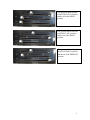
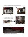
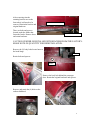
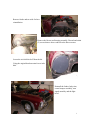
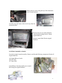
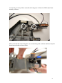
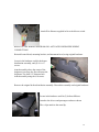
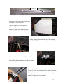
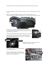
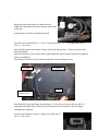
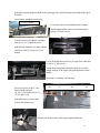
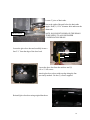
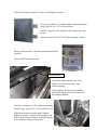
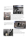
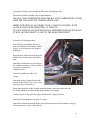
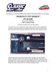
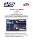
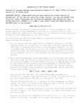
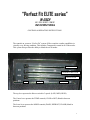
“Perfect Fit ELITE series”
IN-DASH
HEAT/ COOL/ DEFROST / COMFORT
1967 CHEVROLET IMPALA
CONTROL & OPERATING INSTRUCTIONS
The controls on your new “Perfect Fit” system. Offers complete comfort capabilities in
virtually every driving condition. This includes Temperature control in all of the modes.
This system also provides the ability to blend the air all modes .
FAN SWITCH
TEMPERATURE LEVER
MODE LEVER
A/C
DEF
FLOOR
The top lever operates the blower switch in 3 speeds. (LOW, MED, HIGH)
The Center lever operates the TEMP controls (COLD to HOT) blend in between
positions
The lower lever operates the MODE controls (DASH, DEFROST, FLOOR) blend in
between positions
1
This picture depicts the unit
in full COLD (A/C) position
and the air in the DASH
position
This picture depicts the unit
in full HOT (A/C) position
and the air in the DASH
position
This picture depicts the unit
in full COLD(A/C) position
and the air in the DEFROST
position
2
INSTALLATION INSTRUCTIONS
1967 CHEVROLET IMPALA
Congratulations!! You have just purchased the highest quality, best performing A/C
system ever designed for you Classic Car. To obtain the high level of performance and
dependability our systems are known for, pay close attention to the following
instructions.
Before beginning the installation check the box for the correct components.
Evaporator
Heater Duct Assembly
Inlet Air Block Off Assembly
Firewall Block Off Assembly
Flex hose 2” dia. (4) 2’, (1) 4’, (1) 52”
Sack Kit Hardware (2)
Sack Kit Control
Glove box
IMPORTANT INFORMATION
1.
2.
3.
1.
2.
3.
4.
5.
6.
Before starting, read the instructions carefully and follow proper sequence.
Check condition of engine mounts. Excessive engine movement can damage
hoses to A/C, heater, radiator, transcooler, and power steering systems.
Before starting, check vehicle interior electrical functions. i.e. interior lights,
radio, horn, etc. When ready to start installation, disconnect battery.
Fittings. Use one or two drops of lubricant on O’rings, threads and rear of bump
for O’ring where female nut rides. Do not use thread tape or sealants.
Always use two wrenches to tighten fittings. Try holding in one hand while
squeezing together while other hand holds fitting in position.
Shaft seals in a small percentage of compressors will require as much as 3-4
hours run time to become leak free.
Compressors supplied in our complete systems are filled with proper amount of
oil.
Compressor requires technician to hand turn 15-20 revolutions before and after
charging with liquid from a charging station before running system.
Compressors with damaged reed valves cannot be warranted.
Should you have any technical questions, or are suspect of missing, or defective
parts, call us immediately. Our knowledgeable staff will be glad to assist you.
3
YOU CAN NOW BEGIN THE INSTALLATION
Remove Glove box door, glove box, retain glove box
and original hardware. Remove radio, set aside for
reinstall. Retain original hardware.
Remove screws from the fresh air door control
bracket. Retain original hardware.
Let cable assembly drop the floor.
Disconnect battery and remove.
Remove the hood.
Retain original hardware.
The bolts for the inner fender liner must be removed and retained. Remove the passenger’s
front wheel.
BOLTS INNER FENDER
BOLTS AROUND
WHEEL OPENING.
BOLTS ON TOP OF
FENDER LINER
4
Carefully remove the following components as shown in the pictures below.
Retain all components and original hardware.
TURN SIGNAL ASSEMBLY
LIGHT BEZEL
CORNER BUMPER ASSEMBLY
Remove the corner bumper assembly. The
bolts are located as shown in the picture.
BOLTS
The body trim needs to be removed along the lower side as shown.
BODY TRIM
Carefully snap off the trim. Caution: do not scratch paint.
5
After removing trim the
retaining bracket next to the
front wheel well needs to be
removed. Retain the bracket and
original hardware.
RETAINING BRACKET
There are bolts and spacers
located under the fender that
fasten the fender. Remove these
and retain hardware.
BOLTS AND SPACERS
CAUTION: FENDER IS INSTALLED WITH SPACERS FROM THE FACTORY.
MAKE NOTE OF QUANTITY FOR REINSTALLATION.
Remove the (2) body bolts located next to
the hood hinge.
BOLT
Retain bolts and spacers.
BOLT
Remove the body bolt behind the passenger
door. Retain the original hardware and spacers.
Remove and retain the (4) bolts on the
radiator bulkhead.
6
Remove fender and set aside for later
reinstallation.
Remove the blower and housing assembly. Discard and retain
(2) screws that are above and below the blower motor.
Locate the air inlet block off from the kit.
Using the original hardware attach over inlet
hole.
Reinstall the fender, body trim,
corner bumper assembly, turn
signal assembly and the light
bezel.
7
DRAIN COOLANT FROM RADIATOR.
Remove Heater hoses from heater coil at
firewall.
Heater hoses
Disconnect electrical plug at
resistor.
Pull heater assembly away
from the firewall.
Disconnect the (2) control
cables from the box. Discard
the heater and the mounting
hardware.
Locate wire assembly that plugged into the original blower switch. Cut all but the brown
wire as far back as you can.
Cut the brown wire at the plug. And attach a male insulated spade connector.
8
Remove the (4) screws along the top of the instrument
bezel. Retain hardware.
Carefully snap the bottom of the bezel away from the
instrument panel.
Remove the (4) screws that attach the
control head mounting bracket. Retain
original hardware.
Remove control head. Retain original
hardware.
CONTROL MODIFICATIONS:
Locate the original control assembly. Remove and discard following components. Retain all
original hardware.
(1) Original Blower Switch
(2) Heat Cable
(3) Temp Cable
Attach Blower Switch assembly on to control
head using the original hardware.
9
As shown in picture it is necessary to rotate the assembly and slide over the screw that will be
under the switch. This screw will need to be
tightened with a wrench.
Locate in the control sack kit the Connecting Wire
and (1) 3/16” push nut.
Hook the wire through blower switch hole in the
lever and then over the Control Lever. Use push
nut to hold the connecting wire.
The next process is as simple as connecting cables to your OEM control head, placing control
head upside down.
CONNECTIONS ARE FROM UNDERSIDE OF CONTROL HEAD
Locate your E-Z Wire harness (green harness) from your control sack kit . Insert cable integrator
labeled MODE CONTROL ( green, yellow, blue wires ) and attach to the bottom arm of your
OEM control head. Place loop over post and attach with (1) push nut provided. Next attach (1)
cable clip provided to control bracket and tighten on OEM control head where the OEM cable
was attached previously. Make certain the cable integrator is flush with OEM control head
assembly as shown on next page.
Locate your E-Z Wire harness (green harness) from your control sack kit . Insert cable integrator
labeled TEMP CONTROL ( purple, brown, white wires) and attach to the middle arm of your
OEM control head. Place loop over post and attach with (1) push nut provided. Next attach (1)
cable clip provided to control bracket and tighten on OEM control head where the OEM cable
10
was attached previously. Make certain the cable integrator is flush with OEM control head
assembly as shown.
Make certain that the control integrators are not interfering with each other and located upside
down from each other as shown below.
11
Attach Wire Harness supplied in kit to the blower switch.
REFER TO THE WIRING DIAGRAM ON LAST PAGE FOR PROPER WIRING
CONNECTIONS
Reinstall control head, mounting bracket, and instrument bezel, using original hardware.
Locate in the hardware sack kit the heater
distribution assembly, and (2) #10 x ¾”
screws.
Attach assembly above the center of the
doghouse just where the firewall meets the
dog house. Pre drill 1/8” diameter hole.
Attach assembly using the #10 screws.
Remove the original defrost distribution assembly. Discard the assembly and original hardware.
Locate in the hardware sack kit (2) defrost diffusers.
Attach to the drivers and passengers outlets as shown.
The s-clips attach to the metal lip.
12
S-CLIPS (2)
Locate on the last page of the instructions
a template. Cut out as shown.
Tape the template to the firewall as
shown in the picture.
Notch the corner of the heater opening,
and drill (2) 7/8” diametre holes.
Using a pair of pliers flatten the lip of the opening
under the 7/8” holes.
Locate in the hardwae sack kit (2) heater bulkheads.
Insert bulkheads from the inside of the car. Attach
with nuts, tighten nuts.
Locate the (2) 5/8” diameter heater hoses provided in kit.
Locate (2) worm gear clamps from the hardware sack kit.
The longest heater hose attaches to the fitting on right
using (1) of the worm gear supplied.
13
The shortest heater hose attaches to the fitting on left using (1) of the worm gear clamps.
Locate the evaporator, (1) 1ft of 2” diameter flex duct, (1) 2ft. of 2” diameter flex duct, and (2)
ty-raps.
Place unit on bench and attach the 2ft duct to the left hose adaptor using (1) ty-rap.
Attach the 1ft duct to the right hose adaptor using (1) ty-rap. As shown in picture on next page.
The next step is to install the evaporator into the car. The picture to
the right shows the unit from the front. Note the 2ft duct lays over the
top of the unit as it is installed.
Lift unit up and behind the instrument panel. The picture on next page
shows the engine side of the firwall. The (2) studs insert into the
original heater mounting holes. Attach using (2) ¼”-20 flange nuts
provided in the hardware sack kit.
2 ft flex duct
1 ft flex duct
Attach th flex duct from the heater outlets to the
distribution assembly. As shown.
Locate in the kit (1) 2ft 2” diameter flex hose and
(1) 2” diameter flex hose.
Attach the 2ft hose from the left defrost outlet to
the drivers side defrost diffuser. Attach to diffusser
using (1) #8 x 3/8” pan head screw.
1ft DUCT HOSE
2FT DUCT HOSE
14
Attach the 1ft hose from the right defrost outlet to the passenger side defrost diffuser. Attach to
diffusser using (1) #8 x 3/8” pan head screw.
Route the temperature control cable along the firewall and out the large hole as shown in the
picture below.
Locate in the hardware sack kit (1) #10 x ¾” tek screw.
Located under the glove box opening the front support
bracket. Using the #10 screw attach to the bottom of the
instrument panel.
15
Route the heater hoses that were attached to the
bulkheads, and attach to the heater fittings on the front
of the unit.
Attach using (2) worm gear clamps provided.
Locate the firewall blockoff, (1) ¼”-20 x 5/8 hex head screw, (3) ¼”-20 flange nuts, and (3)
#10 x ¾ “ tek screws.
Insert the Blue clutch wire and the Temp control cable through the ½” plastic grommet in the
firewall blockoff.
Slide the blockoff over the suction tube, heater bulkheads, and insert the liquid tube through the
hole in the bulkhead.
The blockoff will slide over the studs at the bottom of the mounting bracket.
#10 SCREW
¼” – 20 X 5/8
SCREW & NUT
#10 SCREWS
STUDS
Attach blockoff using the flange nuts at bottom, (3) #10 tek screws across the top, and (1) ¼”
bolt and nut from the inside of firewall on the bottom left. Seal around a/c hoses using the
insulation tape supplied.
Locate in the hardware sack kit (1) single face outlet and (2)
#10 x ¾” tek screws.
16
Attach the housing under the dash on the passenger side. Attach housing to the right of the glove
box door.
Insert louver assembly into housing.
#10 TEK SCREWS
Locate the center face distribution hose adaptor.
Attach adapter under center of instrument panel
using (2) #10 tek screws.
Locate Center Louver Bezel Assembly
and (2) #8 x 3/8” pan head screws.
Attach bezel assembly over hose adaptor
and fasten with (2) #8 screws. (2) on
bottom.
Locate in the hardware sack kit (1) single face outlet and
(2) #10 x ¾” tek screws.
Attach the housing under the dash on the drivers side.
Attach housing to the right of the parking brake release
handle.
Insert louver assembly into housing.
Locate (4) pieces of the 2” flex
duct from the unit box.
(1) 4ft, (1) 3ft cut the duct to 32”,
(1) 3ft, and (1) 2ft.
DRIVERS
4FT
CENTER LT.
32”
CENTER RT.
3FT
PASSENGER
2FT
Attach the hoses as shown and
route to the dash louvers.
Reattach the fresh air door cable using original hardware.
17
Locate 6” piece of drain tube.
Just to the right of the unit below the drain tube
nipple. Drill (1) 13/16” diameter hole and insert the
drain tube.
DRAIN NIPPLE
NOTE: HOLE MUST BE BELOW THE DRAIN
TUBE NIPPLE TO ALLOW PROPER
CONDENSATION DRAIN.
Locate the glove box door and carefully locate a
line 2 ¾” from the edge of the door back.
2 ¾”
Locate the glove box from the unit box and (3)
#10 x ¾” tek screws.
Attach glove box to door with top edge along the line
previously marked. Use the (3) screws supplied.
Reinstall glove box door using original hardware.
18
Caution: Carefully check under the Instrument Panel for all cables, electrical harness, or Flex
hoses that might interfere with the safe operation of the vehicle.
Locate the Water Valve and (3) worm gear clamps.
Attach the Temperature cable to the water valve using the
cable clip supplied on the water valve.
Supply line from the engine is attached to the left heater
hookup tube. Cut 6” off end of the return line and install
the water valve using (3) worn gear clamps as shown
above.
Note: It is recommended that you replace heater hoses
from the engine to the hookup tubes.
Installation of the interior components is complete. We will now install the
under hood portion of the system.
5/8”
There needs to be a 1” hole for the
discharge tube to come through the
radiator support.
Locate on the passenger side of the
radiator support. The center of the hole to
be drilled. Drill a 1” hole to the
dimensions as shown.
6 7/8”
Locate the Receiver Drier, Drier Mounting Bracket,
Aluminum Liquid tube, (2) #6 o-rings, and (2)
#10 x 3/8” hex head screws.
Install the Receiver drier to the condenser as to
allow the Liquid Tube to attach as shown.
19
Install a few drops of mineral oil to the o-ring fittings, and secure.
Locate the Condenser, (2) right condenser mounting brackets
(short), and (4) #10 x 3/8” hex head screws.
Attach (1) bracket to the condenser 3rd hole from the top as
shown.
Attach the other bracket 4th hole from the bottom as shown
Remove and retain the (5) bolts that attach the hood latch
assembly.
Remove hood latch and set aside.
SHROUD BOLTS
Loosen the radiator shroud bolts. These
bolts are located on both sides of the
radiator opening.
Slide condenser down in front of radiator.
Insert the brackets between the shroud and
the radiator bulkhead.
Locate the Condenser, (1) left condenser mounting
bracket (long), and (2) #10 x 3/8” hex head screws.
Slide bracket between shroud and the radiator
bulkhead. Attach (1) bracket to the condenser 4th
hole from the bottom as shown. Attach the bracket
to the condenser using the #10 screws.
20
Locate the #8 discharge tube, and (1)
#8 o-ring.
Route tube through the hole and attach
to condenser using the o-ring and a few
drops of mineral oil.
Insert top bracket between shroud and the radiator bulkhead.
Attach bracket to the condenser in the top hole as shown.
Attach the bracket to the condenser using the #10 screws.
Slide condenser assembly to the left and up and down so that
the tube comes through the hole in the center.
Tighten shroud to clamp brackets to radiator bulkhead.
Locate the #6 liquid tube and (1) #6 o-ring.
Loosely attach tube to drier. Using the
other end locate and drill (1) hole 11/16”
diameter.
Insert the bulkhead fitting through the hole and
attach using the nut provided.
Tighten fitting and bulkhead securely.
Locate Hi-Low pressure switch ,electrical boot and
attach to top of the receiver drier using a few drops
21
of mineral oil. Route wires through the hole along the discharge tube.
Reinstall hood latch assembly using original hardware.
INSTALL THE COMPRESSOR ADAPTER KIT AND COMPRESSOR AT THIS
TIME PER THE MANUFACTURERS DIRECTIONS.
NOTE: THIS INSTALL IS CORRECT FOR A 350CID V8 ENGINE, WITH
ALTERNATOR ON DRIVERS SIDE OF VEHICLE.
IF YOUR VEHICLE IS EQUIPTED WITH A DIFFERENT ENGINE PACKAGE
IT WILL BE NECESSARY TO ROUTE THE HOSES DIFFERENT
Locate the #10 refrigerant hose.
Attach 90 deg. end without the service
port to #10 fitting at the firewall. Attach
using (1) #10 o-ring and a few drops of
mineral oil.
Route the hose inside the fender forward
and out between the battery and fender
liner.
Attach the end with the service fitting to
the compressor using (1) #10 o-ring and a
few drops of mineral oil.
Tighten securely.
Locate the liquid hose, and (2) #6
o-rings.
Attach the 90 deg. fitting with the male
threads to the firewall. Use (1) #6 o-ring
and a few drops of mineral oil.
Route hose inside the fender forward around the battery and connect the end with
the 45deg. fitting to the liquid fitting on the radiator core support.
Attach using #6 o-ring and a few drops of mineral oil. Tighten securely.
Locate the #8 discharge hose and (2) #8 o-rings.
Attach the end with the straight fitting to the discharge tube from the condenser using (1)
#8 o-ring and a few drops of mineral oil.
22
Attach #8 refrigerant hose with service port end to the compressor using (1) #8 o-ring and a
few drops of mineral oil. Tighten securely.
ELECTRICAL WIRING
The wiring of our ELITE series has been simplified. We have taken several
steps to ensure easy connection of all actuators to state of the art ECU board
that will control all heat, A/C, defrost functions.
---First locate the (3) Wiring harnesses from the control sack kit each
harness is color coded(yellow, blue, orange)
---Locate the ECU on the evaporator unit (page4 fig.1 & 2)
---Locate the BLUE wiring harness and plug on end into the color
correct connection on the ECU, plug other end into correct color
coded actuator on evaporator
---Locate the YELLOW wiring harness and plug on end into the color
correct connection on the ECU, plug other end into correct color
coded actuator on evaporator
---Locate the ORANGE wiring harness and plug on end into the color
correct connection on the ECU, plug other end into correct color
coded actuator on the water valve(refer to page 10 for correct water
valve installation)
---Locate your control harness (GREEN) plug the connector to the
ECU in the correct color coded plug
----Locate the main power wiring harness (refer to wiring diagram for
specific details pg 10)
----Plug the RED connection into the RED coded plug on the ECU
CAUTION:
23
Make certain you plug the RED connection to the RED
connection on theECU,
Failure to make correct connection will lead to ECU board
failure and will NOT be covered under warranty
CALIBRATING YOUR CONTROL HEAD TO THE EVAPORATOR UNIT
Please reaad through this portion of the instructions before starting, if at any reason you
feel the unit did not calibrate correctly, turn unit off and rerun calibration process.
Insert calibration key into six pin connectior on ECU board.
Move the MODE ( bottom)lever to the far right.
Move the TEMP (middle) lever to the far left.
Power up the Board (turn fan switch to LOW) LED on calibration key comes ON
After 1 second the LED turns OFF
After 1 second the LED comes ON
Move the MODE (bottom) lever to far left.
After 1 second the LED turns off
After 1 second the LED truns on
Move the TEMP (middle) lever to the far right.
After 1 second the LED turns OFF
After 1 second the LED turns ON
The motor calibration starts, one way then the other, the doors will stop at their
midpoints. (during this time do not touch the control head)
LED turns OFF
Turn power OFF (blower sitch)
Remove the calibration key and store.
24
The calibration of theunit to your specific control head is complete. You are now
ready to use your system.
25
26
27
Reinstall hood, battery tray and battery, using original hardware. Refill radiator.
Carefully check the hood alignment for proper fit.
THE ENGINE COMPARTMENT OF YOUR SYSTEM IS COMPLETE.
THE UNIT IS READY FOR EVACUATION AND CHARGING.
THIS SHOULD BE DONE BY A QUALIFIED AND CERTIFIED AIR
CONDITIONING TECHNICIAN.
NOTE: COMPRESSOR IS SUPPLIED WITH THE
CORRECT OIL CHARGE. DO NOT ADD OIL TO SYSTEM.
134A SYSTEMS
24 oz OF REFRIGERANT
Recommend that power fuse is 25 amp minimum
Congratulations you have completed the install of your
CLASSIC AUTO AIR “PERFECT FIT SERIES” system.
28
29
30
IMPORTANT
CAUTION: WATER VALVE MUST BE INSTALLED PER
THE INSTRUCTIONS.
Classic Auto Air has done extensive testing on the correct method to install the water valve in order to get a
repeatable and progressive temperature control.
Locate the bottom connection from the evaporator/heater unit off of the firewall and attach a 6” piece of
5/8” dia. heater hose with the supplied hose clamp. Next attach the inlet side of the water valve using
another supplied hose clamp, (make sure the arrow on the water valve points toward the engine) Attach a
heater hose from the outlet side of the water valve and route to the connection on the water pump.
NOTE: WATER VALVE = WATER PUMP
FROM HEATER CORE
TO WATER PUMP
COOLANT FLOW
CAUTION: WATER VALVE MUST BE INSTALLED ON HEATER LINE ROUTED TO
WATER PUMP.
NOTE: COMPRESSOR PURCHASED WITH KIT IS
SUPPLIED WITH THE CORRECT OIL CHARGE. DO NOT
ADD OIL TO SYSTEM.
134A SYSTEMS
24 oz OF REFRIGERANT
Recommend that power fuse is 25amp minimum
31