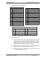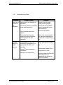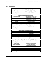
1
Installation and Operation Manual ASP-101-02-x Surround Sound Processor Document # 540183 7300 Industry Drive, North Little Rock, AR 72117 Phone: 501-955-2929 Fax: 501-955-2988 www.audiointl.com Audio International, Inc. ASP-101-02-x Installation & Operation Document Revision History Rev. Level Date Description IR 6/2000 Initial Release Reference Documents Document # Description 522305 Rev IR ASP-101-02-x Outline Drawing 320626 Rev IR ASP-101-02-x Mechanical Drawing Service Bulletin List Service Bulletin # Subject Manual Revision Revision Date Table of Illustrations Illustration # Description Page # 2.3 Typical System Block Diagram 5 7.0 Reference Drawings 14 PROPRIETARY INFORMATION NOTICE: Despite any other copyright notice, this document and information disclosed herein contains confidential, proprietary designs owned by Audio International, Inc. Neither this document nor the data contained herein shall be reproduced, used, or disclosed to anyone without the written authorization of Audio International, Inc. Document #540183, Rev IR, 6/2000 Page 1 of 14 Audio International, Inc. ASP-101-02-x Installation & Operation Table of Contents 1.1 1.2 1.3 Description General Information . . . . . . . . . . . . . . . . . . . . . . . . . . . . . . . . Introduction . . . . . . . . . . . . . . . . . . . . . . . . . . . . . . . . . . . . . . . Purpose of the Equipment . . . . . . . . . . . . . . . . . . . . . . . . . . . . Operational Features . . . . . . . . . . . . . . . . . . . . . . . . . . . . . . . . Page 3 3 3 4 2.1 2.2 2.3 2.4 2.5 Application . . . . . . . . . . . . . . . . . . . . . . . . . . . . . . . . . . . . . . . Introduction . . . . . . . . . . . . . . . . . . . . . . . . . . . . . . . . . . . . . . . Typical Application . . . . . . . . . . . . . . . . . . . . . . . . . . . . . . . . . . Typical System Block Diagram . . . . . . . . . . . . . . . . . . . . . . . . . Multiple Unit Configurations . . . . . . . . . . . . . . . . . . . . . . . . . . . Data Bus Control . . . . . . . . . . . . . . . . . . . . . . . . . . . . . . . . . . . 4 4 4 5 5 5 3.1 3.2 3.3 3.4 3.5 3.6 3.7 3.8 Installation . . . . . . . . . . . . . . . . . . . . . . . . . . . . . . . . . . . . . . . Prior to Installation . . . . . . . . . . . . . . . . . . . . . . . . . . . . . . . . . . Unpacking and Inspection . . . . . . . . . . . . . . . . . . . . . . . . . . . . Cautions & Warnings . . . . . . . . . . . . . . . . . . . . . . . . . . . . . . . Wiring Requirements . . . . . . . . . . . . . . . . . . . . . . . . . . . . . . . . Physical Characteristics . . . . . . . . . . . . . . . . . . . . . . . . . . . . . . Mating Connector Information . . . . . . . . . . . . . . . . . . . . . . . . . Pinout Assignments and Descriptions. . . . . . . . . . . . . . . . . . . . Post-Installation Test . . . . . . . . . . . . . . . . . . . . . . . . . . . . . . . . 6 6 6 7 7 8 9 10 10 Operation . . . . . . . . . . . . . . . . . . . . . . . . . . . . . . . . . . . . . . . . Power Up . . . . . . . . . . . . . . . . . . . . . . . . . . . . . . . . . . . . . . . . Source Switching . . . . . . . . . . . . . . . . . . . . . . . . . . . . . . . . . . . 11 11 11 Troubleshooting . . . . . . . . . . . . . . . . . . . . . . . . . . . . . . . . . . . General Troubleshooting Procedures . . . . . . . . . . . .. . . . . . . . Troubleshooting Chart . . . . . . . . . . . . . . . . . . . . . . . . . . . . . . . 11 11 12 6.0 Specifications . . . . . . . . . . . . . . . . . . . . . . . . . . . . . . . . . . . . 13 7.0 Reference Drawings . . . . . . . . . . . . . . . . . . . . . . . . . . . . . . . . 14 Section 1.0 2.0 3.0 4.0 4.1 4.2 5.0 5.1 5.2 Document #540183, Rev IR, 6/2000 Page 2 of 14 Audio International, Inc. ASP-101-02-x Installation & Operation ASP-101-02-x Surround Sound Processor 1.0 General Information 1.1 Introduction This manual contains information for the proper application, installation, and operation of the Audio International, Inc. (AI), Surround Sound Processor, Model # ASP-101-02-x. The “-x” suffix in the model number designates the type of connector utilized. Also included are relative physical and electrical characteristics of the unit. 1.2 Purpose of the Equipment The Surround Sound Processor has been specifically designed to meet the special requirements of aircraft use. The unit is comprised of four functional modules; audio control, cabin audio surround processor, digital to analog audio conversion, and FiberLink interface. The ASP-101-02-x accepts audio inputs from the entertainment source equipment. Using commands issued from switch panels, LCD touch screens or electroluminescent touch screen panels, the unit distributes the audio to cabin speakers. Document #540183, Rev IR, 6/2000 Page 3 of 14 Audio International, Inc. 1.3 Operational Features q q q q q q q q q q q 2.0 ASP-101-02-x Installation & Operation Allows multiple source audio inputs to be selected and routed independently to multiple audio devices. FiberLink cabin audio output. Integrated cabin audio surround sound processor. 4 digital audio source inputs to integrated surround sound processor. 1 analog audio input to integrated surround sound processor. 1 digital audio to analog audio converter. Control, configuration, and interface with other components via Audio International’s proprietary RS-485 serial data bus. 3 binary unit ID pin inputs identify each module on the data bus in a multi-unit configuration (up to 8 units total on the same AI proprietary RS-485 data bus). Separate PA audio and PA key inputs provide for entertainment audio override capability when activated for both the integrated cabin audio surround sound processor and the integrated 16 x 16 internal audio multiplexer. Power-up defaults are software configurable for each audio output. Lightweight, rugged aircraft design. Application 2.1 Introduction The ASP-101-02-x is part of a complete cabin audio entertainment system. The application of the unit is specific to a particular aircraft based upon the desires of the customer or designer. 2.2 Typical Application The unit provides a switching matrix for cabin entertainment systems utilizing multiple source audio inputs and outputs. Since it resides on AI’s proprietary RS-485 data bus, any switch or control device can independently select from amongst the input sources. A dedicated FiberLink cabin audio output is provided via the integrated cabin audio surround sound processor. Document #540183, Rev IR, 6/2000 Page 4 of 14 Audio International, Inc. 2.3 ASP-101-02-x Installation & Operation Typical System Block Diagram BUFFER BUFFER BUFFER OPTICAL LOOP OUTPUTS BUFFER FIBER OPTIC DIGITAL AUDIO INPUTS 4-INPUT DIGITAL AUDIO SELECTOR ANALOG INPUT PA INPUT DATA BUS I/O 2.4 AUDIO SURROUND SOUND PROCESSOR TM FIBERLINK INTERFACE DIGITAL CABIN AUDIO OUTPUT INPUT LEVEL CONTROL RS485 DATA BUS INTERFACE Multiple Unit Configurations There is ONLY one (1) audio source input and output possible on each ASP-101-02-x. If more than one (1) audio input or output is needed, multiple-unit configurations are possible via AI’s proprietary RS-485 serial data bus. This allows selection of any audio source from any location provided the proper audio source inputs are correctly routed to each ASP-101-02-x unit as needed. The number of possible units in a system is dependent on other modules used within the cabin audio system, up to eight (8) can be used on the same AI proprietary RS-485 data bus segment. 2.5 Data Bus Control There are no controls on the ASP-101-02-x. Switching control of the unit is handled by commands sent via AI’s proprietary RS-485 serial data bus. Some features are set upon installation using an external PC (typically a laptop) and an MSM2912-01-x, RS-232 / RS-485 Converter Module. A software program designed by Audio International specifically for this task sets the power-up state for each audio output, trim levels for each audio input source, and cabin audio Surround Sound Processor and FiberLink network specifications. Document #540183, Rev IR, 6/2000 Page 5 of 14 Audio International, Inc. 3.0 ASP-101-02-x Installation & Operation Installation 3.1 Prior to Installation The ASP-101-02-x is a simple module to install. Prior to installation the following items should be considered: 3.1.1 During the design and layout of the aircraft cabin, careful consideration of the location of this and all other audio modules is necessary. Some of the items to consider include: • • • • • • • • Space Proximity to other devices (i.e. source equipment) Available power supply Length of cable runs Environmental conditions (temperature, humidity, etc.) Location of other aircraft systems (i.e. oxygen delivery) Access for service repair (if applicable) Convenience for user interface (if applicable) 3.1.2 The module shall be installed to conform to the standards designated by the customer, installing agency, or other specified requirements. 3.1.3 Select a mounting location for the ASP-101-02-x prior to installation. User access is NOT a consideration when placing unit into the suitable mounting location. Refer to Section 7.0 for dimensions and attachment points. The unit shall be bonded to the aircraft frame with a bonding resistance of less than 0.001-ohms. 3.2 Unpacking and Inspection 3.2.1 Carefully open the packaging and remove the ASP-101-02-x. Verify that all components have been included in the package per the packing list. Inspect the unit for shipping damage. 3.2.2 If damage has occurred during shipping, a claim should be filed with Audio International within 24 hours and a Return Request Authorization Number shall be obtained from AI. Refer to the front cover of this manual for address and telephone number of Audio International, Inc. Repackage the unit in its original packaging materials and return it to AI following instructions given by the AI representative. If no return is necessary, retain the packing list and the packing materials for storage. Document #540183, Rev IR, 6/2000 Page 6 of 14 Audio International, Inc. 3.3 ASP-101-02-x Installation & Operation Cautions & Warnings 3.3.1 All analog audio output lines from the Surround Sound Processor unit shall be shielded and properly grounded. Analog audio input lines shall be shielded and grounded at the source, unless indicated otherwise. Avoid placing cables near high power wires. 3.3.2 It is important to do a pin-to-pin power and ground check on all connectors. Ensure that power and ground are applied only where specified. Damage to the unit can result if power or ground is applied to the wrong points. 3.3.3 DO NOT connect or disconnect the unit while power is applied. 3.3.4 DO NOT connect or disconnect any inputs or outputs when power is applied to the unit. 3.3.5 DO NOT remove any factory-installed screws. Damage to the unit can result and void any warranties. 3.3.6 ESD (Electro Static Discharge) guidelines shall be followed. 3.4 Wiring Requirements The installing agency shall supply and fabricate all external cables and connectors. The length and routing of external cables should be carefully studied and planned before attempting installation of the equipment. Allow adequate space for installation of cable and connectors. 3.4.1 Digital Audio / FiberLink Lines All digital audio / FiberLink wiring shall be 100/140 µm (core/cladding) multi-mode fiber optic cabling. All fiber optic connectors/couplers shall use ceramic ferrules to minimize adverse reflection effects. BRAND-REX P/N: OC-1011 or equivalent fiber optic cabling shall be used for all digital audio / FiberLink wiring. 3.4.2 Analog Audio Lines All analog audio wiring shall be 22 AWG, MINIMUM, twisted shielded cable unless otherwise specified. All audio input and output lines require twisted shielded cable with the cable shields grounded at the source. Shield continuity shall be maintained through all production breaks. Document #540183, Rev IR, 6/2000 Page 7 of 14 Audio International, Inc. ASP-101-02-x Installation & Operation 3.4.3 Power Wires All power and ground wires shall be 20 AWG, MINIMUM. Power ground wires shall be grounded within twelve inches of the unit. Protect power wires with circuit breakers or fuses located close to the electrical power source bus. 3.4.4 AI’s Proprietary RS-485 Serial Data Bus The ASP-101-02-x is designed to interface with other Audio International equipment via AI’s proprietary RS-485 serial data bus. The data bus shall be implemented using a twisted shielded pair cable in accordance with MIL-DTL-27500 or equivalent. The wire size for the conductors in this cable shall be 22 AWG, MINIMUM. The shield shall be connected to a shield pin or to ground at one end of the connection between devices. Shield terminations shall be made as close to the connector pin as possible. Maximum derivation distance from data bus splice connections to actual connector of each data bus device is 24 inches in length. All modules on AI’s proprietary RS-485 serial data bus shall be connected in a daisy-chain configuration. 3.4.5 MIL-SPEC Requirements All wires shall be in accordance with MIL-W-22759 or equivalent. Twisted shielded cable shall be in accordance with MIL-DTL-27500 or equivalent. 3.4.7 Clearance and Separation Requirements When running cables, avoid sharp bends and placing cables near aircraft control cables. Maintain a MINIMUM clearance of three (3) inches from any control cable. If wiring is run parallel to combustible fluid or oxygen lines, maintain a separation of six (6) inches between the lines. 3.5 Physical Characteristics 3.5.1 The ASP-101-02-x should be located away from heat sources, magnetic fields, direct sunlight, and areas with excessive dust and/or moisture. The unit shall NOT be mounted to the skin of the aircraft. 3.5.2 Refer to Section 7.0 for unit dimensions and mounting hole sizes. Document #540183, Rev IR, 6/2000 Page 8 of 14 Audio International, Inc. ASP-101-02-x Installation & Operation 3.5.3 The unit shall be rigidly mounted to its location using the appropriate fastening hardware supplied by the installing agency. 3.5.4 When mounting the unit to the aircraft’s frame, allow sufficient space for mating connectors. 3.5.5 ASP-101-02-x Configuration Options Audio Each audio input may have the following configuration options specified: • Input Level adjustment from 0% to 100% of full maximum in increments of 2% Each audio output (amplifier and headphone) may have the following configuration options specified independently: • • • Power-up volume level from 0% to 80% in increments of 10% Power-up bass level from 0% to 100% in increments of 25%. Power-up treble level from 0% to 100% in increments of 25%. 3.6 Mating Connector Information 3.6.1 ASP-101-02-x Mating Connectors Model # Pin # ASP-101-02-1 P1 P2-P13 Description RD37F10JVL0 Female Plug (Positronic) Mates with ST Series Optical Cable 501380-2 AMP or Equivalent ASP-101-02-2 P1 DCMA-37S Female Plug M85049/48-1-4 Backshell D20419-18 Male Screwlock P2-P13 Mates with ST Series Optical Cable 501380-2 AMP or Equivalent ALL CONNECTORS TO HAVE LOCK TAB SETS ON UNIT. Document #540183, Rev IR, 6/2000 Page 9 of 14 Audio International, Inc. 3.7 ASP-101-02-x Installation & Operation Pinout Assignments and Descriptions Pin # 1 2 3 4 5 6 7 8 9 10 11 12 13 14 15 16 17 18 19 P1 Pinout Chart Description +28 VDC Input (Digital) Ground Input Data Bus A Data Bus B Data Bus Shield Unit ID 1 Unit ID 2 Unit ID 4 ID Common PA Key Input PA Audio High Input PA Audio Low Input PA Audio Shield Input Left Analog Audio Input High Left Analog Audio Input Low Left Analog Audio Input Shield Right Analog Audio Input High Right Analog Audio Input Low Right Analog Audio Input Shield Pin # 20 21 22 23 24 25 26 27 28 29 30 31 32 33 34 35 36 37 Description Left Analog Audio Output High Left Analog Audio Output Low Left Analog Audio Output Shield Right Analog Audio Output High Right Analog Audio Output Low Right Analog Audio Output Shield Front Left Output High Front Left Output Low Front Right Output High Front Right Output Low Rear Left Output High Rear Left Output Low Rear Right Output High Rear Right Output Low Woofer Output High Woofer Output Low Center Output High Center Output Low Connector Functions P2 – P13 3.8 P2 Optical Input #1 P8 Optical Input #4 P3 Optical Output #1 P9 Optical Output #4 P4 Optical Input #2 P10 Optical Input (for Analog Out) P5 Optical Output #2 P11 Optical Output P6 Optical Input #3 P12 Fiberlink Input P7 Optical Output #3 P13 Fiberlink Output Post Installation Test 3.8.1 With the aircraft power “ON”, select an audio source unit and operate that unit to create audio signal to the ASP-101-02-x. Verify that an audio output is present at one of the audio output locations. Repeat this test for each audio source unit in the system. Repeat this test for each audio output location in the system. 3.8.2 Repeat the above tests using all control units in the aircraft (switch panels, IR Remotes, LCD touch-screen monitors, etc.) 3.8.3 Activate and speak into a microphone to verify that the PA audio overrides the entertainment audio. Document #540183, Rev IR, 6/2000 Page 10 of 14 Audio International, Inc. ASP-101-02-x Installation & Operation 3.8.4 All aircraft audio functions should be tested for proper operation. If all audio functions are operational, the ASP-101-02-x has been properly installed. Refer to Section 5.0, Troubleshooting, if problems are encountered. 4.0 Operation 4.1 Power Up Power to the unit is initiated when the aircraft power is turned on and remains on at all times. 4.2 Source Switching There are no direct controls on the unit. All functions are controlled through commands sent via AI’s proprietary RS-485 serial data bus. Switching audio sources from any location is accomplished through any user device designed to give selection choice – switch panels, LCD touch screens, remote controls, etc. 5.0 Troubleshooting 5.1 General Troubleshooting Procedures Many problems can be isolated with the following general techniques: • To verify power to the unit, recheck +28 VDC power is applied to the proper pins on the unit. Use a voltmeter to verify correct level. • To reset, remove power from the unit for at least one minute and reapply power to verify that the problem still exists. • Recheck all connections to the unit for security. Check all harness runs for possible pinching. Recheck all pin outs for application accuracy. Document #540183, Rev IR, 6/2000 Page 11 of 14 Audio International, Inc. 5.2 ASP-101-02-x Installation & Operation Troubleshooting Chart Problem Possible Cause Audio is not present in the speakers Audio source not selected or activated Problem selecting audio sources Solution Ensure an active audio source input is present Unit is not properly connected Ensure the unit has been to the audio source(s) properly connected to the audio source(s) Circuit breaker has been tripped Reset circuit breaker There has been a power failure while the respective entertainment unit was operating Refer to the entertainment unit operation manual to reactivate the corresponding unit Control panel or ASP unit improperly connected to AI’s proprietary RS-485 serial data bus Check each device for proper connections to data bus Device ID pins improperly connected Verify proper device ID pin connections on units Selection not responding Verify that data bus A and B connections are not swapped at any device on data bus segment Document #540183, Rev IR, 6/2000 Page 12 of 14 Audio International, Inc. 6.0 ASP-101-02-x Installation & Operation Specifications Housing Dimensions (l x w x h) Weight Physical Specifications Black Brushed Aluminum 9.4" x 10.5" x 2.4" 23.88 cm x 26.67 cm x 5.08 cm 2.5 lbs / 1.13 kg Power Requirement Specifications P7 (Entertainment) Amp Maximum @ +28 VDC Amp Nominal @ +28 VDC P10 (Digital) Amp Maximum @ +28 VDC Amp Nominal @ +28 VDC Operating Voltage +18 to + 32 VDC, Range +28 VDC Nominal Digital Audio Specifications Number of Audio Inputs 4 – Entertainment 1 – D/A Conversion Number of Audio 1 - FiberLink Outputs Analog Audio Input Specifications Number of Audio Inputs 1 Input Signal Level +1 to + 5 VRMS, +2 VRMS optimum (differential) Input Impedance 4.7 k-ohm / input Frequency Response 20 Hz – 20 kHz +/- 1 dB PA Audio Input +1 to +5 VRMS, +2 VRMS optimum @ 1 k-ohm Analog Audio Output Specifications (P6 & P9 only) Number of Audio 1 Outputs Output Power 530 mW / Channel RMS Output Impedance 50-ohm MINIMUM (common ground output) PA and Video Briefer Key Input Specifications Active Signal Type Ground Active Signal Level < +1.2 VDC Document #540183, Rev IR, 6/2000 Page 13 of 14 Audio International, Inc. 7.0 ASP-101-02-x Installation & Operation Reference Drawings The following diagrams show the unit dimensions and connector locations for the ASP-101-02-x. All dimensions are shown in inches. Document #540183, Rev IR, 6/2000 Page 14 of 14