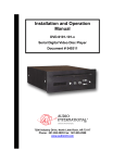
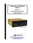
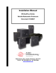
1
Installation & Operation Manual
A/V-9691-01(-02)-x
Audio/Video Distribution Unit
Document # 540250
a DeCrane Aircraft Company
7300 Industry Drive, North Little Rock, AR 72117
Phone: 501-955-2929 Fax: 501-955-2988
www.audiointl.com
Audio International, Inc.
A/V-9691-01(-02)-x Installation & Operation Manual
Document Revision History
Rev. Level
Date
Description
IR
02/2003
Initial Release
A
05/2003
Corrected Pinout
B
11/2003
Corrected Grounding Requirements (p13)
C
04/2004
Amended Wiring Requirements (sections 3.4.1 and
3.4.2) and data bus characteristics (3.6.2)
D
07/2004
Updated Outline Drawings, photo, and Reference
Drawings
Reference Documents
Document #
Description
523732 Rev C
A/V-9691-0x-x Outline Drawing
Service Bulletin List
Service
Bulletin #
Subject
Manual
Revision
Revision
Date
Table of Illustrations
Section #
Description
Page #
2.2
Block Diagram
10
4.3
LED Indicator Lights
29
8.0
Reference Drawings
32-33
PROPRIETARY INFORMATION NOTICE: Despite any other copyright notice, this document
and information disclosed herein contains confidential, proprietary designs owned by Audio
International, Inc. Neither this document nor the data contained herein shall be reproduced,
used, or disclosed to anyone without the written authorization of Audio International, Inc.
Document # 540250, Rev D, 07/2004
Page 1 of 33
Audio International, Inc.
A/V-9691-01(-02)-x Installation & Operation Manual
Table of Contents
Section
1.0
1.1
1.2
1.3
1.4
Description
General Information . . . . . . . . . . . . . . . . . . . . . . . . . . . . .
Introduction . . . . . . . . . . . . . . . . . . . . . . . . . . . . . . . . . . . . .
Purpose of the Equipment . . . . . . . . . . . . . . . . . . . . . . . . . .
Operational Features . . . . . . . . . . . . . . . . . . . . . . . . . . . . . .
Optional Equipment . . . . . . . . . . . . . . . . . . . . . . . . . . . . . . .
Page
3
3
3
3
4
2.1
2.2
Application . . . . . . . . . . . . . . . . . . . . . . . . . . . . . . . . . . . . .
Introduction . . . . . . . . . . . . . . . . . . . . . . . . . . . . . . . . . . . . .
Block Diagram - Typical Application. . . . . . . . . . . . . . . . . . .
5
5
10
3.0
Installation . . . . . . . . . . . . . . . . . . . . . . . . . . . . . . . . . . . . .
3.1 Prior to Installation . . . . . . . . . . . . . . . . . . . . . . . . . . . . . . . .
3.2 Unpacking and Inspection . . . . . . . . . . . . . . . . . . . . . . . . . .
3.3 Cautions & Warnings . . . . . . . . . . . . . . . . . . . . . . . . . . . . .
3.4 Wiring Requirements . . . . . . . . . . . . . . . . . . . . . . . . . . . . . .
3.5 Physical Characteristics . . . . . . . . . . . . . . . . . . . . . . . . . .
3.6 Electrical Characteristics . . . . . . . . . . . . . . . . . . . . . . . . . .
3.7 Mating Connector Information . . . . . . . . . . . . . . . . . . . . . . .
3.8 Overview of Electrical Characteristics. . . . . . . . . . . . . . . . .
3.9 Pinout Assignments and Descriptions. . . . . . . . . . . . . . . . .
3.10 Post Installation Test . . . . . . . . . . . . . . . . . . . . . . . . . . . . . .
11
11
11
12
13
14
15
17
18
25
28
4.0
4.1
4.2
4.3
Operation . . . . . . . . . . . . . . . . . . . . . . . . . . . . . . . . . . . . .
Introduction . . . . . . . . . . . . . . . . . . . . . . . . . . . . . . . . . . . . .
Operation . . . . . . . . . . . . . . . . . . . . . . . . . . . . . . . . . . . . . .
LED Indicator Lights. . . . . . . . . . . . . . . . . . . . . . . . . . . . . .
28
28
28
29
5.1
5.2
5.3
Troubleshooting . . . . . . . . . . . . . . . . . . . . . . . . . . . . . . . .
Introduction . . . . . . . . . . . . . . . . . . . . . . . . . . . . . . . . . . . . .
General Troubleshooting Procedures . . . . . . . . . . . .. . . . .
Troubleshooting Chart . . . . . . . . . . . . . . . . . . . . . . . . . . . . .
30
30
30
31
6.0
Specifications . . . . . . . . . . . . . . . . . . . . . . . . . . . . . . . . . .
31
7.0
Reference Drawings . . . . . . . . . . . . . . . . . . . . . . . . . . . . .
32
2.0
5.0
Document # 540250, Rev D, 07/2004
Page 2 of 33
Audio International, Inc.
A/V-9691-01(-02)-x Installation & Operation Manual
A/V-9691-01(-02)-x
Audio/Video Distribution Unit
1.0
General Information
1.1
Introduction
This manual contains basic guidelines and information for the installation
and operation of the Audio International, Inc. (AI), Audio/Video Distribution
Unit, Model Number A/V-9691-01(-02)-x. The “-x” suffix in the model
number designates the type of connector utilized; ”-1” = Positronic and “-2”
= D-Subminiature.
Also included are mechanical and electrical
characteristics of the unit.
1.2
Purpose of the Equipment
Audio International’s A/V-9691-01(-02)-x provides up to eight (8) audio
source inputs, eight (8) video source inputs, 16 independent audio outputs
that includes two (2) outputs with internal digital equalizer control each, 16
independent video outputs, four (4) speaker outputs that can be
configured as split zone (Fwd and Aft) or bi-level (mid/tweet and
subwoofer), and complete PA/Chime interface and control.
1.3
Operational Features
General Features
+28 VDC operation with emergency power allows PA/chime during
emergency
Configuration via external PC software application
Independent audio control for one (1) or two (2) (configurable) cabin
sections
Audio International RS-485 serial data bus compatible
Solid state circuitry
DO-160 tested, rugged aircraft design
A/V Distribution Features
8 audio inputs
8 video inputs
16 audio outputs
16 video outputs
Document # 540250, Rev D, 07/2004
Page 3 of 33
Audio International, Inc.
A/V-9691-01(-02)-x Installation & Operation Manual
Cabin Audio Features
Output 4 x 75 WRMS into 4 Ω, less than 1% THD
Dual 10-band, 1/3 octave graphic equalizers
Four (4) speaker outputs, configurable for full range speakers or bi-level
operation
Internal electronic crossover for bi-level operation
Weight-On-Wheels input automatically adjusts speaker volume levels
when airborne
PA/Chime Features
Three (3) prioritized microphone inputs (pilot, copilot, cabin)
Pilot/copilot microphone biasing capability
Configurable cabin mic bias supplied
Audio briefer input
Configurable Push-To-Talk input
Cockpit chime inhibit feature
Pilot and copilot sidetone audio outputs
Two (2) PA/chime audio outputs to interface with other aircraft systems
Two (2) Speaker-level PA/chime audio outputs for galley and lavatory
Generates two-tone and single-tone high/low chimes with multiple inputs
for each, allowing flexible configuration of chime function
PA/chime and audio briefer key inputs allow complete entertainment audio
override capabilities
Video briefer source is configurable, key input overrides entertainment
video
Two (2) PA/chime key outputs for control of external events
Cabin call ringer function
1.4
Optional Equipment
Audio International, Inc. offers a comprehensive family of Cabin Control
Modules for PC interface. These modules provide convenient solutions
for a variety of frequently encountered interfacing needs or special
requirements and are an important part of AI’s “building block” system for
configuring total cabin management.
Contact your AI representative for details.
Document # 540250, Rev D, 07/2004
Page 4 of 33
Audio International, Inc.
2.0
A/V-9691-01(-02)-x Installation & Operation Manual
Application
2.1
Introduction
2.1.1 The A/V-9691-01(-02)-x typically interfaces to various source
equipment and audio signal manipulation devices. This unit is
capable of interfacing and accepting input from all Audio
International and standard COTS (Commercial-Off-The-Shelf)
audio source equipment including but not limited to: CD, Cassette,
DVD, and Videocassette players. A/V-9691-01(-02)-x is capable of
providing output to various Audio International and COTS audio
signal manipulation devices including, but not limited to:
equalizers, surround sound processors, power amplifiers, and
headsets. Additionally, the unit is capable of interfacing to cockpit
microphones, cabin briefer and call systems. A/V-9691-01(-02)-x
generates two-tone and single-tone high and low chimes with
multiple inputs for each allowing flexible configuration of chime
function.
2.1.2 The A/V-9691-01(-02)-x provides amplification on four (4) channels
at 75 WRMS at output impedance of 4Ω. This amplifier is
configurable via the RS-485 data bus as dual independent stereo
amplifiers or as a bi-level amplifier. Additionally, the amplifiers may
be specified to power-up with speakers active or inactive. The
weight-on-wheels (WOW) function is configurable to affect
entertainment audio and or chime/page audio.
2.1.3 A weight-on-wheels (WOW) input is provided to increase or
decrease the amplifier output levels by 50 steps for attenuation.
The WOW input is constant ground active (<1.2 VDC to activate).
This level adjustment will continue until the ground input is
removed.
2.1.4 A/V-9691-01(-02)-x allows up to eight (8) audio inputs and 16 audio
outputs. Dual ten-band digital equalizers are provided for internal
use to the unit. Each ten-band digital equalizer provides for the
capability of the user to specify settings for eight (8) individual
preset selections.
2.1.5 Two (2) unit ID inputs are provided. The ID inputs allow up to four
(4) units to be installed on the same data bus. The unit is
configurable via the data bus to individually set power up defaults
for audio selection, volume, bass and treble control for each audio
output. This unit also provides for the capability for the user to
electronically trim each audio input level to match individual user
specifications.
Document # 540250, Rev D, 07/2004
Page 5 of 33
Audio International, Inc.
A/V-9691-01(-02)-x Installation & Operation Manual
2.1.6 The A/V-9691-01(-02)-x allows up to eight (8) video inputs and 16
video outputs. These video outputs allow the distribution unit to
display multiple video inputs on separate monitors independently.
2.1.7 The A/V-9691-01(-02)-x is equipped with a video briefer key input.
This source is configurable via the RS-485 data bus. Power up
default video selection is configurable for each video output. (Video
briefer and audio briefer are independent of each other.)
2.1.8 The A/V-9691-01(-02)-x allows for full aircraft chime/page
functionality. Below, several references are detailed to outline the
capabilities of the chime/page section of the unit.
Microphone Audio Inputs: Three (3) prioritized microphone audio
inputs are presented for use (Pilot, Copilot, and Cabin). Each
microphone PTT (Push-To-Talk) input is ground active (<1.2 VDC
to activate). Audible tone activation is configurable for each
microphone PTT activation to allow either an on tone and/or an off
tone when the PTT input is activated and/or deactivated.
Microphone Audio Inputs for the A/V-9691-01-x have a maximum
gain of 1 while those of the A/V-9691-02-x have a gain of 3.
Microphone Biasing: A bias configuration is possible for each the
Pilot and Copilot microphone audio inputs. Bias supply is externally
configurable via jumper connections to the A/V-9691-01(-02)-x.
The Cabin microphone has bias supplied internally and is nonconfigurable for bias implementation.
To enable biasing for the Pilot and Copilot microphone audio
inputs, the respective Jumper #1 and Jumper #2 pins for each
microphone must be connected together (i.e., P12-6 must be
connected to P12-39 to enable bias for the Pilot microphone).
If the bias jumpers are not used, then no internal biasing will be
supplied to the Pilot and/or Copilot microphone audio inputs.
Biasing for the Pilot and Copilot microphone audio inputs is defined
as follows:
Open Circuit Voltage:
+16 VDC maximum
+14 VDC minimum
Short Circuit Current:
Document # 540250, Rev D, 07/2004
37 mA maximum
27 mA minimum
Page 6 of 33
Audio International, Inc.
A/V-9691-01(-02)-x Installation & Operation Manual
Audio Briefer Input: One (1) audio briefer input is provided to
allow for broadcast of briefing messages from either the cockpit or
an external device. The PTT input is ground active (<1.2 VDC to
activate). Configurable audible tone activation for the audio briefer
PTT activation allows either an ON tone and/or an OFF tone when
the PTT input is activated and/or deactivated.
Pilot and Copilot Chime Audio Outputs – Cockpit Chime: Each
initiation of the cockpit chime input will cause a single high tone
activation over the Pilot and Copilot chime outputs. When the input
is removed, the unit generates a single high tone. This input is
ground active (<1.2 VDC to activate). Additionally, the cockpit
chime feature does not activate a PA/chime key output when
activated. The cockpit chime feature is only audible over the Pilot
and Copilot chime audio outputs.
Pilot and Copilot Sidetone Audio Outputs: One (1) Pilot sidetone
and one (1) Copilot sidetone audio output is provided to allow for
separate Pilot or Copilot microphone audio output to either the Pilot
or Copilot positions respectively.
PA/Chime Audio Output: Two (2) composite PA/Chime audio
outputs are provided at 600 Ω output impedance each to allow each
output to interface to additional aircraft systems. All microphone,
briefer, and chime audio signals are present at these two (2)
outputs except the cockpit chime tone activation.
Speaker Audio Output: Two (2) composite PA/Chime audio
outputs are provided at an 8 Ω output impedance each with each
output having a power rating of approximately 12 W to allow for
interface to speaker connections such as galley and/or lavatory
speaker locations. The output power rating level is not adjustable,
but an input level adjustment is provided to the internal amplifier for
this output for user adjustment. All microphone, briefer, and chime
audio signals are present at these two (2) outputs except the
cockpit chime tone activation.
Two-Tone Chime Inputs: Three (3) two-tone chime inputs are
provided for use. Each initiation will cause a high tone activation
followed by a low tone activation. When the activation input is
removed, a single high tone is generated. The two-tone chime
feature activates both PA/chime key outputs when activated. All
three (3) two-tone chime inputs are +28 VDC active.
Document # 540250, Rev D, 07/2004
Page 7 of 33
Audio International, Inc.
A/V-9691-01(-02)-x Installation & Operation Manual
High-Tone Chime Inputs: Two (2) high-tone chime inputs are
provided for use. Each initiation will cause a single high tone
activation. The high-tone chime feature activates both PA/chime
key outputs when activated. High-tone input #1 is ground active
(<1.2 VDC to activate). High-tone input #2 is +28 VDC active.
Low-Tone Chime Inputs: Two (2) low-tone chime inputs are
provided for use. Each initiation will cause a single low tone
activation. The low-tone chime feature activates both PA/chime
key outputs when activated. Low-tone input #1 is +28 VDC active.
Low-tone input #2 is ground active (<1.2 VDC to activate).
PA/Chime Key Outputs: Two (2) PA/chime key outputs are
provided for use to allow for control of external events. Each output
is ground active and is activated any time any PTT/key or chime
input is activated except the cockpit chime key input.
Cockpit Chime Inhibit: A cockpit chime inhibit feature is provided
for use to inhibit all audible chime tone outputs from being present
over the Pilot and Copilot chime audio outputs. The cockpit chime
inhibit input is constant ground active (<1.2 VDC to activate). All
chime tones will be inhibited until the ground is removed from this
input.
Cabin Ringer: A cabin ringer input is provided, causing an audible
cabin ringer tone to cycle with an ON time of two (2) seconds and
an OFF time of four (4) seconds. During the two (2) second ON
time, a high tone activation occurs for a duration of 24 msec
followed by no tone for a duration of 18 msec. This process is
repeated throughout the duration of the two-second ON time. The
cabin ringer input is constant ground active (<1.2 VDC to activate).
The cabin ringer will continue to cycle until the ground input is
removed.
Document # 540250, Rev D, 07/2004
Page 8 of 33
Audio International, Inc.
A/V-9691-01(-02)-x Installation & Operation Manual
PA/Chime Priority Hierarchy: The following lists the audio input
priorities internal to the PA/chime functionality of the
A/V-9691-01(-02)-x unit.
•
•
•
•
•
•
•
•
•
•
•
•
•
Pilot microphone audio input
Copilot microphone audio input
Cabin microphone audio input
Two-tone chime input #1
Two-tone chime input #2
Two-tone chime input #3
High-tone chime input #1
High-tone chime input #2
Low-tone chime input #1
Low-tone chime input #2
Cabin ringer input
Audio briefer input
Cockpit chime input
(Highest)
(Lowest)
2.1.9 Emergency power input provides for necessary power for amplifiers
and PA/chimes controls during emergency conditions. If amplifiers
are configured for full range operation (split-cabin), then both
amplifiers will be powered when this input is activated. If amplifiers
are configured for bi-level operation, then the amplifier configured
for subwoofer operation will not be active when this input is
activated if speakers were not active before PA/Chime activation.
As shown in the above diagram, the two (2) power inputs on the
P13 connector are wired in a diode ‘OR’ configuration allowing for
operation from more than a single power bus.
Document # 540250, Rev D, 07/2004
Page 9 of 33
Audio International, Inc.
2.2
A/V-9691-01(-02)-x Installation & Operation Manual
Block Diagram -Typical Application
Document # 540250, Rev D, 07/2004
Page 10 of 33
Audio International, Inc.
3.0
A/V-9691-01(-02)-x Installation & Operation Manual
Installation
3.1
Prior to Installation
The A/V-9691-01(-02)-x is a simple module to install. Prior to installation,
select a mounting location for the distribution unit. Mounting locations
may include inside a credenza, an entertainment cabinet, a radio rack, or
similar area.
Refer to Section 7.0, Reference Drawings, for unit
dimensions, mounting locations, and connector locations. The unit should
be bonded to the aircraft frame.
Prior to installation the following items should be considered:
3.1.1 During the design and layout of the aircraft cabin, careful
consideration of the location of this and all other audio/video
modules is necessary. Some of the items to consider include:
•
•
•
•
•
•
•
•
Space
Proximity to other devices (i.e. source equipment)
Available power supply
Length of cable runs
Environmental conditions (temperature, humidity, etc.)
Location of other aircraft systems (i.e. oxygen delivery)
Access for service repair
Convenience for user interface
3.1.2 The A/V-9691-01(-02)-x shall be installed to conform to the
standards designated by the customer, installing agency, and
existing conditions as to the unit location and type of installation.
3.2
Unpacking and Inspection
3.2.1 Carefully open the packaging and remove the A/V-9691-01(-02)-x.
Verify that all components have been included in the package per
the packing list. Inspect the unit for shipping damage.
3.2.2 If damage has occurred during shipping, a claim should be filed
with Audio International WITHIN 24 hours and a Return Request
Authorization Number shall be obtained from AI by contacting the
Repair Department at 501.801.0640. Repackage the unit in its
original packaging materials and return it to AI following instructions
given by the AI representative. Refer to the front cover of this
manual for address. If no return is necessary, retain the packing
list and the packing materials for storage.
Document # 540250, Rev D, 07/2004
Page 11 of 33
Audio International, Inc.
3.3
A/V-9691-01(-02)-x Installation & Operation Manual
Cautions and Warnings
3.3.1 It is important to do a pin-to-pin power and ground check on all
connectors. Ensure that power and ground are applied only where
specified. Damage to the unit may result if power or ground is
applied to the wrong points.
3.3.2 Perform a pin-to-pin check to confirm that the wiring terminates in
the proper location. Ensure that there is only power and ground
where required.
3.3.3 DO NOT remove any factory-installed screws. Damage to the unit
may result and void any warranties.
3.3.4 DO NOT install near heat sources such as direct sunlight, warm air
exhausts, or heaters.
3.3.5 DO NOT connect or disconnect the distribution unit with power
applied.
3.3.6 Allow adequate air circulation (1-inch square on all sides, minimum)
to prevent the build-up of internal heat.
3.3.7 DO NOT drop or subject unit to heavy impact.
3.3.8 No periodic scheduled maintenance or calibration is required for
continued airworthiness of the A/V-9691-01(-02)-x Audio/Video
Distribution Cabin Amplifier. If the unit fails to perform to
specifications, it must be removed and serviced by a qualified
service facility.
3.3.9 ESD (Electro Static Discharge) guidelines shall be followed.
Document # 540250, Rev D, 07/2004
Page 12 of 33
Audio International, Inc.
3.4
A/V-9691-01(-02)-x Installation & Operation Manual
Wiring Requirements
The installing agency shall supply and fabricate all external cables and
connectors. The length and routing of external cables should be carefully
studied and planned before attempting installation of the equipment.
Allow adequate space for installation of cable and connectors.
3.4.1 Power Wires
All power and ground connections of P7 must be 20 AWG,
MINIMUM. Power and ground connections to P13 must be
16 AWG MINIMUM. Audio International recommends that all other
power and ground wires be 22 AWG minimum.
The chassis shall be electrically bonded to the airframe structure by
a conductive mounting point with <0.1 Ω resistance using <50 Ω
impedance cable. Aluminum wool, nylon webbing impregnated
with aluminum oxide abrasive or fiber bristle brushes are the
approved tools for removing anodized surfaces at mounting point
where the bonding wire is attached. Power and Ground wires shall
be in accordance with NEMA WC 27500 or equivalent. Protect
power wires with circuit breakers or fuses located close to the
electrical power source bus. A stud is provided on the front of each
amplifier for grounding of the unit. A minimum of 10 AWG wiring is
recommended.
This connection should be made to aircraft
structure no more than 12 inches from the unit.
3.4.2 Audio Lines
To reduce the opportunity for electrically-induced ground-loop
noise, Audio International recommends that all analog audio wire
connections be twisted shielded cable with the shield properly
grounded at the source (ideal practice) and floating at the load end.
If shield cannot be grounded at the source, then ground at the load
end with the source end floating. The shield for each cable length
shall be terminated at one end only. Terminating both ends of a
shield is NOT recommended, and highly increases the likelihood of
creating unwanted electrically-induced ground-loop noise into the
analog audio signal. Twisted shielded cable shall be 22 AWG
(minimum) for low-level audio signals or 16 AWG (minimum) for
speaker-level audio signals and shall be in accordance with NEMA
WC 27500 or equivalent. Individual conductor wire gauge in each
twisted shielded cable assembly shall increase accordingly with
analog audio signal type and any significant increases in cable
routing.
Document # 540250, Rev D, 07/2004
Page 13 of 33
Audio International, Inc.
A/V-9691-01(-02)-x Installation & Operation Manual
3.4.3 Video Wires
Composite video connections shall be shielded coaxial cable in
accordance with M17/94-RG179 or equivalent.
3.4.4 RS-485 Data Bus Wires
The A/V-9691-01(-02)-x is designed to interface with other Audio
International equipment via AI’s proprietary RS-485 serial data bus.
The data bus shall be implemented using a twisted shielded pair
cable in accordance with NEMA WC 27500 or equivalent. The wire
size for the conductors in this cable shall be 22 AWG, MINIMUM.
Shield pins are available for connecting data bus shields when
required.
Refer to AI document 650007 for RS-485 Serial Data Bus design
architecture.
3.5
Physical Characteristics
3.5.1 Locate the unit away from heat sources, magnetic fields, direct
sunlight, and areas with excessive dust. The unit shall NOT be
mounted to the skin of the aircraft.
3.5.2 Refer to Sections 7.0 and 8.0 for unit dimensions and mounting
hole sizes.
3.5.3 The unit shall be rigidly mounted to its location using the
appropriate fastening hardware supplied by the installing agency.
3.5.4 When mounting the unit to the aircraft’s frame, allow sufficient
space for mating connectors.
Document # 540250, Rev D, 07/2004
Page 14 of 33
Audio International, Inc.
3.6
A/V-9691-01(-02)-x Installation & Operation Manual
Electrical Characteristics
3.6.1 Electrical Specifications:
Electrical
Audio
Power (P13-A)
12 Amp max @ +28 VDC
Power (P7-1)
2 Amp max @ +28 VDC
Emergency power (P13-L)
6 Amp max @ +28 VDC
Operating Range
+18 to +32 VDC, +28 VDC Nominal
8 Stereo Inputs
1 to 5 VRMS @ 4.7 kΩ
16 Stereo Outputs
(1st dedicated to internal
amplifier)
Video
PA/Chime
100 mW per output
(@ 50Ω)
Speaker Output Power
4 x 75 WRMS
Equalizer
Dual 10 bands, 1/3 octave
Speaker Outputs
4 full range or 2 mid/tweet and 2 subwoofer
Speaker Impedance
4Ω
Electronic Crossover
High Range 135 Hz–20 kHz
Low Range 20 Hz–135 Hz
(Configurable activation)
Weight on Wheels Input
Ground active, variable attenuation
Headphone Load
Impedance
50 Ω to 1 kΩ
8 Video Inputs
75 Ω, 1 V(p-p), composite video (Differential)
16 Video Outputs
75 Ω, 1 V(p-p), composite video
Pilot and Copilot Microphone
Inputs (A/V-9691-01-x)
1 to 3 VRMS at 1 kΩ
Pilot and Copilot Microphone
Inputs (A/V-9691-02-x)
0.33 to 1 VRMS at 1 kΩ
Cabin Microphone Inputs
(both units)
1 to 3 VRMS at 1 kΩ
Briefer Audio Input
1 VRMS max at 4.75 kΩ
Sidetone Output
1 – Pilot, 1 – Copilot
600 mW @ 600 Ω
Cockpit Chime Outputs
1 – Pilot, 1 – Copilot
600 mW @ 600 Ω
PA/Chime Audio Output
PA/Chime Speaker Outputs
Two Tone Inputs
High Tone Input
2 – 600 mW @ 600 Ω impedance
2 @ 8 Ω impedance
12 WRMS
3 @ +28 VDC active
1 – +28 VDC active
1 – Ground active
Low Tone Input
1 – +28 VDC active
1 – Ground active
Call (Ringer) Input
Constant ground active
PA/Chime Key Outputs
2 open collector active ground 100 mA max
Document # 540250, Rev D, 07/2004
Page 15 of 33
Audio International, Inc.
A/V-9691-01(-02)-x Installation & Operation Manual
3.6.2 RS-485 Data bus Characteristics
The Audio/Video Distribution Unit is designed to interface with other
AI equipment via AI’s proprietary RS-485 digital data bus. This is a
bi-directional data bus that allows multiple units to be connected
simultaneously. All RS-485 data bus lines must be daisy-chained
between units. Maximum allowable number of data bus nodes per
data bus segment is 32 nodes.
A/V-9691-01(-02)-x module accounts for six (6) data bus nodes.
If more data bus nodes are required, then an RS-485 data bus
repeater must be used to prevent loading of the data bus. The
AI-485RP-10-x provides for data bus buffering to allow multiple
data bus segments to be present within the same data bus system.
Furthermore, the AI-485RP-10-x provides for added data bus
integrity in the unlikely event a data bus failure may occur on one
segment or another by providing a data bus-shedding feature.
Should a data bus failure or lock-up occur on any given data bus
segment, the AI-485RP-10-x will shed the failing segment to
prevent total failure of the data bus system.
It is necessary to provide an access port to allow for configuration
control and setup of the unit. This connection simply requires a
9-pin connector with +28 VDC, ground, Data Bus A (HI), Data Bus
B (LO), and Data Bus Shield connections. This connection will
allow for interface of the MSM2912-01-x module to be used during
configuration of the system. The MSM2912-01-x module is an
RS-232 / RS-485 converter that needs to be purchased along with
any system that uses the A/V-9691-01(-02)-x module.
The
MSM2912-01-x pinout is as follows:
P1 (RS-232)
Pin #
1
2
3
4
5
6
7
8
9
Document # 540250, Rev D, 07/2004
Description
Reserved
Receive Data
Transmit Data
Reserved
Signal Ground
Reserved
Reserved
Reserved
Reserved
P2 (RS-485)
Pin #
1
2
3
4
5
6
7
8
9
Description
+28 VDC Power Input
Ground
Data Bus A (HI)
Data Bus B (LO)
Data Bus Shield
Reserved
Reserved
Reserved
Reserved
Page 16 of 33
Audio International, Inc.
A/V-9691-01(-02)-x Installation & Operation Manual
Finally, the access port connection needs to be in the main cabin
area where it is easily accessible so that system configuration may
be done in the main cabin to allow for audio levels to be heard
during adjustments after interior installation is completed. If more
than one (1) cabin section has cabin audio supplied via the
A/V-9691-01(-02)-x, then a data bus access port should be
provided in this cabin section as well to allow an easily accessible
method of setting audio levels for the specified cabin section.
Maximum derivation distance from data bus splice connections to
the actual connector of each data bus module is 24 inches. Refer
to AI document 650007 for RS-485 Serial Data Bus design
architecture.
3.7
Mating Connector Information
Model # A/V-9691-0x-1
Connector
Mating Connector
CBD8W8F00Z00 Female Plug (Positronic)
P1
(8 Each) FCC4102D Female Contact
CBD8W8M00Z00 Male Plug (Positronic)
P2
(8 Each) MCC4102D Male Contact
CBD8W8M00Z00 Male Plug (Positronic)
P3
(8 Each) MCC4102D Male Contact
P5
RD50F10JVL0 Female Plug (Positronic)
P6
RD37M10JVL0 Male Plug (Positronic)
P7
RD15F10JVL0 Female Plug (Positronic)
P10
RD15M10JVL0 Male Plug (Positronic)
P12
RD50F10JVL0 Female Plug (Positronic)
P13
MS3126F18-11S Female Plug
All Positronic Connectors to have Lock Tab Sets
Model # A/V-9691-0x-2
Connector
Mating Connector
DCMM8W8S Female Plug (D-Sub)
P1
(8 Each) DM53742-1 Female Contact
DCMM8W8P Male Plug (D-Sub)
P2
(8 Each) DM53740-1 Male Contact
DCMM8W8P Male Plug (D-Sub)
P3
(8 Each) DM53740-1 Male Contact
P5
DDMA-50S Female Plug (D-Sub)
P6
DBMA-37P Male Plug (D-Sub)
P7
DAMA-15S Female Plug (D-Sub)
P10
DAMA-15P Male Plug (D-Sub)
P12
DDMA-50S Female Plug (D-Sub)
P13
MS3126F18-11S Female Plug
All D-Sub connectors to have male screwlocks
Document # 540250, Rev D, 07/2004
Page 17 of 33
Audio International, Inc.
3.8
A/V-9691-01(-02)-x Installation & Operation Manual
Overview of Electrical Characteristics
3.8.1 P1 Connector—The P1 connector provides for all video input
connections to the A/V-9691-01(-02)-x.
3.8.2 P2 Connector—The P2 connector provides for the first eight (8)
video output connections from the A/V-9691-01(-02)-x.
3.8.3 P3 Connector—The P3 connector provides for the second eight
(8) video output connections from the A/V-9691-01(-02)-x.
3.8.4 P5 Connector—The P5 connector provides for all eight (8) audio
input connections to the A/V-9691-01(-02)-x. Each audio input has
connections provided for:
Left Channel High
Left Channel Low
Left Channel Shield
Optimum
Minimum
Right Channel High
Right Channel Low
Right Channel Shield
Audio Input Specifications
4.7 kΩ @ 2 VRMS (Differential)
4.7 kΩ @ 1 VRMS (Differential)
A KEY connection is provided to prevent misconnection between
the P5 connector and the P12 connector. This mechanical KEY
feature is intended to allow for insertion of a blanking pin to prevent
connection of the P12 connector
3.8.5 P6 Connector—The P6 connector provides for the first twelve (12)
audio output connections (0-B) from the A/V-9691-01(-02)-x. Each
audio output has connections provided for:
Left Channel High
Right Channel High
Audio Common
Pins 1-3 are reserved for internal use only. These connections
are not to be used when planning for audio output connections
to headphone panel locations.
Pins 4-6 are not to be used if the internal amplifiers are
configured for split-cabin operation during configuration of the
module.
Document # 540250, Rev D, 07/2004
Page 18 of 33
Audio International, Inc.
A/V-9691-01(-02)-x Installation & Operation Manual
3.8.6 P7 Connector—The P7 connector provides for the following
connections:
•
•
•
•
Power/ground input for all headphone audio controls and video
controls
Data bus connections
Unit ID strapping connections
Video briefer key input connection
Pins 6,7,9: The unit ID strapping connections provide for
multiple A/V-9691-01(-02)-x units to be installed within the same
data bus system. Up to four (4) A/V-9691-01(-02)-x units may
be installed within the same data bus system using the unit ID
strapping feature.
Pin 10: The video briefer key input will force all 16 video outputs
to one (1) of the eight (8) video source input selections when
activated. The specified video source input to be used for video
briefer selection when activated may be specified during system
configuration.
If no video briefer activation is desired, then the video briefer
key input must simply not be connected when planning for
system design.
The video briefer function is completely separate from the audio
briefer function located on the P12 connector of the A/V-969101(-02)-x.
Document # 540250, Rev D, 07/2004
Page 19 of 33
Audio International, Inc.
A/V-9691-01(-02)-x Installation & Operation Manual
3.8.7 P10 Connector—The P10 connector provides for the last four (4)
audio output connections (C-F) from the A/V-9691-01(-02)-x. Each
audio output has connections provided for:
Left Channel High
Right Channel High
Audio Common
Pins 13-15 are provided for use when using a split-cabin
arrangement with a bi-level amplifier configuration for each cabin
zone. The audio output connections at these pins provide for audio
output directly from the second internal digital equalizer. These
connections are strictly reserved for connection to a second
external cabin audio amplifier module. These connections are
not to be used for connection to a headphone audio location.
If pins 13-15 are used, then pins 4-6 on the P6 connector are not to
be used and vice versa as these two (2) audio output locations are
tied together to the same internal audio control module.
3.8.8 P12 Connector—The P12 connector provides for complete
chime/page capabilities. Refer to section 1.3.5 for additional
information regarding these features.
3.8.9 P13 Connector—The P13 connector provides for the following
connections:
•
•
•
•
Power/ground input for amplifier and PA/chimes controls
Amplifier #1 audio outputs (w/optional 135 Hz high pass
crossover)
Amplifier #2 audio outputs (w/ optional 135 Hz low pass
crossover)
Emergency power input
Pin L: Provides for emergency power input to power amplifiers and
PA/chimes controls during emergency conditions. Refer to Section
6.3.1 for additional information.
Each internal amplifier operates at 75 WRMS into a 4 Ω load. It is
critical to maintain the 4 Ω load on each output channel to
avoid noise from the amplifier. Any variation above or below the
specified load might cause noise from the amplifier due to the
nature of the Class D amplifier used for each internal amplifier.
This variation can also effectively decrease the output power of the
amplifier.
Document # 540250, Rev D, 07/2004
Page 20 of 33
Audio International, Inc.
A/V-9691-01(-02)-x Installation & Operation Manual
The first internal amplifier supplies audio output to the #1 amplifier
outputs. The second internal amplifier supplies audio output to the
#2 amplifier outputs. Via data bus configuration control, it is
possible to enable/disable the 135 Hz low-pass crossover for this
amplifier.
This configuration determines whether or not the
amplifier outputs will be used to drive midrange/tweeter speaker
enclosures solely (split-cabin) or midrange/tweeter and subwoofer
speaker enclosures (bi-level).
A ground stud connection is provided on the case of the unit to be
used as a ground bonding connection from this unit to aircraft
frame. A minimum of 10 AWG wiring is recommended. This
connection should be made to aircraft structure no more than 12
inches from the unit. The purpose of the ground stud connection is
two-fold. The first benefit is that this connection insures a proper
ground connection for the unit. The second benefit of this
connection is that it provides added stability for the amplifiers in this
unit in the event entertainment audio levels reach maximum
allowable limits to prevent amplifier overdriving and clipping.
Note: Amplifier outputs are designed to interface directly to
properly rated speakers only. Production wiring breaks
are acceptable provided the signal path remains intact,
uninterrupted, and electrically insulated. Any deviation
from this (including any intermediate signal switching)
is prohibited and may result in catastrophic failure of
the A/V-9691-01(-02)-x module as well as possible
damage to aircraft wiring and/or components.
Document # 540250, Rev D, 07/2004
Page 21 of 33
Audio International, Inc.
A/V-9691-01(-02)-x Installation & Operation Manual
3.8.10 A/V-9691-01(-02)-x Configuration Options
Audio
Each audio input may have the following configuration options
specified:
•
50-step Volume adjustment
Each audio output (amplifier and headphone) may have the
following configuration options specified independently:
•
•
•
•
Power-up audio selection between any of the eight (8) possible audio inputs
Power-up volume level from 0% to 80% in increments of 10%
Power-up bass level from 0% to 100% in increments of 25%.
Power-up treble level from 0% to 100% in increments of 25%.
Audio Power Amplifier
Each audio power amplifier may have the following configuration
options specified:
•
•
•
•
•
•
•
•
•
•
•
Power-up condition of amplifier set to either on or off
Activate or deactivate weight-on-wheels input for cabin audio
Activate or deactivate weight-on-wheels input for PA/chimes audio
Select either bi-level or split-cabin amplifier modes
PA audio input level from 0% to 100% in increments of 2%
Forward/High input level from 0% to 100% in increments of 2%
Aft/Low input level from 0% to 100% in increments of 2%
Forward/High output level from 0% to 100% in increments of 2%
Aft/Low output level from 0% to 100% in increments of 2%
Forward/High weight-on-wheels level from 0% to 100% in increments of 2%
Aft/Low weight-on-wheels level from 0% to 100% in increments of 2%.
*
Forward/High = Forward amp if configured for split-cabin,
High (midrange/tweeter) amp if configured for bi-level
** Aft/Low = Aft amp if configured for split-cabin, Low
(subwoofer) amp if configured for bi-level
Document # 540250, Rev D, 07/2004
Page 22 of 33
Audio International, Inc.
A/V-9691-01(-02)-x Installation & Operation Manual
PA/Chime
All PA/chime audio input/output levels may be adjusted to the
following configurations:
•
•
•
•
•
•
•
•
•
•
•
•
•
Pilot microphone audio input level from 0% to 100% in increments of 2%
Copilot microphone audio input level from 0% to 100% in increments of 2%
Cabin microphone audio input level from 0% to 100% in increments of 2%
Briefer audio input level from 0% to 100% in increments of 2%
Pilot sidetone audio output level from 0% to 100% in increments of 2%
Copilot sidetone audio output level from 0% to 100% in increments of 2%
Pilot chime audio output level from 0% to 100% in increments of 2%
Copilot chime audio output level from 0% to 100% in increments of 2%
Chime audio output level from 0% to 100% in increments of 2%
PA/chime audio output #1 level from 0% to 100% in increments of 2%
PA/chime audio output #2 level from 0% to 100% in increments of 2%
Speaker audio output #1 level from 0% to 100% in increments of 2%
Speaker audio output #2 level from 0% to 100% in increments of 2%
Further configuration capability possible for PA/chimes
considerations deals with briefer and PA chime tone overlays and
audio input tone activation. In regards to the briefer and PA chime
tone overlays, all two-tone, high tone, and low tone chime tones
may be specified to either overlay or not overlay briefer and PA
audio signals when activated. In other words, should briefer audio
or PA audio be active when a chime tone is activated, this
configuration will specify whether or not the chime tone will overlay
on top of the active audio or wait until the active audio
announcement is completed before activating the chime tone. In
regards to the audio input tone activation, each of the pilot, copilot,
and cabin microphone key inputs and the briefer key input may be
specified to activate either an on chime tone or an off chime tone or
both when the respective audio input is selected for activation. For
example, a pilot microphone activation may be specified to activate
a chime tone when the pilot PTT key input is activated as well as a
chime tone when the pilot PTT key input is released or one (1)
chime tone or no chime tones at all.
Video
The following video control options may be specified during unit
configuration:
•
•
Video briefer input source may be selected to be any one (1) of the eight (8)
possible video inputs
Power-up source selection for all video outputs may be specified to be any
one of the eight possible video inputs. Each video output may be specified
independently for power-up source selection.
Document # 540250, Rev D, 07/2004
Page 23 of 33
Audio International, Inc.
A/V-9691-01(-02)-x Installation & Operation Manual
3.8.11 A/V-9691-01(-02)-x Order of Audio Adjustments
The order of audio adjustments for the A/V-9691-01(-02)-x module
is critical to the audio performance of the system (both cabin audio
and headphone audio).
The overall objective should be to
maximum system gain while minimizing noise introduction. That is
to say, the main goal in audio adjustment of the A/V-9691-01(-02)-x
system is to maximize signal-to-noise ratios.
Below, a suggested order of audio adjustments is provided to aid in
achieving maximum signal-to-noise ratios for the system. Keep in
mind, however, that these are suggestions only and that final
adjustments may vary depending upon user preferences.
Entertainment Audio
•
•
•
•
•
•
•
•
Step 1-Adjust all entertainment source equipment audio output gain levels to
a medium setting if possible.
Step 2-Adjust all entertainment audio inputs using the trim control settings.
Based upon audio input level specifications, the initial trim settings for each
entertainment audio input should be set between approximately 80% to 90%
of maximum.
Step 3-Specify all power-up settings for all audio output channels for volume,
bass, and treble levels.
Step 4-Set all digital EQ frequency band settings to 0dB (flat response).
Step 5-Set forward and aft amplifier input levels to an initial setting of 50% if
using split-cabin mode. Set forward amplifier input level to an initial setting of
50% if using bi-level mode.
Step 6-Set forward and aft amplifier output levels to an initial setting of 50% if
using split-cabin mode. Set high and low amplifier output levels to an initial
setting of 50% if using bi-level mode.
Step 7-Set forward and aft amplifier weight-on-wheels output levels to an
initial setting of 0% if using split-cabin mode. Set high and low amplifier
weight-on-wheels output levels to an initial setting of 0% if using bi-level
mode.
Step 8-Final adjustment of entertainment audio levels and digital EQ
frequency band settings should be per user preference.
PA Audio
•
•
•
•
•
Step 1-Adjust all microphone audio and audio briefer input levels to an initial
setting of 80%.
Step 2-Adjust all pilot and copilot sidetone and chime audio output levels to
an initial setting of 50%.
Step 3-Adjust chime audio output level, composite PA/chime audio output
levels, and composite speaker audio output levels to initial settings of 50%.
Step 4-Adjust amplifier PA audio input level to an initial setting of 50%.
Step 5-Final adjustment of PA audio levels should be per user preference.
Document # 540250, Rev D, 07/2004
Page 24 of 33
Audio International, Inc.
3.9
Pin #
A8
A7
A6
A5
A4
A3
A2
A1
A/V-9691-01(-02)-x Installation & Operation Manual
Pinout Assignment and Description
P1
Description
Pin #
Video Input #0
Video Input #1
Video Input #2
Video Input #3
Video Input #4
Video Input #5
Video Input #6
Video Input #7
A1
A2
A3
A4
A5
A6
A7
A8
P2
Description
Video Output #0
Video Output #1
Video Output #2
Video Output #3
Video Output #4
Video Output #5
Video Output #6
Video Output #7
Pin #
A1
A2
A3
A4
A5
A6
A7
A8
P3
Description
Video Output #8
Video Output #9
Video Output #A
Video Output #B
Video Output #C
Video Output #D
Video Output #E
Video Output #F
P5
Pin #
1
2
3
4
5
6
7
8
9
10
11
12
13
14
15
16
17
18
19
20
21
22
23
24
25
Description
Key
Audio Input Left High Channel 0
Audio Input Right High Channel 0
Audio Input Left High Channel 1
Audio Input Right High Channel 1
Audio Input Left High Channel 2
Audio Input Right High Channel 2
Audio Input Left High Channel 3
Audio Input Right High Channel 3
Audio Input Left High Channel 4
Audio Input Right High Channel 4
Audio Input Left High Channel 5
Audio Input Right High Channel 5
Audio Input Left High Channel 6
Audio Input Right High Channel 6
Audio Input Left High Channel 7
Audio Input Right High Channel 7
Audio Input Left Low Channel 0
Audio Input Right Low Channel 0
Audio Input Left Low Channel 1
Audio Input Right Low Channel 1
Audio Input Left Low Channel 2
Audio Input Right Low Channel 2
Audio Input Left Low Channel 3
Audio Input Right Low Channel 3
Document # 540250, Rev D, 07/2004
Pin #
26
27
28
29
30
31
32
33
34
35
36
37
38
39
40
41
42
43
44
45
46
47
48
49
50
Description
Audio Input Left Low Channel 4
Audio Input Right Low Channel 4
Audio Input Left Low Channel 5
Audio Input Right Low Channel 5
Audio Input Left Low Channel 6
Audio Input Right Low Channel 6
Audio Input Left Low Channel 7
Audio Input Right Low Channel 7
Ground
Audio Input Left Shield Channel 0
Audio Input Right Shield Channel 0
Audio Input Left Shield Channel 1
Audio Input Right Shield Channel 1
Audio Input Left Shield Channel 2
Audio Input Right Shield Channel 2
Audio Input Left Shield Channel 3
Audio Input Right Shield Channel 3
Audio Input Left Shield Channel 4
Audio Input Right Shield Channel 4
Audio Input Left Shield Channel 5
Audio Input Right Shield Channel 5
Audio Input Left Shield Channel 6
Audio Input Right Shield Channel 6
Audio Input Left Shield Channel 7
Audio Input Right Shield Channel 7
Page 25 of 33
Audio International, Inc.
A/V-9691-01(-02)-x Installation & Operation Manual
P6
Pin #
1
2
3
4
5
6
7
8
9
10
11
12
13
14
15
16
17
18
19
Description
Pin #
Reserved
Reserved
Reserved
Left Audio Output 1*
Common Audio Output 1*
Right Audio Output 1*
Left Audio Output 2
Common Audio Output 2
Right Audio Output 2
Left Audio Output 3
Common Audio Output 3
Right Audio Output 3
Left Audio Output 4
Common Audio Output 4
Right Audio Output 4
Left Audio Output 5
Common Audio Output 5
Right Audio Output 5
Left Audio Output 6
20
21
22
23
24
25
26
27
28
29
30
31
32
33
34
35
36
37
Description
Common Audio Output 6
Right Audio Output 6
Left Audio Output 7
Common Audio Output 7
Right Audio Output 7
Left Audio Output 8
Common Audio Output 8
Right Audio Output 8
Left Audio Output 9
Common Audio Output 9
Right Audio Output 9
Left Audio Output A
Common Audio Output A
Right Audio Output A
Left Audio Output B
Common Audio Output B
Right Audio Output B
Reserved
*Do not use if using pins 13-15 on P10
Pin #
1
2
3
4
5
6
7
8
9
10
11
12
13
14
15
P7
Description
+28 VDC Input (Entertainment)
Ground Input
Reserved
Data Bus A
Data Bus B
Unit ID 1
Unit ID 2
Reserved
ID Common
Video Briefer Key Input (Gnd active)
Reserved
Reserved
Reserved
Reserved
Data Bus Shield
Pin #
P10
Description
1
2
3
4
5
6
7
8
9
10
11
12
13
14
15
Left Audio Output C
Common Audio Output C
Right Audio Output C
Left Audio Output D
Common Audio Output D
Right Audio Output D
Left Audio Output E
Common Audio Output E
Right Audio Output E
Left Audio Output F
Common Audio Output F
Right Audio Output F
Left Aft Cabin Audio Out (EQ2)**
Common Aft Cabin Audio Out (EQ2)**
Right Aft Cabin Audio Out (EQ2)**
**Do not use if using pins 4-6 on P6
Document # 540250, Rev D, 07/2004
Page 26 of 33
Audio International, Inc.
A/V-9691-01(-02)-x Installation & Operation Manual
Pin
Description
1
2
3
4
5
6
7
8
9
10
11
12
13
14
15
16
17
18
19
20
21
22
23
24
25
Reserved
Ground Input
Reserved
Briefer Audio Input High
Pilot Mic Audio Input High
Pilot Mic Bias Jumper #1
Co-pilot Mic Audio Input High
Co-pilot Mic Bias Jumper #1
Cabin Mic Audio Input High
PA/Chime Audio Output High #1 (600 Ω)
PA/Chime Audio Output High #2 (600 Ω)
Pilot Chime Output High (600 Ω)
Co-pilot Chime Output High (600 Ω)
Pilot Sidetone Output High (600 Ω)
Co-pilot Sidetone Output High (600 Ω)
Speaker Audio Output High #1 (8 Ω)
Speaker Audio Output High #2 (8 Ω)
Reserved
Reserved
Low Tone Input (+28VDC active)**
Briefer Audio Input Low
Pilot Mic Audio Input Low
Low Tone Input #2 (gnd active) *
Co-pilot Mic Audio Input Low
Cabin Mic Audio Input Low
P12
Pin
26
27
28
29
30
31
32
33
34
35
36
37
38
39
40
41
42
43
44
45
46
47
48
49
50
Description
PA/Chime Audio Output Low #1 (600 Ω)
PA/Chime Audio Output Low #2 (600 Ω)
Pilot Chime Output Low
Co-pilot Chime Output Low
Pilot Sidetone Output Low
Co-pilot Sidetone Output Low
Speaker Audio Output Low #1 (8 Ω)
Speaker Audio Output Low #2 (8 Ω)
Weight on Wheels Input (gnd active) *
Cabin Ringer Input (gnd active) *
Cockpit Chime Inhibit (gnd active) *
Briefer PTT Input (gnd active) *
Pilot PTT Input (gnd active) *
Pilot Mic Bias Jumper #2
Co-pilot PTT Input (gnd active) *
Co-pilot Mic Bias Jumper #2
Cabin Mic PTT Input (gnd active)
Cockpit Chime Input (gnd active)*
Two Tone Input #1 (+28VDC active)**
Two Tone Input #2 (+28VDC active)**
Two Tone Input #3 (+28VDC active)**
PA/Chime Key Output #1 (gnd active)*
PA/Chime Key Output #2 (gnd active)*
High Tone Input #1 (gnd active)*
High Tone Input #2 (+28VDC active)**
*All Ground Actives function at < 1.2 VDC
**All +28 VDC Actives function at >22.0 VDC
Pin #
P13
Description
A
B
C
D
E
F
G
H
J
K
L
+ 28 VDC Main Input (Chime/PA & Amps)
Ground Input
Right Speaker Output #1 High
Right Speaker Output #1 Low
Left Speaker Output #1 High
Left Speaker Output #1 Low
Right Speaker Output #2 High
Right Speaker Output #2 Low
Left Speaker Output #2 High
Left Speaker Output #2 Low
+28 VDC Emergency Input (Chime/PA & Amps)
Document # 540250, Rev D, 07/2004
Page 27 of 33
Audio International, Inc.
3.10
A/V-9691-01(-02)-x Installation & Operation Manual
Post-Installation Test
Check all entertainment units for proper RS-485 data bus connections.
Ensure the Audio/Video Distribution Unit is interfaced with the data bus.
All control units that are installed in the aircraft should be tested for proper
operation (i.e. Switch Panels, Hand-Held Remote Controls, and Touch
Screen LCD Monitors). Use one (1) of these control units to activate an
entertainment audio function. Ensure entertainment audio is present in
the speakers and headphones. Activate the audio briefer, and ensure that
the briefer overrides the entertainment audio. Now key and speak into a
microphone to verify that the PA audio overrides the briefer and
entertainment audio.
All aircraft audio and video functions should be tested for proper
operation.
If all audio and video functions are operational, the
Audio/Video Distribution Unit has been properly installed. Refer to Section
6.0, Troubleshooting, if the audio or video selection is not functioning
properly.
4.0
Operation
4.1
Introduction
Verify that all of the audio inputs are available to the system and that
selected audio sources can be heard through the speaker system. The
A/V-9691-01(-02)-x allows multiple audio and video selections via the
RS-485 data bus. Audio/Video Master Control audio and video selections
will depend on how many entertainment units are installed in the aircraft.
4.2
Operation
All audio and video sources that interface with this master control unit
must be checked for proper operation. Use the switch panel controls,
hand-held remote controls, or touch screen monitor to verify that
entertainment units are operating in a proper manner. Activate the briefer
and ensure audio is present in the speakers and headphones. Key and
speak into a microphone and verify that PA audio is present in the
speakers and headphones. If a video briefer is installed, ensure that the
entertainment video outputs are overridden when the video briefer is
activated. Refer to Section 6.0, Troubleshooting, if audio or video
functions are not operating properly.
Document # 540250, Rev D, 07/2004
Page 28 of 33
Audio International, Inc.
4.3
A/V-9691-01(-02)-x Installation & Operation Manual
LED Indicator Lights
Headphone Section Data Bus Status LEDs
There are two (2) differently colored lights; green on the left and red on the right.
An active green light indicates the data bus flow and an active red light indicates
the transmitting status.
Video Data Bus Status LEDs
There are two (2) differently colored lights; green on the left and red on the right.
An active green light indicates the data bus flow and an active red light indicates
the transmitting status.
Amplifier 1, Amplifier 2 ON/OFF Status LEDs
For Amplifier 1 and Amplifier 2 LEDs, both lights are green. An active light
indicates the respective amplifier is ON.
Document # 540250, Rev D, 07/2004
Page 29 of 33
Audio International, Inc.
5.0
A/V-9691-01(-02)-x Installation & Operation Manual
Troubleshooting
5.1
Introduction
Most functional problems are detected during the post installation test;
refer to Section 3.10, Post-Installation Test. Once the unit has passed
these tests, it can be functional for many years of service.
5.2
General Troubleshooting Procedures
•
•
•
•
To verify power to the unit, recheck +28 VDC power is applied to the
proper pins on the unit. Use a voltmeter to verify correct level.
Reset by removing power from the unit for at least one (1) minute and
reapply power.
Recheck all connections to the unit for security. Check all harness
runs for possible pinching. Recheck all pinouts for application
accuracy.
To check data bus integrity, utilizing a voltmeter, oscilloscope, or other
voltage instrument, verify proper input voltage on the data bus pins.
Typical measurements are as follows:
A to Ground : 4.0 to 4.5 VDC
B to Ground : 0.1 to 1.0 VDC
•
If any device is transmitting (i.e., holding bus active), then these typical
measurements would be reversed for the A-to-Ground and B-toGround measurements. This troubleshooting tool can help indicate a
data bus lockup. If this occurs, remove the data bus from all other
equipment one piece at a time. As each is removed, check the bus
status to see if it is now functioning properly. Once you have removed
the piece or pieces of offending equipment, disconnect power and then
reconnect everything but the suspect component, reapply power and
test the functionality of the unit.
The RS-485 data bus is a bi-directional bus that does not have a ‘bus
controller’. The bus uses a differential digital signal that will transmit
only when commands are entered via switch selection or other system
synchronizing commands. The “A” leg of the bus is HI and the “B” leg
LOW.
Document # 540250, Rev D, 07/2004
Page 30 of 33
Audio International, Inc.
5.3
A/V-9691-01(-02)-x Installation & Operation Manual
Troubleshooting Chart
Problem
Possible Cause
Audio is not present
in the speakers
and/or headphones.
Video is not present
on the monitor.
Audio or video
equipment is not
operating properly.
Solution
Unit is not properly
connected to the audio
sources(s).
•
Ensure the unit has been properly
connected to the audio source(s).
Circuit breaker has been
tripped.
•
Reset circuit breaker.
There has been a power
failure while the
respective entertainment
unit was operating.
•
Refer to the entertainment unit
operation manual to re-activate
the corresponding unit.
PA microphone key is
being pressed or briefer
unit is activated.
•
Unit is improperly
connected to the video
source.
Audio or video unit is
improperly connected to
the RS-485 data bus.
•
PA or briefer audio is being used.
Entertainment audio will return to
previous selection when the PA
key is released or the briefer unit
is de-activated.
Verify unit is properly connected to
the video source.
Device ID pins
improperly connected.
•
Check data bus and the
audio/video unit for proper
connections.
•
Verify proper device ID pin
connections on units.
External equipment has
•
been incorrectly installed.
6.0
Verify installation per individual
instruction materials.
Specifications
Physical Specifications
Housing
Weight
Dimensions*
(l x w x h)
Anodized Aluminum
8.2 lb / 3.7 kg
8.72" x 13.86" x 3.50"
22.1 cm x 35.2 cm x 8.89 cm
*All dimensions given with ± 0.03" tolerance.
Document # 540250, Rev D, 07/2004
Page 31 of 33
Audio International, Inc.
7.0
A/V-9691-01(-02)-x Installation & Operation Manual
Reference Drawings
The following diagrams show the unit dimensions, mounting locations, and
connector locations for the A/V-9691-01(-02)-x.
Document # 540250, Rev D, 07/2004
Page 32 of 33
Audio International, Inc.
Document # 540250, Rev D, 07/2004
A/V-9691-01(-02)-x Installation & Operation Manual
Page 33 of 33