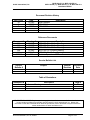
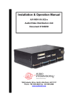
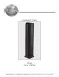
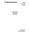
1
Installation Manual
Model #’s: MCD-102-CH (-x)
MCD-102-RU (-x)
MCD-103-CH (-x)
MCD-102-CP-x
MCD-104-01-x
10 Disc CD Player/Changer
Document #540031
7300 Industry Drive, North Little Rock, AR 72117
Phone: 501-955-2929 Fax: 501-955-2988
www.audiointl.com
MCD-102-CH (-x), MCD-102-RU (-x)
MCD-103-CH (-x), MCD-102-CP (-x), & MCD-104-01-x
Installation Manual
Audio International, Inc.
Document Revision History
Rev. Level
IR
A
B
Date
12/1997
5/1998
4/2000
Description
Initial Release
ECN #2214
ECN #4854
Reference Documents
Document #
N/A
N/A
N/A
N/A
N/A
560015
Drawing #
521906
521887
521923
521922
522146
N/A
Description
MCD-102-CH-x Outline Drawing
MCD-102-RU-x Outline Drawing
MCD-103-CH-x Outline Drawing
MCD-102-CP-x Outline Drawing
MCD-104-01-x Outline Drawing
Guide to Operations-MCD
Service Bulletin List
Service
Bulletin #
Subject
Manual
Revision
Revision
Date
Table of Illustrations
Illustration #
1
Description
Reference Drawings
Page #
14
PROPRIETARY NOTICE: Despite any other copyright notice, this document and information disclosed
herein contains confidential, proprietary designs owned by Audio International, Inc. Neither this
document nor the data contained herein shall be reproduced, used or disclosed to anyone without the
written authorization of Audio International, Inc.
Document #540031, Rev. B, 4/2000
Page 2 of 18
MCD-102-CH (-x), MCD-102-RU (-x)
MCD-103-CH (-x), MCD-102-CP (-x), & MCD-104-01-x
Installation Manual
Audio International, Inc.
Table of Contents
Section
Description
1.0
Page
1.1
1.2
1.3
1.4
General Information …………………………………………….
Introduction ………………………………………………………..
Purpose of the Equipment ……………………………………….
Operational Features ……………………………………………..
Optional Equipment ………………………………………………
4
4
4
5
5
2.1
2.2
2.3
Application ………………………………………………………..
Introduction ………………………………………………………..
Data Bus……………………………………………………………
Potentiometer Setting……………………………………………..
5
5
5
5
3.1
3.2
3.3
3.4
3.5
3.6
3.7
3.8
3.9
Installation ………………………………………………………..
Prior to Installation ………………………………………………..
Unpacking and Inspection ……………………………………….
Cautions & Warnings ……………………………………………..
Wiring Requirements ……………………………………………..
Physical Characteristics…………………………………………..
Electrical Characteristics………………………………………….
Mating Connector Information ……………..…………………….
Pinout Assignment Descriptions ………………………………...
Post-Installation Test ……………………………………………..
6
6
6
7
7
8
8
9
10
11
4.1
4.2
Troubleshooting Guide…………………………………………
General Troubleshooting Procedures…………………………...
Troubleshooting Chart…………………………………………….
12
12
13
13
5.2
Specifications ……………………………………………………
Unit Specifications-MCD-102-CH (-x), MCD-102-RU (-x)
MCD-103-CH (-x), MCD-104-01-x………..
Unit Specifications-MCD-102-CP (-x)…………………………...
6.1
6.2
6.3
6.4
6.5
Reference Drawings …………………………………………….
MCD-102-CH (-x)………………………………………………….
MCD-102-RU (-x)………………………………………………….
MCD-103-CH (-x)………………………………………………….
MCD-102-CP (-x)………………………………………………….
MCD-104-01-x……………………………………………………..
14
14
15
16
17
18
2.0
3.0
4.0
5.0
5.1
6.0
Document #540031, Rev. B, 4/2000
Page 3 of 18
13
13
MCD-102-CH (-x), MCD-102-RU (-x)
MCD-103-CH (-x), MCD-102-CP (-x), & MCD-104-01-x
Installation Manual
Audio International, Inc.
MODEL #’s: MCD-102-CH (-x)
MCD-102-RU (-x)
MCD-103-RU (-x)
MCD-102-CP (-x)
MCD-104-01-x
10 Disc CD Player/Changer
1.0
General Information
1.1
Introduction
This manual contains information for the installation of Audio International,
Inc. (AI) 10 Disc CD Player/Changer, Model number MCD-102-CH (-x)
control head, model number MCD-102-RU (-x) remote unit, model number
MCD-103-RU (-x) remote unit, model number MCD-103-RU (-x) remote
unit, and model number MCD-102-CP (-x) control panel. Also included in
this manual is model number MCD-104-01-x. This unit combines the
MCD-102-CH (-x) and the MCD-102-RU (-x) units into one compact
enclosure.
The “-x” suffix included in the model number designates the type of
connector utilized. Refer to Section 3.7 for details. Information contained
within this publication includes physical and electrical characteristics with
additional references needed for installation.
1.2
Purpose of the Equipment
The MCD 10 Disc CD Player/Changer is a high quality CD player/changer
specifically designed to meet the special requirements of aircraft use.
This CD player/changer has the capability of storing up to ten, 5.0 inch CD
discs and can be mounted at various angles in the aircraft. Each CD
player/changer includes a control head and a remote unit where the CD’s
are stored.
Document #540031, Rev. B, 4/2000
Page 4 of 18
Audio International, Inc.
1.3
MCD-102-CH (-x), MCD-102-RU (-x)
MCD-103-CH (-x), MCD-102-CP (-x), & MCD-104-01-x
Installation Manual
Operational Features
Listed below are key features of the MCD units:
q
q
q
q
q
q
q
q
q
q
q
1.4
DO-160C tested
Operates directly from +28 VDC
Compact, lightweight package
Backlit LCD indicator (green) with front panel controls
Optional infrared remote control capability
AI proprietary RS-485 digital data bus compatible
Frequency response of 20 Hz to 20 kHz (+/-1dB)
Adjustable audio output level of 1V to 5V RMS
Standard plating options for front bezel
No cooling requirements
Specially designed to meet aircraft standards
Optional Equipment
The front bezel of the units can be customized to match the interior style
of any aircraft. They can be plated or painted to match any interior.
Stacking units are available from AI to house multiple source equipment
units.
Contact your AI representative for details.
2.0
Application
2.1
Introduction
The MCD 10 Disc CD Changer/Player is a compact disc changer system
comprised of the remote unit and a CD changer. The remote unit
modulates the audio signal from the CD changer into a frequency signal
so that it can be received by the aircraft audio.
2.2
Data Bus
The MCD units are designed to interface with other Audio International
equipment via AI’s proprietary RS-485 serial data bus.
2.3
Potentiometer Settings
Right and left output level adjustments are located on the rear of the unit.
The adjustment potentiometers allow the user to adjust the output
between 1 volt and 5 volts RMS. To increase the level, turn the
potentiometer screw clockwise; to decrease turn the screw
counterclockwise.
Document #540031, Rev. B, 4/2000
Page 5 of 18
Audio International, Inc.
3.0
MCD-102-CH (-x), MCD-102-RU (-x)
MCD-103-CH (-x), MCD-102-CP (-x), & MCD-104-01-x
Installation Manual
Installation
3.1
Prior to Installation
Prior to installation, the following items should be considered:
3.1.1 During the design and layout of the aircraft cabin, careful
consideration of the location of this module is necessary. Some of
the items to be considered include:
• Space
• Available power supply
• Environmental conditions (temperature, humidity, etc.)
• Length of cable runs
3.1.2 The MCD unit shall be installed to conform to the standards
designated by the customer, installing agency, and existing
conditions as to the unit location and type of installation.
3.1.3 Mounting screws are required to secure the unit. Refer to
Section 6.0, Reference Drawings, for mounting hole diameters and
configuration.
3.1.4 The CD control head and CD remote units cannot function properly
if they are more than 15 feet away from each other.
3.2
Unpacking and Inspection
Carefully open the packaging and remove the unit. Verify that all
components have been included in the package per the packing list.
Inspect the unit for damage. Retain the packing materials and packing
list.
If damage has occurred during shipping, a claim must be filed with AI
within 24 hours and a “Return Request Authorization Number” must be
obtained from AI. Refer to the front cover of this manual for address and
telephone number of Audio International. Repackage the unit in its
original packaging materials and return it to AI following instructions given
by the AI representative. If no return is necessary, retain the packing
materials for storage or reshipment if necessary.
Document #540031, Rev. B, 4/2000
Page 6 of 18
Audio International, Inc.
3.3
MCD-102-CH (-x), MCD-102-RU (-x)
MCD-103-CH (-x), MCD-102-CP (-x), & MCD-104-01-x
Installation Manual
Cautions and Warnings
3.3.1 It is important to do a pin-to-pin power and ground check on all
connectors. Ensure that power and ground are applied only where
specified. Damage to the unit may result if power or ground is
applied to the wrong points.
3.3.2 DO NOT connect or disconnect the unit while power is applied.
3.3.3 DO NOT remove any factory-installed screws. Damage to the units
may result and void any warranties.
3.3.4 DO NOT touch the liquid crystal fluid if the LCD case is damaged or
broken. It may be dangerous and cause serious harm. If your
body or clothing come in contact with the fluid, wash immediately
with soap and water.
3.3.4 ESD (Electro Static Discharge) guidelines shall be followed.
3.4
Wiring Requirements
3.4.1 Introduction
The installing agency shall supply and fabricate all external cables
and mating connectors. The length and routing of external cables
must be carefully studied and planned before attempting installation
of the equipment. Allow adequate space for installation of cable
and connectors. Avoid sharp bends and placing cables near
aircraft control cables. Maintain a minimum clearance of three (3)
inches from any control cable.
If wiring is run parallel to
combustible fluid or oxygen lines, maintain a separation of six (6)
inches between the lines.
3.4.2 Power Wires
All power and ground wires shall be 22 AWG (minimum). Power
ground wires shall be grounded within twelve (12) inches of the
unit. All wires shall be in accordance with MIL-W-22759 or
equivalent. Protect power wires with circuit breakers or fuses
located close to the electrical power source bus.
3.4.3 Audio Lines
All audio lines are 24 AWG (minimum) twisted shielded pair with
the cable shields properly grounded. Twisted, shielded cable shall
be in accordance with MIL-W-27500 or equivalent.
Document #540031, Rev. B, 4/2000
Page 7 of 18
Audio International, Inc.
MCD-102-CH (-x), MCD-102-RU (-x)
MCD-103-CH (-x), MCD-102-CP (-x), & MCD-104-01-x
Installation Manual
3.4.4 Data Bus Lines
All data bus connections require twisted shielded cable with the
cable shields properly grounded. Twisted, shielded cable must be
in accordance with MIL-W-27500 or equivalent. The wire size for
the conductors in this cable is to be 22 AWG (minimum). The
shield is to be connected wherever a shield pin is provided. Shield
terminations are to be made as close to the connector pin as
possible. In the event shield pins are not provided, the data bus
shield must be terminated per AI’s proprietary RS-485 specification.
All equipment on the RS-485 data bus shall be connected in a
“daisy-chain” configuration. AI’s proprietary RS-485 serial data bus
specification is available upon request.
3.5
Physical Characteristics
3.5.1 Refer to Section 5.0 for unit dimensions.
3.5.2 Refer to Section 6.0 for attachment points.
3.5.3 When mounting the unit, allow sufficient space for mating
connectors.
3.6
Electrical Characteristics
3.6.1 Refer to Section 5.0 for electrical specifications.
3.6.2 Standard configuration requires no infrared strap pins to be
connected. Each different type of AI source equipment can be
configured to accept one of four different sets of infrared codes. To
change the code settings, connect one of the strap pins to the strap
common (never connect more than one strap pin to the strap
common). Three strap pins are available to allow the infrared
codes to be configured.
3.6.3 The MCD-102-CH control head unit utilizes two 15-pin connectors
for electrical connections. P1 connector provides +28 VDC,
left/right audio output, data bus control, infrared input, and four (4)
strapping pins for alternate configuration of infrared digital
command codes. P2 connects to the changer unit MCD-102-RU.
P2 provides +12 VDC power, control lines 1 through 4, and audio
input.
Maximum wire length between the control head and remote unit is
15 feet.
Document #540031, Rev. B, 4/2000
Page 8 of 18
MCD-102-CH (-x), MCD-102-RU (-x)
MCD-103-CH (-x), MCD-102-CP (-x), & MCD-104-01-x
Installation Manual
Audio International, Inc.
3.6.4 The MCD-102-RU remote unit utilizes one 15-pin connector for
electrical connections. This connector provides +12 VDC power
input, control lines 1 through 4, and audio output. Up to ten 5-inch
CD disc may be placed in the magazine.
3.6.5 The MCD-103-CH control head is identical to the MCD-102-Ch
control head with an additional pigtail connector. This connector is
to be connected to the MCD-102-CP control panel. P3 of this unit
provides IMH, data input, ground, chip enable, clock, VDD power
and switching through the control panel. The maximum wire length
between the CH and CP units is 15 feet.
3.6.6 The MCD-104-01-x has been designed to combine the control head
unit and the remote unit into one enclosure. The unit requires on
15-pin connector for electrical connections. P1 provides +28 VDC
power, ground, left/right audio output, data bus control, infrared
input, and four strapping pins for alternate configuration of the
infrared digital command codes.
3.7
Mating Connector Information
All wiring harnesses to the unit are supplied and fabricated by the
installing agency.
Model #
MCD-102-CH-1
MCD-102-CH-2
Pin #
P1
P2
P1
P2
MCD-102-RU-1 (-3)
MCD-102-RU-2 (-4)
MCD-102-CP-1
MCD-102-CP-2
MCD-103-CH-1
MCD-103-CH-2
P1
P2
P3
P1
P2
P3
MCD-104-01-1
MCD-104-01-2
Document #540031, Rev. B, 4/2000
P1
P1
Connector
RD15M10JV30
RD15F10JVL0
DAMA-15P
D20418-2 Female Screwlock
DAMA-15S
D20419-18 Male Screwlock
RD15M10JV30
DAMA-15P
D20418-2 Female Screwlock
RD9M10JVL0
DEMA-9P
D20418-2 Female Screwlock
RD15M10JV30
RD15F10JVL0
RD9F10JV30
DAMA-15P
D20418-2 Female Screwlock
DAMA-15S
D20419-18 Male Screwlock
DEMA-9S
D20419-21 Male Screwlock
RD15M10JV30
DAMA-15P
D20418-2 Female Screwlock
Mating Connector
RD15F10JVL0
RD15M10JV30
DAMA-15S
DAMA-15P
RD15F10JVL0
DAMA-15S
RD9F10JVL30
DEMA-9S
RD15F10JVL0
RD15M10JV30
RD9M10JVL0
DAMA15S
DAMA-15P
DEMA-9P
RD15F10JVL0
DAMA-15S
Page 9 of 18
MCD-102-CH (-x), MCD-102-RU (-x)
MCD-103-CH (-x), MCD-102-CP (-x), & MCD-104-01-x
Installation Manual
Audio International, Inc.
3.8
Pinout Assignment Descriptions
3.8.1 The MCD-102-CH (-x) pinout is as follows:
Pin #
1
2
3
4
5
6
7
8
9
10
11
12
13
14
15
P1
Description
+28 VDC Power In
Ground
R+ Audio Output
R- Audio Output
L+ Audio Output
L- Audio Output
Data Bus (A)
Data Bus (B)
Infrared Input +
Infrared Input IR Strap 2
IR Strap 3
IR Strap 4
IR Strap Common
Reserved
Pin #
1
2
3
4
5
6
7
8
9
10
11
12
13
14
15
P2
Description
+12 VDC Power Output
Ground
Control 1
Control 1
Control 3
Control 4
Reserved
Reserved
R+ Audio Input
R- Audio Input
L+ Audio Input
L- Audio Input
Reserved
Reserved
Reserved
3.8.2 The MCD-103-CH* (-x) pinout is as follows:
Pin #
1
2
3
4
5
6
7
8
9
10
11
12
13
14
15
P1
Description
+28 VDC Power
Ground
R+ Audio Output
R- Audio Output
L+ Audio Output
L- Audio Output
Data Bus (A)
Data Bus (B)
Infrared Input +
Infrared Input IR Strap 2
IR Strap 3
IR Strap 4
IR Strap Common
Reserved
Pin #
1
2
3
4
5
6
7
8
9
10
11
12
13
14
15
P2
Description
+12 VDC Out
Ground Out
Control 1
Control 2
Control 3
Control 4
Reserved
Reserved
R+ Audio Input
R- Audio Input
L+ Audio Input
L- Audio Input
Reserved
Reserved
Reserved
Pin #
1
2
3
4
5
6
7
8
9
P3
Description
IMH
DATA
Ground
CE
CLK
VDD
Switch
Reserved
Reserved
*The MCD-103-CH (-x) utilizes the MCD-102-RU (-x) remote unit.
3.8.3 The MCD-102-CP (-x) remote control panel pinout is as follows:
Pin #
1
2
3
4
5
6
7
8
9
Document #540031, Rev. B, 4/2000
Description
IMH
Data
Shield (Ground)
CE
CLK
VDD
Switch
Reserved
Reserved
Page 10 of 18
MCD-102-CH (-x), MCD-102-RU (-x)
MCD-103-CH (-x), MCD-102-CP (-x), & MCD-104-01-x
Installation Manual
Audio International, Inc.
3.8.4 The MCD-102-RU (-x) remote unit pinout is as follows:
Pin #
1
2
3
4
5
6
7
8
9
10
11
12
13
14
15
Description
+12 VDC Power Input
Ground Input
Control 1
Control 2
Control 3
Control 4
Reserved
Reserved
R+ Audio Output
R- Audio Output
L+ Audio Output
L- Audio Output
Reserved
Reserved
Reserved
3.8.5 The MCD-104-01-x pinout is as follows:
Pin #
1
2
3
4
5
6
7
8
9
10
11
12
13
14
15
3.9
Description
+28 VDC Power In
Ground
R+ Audio Output
R- Audio Output
L+ Audio Output
L- Audio Output
Data Bus (A)
Data Bus (B)
Infrared Input +
Infrared Input IR Strap 2
IR Strap 3
IR Strap 4
IR Strap Common
Reserved
Post-Installation Test
3.9.1 With the aircraft power “ON”, apply power to the CD control head
and remote units (if applicable). Load the CD remote unit with one
to ten 5-inch CD’s. Press the PL/ST (play/stop) button on the
control head to start playback.
3.9.2 Select a CD with the DISC ADV (disc advance) or DISC REV (disc
reverse) buttons. Select a specific track of the CD and press the
TRACK ADV (track advance) or TRACK REV (track reverse)
buttons. The LCD display will indicate the CD number and track
that has been selected for playback as well as the elapsed time.
3.9.3 Press the PL/ST button on the control head. Press EJECT on the
remote unit. Remove the CD’s from the CD magazine. If there is a
diagnostic error in the CD changer system, the LCD indicator will
Document #540031, Rev. B, 4/2000
Page 11 of 18
MCD-102-CH (-x), MCD-102-RU (-x)
MCD-103-CH (-x), MCD-102-CP (-x), & MCD-104-01-x
Installation Manual
Audio International, Inc.
display several different error codes. Refer to Section 4.0 for a
definition of these error codes.
4.0
Troubleshooting Guide
4.1
General Troubleshooting Procedures
Many problems can be isolated with the following general techniques:
•
•
•
4.2
To verify power to the unit, recheck +28 VDC is applied to the proper
pins on the unit. Use a voltmeter to verify correct level.
Reset by removing power from the unit for at least one minute and
reapply power. Verify the problem still exists.
Recheck all connections to the unit for security. Check all harness
runs for possible pinching. Recheck all pinouts for application
accuracy.
Troubleshooting Chart
Problem
Sound skips
Disc magazine
not lock in
changer
No sound
Poor sound quality
Error code E-01
Error code E-02
Error code E-04
Error code E-99
Document #540031, Rev. B, 4/2000
will
the
Possible Cause
CD remote unit is incorrectly
installed
Solution
Reinstall unit
CD is dirty or defective
CD magazine does not have
proper loading orientation
Clean or replace CD
Remove the disc magazine,
press EJECT and reinsert
magazine until it is locked
securely into place
Verify +28 VDC power is
present
Power has not been
connected
Power to external equipment
is “off”
Verify source equipment is
“on” and operational. Verify
CD remote unit and control
unit are “on”
External equipment
incorrectly connected
Audio controls improperly
adjusted
Disc magazine not inserted in
the CD remote unit
No disc is inserted in the
magazine
CD is dirty or incorrectly
oriented
CD changer cannot be
operated due to difficulties
Verify all connections per unit
instructions
Adjust the volume level
Insert the disc magazine with
CD’s into the CD changer
Remove magazine and insert
a CD
Clean CD, reinsert correctly
Press RESET on the CD
remote unit
Page 12 of 18
MCD-102-CH (-x), MCD-102-RU (-x)
MCD-103-CH (-x), MCD-102-CP (-x), & MCD-104-01-x
Installation Manual
Audio International, Inc.
5.0
Specifications
5.1
Unit Specifications – MCD-102-CH (-x)
MCD-102-RU (-x)
MCD-103-CH (-x)
MCD-104-01-x
Physical Specifications
Housing
Dimensions & Weight
MCD-102-CH (-x) &
MCD-103-CH (-x)
Aluminum
Length 7.89” / 20.04cm
Width w/bezel 7.38” / 18.75cm
Height 2.30” / 5.84cm
Weight 2.06 lbs. / 0.93 kg
Length 7.30” / 18.54cm
Width w/bracket 12.63” / 32.00cm
Height 3.60” / 9.14cm
Weight 5.25 lbs. / 2.38 kg
Length 7.97” / 20.24cm
Width w/bezel 14.00” / 35.56cm
Height 4.22” / 10.72cm
Weight 9.25 lbs. / 4.20 kg
MCD-102-RU (-x)
MCD-104-01-x
Electrical Specifications
Power
Operating Voltage Range
Data Bus Type
Audio Frequency Response
Audio Output
Audio S/N
Dynamic Range
Channel Separation
Infrared Input
5.2
1A Maximum @ +28 VDC
+18 VDC - +30 VDC
AI Proprietary RS-485
20 Hz to 20 kHz
1 V to 5 V RMS (2K-ohms minimum load)
Factory preset at 2 V RMS
93 dB (nominal)
93 dB
85 dB
+5 VDC Digital Logic Level
Unit Specifications – MCD-102-CP (-x)
Physical Specifications
MCD-102-CP (-x)
Length 6.00” / 15.24cm
Width 1.50” / 3.81cm
Depth 0.69” / 1.75cm
Weight 0.33 lbs. / 0.15 kg
Electrical Specifications
Power
Wire Bundle
Document #540031, Rev. B, 4/2000
130 mA @ +10 VDC
12 inches (+/- 1”)
Page 13 of 18
Audio International, Inc.
6.0
MCD-102-CH (-x), MCD-102-RU (-x)
MCD-103-CH (-x), MCD-102-CP (-x), & MCD-104-01-x
Installation Manual
Reference Drawings
6.1
The following diagrams show the MCD-102-CH (-x) control head with unit
dimensions and attachment points. All dimensions are shown in inches.
Document #540031, Rev. B, 4/2000
Page 14 of 18
Audio International, Inc.
6.2
MCD-102-CH (-x), MCD-102-RU (-x)
MCD-103-CH (-x), MCD-102-CP (-x), & MCD-104-01-x
Installation Manual
The following diagrams show the MCD-102-RU (-x) remote unit with unit
dimensions and attachment points. All dimensions are shown in inches.
Document #540031, Rev. B, 4/2000
Page 15 of 18
Audio International, Inc.
6.3
MCD-102-CH (-x), MCD-102-RU (-x)
MCD-103-CH (-x), MCD-102-CP (-x), & MCD-104-01-x
Installation Manual
The following diagrams show the MCD-103-CH (-x) control head unit with
unit dimensions. All dimensions are shown in inches.
Document #540031, Rev. B, 4/2000
Page 16 of 18
Audio International, Inc.
6.4
MCD-102-CH (-x), MCD-102-RU (-x)
MCD-103-CH (-x), MCD-102-CP (-x), & MCD-104-01-x
Installation Manual
The following diagrams show the MCD-102-CP (-x) control head unit with
unit dimensions. All dimensions are shown in inches.
Document #540031, Rev. B, 4/2000
Page 17 of 18
Audio International, Inc.
6.5
MCD-102-CH (-x), MCD-102-RU (-x)
MCD-103-CH (-x), MCD-102-CP (-x), & MCD-104-01-x
Installation Manual
The following diagrams show the MCD-104-01-x unit with dimensions. All
dimensions are shown in inches.
Document #540031, Rev. B, 4/2000
Page 18 of 18