1
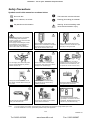
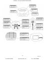
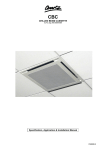
Heronhill - for all your Marstair requirements
ECO Systems
Split Heat Pump Owner’s Manual
Thank you for selecting an ECO heat pump split system.
To ensure many years satisfactory operation, this owner’s manual should be read carefully before
using the heat pump. After reading, store the manual in a safe place and refer to it for questions on
use.
The ECO heat pump is intended for domestic and light commercial applications.
56208001-03
Tel: 01823 665660
www.heronhill.co.uk
Fax: 01823 665807
Heronhill - for all your Marstair requirements
Contents
Safety Precautions
3
Identification of Parts
4
Remote Controller
6
Operating instructions
8
Maintenance
10
Protection
11
Troubleshooting
12
Installation Instructions
13
Preparation before use
Before using the air conditioner, be sure to check and pre-set the following:
•
Remote controller pre-setting
See page 7 to configure to heat pump operation
2 /20
56208001-03
Tel: 01823 665660
www.heronhill.co.uk
Fax: 01823 665807
Heronhill - for all your Marstair requirements
Safety Precautions
Symbols used in this manual are as shown below:
Do not do this.
This instruction must be followed.
This is a feature, not a fault.
Earthing (Grounding) is essential.
Pay attention to this situation.
Warning: Incorrect handling could
cause serious hazard or injury.
Power supply must be in accordance
with the rating plate requirement.
Failure to comply may result in serious
faults, hazards or fire.
If the supply cord is damaged, it must
be replaced by the manufacturer, its
service agent or other qualified
personnel in order to avoid hazards.
Keep the power supply MCB or fuse
clean. Ensure connections to the MCB
or fuse are secure; failure to do so
may result in electric shock or fire.
Don’t use the power supply circuit
breaker to turn the unit off. Don’t pull
the plug out using the cable.
It may prove harmful to your health if
subjected to cool air for long periods. It is
advisable to direct the airflow away from
occupants and cool the room as a whole.
Do not tangle, pull or stress the power
supply cord as damage may result in
electric shock or fire.
Never insert a stick or similar object
into the unit. Such actions may lead to
damage to the unit and injury.
Always turn the air conditioner off via
the remote controller before turning off
the power.
Should repairs become necessary,
they should only be carried out by
qualified personnel.
Ensure the airflow is directed away
from gas burners and stoves.
Do not put any objects on the outdoor
unit or obstruct the airflow.
The equipment must be earthed
(grounded) in accordance with local
regulations. Qualified personnel only
should carry out electrical wiring.
Do not touch the operating buttons
when your hands are wet.
Notes:
1. For the purpose of innovation and improvement, these products are subject to change without prior notice.
2. The air conditioner is not a toy, please keep children away from equipment!
3 /20
56208001-03
Tel: 01823 665660
www.heronhill.co.uk
Fax: 01823 665807
Heronhill - for all your Marstair requirements
Identification of Parts
4 /20
56208001-03
Tel: 01823 665660
www.heronhill.co.uk
Fax: 01823 665807
Heronhill - for all your Marstair requirements
5 /20
56208001-03
Tel: 01823 665660
www.heronhill.co.uk
Fax: 01823 665807
Heronhill - for all your Marstair requirements
Remote Controller
(See page 7 for battery replacement).
6 /20
56208001-03
Tel: 01823 665660
www.heronhill.co.uk
Fax: 01823 665807
Heronhill - for all your Marstair requirements
Remote Controller
How to insert batteries
Remove the battery cover by sliding in the direction of the arrow.
Insert new batteries (2 x AAA) making sure the polarity is correct
The remote controller will default to Heat Pump mode if no buttons
are pressed for 10 seconds, at which point the ‘Heat’/’Cool’ flashing
will stop.
Alternatively:
Press any button on the remote controller while “Heat” is
indicated to preset the controller for Heat Pump operation.
Notes:
If the remote controller is preset for cooling only, heating commands will
not be possible.
Use 2 LR03 AAA (1.5volt) batteries. Do not use rechargeable batteries.
Replace batteries with new ones of the same type when the display
becomes dim.
Re-attach the battery cover by sliding it back into position.
Storage tips for using the Remote Controller
The remote controller may be stored on a wall with a holder.
Using the remote controller
To operate the Eco heat pump, point the controller at
the receiver in the middle of the unit.
The controller will operate up to 7m away from the unit
if pointed directly at the receiver.
7 /20
56208001-03
Tel: 01823 665660
www.heronhill.co.uk
Fax: 01823 665807
Heronhill - for all your Marstair requirements
Operating Instructions
FEEL mode operation procedure
With the remote controller pointing towards the air conditioner:
.
Note:
There will be a delay when changing
mode during unit operation.
The fan may stop during the changeover
•
If you don’t like FEEL mode, try changing to HEATING, DRY or COOLING instead.
8 /20
56208001-03
Tel: 01823 665660
www.heronhill.co.uk
Fax: 01823 665807
Heronhill - for all your Marstair requirements
Operating Instructions
TIMER mode
The timer may be set to start the system operation during your absence, to create comfortable conditions on
your return.
It can also be set to turn the system off after a programmed delay, eg when you go to bed.
Note: After setting the timer, check that the TIMER INDICATION light is visible on the indoor unit.
9 /20
56208001-03
Tel: 01823 665660
www.heronhill.co.uk
Fax: 01823 665807
Heronhill - for all your Marstair requirements
Maintenance
10 /20
56208001-03
Tel: 01823 665660
www.heronhill.co.uk
Fax: 01823 665807
Heronhill - for all your Marstair requirements
Protection
11 /20
56208001-03
Tel: 01823 665660
www.heronhill.co.uk
Fax: 01823 665807
Heronhill - for all your Marstair requirements
Troubleshooting
The following examples may not always be due to a malfunction; please check before calling an
engineer.
12 /20
56208001-03
Tel: 01823 665660
www.heronhill.co.uk
Fax: 01823 665807
Heronhill - for all your Marstair requirements
Installation instructions
Typical installation:
13 /20
56208001-03
Tel: 01823 665660
www.heronhill.co.uk
Fax: 01823 665807
Heronhill - for all your Marstair requirements
Installation instructions
Connecting the cable
Wiring between the indoor and outdoor units.
•
•
•
Remove the PCB cover from the indoor unit;
Refer to the wiring diagram attached to the
indoor unit when connecting the cables to the
indoor unit terminals;
Reinstall the PCB cover. Be sure that side B
is facing towards the outside.
Selecting the best location
Indoor unit location.
•
•
•
•
•
•
•
•
Ensure there is no obstruction to the air outlet
and air can be directed to all areas of the room.
Ensure adequate access for pipe work.
Space between ceilings and walls to be as in
the diagram on page 13.
Ensure the air filter can be easily removed.
Install more than 1m away from electronic
equipment such as televisions.
Keep as far away as possible from
fluorescent light fittings.
Do not obstruct the return air inlet.
Ensure the wall is strong enough to support
the weight of the unit.
Pipe length is
15 metres max
(10 metres for
ECO26)
Outdoor unit location.
•
Install in a well-ventilated area with no obstructions
to the air outlet.
•
Ensure the distance from the rear of the unit to the
wall is as per the diagram on Page 13.
•
Install on a fixed base to prevent excessive vibration.
Pipe length is
15 metres max
(10 metres for
ECO26)
14 /20
56208001-03
Tel: 01823 665660
www.heronhill.co.uk
Fax: 01823 665807
Heronhill - for all your Marstair requirements
Installation instructions
Indoor unit installation
1. Installing the mounting plate
•
•
•
•
•
Determine the location for the indoor unit.
Place the mounting plate against the wall ensuring it is level.
Mark the wall and drill holes to a depth of 32mm.
Insert plastic plugs into the drilled holes and fix the mounting plate with screws.
Ensure the mounting plate is securely fixed then drill a hole through the wall for the pipes.
(Note: The shape of the mounting plate may differ from that shown in the diagram but installation is similar).
2. Drill a hole for the pipes
•
•
•
Determine the position for the pipework
hole according to the location of the
mounting plate.
Drill a hole through the wall ø50-75mm. The hole
should slope down from inside to outside.
Install a sleeve through the hole to protect
both the pipes and the wall.
3. Indoor unit pipework installation
•
Run the pipework through the hole in the wall and connect to the indoor unit.
If the pipework is to enter the indoor unit through the side, cut the unloading piece to suit as in the
diagram below.
•
After connecting the pipework, install and connect the drain hose, then connect the wiring.
When all connections are made, wrap the pipes, cables and drain hose together with thermal
insulation tape.
•
•
15 /20
56208001-03
Tel: 01823 665660
www.heronhill.co.uk
Fax: 01823 665807
Heronhill - for all your Marstair requirements
Installation instructions
NOTE
•
Pipework joints - thermal Insulation:
Insulate the interconnecting pipework
with thermal insulation and tape any joints.
•
Pipework - Thermal Insulation:
a. Run the drain hose under the pipework.
b. Insulate with at least 6mm thick insulation material.
Note: The drain hose is supplied by the installer
•
The drain hose should be installed with
a fall away from the unit.
Ensure there are no kinks in the drain hose
Terminate the drain hose where it cannot
become immersed in water.
Ensure any joints in the drain hose are well
insulated.
•
When the pipework is to be routed to leave
the right hand side of the unit, pipes, drain
hose and cables should be insulated as above
and secured within the unit using the piping
fixer.
•
Pipework connection:
Finger-tighten indoor unit pipework, then use two spanners
as table below.
Pay special attention to the allowable torques (as shown in the table)
to prevent the pipes, connectors and flare nuts from being deformed
and damaged.
Model
Liquid Suction
line
line
Torque (kg/m)
Nut A/F (mm)
Liquid Suction Liquid Suction
line
line
line
line
ECO 26
1/4”
3/8”
1.8
3.5
17
22
ECO 35
1/4”
1/2”
1.8
5.5
17
24
ECO 50
1/4”
1/2”
1.8
5.5
17
24
ECO 70
3/8”
5/8”
3.5
7.5
22
27
16 /20
56208001-03
Tel: 01823 665660
www.heronhill.co.uk
Fax: 01823 665807
Heronhill - for all your Marstair requirements
Installation instructions
4. Connecting the cable
•
Indoor unit
Connect the power cable to the terminals
on the control board on the indoor unit.
Note: For some models it is necessary to remove the
cabinet to connect to the indoor unit terminal.
•
Outdoor unit
1. Remove the access panel. Connect the
cables to the control board terminals.
2. Secure the power cable to the control
board with the cable clamp.
3. Refit the access panel.
Caution:
1. Always provide a dedicated MCB or fuse.
2. Follow the wiring diagram on the inside of the access door.
3. Use the correct cable sizes, as table below.
4. Check all terminations are secure.
5. Use of an earth leakage circuit breaker is recommended.
Cable specifications
Power cable
Interconnecting
power cable
Interconnecting
signal cable
Defrost cable
1.0mm² x 3core #
0.75mm² x 3core
0.75mm² x 2core
---
1.0mm² x 3core #
0.75mm² x 3core
0.75mm² x 2core
---
ECO
50
1.5mm² x 3core #
0.75mm² x 3core
0.75mm² x 2core
0.5mm² x 2core
ECO
70
2.5mm² x 3core **
---
0.75mm² x 6core
0.5mm² x 2core
Model
ECO
26
ECO
35
# Connected to indoor unit.
** Supplied loose – Connect to outdoor unit.
17 /20
56208001-03
Tel: 01823 665660
www.heronhill.co.uk
Fax: 01823 665807
Heronhill - for all your Marstair requirements
Installation instructions
Outdoor unit installation
1.
Install the drain port and drain hose.
Condensate will drain from the outdoor unit
when it operates in heating mode. In order
to protect the environment and prevent
hazardous conditions, install a drain port and
hose to direct the condensate to a suitable drain.
2.
Install and fix the outdoor unit.
Fix with rawlbolts (or similar) to a flat surface
that is strong enough to bear the weight of the
unit. Alternatively use wall mounting brackets (55021100)
3.
Pipework connections.
Remove the valve caps from the 2-way and
3-way valves.
Connect the pipes to the relevant valve and tighten
to the correct torque. See page 16
Evacuation
The system must be evacuated prior to being operated.
18 /20
56208001-03
Tel: 01823 665660
www.heronhill.co.uk
Fax: 01823 665807
Heronhill - for all your Marstair requirements
Installation instructions
How to evacuate the system:1.
Unscrew and remove caps from 2 and 3 – way valves.
2.
Unscrew and remove cap from service port.
3.
Connect vacuum pump flexible hose to the service port.
4.
Start vacuum pump and run until a vacuum of 10mm Hg absolute is reached.
5.
With vacuum pump still running close the low-pressure valve on the gauge manifold. Then stop
the vacuum pump.
6.
Open the 2 – way valve ¼ turn then close it after 10 seconds. Check tightness of all joints using
liquid soap or an electronic leak detector.
7.
Turn 2 and 3 – way valves to the fully open position. Disconnect vacuum pump flexible hose.
8.
Replace and tighten all valve caps.
NOTES
•
Please read this manual before installing and using the ECO heat pump system.
•
Do not let air enter the refrigeration system or discharge refrigerant when moving the equipment.
•
Test run the system after finishing the installation, and record details of its operation.
•
The type of fuse used on the indoor unit controllers is 50T, with rating 3.15A,T, 250V.
•
The system fuse is to be provided by the user according to the current at maximum power input.
Use of an alternative over-current protective device is acceptable.
•
The electrical isolator must be accessible after the installation of the appliance, to allow easy
isolation.
If not possible, connect the supply via a double pole isolator with contact separation of at least
3mm, placed where it is accessible following completion of the installation.
19 /20
56208001-03
Tel: 01823 665660
www.heronhill.co.uk
Fax: 01823 665807
Heronhill - for all your Marstair requirements
TEV LTD, ARMYTAGE ROAD, BRIGHOUSE, WEST YORKSHIRE, HD6 1QF. TEL: + 44 (0) 1484 405600 FAX: +44 (0) 1484 405620
EMAIL: [email protected] WEB: www.marstair.com
20 /20
56208001-03
Tel: 01823 665660
www.heronhill.co.uk
Fax: 01823 665807