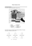
1
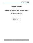
Colour Television
Chassis
LC03E Miravision
AA
Miravision Range
Supplement Manual to LC03E (3122 785 13571)
F_15730_000.eps
300505
Contents
Page
1. Technical Specifications, Connections, and Chassis
Overview
2
2. Safety Instructions, Warnings, and Notes
3
3. Directions for Use
5
4. Mechanical Instructions
6
5. Service Modes, Error Codes, and Fault Finding 10
6. Block Diagrams, Test Point Overviews, and
Waveforms
11
7. Circuit Diagrams and PWB Layouts
11
8. Alignments
11
9. Circuit Descriptions, List of Abbreviations, and IC
Data Sheets
11
10. Spare Parts List
12
11. Revision List
13
©
Copyright 2005 Philips Consumer Electronics B.V. Eindhoven, The Netherlands.
All rights reserved. No part of this publication may be reproduced, stored in a
retrieval system or transmitted, in any form or by any means, electronic,
mechanical, photocopying, or otherwise without the prior permission of Philips.
Published by BB 0566 Service PaCE
Printed in the Netherlands
Subject to modification
EN 3122 785 15730
EN 2
1.
LC03E MV AA
Technical Specifications, Connections, and Chassis Overview
1. Technical Specifications, Connections, and Chassis Overview
Index of this chapter:
1.1 Introduction
1.1
Introduction
The Philips Mirror TV combines an interactive flat LCD TV
together with the reflectivity of a mirror to provide an innovative
2 -in -1 product for the customer.
The Mirror TV comes in several different models:
• 17" Hallway
17HM8801
• 23" Hallway
23HM8801
• 23" Full screen
23HM8821
The Mirror TV product utilizes the existing LCD TV technology
of the Philips 17" and 23" LCD models, and therefore it
provides many of the same features. For familiarity purposes,
the existing Directions For Use (DFU) documentation for the
17" and 23" LCD models can also be used for the Mirror TV.
Some differences may apply, and these differences will be
covered in the enclosed addendum sheet and Installation
Guide (separately available via the ITV organisation).
The MiraVision Installation Guide describes:
• How to replace the decorative frame of the Mirror TV
• How to wall mount the Mirror TV
• Technical specifications of main components
• Connectivity overview
This supplement service manual describes various elements
specific to the Mirror TV application. For common repairs on
the electronics of the LCD panel reference is made to the
service manual LC03E - 3122 785 13571.
ComPair and SearchMan files are available with release 20033 (GB, DE and FR versions).
The information in this document is subject to change.
Accessories are subject to availability.
For further specifications see service manual LC03E
3122 785 13571.
Safety Instructions, Warnings, and Notes
LC03E MV AA
2.
EN 3
2. Safety Instructions, Warnings, and Notes
Index of this chapter:
2.1 Safety Instructions
2.2 Warnings
2.3 Notes
2.1
•
Safety Instructions
Safety regulations require that during a repair:
• Connect the set to the mains via an isolation transformer
(> 800 VA).
• Replace safety components, indicated by the symbol h,
only by components identical to the original ones. Any
other component substitution (other than original type) may
increase risk of fire or electrical shock hazard.
Safety regulations require that after a repair, the set must be
returned in its original condition. Pay in particular attention to
the following points:
• Route the wire trees correctly and fix them with the
mounted cable clamps.
• Check the insulation of the mains lead for external
damage.
• Check the strain relief of the mains cord for proper function.
• Check the electrical DC resistance between the mains plug
and the secondary side (only for sets which have a mains
isolated power supply):
1. Unplug the mains cord and connect a wire between the
two pins of the mains plug.
2. Set the mains switch to the "on" position (keep the
mains cord unplugged!).
3. Measure the resistance value between the pins of the
mains plug and the metal shielding of the tuner or the
aerial connection on the set. The reading should be
between 4.5 Mohm and 12 Mohm.
4. Switch "off" the set, and remove the wire between the
two pins of the mains plug.
• Check the cabinet for defects, to avoid touching of any
inner parts by the customer.
2.2
Warnings
•
•
•
•
All ICs and many other semiconductors are susceptible to
electrostatic discharges (ESD w). Careless handling
during repair can reduce life drastically. Make sure that,
during repair, you are connected with the same potential as
the mass of the set by a wristband with resistance. Keep
components and tools also at this same potential. Available
ESD protection equipment:
– Complete kit ESD3 (small tablemat, wristband,
connection box, extension cable and earth cable) 4822
310 10671.
– Wristband tester 4822 344 13999.
Be careful during measurements in the high voltage
section.
Never replace modules or other components while the unit
is switched "on".
When you align the set, use plastic rather than metal tools.
This will prevent any short circuits and the danger of a
circuit becoming unstable.
2.3
Notes
2.3.1
General
•
Measure the voltages and waveforms with regard to the
chassis (= tuner) ground (H), or hot ground (I), depending
on the tested area of circuitry. The voltages and waveforms
shown in the diagrams are indicative. Measure them in the
Service Default Mode (see chapter 5) with a colour bar
•
•
2.3.2
Schematic Notes
•
•
•
•
•
•
2.3.3
signal and stereo sound (L: 3 kHz, R: 1 kHz unless stated
otherwise) and picture carrier at 475.25 MHz for PAL, or
61.25 MHz for NTSC (channel 3).
Where necessary, measure the waveforms and voltages
with (D) and without (E) aerial signal. Measure the
voltages in the power supply section both in normal
operation (G) and in stand-by (F). These values are
indicated by means of the appropriate symbols.
The semiconductors indicated in the circuit diagram and in
the parts lists, are interchangeable per position with the
semiconductors in the unit, irrespective of the type
indication on these semiconductors.
Manufactured under license from Dolby Laboratories.
“Dolby”, “Pro Logic” and the “double-D symbol”, are
trademarks of Dolby Laboratories.
All resistor values are in ohms and the value multiplier is
often used to indicate the decimal point location (e.g. 2K2
indicates 2.2 kohm).
Resistor values with no multiplier may be indicated with
either an "E" or an "R" (e.g. 220E or 220R indicates 220
ohm).
All capacitor values are given in micro-farads (µ= x10-6),
nano-farads (n= x10-9), or pico-farads (p= x10-12).
Capacitor values may also use the value multiplier as the
decimal point indication (e.g. 2p2 indicates 2.2 pF).
An "asterisk" (*) indicates component usage varies. Refer
to the diversity tables for the correct values.
The correct component values are listed in the Electrical
Replacement Parts List. Therefore, always check this list
when there is any doubt.
Rework on BGA (Ball Grid Array) ICs
General
Although (LF)BGA assembly yields are very high, there may
still be a requirement for component rework. By rework, we
mean the process of removing the component from the PWB
and replacing it with a new component. If an (LF)BGA is
removed from a PWB, the solder balls of the component are
deformed drastically so the removed (LF)BGA has to be
discarded.
Device Removal
As is the case with any component that, it is essential when
removing an (LF)BGA, the board, tracks, solder lands, or
surrounding components are not damaged. To remove an
(LF)BGA, the board must be uniformly heated to a temperature
close to the reflow soldering temperature. A uniform
temperature reduces the chance of warping the PWB.
To do this, we recommend that the board is heated until it is
certain that all the joints are molten. Then carefully pull the
component off the board with a vacuum nozzle. For the
appropriate temperature profiles, see the IC data sheet.
Area Preparation
When the component has been removed, the vacant IC area
must be cleaned before replacing the (LF)BGA.
Removing an IC often leaves varying amounts of solder on the
mounting lands. This excessive solder can be removed with
either a solder sucker or solder wick. The remaining flux can be
removed with a brush and cleaning agent.
After the board is properly cleaned and inspected, apply flux on
the solder lands and on the connection balls of the (LF)BGA.
Note: Do not apply solder paste, as this has shown to result in
problems during re-soldering.
EN 4
2.
LC03E MV AA
Safety Instructions, Warnings, and Notes
be available till the end of the service period. For the repair
of such sets nothing changes.
Device Replacement
The last step in the repair process is to solder the new
component on the board. Ideally, the (LF)BGA should be
aligned under a microscope or magnifying glass. If this is not
possible, try to align the (LF)BGA with any board markers.
So as not to damage neighbouring components, it may be
necessary to reduce some temperatures and times.
In case of doubt whether the board is lead-free or not (or with
mixed technologies), you can use the following method:
• Always use the highest temperature to solder, when using
SAC305 (see also instructions below).
• De-solder thoroughly (clean solder joints to avoid mix of
two alloys).
More Information
For more information on how to handle BGA devices, visit this
URL: http://www.atyourservice.ce.philips.com (needs
subscription). After login, select “Magazine”, then go to
“Workshop Information”. Here you will find Information on how
to deal with BGA-ICs.
2.3.4
Caution: For BGA-ICs, you must use the correct temperatureprofile, which is coupled to the 12NC. For an overview of these
profiles, visit the website www.atyourservice.ce.philips.com
(needs subscription, but is not available for all regions)
You will find this and more technical information within the
"Magazine", chapter "Workshop information".
For additional questions please contact your local repair help
desk.
Lead Free Solder
Philips CE is going to produce lead-free sets (PBF) from
1.1.2005 onwards.
2.3.5
P
Practical Service Precautions
•
b
Figure 2-1 Lead-free logo
This sign normally has a diameter of 6 mm, but if there is less
space on a board also 3 mm is possible.
Regardless of this logo (is not always present), one must treat
all sets from this date onwards according to the following rules.
Due to lead-free technology some rules have to be respected
by the workshop during a repair:
• Use only lead-free soldering tin Philips SAC305 with order
code 0622 149 00106. If lead-free solder paste is required,
please contact the manufacturer of your soldering
equipment. In general, use of solder paste within
workshops should be avoided because paste is not easy to
store and to handle.
• Use only adequate solder tools applicable for lead-free
soldering tin. The solder tool must be able
– To reach at least a solder-tip temperature of 400°C.
– To stabilise the adjusted temperature at the solder-tip.
– To exchange solder-tips for different applications.
• Adjust your solder tool so that a temperature around 360°C
- 380°C is reached and stabilised at the solder joint.
Heating time of the solder-joint should not exceed ~ 4 sec.
Avoid temperatures above 400°C, otherwise wear-out of
tips will rise drastically and flux-fluid will be destroyed. To
avoid wear-out of tips, switch “off” unused equipment or
reduce heat.
• Mix of lead-free soldering tin/parts with leaded soldering
tin/parts is possible but PHILIPS recommends strongly to
avoid mixed regimes. If not to avoid, clean carefully the
solder-joint from old tin and re-solder with new tin.
• Use only original spare-parts listed in the Service-Manuals.
Not listed standard material (commodities) has to be
purchased at external companies.
• Special information for lead-free BGA ICs: these ICs will be
delivered in so-called "dry-packaging" to protect the IC
against moisture. This packaging may only be opened
short before it is used (soldered). Otherwise the body of the
IC gets "wet" inside and during the heating time the
structure of the IC will be destroyed due to high (steam)pressure inside the body. If the packaging was opened
before usage, the IC has to be heated up for some hours
(around 90°C) for drying (think of ESD-protection!).
Do not re-use BGAs at all!
• For sets produced before 1.1.2005, containing leaded
soldering tin and components, all needed spare parts will
•
It makes sense to avoid exposure to electrical shock.
While some sources are expected to have a possible
dangerous impact, others of quite high potential are of
limited current and are sometimes held in less regard.
Always respect voltages. While some may not be
dangerous in themselves, they can cause unexpected
reactions - reactions that are best avoided. Before reaching
into a powered TV set, it is best to test the high voltage
insulation. It is easy to do, and is a good service precaution.
Directions for Use
3. Directions for Use
3.1
Introduction
For familiarity purposes, the existing Directions For Use (DFU)
documentation for the LCD models can also be used for the
Mirror TV.
Some differences may apply, and these differences will be
covered in the Installation Guide (separately available via the
ITV organisation).
You can download the LC4.6E information from the following
websites:
http://www.philips.com/support
http://www.p4c.philips.com
LC03E MV AA
3.
EN 5
EN 6
4.
LC03E MV AA
Mechanical Instructions
4. Mechanical Instructions
Index of this chapter:
4.1 Introduction
4.2 Precautions
4.3 Handling broken mirror glass
4.4 Removing the mirror glass
4.5 Removing Back Cover
4.6 Internal Cabling
4.7 Handling of the Display
4.8 Mounting the Display Back in Place
4.9 How to Replace IR Sensor
4.4
Removing the mirror glass
If it becomes necessary to remove the mirror glass (e.g. due to
damage, or breakage), the screws securing the display (and
the display) must be removed (see section Display Removal).
In the case of the hallway models, there are additional securing
screws (M3x4.5) used to hold the upper mirror in place (i.e. not
just the screws that hold the display in place). These must also
be removed.
Notes:
• Figures below can deviate slightly from the actual situation,
due to the different set executions.
• Follow the disassemble instructions in described order.
4.1
Introduction
The Mirror TV product utilizes the existing LCD TV technology
of the Philips 17" and 23" LCD models, and therefore it
provides many of the same features. For familiarity purposes,
the existing Directions For Use (DFU) documentation for the
17" and 23" LCD models can also be used for the Mirror TV.
Some differences may apply, and these differences will be
covered in the enclosed addendum sheet and Installation
Guide (separately available via the ITV organisation).
• How to replace the decorative frame of the Mirror TV
• How to wall mount the Mirror TV
F_15730_013.eps
270505
Figure 4-1 Mirror glass removal
4.2
Precautions
Before starting to service:
• Place a clean dry soft cloth on the table, to avoid damaging
the frame.
• Only open the mirror TV in a clean environment.
Avoid ingress of dust, particularly on back of mirror.
• Wear gloves to service the set due to extreme sensitivity to
damages of the mirror and frame.
• Do not touch the rear side of the glass with bare hands.
• Due to the special surface used on the rear of the mirror,
surface should only be cleaned with a clean dry cloth (DO
NOT USE any cleaning agents or solvents).
• MiraVision TVs should be received for repair without
customized frames fitted, as Philips cannot be held liable
for any damage done during service to customers' own
frames. Frames are attached to the TV by screws from
behind.
• Packaging: Keep one of each box size at each service
centre (standard Outer packaging). Packaging is available
via Euroservice warehouse (see spare parts list).
4.3
Handling broken mirror glass
When a MiraVision TV is sent to service for replacement of a
broken mirror glass, it is important to follow safety guidelines to
avoid any risk of injury:
• Carefully remove all loose pieces of broken glass.
• Remove display from frame, following guidelines given
above, watch out for loose glass fragments.
• Once display is removed, carefully remove the broken
mirror glass.
• Check for damage to the display. If badly damaged (i.e.
impact on image quality is likely), consider replacement.
• Insert replacement glass, wearing soft gloves to avoid risk
of damage or marks.
Mechanical Instructions
4.5
4.6
Removing Back Cover
Remove back cover, by opening the screws (M4x5) located at
the center back of the cover.
LC03E MV AA
4.
EN 7
Internal Cabling
Disconnect the cables from the LCD display to back cover. Two
cables must be disconnected when removingthe back cover
(speakersa and STBY switch).
F_15730_001.eps
260505
F_15730_004.eps
260505
Figure 4-2
Figure 4-5
4.7
Handling of the Display
Once removed from the mirror TV, the display and LC4.6E
chassis can be accessed and repaired in the normal way (see
LC4.6E service manual). But again, do not remove the display
from the set, unless the fault relates to the LCD panel.
F_15730_002.eps
260505
Figure 4-3
Remove the screws (M4x5) located at the sides of the metal
frame.
F_15730_005.eps
260505
Figure 4-6
Note: The display has a strip of foam attached to it all around
the perimeter of the front face, to allow even contact with the
front part of the mirror TV aluminum frame.
Aluminium Rim of LCD Panel
Shorter
foam
LCD Panel Display Area
F_15730_003.eps
260505
Figure 4-4
Longer foam
F 15730 007.eps
Figure 4-7 Front part
EN 8
4.
LC03E MV AA
Mechanical Instructions
The function of foam is to give some pressure to the glass to
prevent dust penetrating between glass and LCD panel, and to
ensure even contact between glass and frame.
Foam dimensions are 400x10x3 (long side), 227.6x10x3 (short
side) for the 17" panel and 528x10x3 (long side), 305.6x10x3
(short side) for the 23" panel.
4.8
Mounting the Display Back in Place
When placing the display back in position, it is important to
lower it carefully back into place (establish a firm hold on the
display/ chassis), minimising risk of scratching or damaging the
rear surface of the mirror glass.
Care should be taken not to over tighten the screws, in
order to avoid possible deformation of the glass and image
distortion.
Note:
Before returning the defective LCD panel take care for total
removal of the foam. Use a hair dryer to warm the space
between the foam and the frame so that the foam can be torn
off easily. Residual glue can be removed with some alcohol.
4.9
F_15730_009.eps
270505
Figure 4-9
How to Replace IR Sensor
Access of IR sensor is only possible when decorative frame is
removed. Instructions about replacing the decorative frame are
given in chapter 3 of the Mirror TV Installation Guide.
The IR sensor is removed by removing a securing screw
(M3x4.5) at the front of the aluminium frame. The connection
cable passes through the hole provided in the aluminium
frame, allowing full removal and replacement of the IR sensor.
Take care that screws of correct length (self tapping
D3.5x12.5) are used if fitting a customised frame (they
should not penetrate front of the frame). Normally, the
workshop will not receive the set with customized frames fitted.
F_15730_010.eps
270505
Figure 4-10
F_15730_008.eps
270505
Figure 4-8
F_15730_011.eps
270505
Figure 4-11
Mechanical Instructions
F_15730_012.eps
260505
Figure 4-12
LC03E MV AA
4.
EN 9
EN 10
5.
LC03E MV AA
Service Modes, Error Codes, and Fault Finding
5. Service Modes, Error Codes, and Fault Finding
5.1
ICONN Switch
Check the position of the ICONN switch if Mirror TV does not
respond to the Remote control. See also Annex B of the Mirror
TV Installation guide.
Normally signals from the remote control go directly to the
Mirror TV (left side picture). After rerouting the remote control
signals and installing the connectivity box, remote control
commands have to go via the connectivity box to the Mirror TV
(right side picture).
F_15730_014.eps
270505
Figure 5-1
Locate the small hole at the rear side of the Mirror TV as
indicated in the following picture:
F_15730_015.eps
270505
Figure 5-2
Use a paperclip or thin screwdriver to (de)press the switch
located behind the small hole. The switch must be put in
position B to reroute the RC commands.
Now the Mirror TV will only operate with the Connectivity box
connected.
For further service modes, error codes, and fault finding
see service manual LC03E 3122 785 14711
Block Diagrams, Test Point Overviews, and Waveforms
LC03E MV AA
6.
EN 11
6. Block Diagrams, Test Point Overviews, and Waveforms
See service manual LC03E 3122 785 13571
7. Circuit Diagrams and PWB Layouts
See service manual LC03E 3122 785 13571
8. Alignments
See service manual LC03E 3122 785 13571
9. Circuit Descriptions, List of Abbreviations, and IC Data Sheets
See service manual LC03E 3122 785 13571
EN 12
10.
LC03E MV AA
10. Spare Parts List
3139 128 77371 Speaker assy for 23”
DBB298N
3139 128 77381 Speaker assy for 17"
DBC298N
3139 124 01411 Cable tie - ferrite ring
3139 188 69022 Speaker switch assy
3139 188 69032 IR module with wire assy
3139 124 61561 IR lens
3139 124 90111 Mirror TV glass 17HW
3139 124 90121 Mirror TV glass 23HW
3139 124 90131 Mirror TV glass 23FS
3139 123 22111 Foam LCD17 400x10x3
3139 123 22121 Foam LCD17 227.6x10x3
3139 123 22131 Foam LCD23 305.6x10x3
3139 123 22141 Foam LCD23 528x10x3
3139 123 01241 Wooden decorative
frame 17HW
3139 123 01261 Wooden decorative
frame 23HW
3139 123 01251 Wooden decorative
frame 23FS
3139 120 41641 Screws - self tapping
D3.5x12.5
3128 147 14871 Remote Control
3139 126 83101 Packing (outer box with
buffers) 17HW
3139 126 83081 Packing (outer box with
buffers) 23HW
3139 126 83091 Packing (outer box with
buffers) 23FS
Spare Parts List
Revision List
11. Revision List
Manual xxxx xxx xxxx.0
•
First release.
LC03E MV AA
11.
EN 13