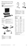
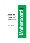
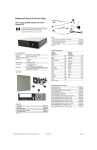
1
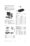
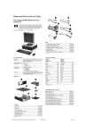
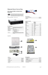
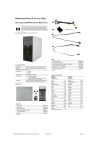
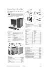
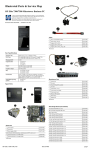
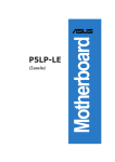
Illustrated Parts & Service Map
HP Compaq dx2400 Microtower Business PC
© 2008 Hewlett-Packard Development Company, L.P. The information contained herein is subject to change without notice. HP shall not be liable for
technical or editorial errors or omissions contained herein. Intel, Celeron,
Core 2 Duo, Core Quad, and the Intel logo are trademarks or registered trademarks of the Intel Corporation and its subsidiaries in the U. S. and other countries.
Document Number 484985-001.
1st Edition March 2008.
Cables
1
Power switch/LED cable assembly
2
SATA cable, 6.5 inch, latch on end
464574-001
448670-001
*
SATA cable, 10 inch, 2 straight ends
392307-001
*
SATA hard drive cable, 4 inch, latch on end
449283-001
*
DMS-59 to dual VGA cable
463023-001
*
Modem cable - see modem cable adapters in Misc Parts section
198220-001
*
Adapter, DVI-I to VGA
202997-001
*
Diskette drive cable
395967-001
*Not shown
Keyboards (not illustrated)
PS/2, Basic
USB, Basic
Key Specifications
435302-xxx
435382-xxx
Arabic
-171
Italian
-061
Intel Core 2 Duo, Pentium Dual-Core 2, Celeron,
Celeron Dual Core
Belgian
-181
LA Spanish
-161
RAM Type
DDR2-SDRAM DIMMs, PC2-6400 (800 MHz) non-ECC
BHCSY
-B41
Norwegian
-091
Maximum RAM Supported
4 GB
Czech
-221
Portuguese
-131
Expansion Slots
•
•
•
Danish
-081
Romanian
-271
Finnish
-351
Russian
-251
French
-051
Slovakian
-231
French Arabic
-DE1
Spanish
-071
Processor Type
1 PCIe-x16
2 PCIe-x1
1 PCI 2.3 (full height)
Graphics Adapter
Intel GMA 3100 integrated
Drive Support
•
•
•
I/O Interfaces
(2) 5.25-inch external bays
(1) 3.5-inch external bay
(2) 3.5-inch internal bays
USB 2.0 (8), RJ-45, audio in (2), audio out, PS/2 ports (2),
VGA
Spare Parts
French Canadian
-121
Swedish
-101
German
-041
Swiss
-111
Greek
-151
Thai
-281
Hebrew
-BB1
Turkish “Q”
-141
Hungarian
-211
U.S.
-001
International
-B31
U.K.
-031
System Unit
1
Front bezel
464575-001
2
Power supply, 300W, PFC
463317-001
2
Power supply, 300W, non-PFC
463318-001
3
Access panel
464597-001
*
3.5-inch bezel blank - diskette drive
459913-001
*
5.25-inch bezel blank
335937-001
* Not shown
DIMM Population
Item
Description
1
DIMM socket XMM1, Channel A (populate first)
Socket Color
Black
2
DIMM socket XMM2, Channel A
Blue
3
DIMM socket XMM3, Channel B (populate second)
Black
4
DIMM socket XMM4, Channel B
Blue
NOTE: A DIMM must occupy the XMM1 socket.
dx2400 Illustrated Parts & Service Map
484985-001
page 1
Standard and Optional Boards (not illustrated)
System board with thermal grease and alcohol pad
462797-001
Memory modules:
512 MB, PC2-6400, CL6
418952-001
1 GB, PC2-6400, CL6
418951-001
2 GB, PC2-6400, CL6
457624-001
Other boards:
Miscellaneous Parts
1
2
Front I/O + USB assembly
448667-001
Chassis fan
449207-001
Belkin 802.11a/g WLAN adapter for use in United States and most of world
391866-002
Belkin 802.11a/g WLAN adapter for use in the rest of the world
391866-001
ATI HD X2400, PCIEx16, DMS-59 and TV outputs, 256MB graphics adapter
462477-001
Adapter, PCI, serial/parallel
321722-001
56K modem, Agere 2006 PCI Hi-Speed, FH
398661-001
445743-001
398333-001
3
Speaker
463316-001
nVidia GeForce 8400 GS 256-MB video card with DMS-59 and TV
(S-Video) outputs, LP
*
Heatsink with fan, alcohol pad, and thermal grease (does not include
backplate)
481422-001
DVI, SDVO graphics card, FH
*
Real-time clock battery
153099-001
HP FireWire IEEE 1394 PCI card, 2 external, 1 internal port, FH
441448-001
Intel Pro 1000 PT Gigabit PCIe NIC, FH
398754-001
*
Rubber foot (4 ea)
370708-001
*
Media card reader, 3.5-inch
407187-001
Intel Celeron Processors with alcohol pad and thermal grease:
*
Media card reader, 3.5-inch, 1394 USB
480032-001
440, 512-KB cache, 2.00 GHz
449166-001
466618-001
430, 512-KB cache, 1.80 GHz
449165-001
420, 512-KB cache, 1.60 GHz
449164-001
*
*
USB powered speakers
Laser mouse
459821-001
*
2-Button, USB, optical with scroll wheel
390938-001
*
2-Button, PS/2, optical with scroll wheel
417966-001
Miscellaneous screw kit, includes:
*
*
*
*
*
*
*
*
*
414180-001
M3 x 5mm hi top, taptite, (8 ea) (247348-001)
#6-32 x 1/4 Hi top, taptite, T15 (14 ea) (192308-001)
#6-32 x 5/16 Hi top, taptite, T15 (4 ea) (192308-002)
#6-32 x 3/16 Hi top, taptite, T15 (6 ea) (192308-003)
Countersunk, flat head plastite (8 ea) (247481-001)
Thumbscrew (2 ea) (368224-002)
#8 x5 /16 plastite, shoulder screw (4 ea) (334248-001)
#6-32 x 1/4 taptite, T15 (12 ea) (101517-067)
Screwlock, external tooth (2 ea) (106902-001)
*
#6-32 x 3/16 taptite, T15 (1 ea) (101517-066)
*
#8 x5 /16 plastite, T15 (1 ea) (334248-002)
*
Intel Celeron Dual-Core Processors with alcohol pad and thermal grease:
E1200, 512-KB cache, 1.60 GHz
468589-001
Intel Core 2 Duo Processors with alcohol pad and thermal grease:
E8500, 6-MB cache, 3.16 GHz
466170-001
E8400, 6-MB cache, 3.00 GHz
466169-001
E8300, 6-MB cache, 2.83 GHz
466168-001
E8200, 6-MB cache, 2.67 GHz
466171-001
E6850, 4-MB cache, 3.00 GHz
450792-001
E6750, 4-MB cache, 2.66 GHz
450791-001
E6550, 4-MB cache, 2.33 GHz
450694-001
E4600, 2-MB cache, 2.40 GHz
462569-001
E4500, 2-MB cache, 2.20 GHz
449452-001
Intel Pentium Dual-Core 2 Processors with alcohol pad and thermal grease:
#6-19 x 1/4 plastite, T15 (1 ea) (101346-067)
Modem Cable Adapters (not illustrated) (use with 198220-001)
Australia
417561-011
Italy
316904-065
Belgium
316904-181
Netherlands
316920-335
Czech
234963-225
Poland/Russia
316904-241
Germany
316904-041
Scandinavia
382848-DH1
Greece
316904-151
South Africa
316904-AR1
France
316904-051
Switzerland
417562-111
Hungary
234963-215
Turkey
316904-141
Israel
316904-BB1
U.K.
158593-035
E2200, 1-MB cache, 2.20-GHz
465216-01
E2180, 1-MB cache, 2.00-GHz
457656-01
E2160, 1-MB cache, 1.80-GHz
457622-001
System Board
*Not shown
Mass Storage Devices (not illustrated)
Diskette drive with bezel
431452-001
16X SATA DVD±RW and CD-RW drive with LightScribe
447310-001
16X SATA DVD-ROM drive
419496-001
48X CD-RW/DVD-ROM combo drive
419497-001
500 GB SATA hard drive
457909-001
250 GB, 7200-RPM SATA hard drive, 8-MB cache
449980-001
160 GB, 7200-RPM SATA hard drive, 8-MB cache
449979-001
80 GB, 7200-RPM SATA hard drive, 8-MB cache
449978-001
Interrupt Assignments
IRQ
System Function
IRQ
System Function
0
Timer Interrupt
18
Intel ICH9 Family USB Universal
Host Controller
1
Keyboard
18
Intel ICH9 Family USB2 Enhanced
Host Controller
System Board Connectors and Jumpers (position of some untitled
components may vary in location)
LAN+USB
RJ-45 over dual USB
F_PANEL
Power button/LED
USB
Double stack USB
SPEAKER
Internal speaker
PCI 1
PCI slot 1
VGA
VGA connector
PCIE_X1_1
PCIe X1, slot 1
CPU_FAN
CPU fan
System fan
8
Real-Time Clock
19
Intel 82801HR/HH/HO SATA RAID
Controller
9
Microsoft ACPI-Compliant System
19
Intel ICH9 Family USB Universal
Host Controller
PCIE_X1_2
PCIe X1, slot 2
SYS_FAN1
PCIE X16
PCIe X16 slot
CMOS+PW
Clear CMOS
KB+MS
Double stack keyboard/mouse
BATTERY
Real-time-clock battery
SATA0 SATA3
Optical drive connectors
DIMM 1 DIMM 4
Memory slots
AUDIO
Double stack audio connector
PROCESSOR
Processor socket
ATXPOWER
Main power
F_USB1
Front USB
FLOPPY
Diskette drive
F_USB2
Media card reader
F_AUDIO
Front audio
ATX_CPU
CPU power
11
Intel ICH9 Family SMBus Controller 20
Intel 82566DC-2 Gigabit Network
Connection
12
Mouse
21
Intel ICH9 Family USB Universal
Host Controller
13
Numeric Data Processor
22
Microsoft UAA Bus Driver for High
Definition Audio
16
Intel G33/G31 Express Chipset Family
23
16
Intel ICH9 Family USB Universal
Host Controller
23
16
Intel ICH9 Family USB Universal
Host Controller
dx2400 Illustrated Parts & Service Map
Intel ICH9 Family USB Universal
Host Controller
Intel ICH9 Family USB2 Enhanced
Host Controller
484985-001
page 2
Setup Utility
POST Audible Codes (continued)
Basic system information is maintained in the Setup Utility held in the system ROM, accessed
by pressing the F10 key when prompted (on screen) during the boot sequence.
Beeps
Meaning
Recommended Action
1 short
No legacy floppy drive or optical drive found.
1. Check cable connections.
2. Run the Computer Setup utility and ensure
the device port is enabled.
2 short
No floppy diskette or CD
found.
1. Check the type of drive that you are using
and use the correct media type.
2. Replace the diskette or CD with a new one.
Computer Setup Menu
Heading
Option / Description
Main
System Time
Allows you to set system time.
System Date
Allows you to set system date.
3 short
Flashing not ready (missing
Upgrade the BIOS to proper version.
utility or BIOS image file, etc.)
Language
Allows you to select the language.
4 short
Floppy Diskette A
Allows you to set to Disabled, 1.44 MB 3.5”, Not Installed.
Flashing operation has failed
(checksum error, corrupted
image, etc.)
1st Drive
2nd drive
3rd Drive
4th Drive
Allow you to: view capacity, transfer mode, SATA speed,
NCQ. Also allows you to run HDD self-test for selected channel: SMART status check, SMART short self test, SMART
extended self test.
1. Verify the correct ROM.
2. Flash the ROM if needed.
3. If an expansion board was recently added,
remove it to see if the problem remains.
4. Clear CMOS.
5. If the message disappears, there may be a
problem with the expansion card. 6. Replace
the system board.
System Information
Allows you to view installed memory, memory banks 1-4,
BIOS revision, core version, model number, product number,
asset tag (press Enter to change).
5 short
BIOS recovery was successful
No action required.
CPU Type
View only.
CPU Speed
View only.
Cache RAM
View only.
Advanced
Power
Boot
Exit
Password Security
Establishing a Setup password using computer setup
1. Turn on or restart the computer. If you are in Windows, click Start > Shut Down > Restart.
Primary Video Allows you to select boot display device when more than 2
Adapter
video options are offered by system: Integrated (Onboard),
PCI, PCI-Ex16, PCI-Ex1.
2. As soon as the computer is turned on, press F10 when the monitor light turns green to enter
Computer Setup. Press Enter to bypass the title screen, if necessary. If you do not press F10
when prompted, a restart will be necessary.
Onboard
Video Memory Size
1 MB, 8 MB.
3. Select Security > Setup Password and follow the instructions on the screen.
DVMT Mode
Select
Allows you to set video memory mode to: Fixed mode,
DVMT mode.
DVMT/Fixed
Memory
Allows you to set video memory size to: 128 MB, 256 MB,
Maximum DVMT (available for DVMT Mode only).
4. Before exiting, click File > Save Changes and Exit.
PS/2 Mouse
Disable/enable/auto detect
USB Legacy
Mode Support
Disable/enable (USB keyboard, mouse, and flash media).
Changing a Power-on or Setup password
1. Turn on or restart the computer. If you are in Windows, click Start > Shut Down > Restart.
2. If you want to change the Setup password, as soon as the computer is turned on, press F10
when the monitor light turns green to enter Computer Setup. Press Enter to bypass the title
screen, if necessary.
3. If you want to change the Power-On password, when the key icon appears, type your current
password, a slash (/) or alternate delimiter character, your new password, another slash (/) or
alternate delimiter character, and your new password again as shown:
Onboard LAN
Disable/enable onboard LAN controller.
Onboard LAN
Boot ROM
Disable/enable the boot ROM of the onboard LAN chip.
SATA1 Controller
Disable/enable the SATA1 controller
SATA1 Controller Mode
If SATA1 controller enabled, allows you to set the mode to
IDE or AHCI.
The new password will take effect the next time the computer is restarted.
SATA2 Controller
Disable/enable the SATA2 controller.
Deleting a Power-on or Setup password
Onboard
Audio
Auto/disable/enable.
Internal
Speaker
Disable/enable.
Supervisor
Password
Allows you to change the supervisor password.
User Password
Allows you to change the user password.
After AC
Power Failure
Allows you to select system restart behavior after power loss:
Stay off, Power on, Auto.
XD
Disable/enable XD bit.
3. Plug in the power cord and turn on the PC.
Boot-time
Diagnostic
Screen
Disable/enable
4. Hold down the F10 key during the boot process and enter BIOS setup to enter any custom
BIOS settings.
1st Boot
Device, 2nd
Boot Device,
3rd Boot
Device, 4th
Boot Device
Allows you to specify which device groups will boot first,
second, third, and fourth or to disable any
of the four: Floppy group, CD-ROM group, Hard drive group,
Network boot group. MS-DOS drive lettering assignments
maybe apply after a non-MS-DOS operating system has
started.
Floppy Group
Boot Priority
Specifies boot device priority within removable devices.
CD-ROM
Boot Priority
Specifies boot device priority within CD/DVD drives.
Hard Drive
Boot Priority
Specifies boot device priority within hard drives.
Network
Group Boot
Priority
Specifies boot device priority within bootable network
devices.
Exit Saving
Changes
Press Enter to exit saving changes.
Exit Discarding Changes
Press Enter to exit discarding changes.
current password/new password/new password.
NOTE: Type the new password carefully since the characters do not appear on the screen.
4. Press Enter.
Load Setup
Defaults
Press Enter to load setup defaults.
Discard
Changes
Press Enter to discard changes.
Save Changes
Press Enter to save changes.
1. Turn on or restart the computer. If you are in Windows, click Start > Shut Down > Restart.
2. To delete the Setup password, as soon as the computer is turned on, press F10 when the
monitor light turns green to enter Computer Setup. Press Enter to bypass the title screen.
3. To delete the Power-on password, when the key icon appears, type the current password
followed by a slash (/) or alternate delimiter character as shown: currentpassword/
4. Press Enter.
Clearing Password using the Jumper
1. Turn off the PC and unplug the the power cord.
2. Move the jumper cap on jumper CLPWD to pins 1-3.
5. After changing or clearing the BIOS passwords, turn off the PC, and then replace the jumper
onto pins 3-5.
HP Insight Diagnostics
The HP Insight Diagnostics utility allows you to view information about the hardware configuration of the computer and perform hardware diagnostic tests on the subsystems of the computer. The utility simplifies the process of effectively identifying, diagnosing, and isolating
hardware issues.
The Survey tab is displayed when you invoke HP Insight Diagnostics. This tab shows the current configuration of the computer. From the Survey tab, there is access to several categories of
information about the computer. Other tabs provide additional information, including diagnostic
test options and test results. The information in each screen of the utility can be saved as an html
file and stored on a diskette or USB HP Drive Key.
Use HP Insight Diagnostics to determine if all the devices installed on the computer are recognized by the system and functioning properly. Running tests is optional but recommended after
installing or connecting a new device. You should run tests, save the test results, and print them
so that you have printed reports available before placing a call to the Customer Support Center.
You can find Insight Diagnostics on the Documentation and Diagnostics CD that shipped with
the computer. You can also download the tool from the HP Web site as follows:
1. Go to www.hp.com
2. Click the Software & Download driver link.
3. Enter the product number (for example, dx2400) in the text box and press the Enter key.
4. Select the specific product.
5. Select the OS.
6. Click the Diagnostics link.
7. Select HP Insight Diagnostics Offline Edition.
8. Select the proper language and click Download.
POST Audible Codes
NOTE: The download includes instructions on how to create a bootable CD.
Beeps
Meaning
Recommended Action
1 short, 1
long
Bad memory or memory configuration error
Check that the memory modules have been
installed correctly and that proper modules are
used.
2 short, 1
long
No graphics card installed or
graphics card initialization
failed.
For systems with a graphics card:
1. Reseat the graphics card. Power on the system.
2. Replace the graphics card.
3. Replace the system board.
For systems with integrated graphics, replace
the system board.
3 short, 1
long
CPU configuration error or
invalid CPU detected before
graphics card initialized.
1. Upgrade the BIOS to proper version.
2. Change the processor.
dx2400 Illustrated Parts & Service Map
Clearing CMOS
1. Turn off the computer and any external devices, and disconnect the power cord from the
power outlet.
2. Remove the access panel.
3. On the system board, move the jumper cap from pins 2-4 (Normal) to pins 4-6 (Clear CMOS)
Keep the cap on pins 4-6 for about 5~10 seconds, and then move the cap back to pins 2-4.
4. Replace the access panel, external devices, reconnect the power cord, and then turn on the
computer.
5. Hold down the Del key during the boot process to enter BIOS setup and re-enter data.
CAUTION: Other than when clearing CMOS, never remove the cap from the default position.
Removing the cap will cause system boot failure.
484985-001
page 3