1
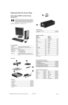
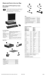
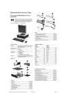
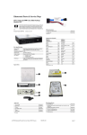
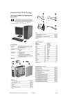
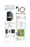
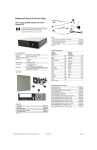
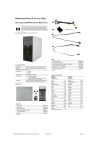
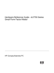
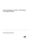
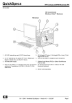
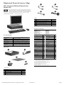
Illustrated Parts & Service Map
HP Compaq dc5700 Small Form Factor
Business PC
© 2006 Hewlett-Packard Development Company, L.P. The information contained herein is subject to change without notice. HP shall not be liable for
technical or editorial errors or omissions contained herein. Intel, Pentium,
Intel Inside, and the Intel logo are trademarks or registered trademarks of the
Intel Corporation and its subsidiaries in the U. S. and other countries.
Document Number 439124-001.
1st Edition September 2006.
Cables
1
SATA HDD cable, 18-in. lg (1 straight, 1 angle end) 393958-001
2
SATA HDD cable, 14-in. lg (2 straight ends)
*
Diskette drive cable
439216-001
3
Power/LED cable with switch and LED holder
432871-001
4
Front I/O with USB and audio cables
432870-001
*
DMS-59 to dual VGA cable adapter
339257-001
391740-001
*Not shown
Keyboards (not illustrated)
PS/2, Basic
PS/2, Basic, 105 key
USB, Basic
USB, Basic, BG1650
USB SmartCard
USB, SmartCard, 105 key
USB, Basic, 105 key
Key Specifications
Processor Type:
-DF1
-171
[8]
Belgian[2]
-181
Korean (Hangul)[4]
[1]
-B41
Arabic[]
Intel Celeron D, Pentium 4 HT, Intel Core 2 Duo, or
Pentium Core 2 Duo
382925-xxx
396215-xxx
382926-xxx
382927-xxx
393670-xxx
396219-xxx
369217-xxx
BHCSY
[1]
Kazakh
AD1
[4]
-161
[8]
-331
LA Spanish
-201
Netherlands
RAM Type:
DDR PC2-5300 non-ECC
Brazilian Portuguese
Maximum RAM Supported:
4 GB
Czech[1]
-221
Norwegian[1]
-091
Expansion Bus:
PCI 2.3 (2), PCI-E x1 (1), and PCI-E x16 for SDVO
graphics (1)
Danish[2]
-081
PRC[1]
-AA1
Graphics Adapter
Integrated controller. SDVO support on PCI-E x16 slot.
[8]
-CA1
Portuguese[1]
-131
Hard drive interface:
SATA 3.0 Gb/s
-351
[7]
-271
I/O Interfaces:
Serial (1 std + 1 optional), parallel (1), USB 2.0 (8), RJ45 (1), front and rear audio jacks (2 each)
-051
Russian[3]
Estonian
Finnish[1]
French[2]
-251
-DE1
Slovakian
-231
-121
Spanish[1]
-071
German[2]
-041
Swedish[2]
-101
Greek[3]
-151
Swiss[2]
-111
French Arabic
Spare Parts
Romanian
French
Canadian[1]
Hebrew
[1]
Hungarian
[8]
[1]
[1]
Icelandic
International
Italian
[2
Japanese[1]
[1]
[1]
-BB1
Taiwanese
-211
[1]
Thai
-281
-DD1
Turkish[1]
-141
[1]
-AB1
-B31
U.S.
-001
-061
Ukranian[9]
-BD1
-291
U.K.[1]
-031
[1]
[1]
not for 382927-xxx, 396215-xxx, 396217-xxx, or 396219-xxx
not for 396215-xxx, 396217-xxx, or 396219-xxx
[3]
not for 382926-xxx, 382927-xxx, 396217-xxx, or 396219-xxx
[4]
not for 382927-xxx, 396217-xxx, or 396219-xxx
[5]
only for 396215-xxx and 296219-xxx
[6] only for 396215-xxx, 396217-xxx, and 382925-xxx
[7] only for 382925-xxx and 382926-xxx
[8]
only for 393670-xxx
[9]
only for 382925-xxx, 382926-xxxan d 396217
[2]
System Unit
1
Chassis
not spared
2
Front bezel assembly
432867-001
3
Access panel
432868-001
4
Power supply, 240W
404796-001
5
5.25-in bezel blank
335937-005
* Not shown
dc5700 Illustrated Parts & Service Map, SFF Chassis
439124-001
page 1
Standard and Optional Boards
Memory modules
1
256 MB, PC2-5300, CL5
396519-001
*
512 MB, PC2-5300, CL5
396520-001
*
1 GB, PC2-5300, CL5
398038-001
System Boards with thermal grease, alcohol pad, and CPU socket cover
2
Standard board
404794-001
*
Board without embedded security (EMEA only)
434369-001
Miscellaneous Parts
Miscellaneous screw kit, includes:
*
#6-32 x .250 hitop screw with serrations
(192308-001)(14 ea)
Intel Celeron D Processors with alcohol pad and thermal grease
414180-001
*
#352, 512K cache, 3.2 GHz, D-0, 533 MHz FSB
433891-001
*
(192308-002) (4 ea)
*
#360, 512K cache, 3.46 GHz, D-0, 533 MHz FSB
434758-001
*
(192308-003) (6 ea)
Intel Pentium 4 HT Processors with alcohol pad and thermal grease
*
(106902-001) (2 ea)
*
#524, 1 MB cache, 3.06 GHz, 533 MHz FSB
412985-001
*
(334248-001) (4 ea)
*
#531, 1 MB cache, 3.0 GHz, 800 MHz FSB
394642-001
*
(247481-001) (8 ea)
*
#541, 1 MB cache, 3.2 GHz, 800 MHz FSB
394812-001
*
(247348-001) (8 ea)
*
(368224-002) (2 ea)
*
(101517-067) (12 ea)
1
Chassis fan
432869-001
2
Heatsink with alcohol pad and factory-applied thermal grease
432873-001
Intel Core 2 Duo Processors with alcohol pad and thermal grease
3
Fan duct
435095-001
*
#E6300, 2x2 MB cache, 1.86 GHz, 1066 FSB
418947-001
4
Rear I/O panel
435527-001
*
#E6400, 2x2 MB cache, 2.13 GHz, 1066 FSB
418948-001
*
Mouse, PS2, scroll type
390937-001
418949-001
*
Mouse, USB, scroll type
390939-001
418950-001
*
Mouse, PS2, optical
417966-001
Other boards
*
Mouse, USB, optical
390938-001
*
Nvidia NVS280 PCI graphics, 64 MB, LP
398686-001
*
Battery, real-time clock
153099-001
*
Nvidia Quadro NVS55, PCI graphics, 64 MB, LP
406412-001
5
Internal speaker
430129-001
Second serial port, LP
432875-001
Tower stand
436533-001
Intel Pentium Core 2 Duo Processors with alcohol pad and thermal
grease
*
*
*
*
#925, 2x2 MB cache, 3.0 GHz, 800 MHz FSB
433510-001
#940, 2x4 MB cache, 3.2 GHz, 800 MHz FSB
430031-001
#945, 2x2 MB cache, 3.4 GHz, 800 MHz FSB
433890-001
#E6600, 2x4 MB cache, 2.4 GHz, 1066 FSB
#E6700, 2x4 MB cache, 2.67 GHz, 1066 FSB
*
DVI-D ADD2 graphics, LP
398333-001
*
*
Intel, Gigabit NIC, LP
398754-001
*
*
Broadcom NIC, PCIE
430654-001
*
Agere International 56K Modem, LP
398661-001
*Not shown
LP = Low profile
FH = Full height
*
DVI-I to VGA graphics adapter
202997-005
* Not shown
LP = Low profile
FH = Full height
Mass Storage Devices (not illustrated)
Diskette drive with bezel and cable
431452-001
Media card reader, 3.5-in
407187-001
Media card reader, 5.25-in
412838-001
52X SATA CD-ROM drive (APJ only)
419469-001
16X SATA DVD-ROM drive
419496-001
48X SATA CD-ROM drive
419635-001
16X SATA DVDRW L drive with LightScribe
419498-001
16x/48x Combo drive
419497-001
80-GB\7200 RPM SATA hard drive, 8MB cache
432392-001
160-GB\7200 RPM SATA hard drive, 8MB cache
432393-001
250-GB\7200 RPM SATA hard drive, 8MB cache
432394-001
dc5700 Illustrated Parts & Service Map, SFF Chassis
439124-001
page 2
System Board
Computer Setup Menu (Continued)
Heading
Option / Description
Storage
(Continued)
Boot Order - Allows you to specify boot order.
Security
Smart Card Options (some models) - Allows you to enable/disable the
Smart Card.
Setup Password - Allows you to set and enable the setup (Administrator)
password.
Power-On Password - Allows you to set and enable power-on password.
Password Options - When any password exists allows you to lock legacy
resources, enable/disable network server mode, specify password
requirement for warm boot, and allows you to enable/disable Setup
Browse Mode.
Embedded Security (some models) - Allows you to enable/disable
Embedded Security and power-on authentication support, reset device to
factory settings, and reset authentication credentials.
Device Security (some models) - Enables/disables all I/O ports, audio,
network controllers, SMBus controller, and embedded security devices.
Network Service Boot - Enables/disables boot from OS on a server.
System IDs - Allows you to set Asset tag, ownership tag, Chassis serial
number, UUID, and keyboard locale setting.
DriveLock Security - Allows you to assign/modify a hard drive password for added security.
OS Security - Allows you to enable/disable Data Execution Prevention
and Intel Virtualization Technology.
System Board Connectors and Jumpers (position of some untitled components
may vary in location)
CR1
5VAUX LED
P60
SATA0
E20
Ambient Temperature
P61
SATA1
E49
Password
P62
SATA2
J20
PCI slot 1
P63
SATA3
J21
PCI slot 2
P70
CPU fan (fansink)
J31
PCIE X1
P8
Primary chassis fan
J41
PCIE X16 for SDVO graphics
only
P9
Chassis fan
P1
Main power
P150
Card reader
P10
Diskette drive
SW50
Clear CMOS
P11
Aux audio
XBT1
Real-time-clock battery
P23
Front audio
XMM1
DIMM 1
P24
Front USB
XMM2
DIMM 2
P3
CPU power
XMM3
DIMM 3
P5
Power button/LED
XMM4
DIMM 4
P52
Flying serial port
XU1
Processor
P6
Internal speaker
Setup Security Level - Allows for limited changes to setup options without password.
Power
OS Power Management - Allows you to enable/disable Runtime Power
Management, ACPI S3 Hard Disk Reset, and ACPI S3 PS2 Mouse
Wakeup. Also Allows you to improve Idle Power Savings and to permit
system to awaken when USB device is inserted.
Hardware Power Management - Allows you to enable/disable SATA bus
power management.
Thermal - Allows you to control minimum permitted fan idle speed.
Advanced Features
Power-On Options - Allows you to set:
• POST mode - QuickBoot, FullBoot, or FullBoot every 1-30 days.
• POST messages - Enable/disable
• F9 prompt - Enable/disable
• F10 prompt - Enable/disable
• F12 prompt - Enable/disable
• Option ROM prompt - Enable/disable
• Remote wakeup boot source - Remote server/local hard drive
• After Power Loss - Off/on/previous state
• POST delay - None, 5, 10, 15, or 20 seconds
• I/O APIC mode - Enable/disable
• Hyperthreading - Enable/disable
• Limit CPUID
Onboard Devices - Allows you to set resources or disable onboard system devices.
PCI Devices - Lists installed PCI devices with their IRQ settings and
allows you to reconfigure IRQ or disable devices.
PCI VGA Configuration - Allows you to specify which VGA controller
will be used when multiple video adapters are available.
System Setup and Boot
Bus Options (some models) - Allows you to enable/disable PCI SERR#
Generation and PCI VGA palette snooping.
Basic system information regarding system information, setup, power management, hardware,
and passwords is maintained in the Setup Utility held in the system ROM. The Setup Utility is
accessed by pressing the F10 key when prompted (on screen) to do so during the boot sequence.
If the screen prompt opportunity is missed, a restart will be necessary.
Device Options - Allows you to set:
• Printer Mode - Bi-Directional, EPP & ECP, Output Only
• Num Lock state at power-on - off/on
• S5 Wake on LAN - enable/disable
• Processor cache - enable/disable
• Unique Sleep State Blink Patterns
• Integrated video - enable/disable
• Internal speakers (some models) enable/disable
• Monitor racking - enable/disable
• NIC PXE Option ROM Download - enable/disable
Computer Setup Menu
Heading
File
Option/Description
System Information - Lists the following main system specifications:
•
•
•
Product name
SKU number (some
models)
Processor type/speed/stepping
Cache Size (L1/L2)
•
•
•
•
•
Memory size/speed/ no. channels
Integrated MAC Address
System BIOS
Chassis serial number
Asset tracking number
System Hardware Interrupts
IRQ
System Function
IRQ
System Function
0
Timer Interrupt
8
Real-Time Clock
About - Displays copyright notice.
1
Keyboard
9
Unused
Set Time and Date - Allows you to set system time and date.
2
Interrupt Controller Cascade
10
Unused, available for PCI
Flash System ROM (some models) - Allows you to select a drive containing a new BIOS.
3
Serial Port (COM B)
11
Unused, available for PCI
4
Serial Port (COM A)
12
Mouse
5
Unused, available for PCI
13
Coprocessor
6
Diskette Drive
14
Primary ATA (IDE) Controller
7
Parallel Port (LPT 1)
15
Secondary ATA (IDE) Controller
•
Replicated Setup - Save to Removable Media and Restore from Removable Media
Default Setup
• Save Current Settings as Default
• Restore Factory Settings as Default
Apply Defaults and Exit - Applies the selected default settings and
clears any established passwords.
Ignore Changes and Exit - Exits Computer setup without applying or
saving any changes.
Save Changes and Exit - Saves changes to system configuration or
default settings and exits Computer Setup.
Storage
Device Configuration - Lists all installed BIOS-controlled storage
devices. The following options are available:
• Diskette Type (Legacy Diskette only) - 3.5” 1.44 MB and 5.25” 1.2
MB
• Drive Emulation of ATAPI Zip drive, hard disk, and ATAPI LS-120
drive
• Multisector Transfers
• Translation Mode
• Translation Parameters
• Default Values IDE/SATA
Storage Options • Removable Media Boot
• Legacy Diskette Write
• BIOS DMA Data Transfers
• SATA Emulation - SATA 0 and 2, SATA 1 and 3, SATA 4 (some
models) SATA 5 (some models(
DPS Self-Test - Allows you to execute self-tests on ATA hard drives.
dc5700 Illustrated Parts & Service Map, SFF Chassis
439124-001
page 3
Error Conditions and Messages
Failsafe Boot Block ROM
The computer comes with a reprogrammable flash system ROM (read only memory). To
upgrade the ROM, download the latest ROM BIOS image from the HP Web site (www.hp.com)
and follow the online GUI/instructions.
Your system ROM includes a Failsafe Boot Block that is protected during the flash process and
allows the computer to be restarted in the unlikely event of an unsuccessful ROM flash.
If the system detects an invalid system ROM during the boot sequence, the Failsafe Boort Block
attempts to locate a valid BIOS image on removable media. To recover from the Boot Block
recovery mode complete the following steps:
Purpose
Floppy drive controller
Prevents the transfer of data to or from the
floppy drive.
Setup Utilities
Device Boot Disabling
Prevents booting from and or all of these
devices: Internal or external USB, Internal
ODD, or Internal FDD
Setup Utilities
Security Option
Prevents use of computer until password is
entered. Can apply to both initial startup and
restart.
Setup Utilities
BIOS Write Protect
Restricts ability to change ROM BIOS without approval.
Setup Utilities.
USB Controller
Allows you to disable or enable all USB
devices.
Setup Utilities
Boot Block Recovery
1. Remove any bootable media from the computer and turn off power.
2. Insert a flash drive or CD containing the ROM BIOS.
3. Turn on power to the system.
4. The system will automatically flash the ROM. After a successful flash, the system will either
automatically restart or prompt the user to unplug the unit, wait 45 seconds, reattach the
power cord, and then press the power button.
How It Is
Established
Feature
Diagnostic LEDs
LED
Color
LED Activity
State/Message
Power
Green
On
Computer on
Power
Green
1 blink every 2 seconds
Normal Suspend Mode
Power
Red
1 blink every second followed
by a 2 second pause
CPU thermal shutdown
Power
Red
3 blinks, 1 blink every second
followed by a 2 second pause
Processor not installed
Power
Red
4 blinks, 1 blink every second
followed by a 2 second pause
Power failure (power supply overload)
4. Before exiting, click File > Save Changes and Exit.
Power
Red
5 blinks, 1 blink every second
followed by a 2 second pause
Pre-video memory error
Establishing a Setup password:
Power
Red
6 blinks, 1 blink every second
followed by a 2 second pause
Pre-video graphics error
1. Turn on or restart the computer. If you are in Windows, click Start > Shut Down >
Restart.
Power
Red
7 blinks, 1 blink every second
followed by a 2 second pause
System board failure (ROM
Power
Red
8 blinks, 1 blink every second
followed by a 2 second pause
Invalid ROM based on Checksum
Power
Red
9 blinks, 1 blink every second
followed by a 2 second pause
System powers on but is unable to boot
Power
Red
10 blinks, 1 blink every second Bad option card
followed by a 2 second pause
none
none
System does not power on and
LEDs are not flashing
Password Security
Establishing a Setup password:
1. Turn on or restart the computer. If you are in Windows, click Start > Shut Down >
Restart.
2. As soon as the computer is turned on, press F10 when the monitor light turns green to enter
Computer Setup. Press Enter to bypass the title screen, if necessary. If you do not press F10
when prompted, a restart will be necessary.
3. Select Security > Setup Password and follow the instructions on the screen.
2. As soon as the computer is turned on, press F10 when the monitor light turns green to enter
Computer Setup. Press Enter to bypass the title screen, if necessary. If you do not press F10
when prompted, a restart will be necessary.
3. Select Security > Power-On Password and follow the instructions on the screen.
Before exiting, click File > Save Changes and Exit.
Changing a password:
1. Turn on or restart the computer. If you are in Windows, click Start> Shut Down > Restart.
To change the Setup password, go to step 2.
To change the Power-on password, go to step 3.
2. To change the Setup password, as soon as the computer is turned on, press F10 when the
monitor light turns green to enter Computer Setup. Press Enter to bypass the title screen, if
necessary.
3. When the key icon appears, type your current password, a slash (/) or alternate de-limiter
character, your new password, another slash (/) or alternate delimiter character, and your new
password again as shown:
Common POST Error Messages
Screen
Message
101-Option
ROM Error
Beeps
Probable Cause
Recommended Action
1L, 1S
1. System ROM checksum
error.
1. Verify ROM, reflash if required
2. Expansion card.
3. Clean CMOS memory, reboot
3. CMOS corruption.
4. Replace system board
current password/new password/new password.
NOTE: Type the new password carefully since the actual characters do not appear on the
screen.
4. Press ENTER.
The new password will take effect the next time the computer is restarted.
System unable to power on
2. Remove suspected card, reboot
4. System board.
103-System
Board
Failure
none
DMA, timers
1. Clear CMOS memory.
164Memory Size
Error
and
201
Memory Error
2S
214-DIMM
Configuration
Warning
none
Populated DIMM configura- Rearrange the DIMMs so that
tion is not optimized
each channel has the same amount
of memory.
301-, 304-Keyboard error
none
Keyboard failure.
Check keyboard connection or
keys. Replace keyboard. If 304,
possible system board problem.
1. Reseat graphics card.
2. Remove expansion board.
3. Replace system board.
Deleting a password
1. Turn on or restart the computer. If you are in Windows, click Start > Shut Down > Restart.
To delete the Setup password, go to step 2.
To delete the Power-On password, go to step 3.
2. To change the Setup password, as soon as the computer is turned on, press F10 when the
monitor light turns green to enter Computer Setup. Press Enter to bypass the title screen, if
necessary.
3. When the key icon appears, type your current password followed by a slash (/) or alternate
delimiter character as shown. Example: currentpassword/
4. Press Enter.
Security Features
Incorrect memory configuration
1. Run Setup (F10).
2. Check DIMMs for proper
seating, type, and HP
compatibility.
3. Remove DIMMs singularly and
reboot to isolate faulty DIMM.
NOTE:
For more information about Setup Utilities refer to the Computer Setup Menu on the previous
page or in the Service Reference Guide.
501-Display
1L, 2S
Adapter Failure
Graphics controller.
Diagnostic Functions
1720-SMART
Hard Drive
Detects Imminent Failure
none
Hard drive is about to fail.
Run drive protection system test if
available. Check for firmware
patch for erroneous error message.
1796-SATA
Cabling Error
none
One or more SATA devices
are improperly attached.
Ensure SATA0 and SATA1 are
used before any other SATA connectors.
1801-Microcode Patch
Error
none
Processor not supported by
ROM BIOS.
1. Upgrade BIOS to proper
version.
Diagnostic functions are provided by the Setup Utility (in system ROM) and by Insight Diagnostics. Insight Diagnostics provides detailed system information including:
•
•
•
•
•
Processor type and speed
Memory amount, mapping, and integrity
Hardware peripheral availability/settings
Hard drive type, space used/available
System identification, asset tracking
Insight Diagnostics may be found on the Documentation and Diagnostics CD that shipped with
the computer. The tool may also be downloaded from the hp Web site using the following procedure:
1. Go to www.hp.com
2. Check monitor connection.
3. Replace graphics card.
2. Change the processor.
NOTES: L = long, S = short
Clearing CMOS
1. Shut down the system and disconnect the power cord from the power outlet.
2. Click the Software and Download driver link.
3. Enter the product number (for example, dc7700) in the text box and press the Enter key.
4. Select the specific product.
2. Remove the chassis access panel.
3. On the system board, press and hold the CMOS button for 5 seconds.
4. Replace the chassis access panel and reconnect the power cord.
5. Select the OS.
5. Turn on the computer and allow it to start.
6. Click the Diagnostics link.
7. Select HP Insight Diagnostics Offline Edition.
8. Select the proper language and click Download.
NOTE: The download includes instructions on how to create a bootable CD. The SoftPaq
number is SP33665 or later.
dc5700 Illustrated Parts & Service Map, SFF Chassis
439124-001
page 4