1
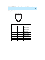
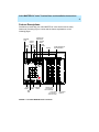
DEFINITY® Enterprise
Communications Server (ECS)
CALLMASTER® IV Voice Terminal
User and Installation Instructions
555-015-171
Comcode 108229717
Issue 2
February 1998
CALLMASTER® IV Voice Terminal User and Installation Instructions
ii
Copyright© 1998, Lucent Technologies
All Rights Reserved
Printed in U.S.A.
Notice
Every effort was made to ensure that the information in this book was
complete and accurate at the time of printing. However, information is subject to
change.
Your Responsibility for Your System’s Security
Toll fraud is the unauthorized use of your telecommunications system by an unauthorized party, for example, persons other than your company’s
employees, agents, subcontractors, or persons working on your company’s behalf.
Note that there may be a risk of toll fraud associated with your
telecommunications system and, if toll fraud occurs, it can result in substantial additional charges for your telecommunications services.
You and your system manager are responsible for the security of your system, such as
programming and configuring your equipment to prevent unauthorized use. The system
manager is also responsible for reading all installation, instruction, and system administration documents provided with this product in order to fully understand the features
that can introduce risk of toll fraud and the steps that can be taken to reduce that risk.
Lucent Technologies does not warrant that this product is immune from or will prevent
unauthorized use of common-carrier telecommunication services or facilities accessed
through or connected to it. Lucent Technologies will not be responsible for any charges
that result from such unauthorized use.
Lucent Technologies Fraud Intervention
If you suspect that you are being victimized by toll fraud and you need technical support
or assistance, call Technical Service Center Toll Fraud Intervention Hotline at 1 800
643-2353.
Interference Warning Information
WARNING: The CALLMASTER® IV voice terminal has been tested and found to comply with the limits for a Class B digital device, pursuant to Part 15 of the FCC Rules and
CISPR-22. These limits are designed to provide reasonable protection against harmful
interference in an installation. This equipment
generates, uses, and can radiate radio-frequency energy and, if not installed and used
in accordance with the instructions, may cause harmful interference to radio and television communications. However, there is no guarantee that interference will not occur in
a particular installation. If this equipment does cause harmful interference to radio or
television reception, which can be
determined by turning the equipment off and on, the user is encouraged to try to correct
the interference by one or more of the following measures:
• Reorient the receiving television or radio antenna where this may be done safely.
CALLMASTER® IV Voice Terminal User and Installation Instructions
iii
• Increase the separation between the telephone equipment.
• Plug the telephone into a different ac outlet than the receiver so that the telephone
equipment and receiver are on different branch circuits.
• Consult the dealer or an experienced radio/tv technician for help.
Trademarks
DEFINITY and CALLMASTER are registered trademarks of Lucent
Technologies.
SoundPoint is a trademark of Polycom, Inc.
Ordering Information
Call:
Lucent Technologies BCS Publications Center
Voice 1 800 457-1235 International Voice 317 322-6791
Fax 1 800 457-1764
International Fax 317 322-6699
Write: Lucent Technologies BCS Publications Center
2855 N. Franklin Road
Indianapolis, IN 46219
Order: Document No. 555-015-171
Comcode 108229717
Issue 2, February 1998
European Union Declaration of Conformity
Lucent Technologies Business Communications Systems declares that the equipment specified in
this document conforms to the referenced European Union (EU) Directives and Harmonized Standards listed below:
EMC Directive
89/336/EEC
Low-Voltage Directive 73/23/EEC
The “CE” mark affixed to the equipment means that it
conforms to the above directives.
Acknowledgment
This document was prepared by Product Publication, Lucent Technologies, Middletown,
NJ
CALLMASTER® IV Voice Terminal User and Installation Instructions
iv
IMPORTANT USER SAFETY
INSTRUCTIONS
The most careful attention has been devoted to quality standards in the
manufacture of your new voice terminal. Safety is a major factor in the design of
every set. But, safety is YOUR responsibility too.
Please read carefully the helpful tips listed below and on the next page. These
suggestions will enable you to take full advantage of your new voice terminal.
Retain these tips for later use.
Use
When using your telephone equipment, the following safety precautions should
always be followed to reduce the risk of fire, electric shock, and injury to persons.
■
Read and understand all instructions.
■
Follow all warnings and instructions marked on the telephone.
■
■
■
■
■
This telephone can be hazardous if immersed in water. To avoid the possibility
of electric shock, do not use it while you are wet. If you accidentally drop the
telephone into water, do not retrieve it until you have first unplugged the line
cord from the modular wall jack. Then, call service personnel to ask about a
replacement.
Avoid using the telephone during electrical storms in your immediate area.
There is a risk of electric shock from lightning. Urgent calls should be brief.
Even though protective measures may have been installed to limit electrical
surges from entering your business, absolute protection from lightning is
impossible.
If you suspect a natural gas leak, report it immediately, but use a telephone
away from the area in question. The telephone’s electrical contacts could
generate a tiny spark. While unlikely, it is possible that this spark could ignite
heavy concentrations of gas.
Never push objects of any kind into the equipment through housing slots since
they may touch hazardous voltage points or short out parts that could result in a
risk of electric shock. Never spill liquid of any kind on the telephone. If liquid is
spilled, however, refer servicing to proper service personnel.
To reduce the risk of electric shock, do not disassemble this telephone. There
are no user serviceable parts. Opening or removing covers may expose you to
hazardous voltages. Incorrect reassembly can cause electric shock when the
telephone is subsequently used.
CALLMASTER® IV Voice Terminal User and Installation Instructions
v
Service
■
■
Before cleaning, unplug the telephone from the modular wall jack. Do not use
liquid cleaners or aerosol cleaners. Use a damp cloth for cleaning.
Unplug the telephone from the modular wall jack. Be sure to refer servicing to
qualified service personnel when these conditions exist:
— If liquid has been spilled into the telephone
— If the telephone has been exposed to rain or water
— If the telephone has been dropped or the housing has been damaged
— If you note a distinct change in the performance of the telephone
SAVE THESE INSTRUCTIONS
!
When you see this warning symbol on the product, refer
to this instructions booklet packed with the product for
more information before proceeding.
CALLMASTER® IV Voice Terminal User and Installation Instructions
vi
CALLMASTER® IV Voice Terminal User and Installation Instructions
vii
ADDITIONAL INSTALLATION WARNING
FAILURE TO FOLLOW THESE INSTRUCTIONS CAN CAUSE DAMAGE TO
THE TERMINAL OR CAUSE THE ASSOCIATED PBX CIRCUIT PACK TO
REMOVE POWER TO THE TERMINAL. IN EITHER CASE THE TERMINAL
WILL NOT FUNCTION CORRECTLY.
The design of this product allows it to operate on either 2-wire or
4-wire DCP circuits. In order for the terminal to function properly in either 2-wire or
4-wire installations, there must be NO INTERCONNECTIONS between the wire
pairs used for 2-wire and
4-wire operation. Bridging or paralleling of these pairs can result in damage to the
terminal or can cause the PBX circuit pack to remove power to the terminal.
REMOVE ALL CONNECTIONS BETWEEN PAIRS BEFORE CONNECTING THE
TERMINAL.
For 2-wire operation, if you need to plug the voice terminal into a
4-pin or 6-pin wall jack, instead of a standard 8-pin modular jack, refer to the
“Modular Wall Jack Wiring” table on the next page to insure that the wires from the
4-pin or 6-pin wall jack are connected to the correct pins on the terminal 2-wire
“LINE” jack.
4-WIRE installations MUST ONLY have PBX connections on pair 2 and pair 3 and,
if necessary, auxiliary power must be connected to pair 4.
2-WIRE installations MUST ONLY have PBX connections on
pair 1 and, if necessary, auxiliary power must be connected to
pair 4.
WHEN THIS PRODUCT IS LOCATED IN A SEPARATE BUILDING from the
telephone communications system, a line current protector MUST be installed at
the entry/exit points of ALL buildings through which the line passes. However, note
that there is a difference between 4-wire and
2-wire installations.
The following are the ONLY acceptable devices for use in a 4-wire installation:
(Note that two protectors are needed at each installation point.)
■
Lucent Technologies 4-type protectors
■
ITW LINX LP-type protectors
For 2-wire installations, the following is recommended: (Only one protector is
needed at each installation point.)
■
Lucent Technologies 4-type protectors
■
ITW LINX LP-type protectors
However, if the above two protectors are not used, the following is acceptable in a
2-wire installation:
■
Lucent Technologies 3BIC (Carbon block) or Lucent 3BEW (gas tube)
protectors
NOTE: The 3BIC and 3BEW protectors can be used ONLY for 2-wire installations.
They CANNOT be used for 4-wire installations.
CALLMASTER® IV Voice Terminal User and Installation Instructions
viii
Wiring Information
12345678
A Voice Terminal Line Jack
MODULAR WALL JACK WIRING
PIN
PAIR
COLOR
DESCRIPTION
1
2
W-O
4-Wire Output
2-Wire (Rec Output)
2
2
O-W
4-Wire Output
2-Wire (Rec Output)
3
3
W-G
4-Wire Input
2-Wire (Not Used)
4
1
W-BL
2-Wire (Tip)
4-Wire (Rec Output)
5
1
BL-W
2-Wire (Ring)
4-Wire (Rec Output)
6
3
G-W
4-Wire Input
2-Wire (Not Used)
7
4
W-BR
Adjunct Power –48 vdc
8
4
BR-W
Adjunct Power Common
For more information about wiring, see the section on “DCP Line Interface” in the next
portion of this booklet.
CALLMASTER® IV Voice Terminal User and Installation Instructions
ix
CALLMASTER® IV Voice Terminal User and Installation Instructions
ix
Contents
Your CALLMASTER IV Voice Terminal . . . . . . . . . . . . . . . . . 1
The Headset (or the Handset) . . . . . . . . . . . . . . . . . . . . . . . 1
The Recorder Interface . . . . . . . . . . . . . . . . . . . . . . . . . . . . 2
Organization of This Guide. . . . . . . . . . . . . . . . . . . . . . . . . . 2
Conventions . . . . . . . . . . . . . . . . . . . . . . . . . . . . . . . . . . . . . 3
Feature Descriptions . . . . . . . . . . . . . . . . . . . . . . . . . . . . . . . 4
Installation . . . . . . . . . . . . . . . . . . . . . . . . . . . . . . . . . . . . . . . 8
Checklist of Parts . . . . . . . . . . . . . . . . . . . . . . . . . . . . . . . . . 8
Orderable Equipment . . . . . . . . . . . . . . . . . . . . . . . . . . . . . . 9
Installation Procedures . . . . . . . . . . . . . . . . . . . . . . . . . . . . 10
Operating Range Requirements. . . . . . . . . . . . . . . . . . . . . 11
The 2-Wire/4-Wire Line Adapter. . . . . . . . . . . . . . . . . . . . . 12
DCP Line Interface . . . . . . . . . . . . . . . . . . . . . . . . . . . . . . . 12
Testing the Headset or Handset . . . . . . . . . . . . . . . . . . . . . 17
Labeling and Installing the Button-Designation
Cards and Covers. . . . . . . . . . . . . . . . . . . . . . . . . . . . . . . 17
Basic Voice Terminal Operations . . . . . . . . . . . . . . . . . . . . 18
Going Off-Hook. . . . . . . . . . . . . . . . . . . . . . . . . . . . . . . . . . 18
Raising or Lowering Receive Volume. . . . . . . . . . . . . . . . . 19
Disconnecting from Calls . . . . . . . . . . . . . . . . . . . . . . . . . . 19
Feature Procedures . . . . . . . . . . . . . . . . . . . . . . . . . . . . . . . 20
Conference . . . . . . . . . . . . . . . . . . . . . . . . . . . . . . . . . . . 20
Drop . . . . . . . . . . . . . . . . . . . . . . . . . . . . . . . . . . . . . . . . . 21
Hold . . . . . . . . . . . . . . . . . . . . . . . . . . . . . . . . . . . . . . . . . 22
Mute . . . . . . . . . . . . . . . . . . . . . . . . . . . . . . . . . . . . . . . . . 22
Select Ring (and Ringer Volume). . . . . . . . . . . . . . . . . . . 23
Self-Test . . . . . . . . . . . . . . . . . . . . . . . . . . . . . . . . . . . . . . 24
Transfer . . . . . . . . . . . . . . . . . . . . . . . . . . . . . . . . . . . . . . 25
CALLMASTER® IV Voice Terminal User and Installation Instructions
x
Technical Description . . . . . . . . . . . . . . . . . . . . . . . . . . . . . 26
Physical Dimensions and Weight. . . . . . . . . . . . . . . . . . . . 26
Power Requirements . . . . . . . . . . . . . . . . . . . . . . . . . . . . . 26
Environmental Requirements. . . . . . . . . . . . . . . . . . . . . . . 26
CALLMASTER® IV Voice Terminal User and Installation Instructions
1
Your CALLMASTER IV Voice Terminal
The CALLMASTER® IV voice terminal referred to in this manual has been
specially designed for use with the Automatic Call Distribution (ACD) system
and the many features of the DEFINITY® Enterprise Communications Server
(ECS) and the DEFINITY® Communications System Generic 1, Generic 2, and
Generic 3.
This voice terminal has six buttons that can be used for either call
appearances or features and 15 buttons that are administered exclusively for
features. It also has a 2-line by 40-character liquid crystal display for showing
call-related information, and designated buttons for both the ACD Log In and
Release features.
In addition, the CALLMASTER IV has a built-in Recorder Interface which
allows you to connect the voice terminal to a recording device so that you can
record all voice interactions.
NOTE: The tape recorder used with the CALLMASTER IV voice terminal must
be purchased by the user; it is not provided with the voice terminal.
For more information on using ACD features, see the DEFINITY Enterprise
Communications Server (ECS) ACD Agent Instructions, 555-204-722; the
DEFINITY Generic 2 and System 85 ACD Agent Instructions, 555-104-713;
the DEFINITY Enterprise Communications Server (ECS) ACD Supervisor
Instructions, 555-230-724; and the DEFINITY Generic 2 and System 85 ACD
Supervisor Instructions, 555-104-714.
The Headset (or the Handset)
Since the CALLMASTER IV voice terminal is most often used with a headset,
each set has two headset jacks, one on each side of the housing, so that one
or two headsets can easily be connected. The voice terminal is immediately
off-hook when the headset is plugged into the voice terminal.
With the use of an optional handset D-Kit, a K2G2 handset can be added to
the voice terminal. (See “Orderable Equipment” in the Installation section of
these instructions for Comcodes of the handset D-Kits and individual parts.)
This kit includes a handset and handset cord, a PJ327 adapter so that the
handset cord can be connected to one of the headset jacks, and a cradle in
which the handset can be kept when it is not in use. (This cradle cannot be
used as a switchhook.)
NOTE: Equipment used with previous versions of the CALLMASTER
voice terminal may not be compatible with the CALLMASTER IV.
NOTE: If you have both a handset and a headset plugged into a
CALLMASTER IV voice terminal, you may want to unplug the handset when
you are not using it, since it can pick up nearby noises (such as papers being
shuffled) which may be heard over the headset.
CALLMASTER® IV Voice Terminal User and Installation Instructions
2
The Recorder Interface
The CALLMASTER IV’s Recorder Interface is designed for recording calls on a
standard tape recorder. (A recorder with AGC [Automatic Gain Control] is
recommended.) With this interface, a warning tone, a soft beep repeated every
15 seconds, notifies the agent and the calling party that the call is being
recorded. Be aware that this tone may be a legal requirement.
IMPORTANT: The use of service observing features and call recording
features may be subject to federal, state, and local laws, rules, or regulations
and may be prohibited pursuant to the laws, rules, or regulations or require
the consent of one or both of the parties to the conversation. Customers
should familiarize themselves with and comply with all applicable laws, rules,
and regulations before using these features.
Organization of This Guide
This user guide is divided into four main sections:
Feature Descriptions — Use the drawing to locate the features on your
CALLMASTER IV voice terminal; use the feature descriptions and
explanations to help you remember how these features are used.
Installation — Use the procedures listed in this section to install your
CALLMASTER IV voice terminal.
Basic Voice Terminal Operations — Use the procedures here to go off-hook,
raise or lower the receive volume, and disconnect from calls.
Feature Procedures — Follow the procedures listed here to use the fixed
features on your voice terminal, those features you can use immediately.
Technical Description — This short section contains the dimensions, power
requirements, and environmental requirements for the CALLMASTER IV voice
terminal.
CALLMASTER® IV Voice Terminal User and Installation Instructions
3
Conventions
The following conventions are used in the procedures:
Each of these boxes represents a button
to which a feature has been assigned. The
button is labeled with a feature name.
Feature
Headset L >>>>>
H
Each of these long rectangular boxes
represents a feature message shown on
the 2-line by 40-character display screen.
CALLMASTER® IV Voice Terminal User and Installation Instructions
4
Feature Descriptions
Familiarize yourself with your CALLMASTER IV voice terminal and its many
features by reviewing Figure 1 below and the feature explanations on the
following pages
.
Conference/
Ring Button
Message
Light
Transfer
Button
Volume
Control
Buttons
Drop/
Select
Button
Test
Button
Hold
Button
Display
6 Call Appearance/
Feature Buttons
CALLMASTER IV
Select
Volume
Conference
Ring
Drop
Test
1
ABC
2
DEF
3
GHI
4
JKL
5
MNO
6
PQRS
7
TUV
8
WXYZ
9
O
#
*
Mute
Mute
Button
Dial
Pad
Log In
Transfer
Hold
Release
Log In Release
Button
Button
Adjunct Jack
(on bottom of
voice terminal)
Line Jacks
(on bottom of
voice terminal)
FIGURE 1 The CALLMASTER IV Voice Terminal
15 Feature
Buttons
CALLMASTER® IV Voice Terminal User and Installation Instructions
5
Starting at the top left of Figure 1 and continuing clockwise:
Message Light — A red light which goes on steadily when a message has
been left for you.
Select Button — Can be used in two different ways:
•
•
Used with
Drop
Test
to initiate a self-test of your voice terminal;
Conference
Ring
Used with
to select your own personalized ring from among eight
available patterns.
Volume Control Buttons — For adjusting the volume of the headset (or
handset). These buttons adjust the volume of the tone ringer if the headset (or
handset) is unplugged or the CALLMASTER IV is ringing.
Drop/Test Button — For disconnecting from a call or dropping the last party
added to a conference call. When used with Select , you can perform a selftest of your voice terminal lights and tone ringer.
Conference/Ring Button — For setting up conference calls. With a
DEFINITY ECS or a DEFINITY Generic 1 or Generic 3, the conference can
include up to six parties. DEFINITY Generic 2 users can conference up to
three parties. (To add more parties, DEFINITY Generic 2 users should see
their system manager.) When used with Select , you can select a
personalized ringing pattern for your voice terminal.
Transfer Button —For transferring a call to another voice terminal.
Hold Button — A red button for putting calls on hold.
Display — A built-in LCD 2-line by 40-character display.
6 Call Appearance/Feature Buttons — These six buttons are devoted to
handling incoming and outgoing calls (call appearances) and are labeled with
an extension number. Each button has a red appearance light beside it to tell
you that this is the line you are using or that this is the line you will get when
you answer a call. The green status light next to each call appearance and
feature button tells you the line or feature is being used.
15 Feature Buttons —Each of these 15 buttons accesses a feature and is
labeled with a feature name. Each button has a green light beside it. When the
green light goes on, the feature is active.
Line Jacks (on bottom of voice terminal) — The two Line jacks are used for
connecting a line cord to your voice terminal.These jacks are labeled “4 WIRE
LINE 2 WIRE.”
Adjunct Jack (on bottom of voice terminal) — This jack is used to connect
compatible adjunct equipment, such as an S101A, S201A, or SoundPoint™
Office Speakerphone, a 507A Adapter, or a 500A1 Headset Adapter, to your
voice terminal. The jack is labeled
.
CALLMASTER® IV Voice Terminal User and Installation Instructions
6
Release Button —Used in ACD operation to end a call. However, pressing
Release is equivalent to hanging up; you will not receive dial tone.
Log in Button — Use this button to automatically log in to the ACD system
when you want to begin answering ACD calls.
Dial Pad — The standard 12-button pad for dialing phone numbers and
accessing features. The letters, “Q” and “Z,” have been added to the
appropriate dial pad keys for directory access, and the “5” button on your dial
pad has raised bars for visually-impaired users.
Mute Button — For turning off the voice transmitter in the headset or handset
so the other person cannot hear you.
CALLMASTER® IV Voice Terminal User and Installation Instructions
7
Headset
Jacks
FIGURE 2 The Headset/Handset Jacks on the Side of the
CALLMASTER IV
On both sides of the CALLMASTER IV voice terminal, there is a set of
headset/handset jacks, as shown in Figure 2 above. Use these jacks for
connecting a headset and/or a handset to your CALLMASTER set.
NOTE: Two headsets plugged into the sides of the CALLMASTER can be
used simultaneously.
If any adjunct is active, the left and right headset jacks on the voice terminal
are deactivated.
CALLMASTER® IV Voice Terminal User and Installation Instructions
8
Installation
NOTE: The CALLMASTER IV voice terminal can only be
desk-mounted; it cannot be wall-mounted.
IMPORTANT: DEFINITY ECS CALLMASTER II, CALLMASTER III, and
CALLMASTER IV Voice Terminals Instructions for Programming the Options,
555-015-172, is a brief set of instructions which includes procedures for
setting the display for 1 or 2 lines and for controlling the Mute button. Within
this booklet, there are also procedures for enabling or disabling the Recorder
Interface and the Recording Warning Tones and for setting the headset and
handset volume. It is important that ONLY a service technician or the system
manager program these options.This document is orderable from the
Publications Center listed at the front of this book.
Checklist of Parts
The CALLMASTER IV voice terminal package includes the following items:
•
•
•
•
A CALLMASTER IV voice terminal with recorder interface
Line cord (7-foot/2.1336 meters, 8-wire D8W87 modular cord)
Button designation cards and plastic covers
This manual that you are presently reading
NOTE: Included in the box with international CALLMASTER voice terminals is
a manual which has pertinent procedural information written in 7 different
languages. This manual is titled The DEFINITY ECS CALLMASTER II,
CALLMASTER III, and CALLMASTER IV International Voice Terminals Quick
Reference. Its Document Ordering number is 555-015-717.
CALLMASTER® IV Voice Terminal User and Installation Instructions
9
Orderable Equipment
The following equipment can be ordered by using the appropriate Comcode or
Price Element Code (PEC):
Orderable Equipment
ITEM
COMCODE
PEC
CALLMASTER IV Voice Terminal (with Recorder Black=108010554
Interface)
Misty Cream=
108010570
White=108010562
3179-10B
3179-10M
3179-10W
Line Cord (7-foot/2.1336 meters, 8-wire D8W87
modular cord)
Line Cord (14-foot/4.2672 meters D8W modular
cord)
31793-03
103786786
103786802
Plug Prong base unit
3122-010-(A)
Handset D-Kit #182083 (black)
Handset cradle*
Thumbscrew*
Handset K2G2*
Handset cord H4DU*
PJ327 Adapter*
105514798
847731114
845952928
407228600
407632819
406978395
31793-22
Handset D-Kit #182084 (misty cream)
Handset cradle*
Thumbscrew*
Handset K2G2*
Handset cord H4DU*
PJ327 Adapter*
105514806
847960226
845952936
407228675
407632827
405730946
31793-03
Handset D-Kit #182835 (white)
Handset cradle*
Thumbscrew*
Handset K2G2*
Handset cord H4DU*
PJ327 Adapter*
107318438
847731106
847278611
407228667
407632835
407128354
31793-04
Designation cards (set of 25) — U.S. English/
Lucent Technologies
Designation cards (set of 25) — U.S. English/
Southwestern Bell
Designation cards (set of 25) — Italian
Designation cards (set of 25) — Japanese
Designation cards (set of 25) — Canadian
French
Designation cards (set of 25) — Dutch
Designation cards (set of 25) — Castilian
Spanish/Latin American Spanish
847933850
31795-CTR15
848055737
31795-SWL01
847945565
847933868
847933884
31795-CTR02
31795-CTR05
31795-CTR07
847933892
847933900
31795-CTR11
31795-CTR16
or -CTR90
* This piece of equipment comes with the Handset D-Kit, but it can also be ordered
separately with the Comcode in the second column.
continued on next page
CALLMASTER® IV Voice Terminal User and Installation Instructions
10
Orderable Equipment (continued)
ITEM
COMCODE
Designation cards (set of 25) — German
847933400
Designation cards (set of 25) — Parisian French/ 847933934
Belgian French
Designation cards (set of 25) — Brazilian
847933959
Portuguese
PEC
31795-CTR92
31795-CTR91
or -CTR39
31795-CTR43
Installation Procedures
Use the following procedures to install your CALLMASTER IV voice terminal.
See Figure 3 for the location of the jacks mentioned below.
1
Lay the voice terminal face down so the bottom slopes toward you.
2
Plug the line cord into the 4-wire LINE jack for 4-wire operation; for 2-wire
operation, plug the line cord into the 2-wire LINE jack. Press firmly until
you hear the line cord click.
NOTE: If you plug the line cord into the wrong LINE jack, be advised that
the voice terminal will not work or it may be damaged.
3
Press the line cord into the line cord routing channel, placing the cord
under the tab, and gently pull any slack from the cord to the rear of the
voice terminal.
4
Turn the voice terminal rightside up so that the display is facing you.
5
Plug the line cord into the modular wall jack. (Since the line cord is 7-feet/
2.1336 meters long, your CALLMASTER voice terminal must be within
this distance from the wall jack.)
NOTE: You may also use a 14-foot/4.2672 meters line cord. To order this cord,
see “Orderable Equipment” earlier in these instructions.
CALLMASTER® IV Voice Terminal User and Installation Instructions
11
Line cord for:
4-wire
2-wire
operation operation
fits here
fits here
Line Cord
Routing
Channel
LINE Jacks
Adjunct Jack
Adjunct Jack
Routing
Channel
FIGURE 3 The LINE Jack, Adjunct Jack, and Routing Channels
Operating Range Requirements
•
•
•
The total distance between the CALLMASTER IV voice terminal with
recorder interface active and the recording device should not exceed 200
feet/60.96 meters.
The distance between the CALLMASTER IV voice terminal and the PBX
must NOT exceed the following:
—
In 4-wire mode, with 22-gauge or 24-gauge wire, the distance
between the CALLMASTER IV and the PBX should not exceed
5,000 feet/1,524 meters; with 26-gauge wire, the distance should
not exceed 4,000 feet/1,219.2 meters.
—
In 2-wire mode, with 22-gauge wire, the distance between the
CALLMASTER IV and the PBX should not exceed
5,500 feet/1,676.4 meters; with 24-gauge wire, the distance should
not exceed 3,500 feet/1,066.8 meters; with
26-gauge wire, the distance should not exceed
2,200 feet/670.56 meters.
The record output impedance is approximately 600 ohms and the output
channel is isolated from the voice terminal with an FCC Part 68-approved
voice transformer.
CALLMASTER® IV Voice Terminal User and Installation Instructions
12
The 2-Wire/4-Wire Line Adapter
The 2-wire/4-wire line adapter (PEC: 32302; Comcode: 407124114 for a single
adapter; PEC: 32303 for a package of 25 adapters) is available to
accommodate situations in which customers need to upgrade from an analogtype RJ11C jack to an 8-wire RJ45X-type jack. This adapter eliminates the
need to remove RJ11C jacks which are presently being used and install new
RJ45X jacks in their place.
Please read the CAUTION statement directly below before beginning the
installation. If all connections are correct, plug the adapter into the RJ11C jack
to provide the proper wiring translation to the DCP terminals.
NOTE: This adapter works ONLY when using a DCP terminal on a
2-wire DCP digital line circuit card (for example, the TN2181 or TN2224). It will
NOT work if you are connecting a DCP terminal to a
4-wire, 4-port, or 4-wire, 8-port DCP line circuit card (such as the TN754B,
TN754, TN413, SN270B, or SN270).
CAUTION: In a previous installation of the premises line jacks,
customers may have wired the jack connections as bridged or in
parallel. These jacks must be rewired, at customer expense, in order for
DCP terminals to function properly in either
2-wire or 4-wire installations. There must be NO INTERCONNECTIONS
between the wire pairs used for 2-wire and 4-wire operations. Bridging
or paralleling of these pairs can result in damage to the terminal or can
cause the PBX line circuit card to remove power to the terminal. All
interconnections between these pairs MUST BE REMOVED BEFORE
the DCP terminals are connected to the jack.
DCP Line Interface
The DCP line interface is a standard D8W 8-wire modular cord. The 8 line-jack
pins are numbered in increasing order from left to right when facing the jack
with the tab slot down. The table on the next page shows pin assignments for
the line cord and jack block interface
.
CALLMASTER® IV Voice Terminal User and Installation Instructions
13
The DCP Line Interface
CONNECTOR BLOCK
DCP JACK INTERFACE
Conn.
Block Pin
Number
D Inside
Wire Color
Pin
Name
Signal Description
3
W-O
1
OD1
Balance output from
telephone (power –48V)
4-wire application
REC-1
Output to Recorder
2-wire application
OD2
Balance output from
telephone (power –48V)
4-wire application
REC-2
Output to Recorder
2-wire application
ID1
Balance input from PBX
(power –48V)
4-wire application
4
O-W
5
W-G
2
3
2-wire — unused
1
W-BL
2
BL-W
6
G-W
4
5
6
REC-1
Output to Recorder
4-wire application
U-T*
Balanced output from
telephone (power –48V)
2-wire application
REC-2
Output to Recorder
4-wire application
U-R*
Balanced output from PBX
(power 0v)
2-wire application
ID2
Balanced input from PBX
(power 0v)
4-wire application
2-wire — unused
7
W-BR
7
P1–
Adjunct power –48V
(to Adjunct jack)
8
BR-W
8
P2+
Adjunct power common
(to Adjunct jack)
* U-T = “Tip”
U-R = “Ring”
CALLMASTER® IV Voice Terminal User and Installation Instructions
14
Figure 4 shows how a CALLMASTER IV, in a 4-wire application with Recorder
Interface, should be configured through the wall jack with the DEFINITY PBX,
an adjunct power source, and the recording device.
Figure 5 shows the same connections when a CALLMASTER IV is in a 2-wire
application.
NOTE: Typically, an RJ45X or equivalent wall jack is used in this type of
configuration.
CALLMASTER® IV Voice Terminal User and Installation Instructions
15
Adjunct Power
Recording
Device
PBX
W-BL (REC1)
BL-W (REC2)
W-O (0D1)
O-W (0D2)
W-G (ID1)
G-W (ID2)
W-BR (P1-)
BR-W (P2+)
Twisted Pair
Wire
White Connecting Block,
110-Type
4-Pair Cross
Connect
Blue Connecting
Block, 110-Type
House Cable
RJ45X Wall
Jack
D8W Cord
CALLMASTER IV
CALLMASTER IV
Voice
Terminal
FIGURE 4 Connecting the 4-Wire CALLMASTER IV with Recorder Interface to
the PBX, Adjunct Power Source, and the Recording Device
CALLMASTER® IV Voice Terminal User and Installation Instructions
16
Adjunct Power
Recording
Device
G-W (Unused)
W-G (Unused)
BL-W (U-R)
W-BL (U-T)
BR-W (P2+)
W-BR (P1-)
O-W (REC2)
W-O (REC1)
PBX
White Connecting Block,
110-Type
4-Pair Cross
Connect
Blue Connecting
Block, 110-Type
House Cable
RJ45X Wall
Jack
D8W Cord
CALLMASTER IV
CALLMASTER IV
Voice
Terminal
FIGURE 5 Connecting the 2-Wire CALLMASTER IV with Recorder Interface to
the PBX, Adjunct Power Source, and the Recording Device
CALLMASTER® IV Voice Terminal User and Installation Instructions
17
Testing the Headset or Handset
NOTE: If you are using a handset, use the installation instructions that come
with the handset kit to install the handset cradle.
1
Plug in the headset or the handset, press a call appearance button, and
listen for dial tone.
•
If you do not hear dial tone, press another call appearance button.
You may also want to check that the cords are connected securely
at both ends.
Labeling and Installing the Button-Designation
Cards and Covers
NOTE: The cards and covers are shipped as loose items with the
CALLMASTER IV voice terminal.
1
Make sure that the voice terminal is right side up.
2
Type or write the numbers/features on the button designation cards with
the appropriate button information.See Figure 6.
3
Crease the perforated edges of the button designation cards and then
remove the cards.
4
If the clear plastic card cover has already been installed on the voice
terminal, remove the cover on the right side of the CALLMASTER IV by
gently lifting the plastic cover, with your fingernail, at the slot on the right
of the set (for the card on the right).
If the plastic card cover has not been previously installed on your
CALLMASTER IV, go on to the next step.
NOTE: If you need to remove the clear card cover on the left side of the set,
gently lift the plastic cover, with your fingernail, at the slot on the left of the set.
CALLMASTER® IV Voice Terminal User and Installation Instructions
18
5
Place the designation card that you have filled out over the buttons, and
then replace the clear cover by gently bending the cover so that the tabs
at the top and bottom end of the cover can be inserted into the
corresponding slots on the housing of the voice terminal. See Figure 6.
Write button
assignment in this
white space under
all assigned buttons
CALLMASTER IV
Designation Card
Lift plastic cover here
Plastic Cover
FIGURE 6 Inserting the Designation Cards
Basic Voice Terminal Operations
The following operations can be used immediately.
Going Off-Hook
NOTE: When the headset or handset is plugged into the terminal, it is
immediately off-hook.
CALLMASTER® IV Voice Terminal User and Installation Instructions
19
Raising or Lowering Receive Volume
You can use the Volume control button to raise and lower the receive level
volume under the following conditions:
•
•
•
•
The CALLMASTER IV voice terminal is off-hook, and the headset(s) is
plugged in.
The voice terminal is not off-hook on an external speakerphone call.
No call is ringing.
You are not in the midst of selecting a personalized ringing pattern.
To raise or lower the receive volume
•
•
To raise the volume of the receive level of the headset or the handset,
.
press the right volume control button labeled
To lower the receive level of the headset or the handset,
.
press the left volume control button labeled
NOTE: There are eight possible volume settings. Each press of the volume
control button raises or lowers the volume one incremental level.
As you raise or lower the headset volume level, the display reflects your
choice, such as:
Headset L >>>>>
H
On the display, one arrow is the lowest setting, and eight arrows is the highest
setting.
NOTE: For procedures to raise and lower the ringer volume on your
CALLMASTER IV set, see the procedures for the Select Ring feature later in
this section.
Disconnecting from Calls
You can disconnect from a call in several ways:
•
•
Press Release to disconnect from any type of call. This method is faster
than waiting for a caller or trunk to disconnect and enables you to perform
other ACD or voice terminal procedures sooner. You do not hear dial tone
after you press Release .
Press Drop
which disconnects you from a call and gives you dial tone.
Test
Use Drop
when you want to disconnect from an ACD or non-ACD call
Test
and place another call.
CALLMASTER® IV Voice Terminal User and Installation Instructions
20
Feature Procedures
The procedures in this section give short, step-by-step instructions for using
each of these features. For your convenience, the features are listed
alphabetically.
CONFERENCE
To add another party to an existing call
NOTE: If your CALLMASTER IV voice terminal is connected to a DEFINITY
ECS or a DEFINITY Generic 1 or Generic 3, the conference call can include up
to six parties. If your CALLMASTER IV is connected to a DEFINITY Generic 2,
the conference can include up to three parties. (For a conference call of more
than three parties, contact your system manager.)
1
Press
•
•
2
•
Present call is put on hold; all other parties remain connected to
each other.
You are given a new call appearance and hear dial tone.
If the party answers, explain who is on the conference call and go on
to Step 3.
If the party does not answer or if the line is busy, press the call
appearance beside the fluttering light to return to the held call (skip
the next step).
Press
•
4
.
Dial the number of the new party and wait for an answer.
•
3
Conference
Ring
Conference
Ring
again.
All parties on the call are now connected.
Repeat Steps 1 through 3 to add another party to the conference call.
CALLMASTER® IV Voice Terminal User and Installation Instructions
21
To add a call you have put on hold to another call to which you are
connected
1
Press
•
•
•
Conference
Ring
.
Green light at the held call appearance continues to flutter.
Green light at the current call appearance also flutters.
You are given a new call appearance and hear dial tone.
2
Press the call appearance button of the held call (first call).
3
Press
•
Conference
Ring
again.
All parties on the call are now connected.
DROP
To disconnect from an active 2-party call
1
Press
•
Drop
Test
.
You hear dial tone.
NOTE: You may press Release instead of Drop
to disconnect faster.
Test
However, if you press Release you will not hear dial tone.
To drop the last party you added to a conference call
1
Press
•
Drop
Test
.
The last party added to the conference call is dropped; you and the
other parties remain connected.
CALLMASTER® IV Voice Terminal User and Installation Instructions
22
HOLD
To put a call on hold while you answer another call, place a call, or
perform some other task
1
Press
•
Hold .
Green light next to the held call appearance flutters.
NOTE: If you put a conference call on hold, the other parties remain
connected.
To answer a new call while active on another call
1
Press
•
2
Hold .
Green light next to the held call appearance flutters.
Press the call appearance of the incoming call.
To return to the held call (dropping the new call)
1
Press the call appearance of the held call.
MUTE
To prevent the other party from hearing you
1
Press
•
2
Mute .
Red light next to
hear you.
Mute
goes on; the other person on the call cannot
When you want to resume the conversation with the other person on the
call, press Mute again.
•
Red light next to button goes off; the other person can hear you
again.
NOTE: The Mute feature has no effect when an adjunct is active. Use the Mute
feature on the adjunct equipment.
CALLMASTER® IV Voice Terminal User and Installation Instructions
23
SELECT RING (AND RINGER VOLUME)
To select a personalized ring
NOTE: There are eight different ringing patterns from which to choose.
1
Press
•
2
Green light next to
Press
•
•
•
Select .
Conference
Ring
Select
goes on steadily.
Select
winks.
.
Green light next to
Current ring pattern plays and repeats every three seconds.
Display shows the pattern you are currently hearing:
Personal Ring #x
(“x” will be a number from 1 to 8.)
Conference
Ring
3
Continue to press
4
When you hear the desired ring pattern, press
•
to cycle through all eight ring patterns.
Your new ring is set; the light next to
Select
Select
again.
goes off.
NOTE: If you receive a call, go off-hook, or lose power during selection, the
process is interrupted and you must start again. If you lose power after you
have selected your personalized ring, you will have to select your ringing
pattern again.
You can raise or lower the volume of the tone ringer under the following
conditions:
•
•
•
•
The CALLMASTER IV is on-hook, and the headset is unplugged.
The voice terminal is off-hook on the external speakerphone.
A call is ringing at the voice terminal.
You are in the process of selecting a personalized ringing pattern for your
voice terminal.
CALLMASTER® IV Voice Terminal User and Installation Instructions
24
To adjust the tone ringer volume if necessary
1
To raise the volume, press the right volume control button labeled
.
lower the volume, press the left volume control button labeled
•
; to
Display shows the volume level:
Ringer L >>>>>
H
(There are eight possible volume settings. On the display, one arrow
indicates the lowest setting has been selected. Eight arrows indicates
the highest setting has been selected.)
SELF-TEST
To test the lights, the ringer, and the display on your voice terminal
1
While on-hook or off-hook, press
•
2
Press and hold down
•
•
•
3
Green light next to
goes on.
.
Three groups of lights go on in sequence.
Ringer sounds.
Display is activated.
Release
•
Select
Drop
Test
Select .
Drop
Test
to end test.
Ringer, display, and lights return to pretest state; the light next to
Select goes off.
CALLMASTER® IV Voice Terminal User and Installation Instructions
25
TRANSFER
To send an existing call to another extension or outside number
1
Press
•
•
•
2
Green light next to the call appearance flutters.
Present call is put on hold.
You are given a new call appearance, and you hear dial tone.
Dial the number where the call will be transferred.
•
•
•
3
Transfer .
You hear ringback tone.
If the call is answered, remain on the line and announce the call if
desired. Continue to Step 3.
If the call is not answered or if the line is busy, return to the held call
by pressing the call appearance button where the green light is
fluttering. Disregard Step 3.
Press
•
Transfer
again.
Call is transferred to the dialed number.
CALLMASTER® IV Voice Terminal User and Installation Instructions
26
Technical Description
Physical Dimensions and Weight
NOTE: The CALLMASTER IV voice terminal can only be
desk-mounted; it cannot be wall-mounted.
The CALLMASTER IV voice terminal measures:
•
•
•
8.5 inches/215.9 millimeters deep
11.0 inches/279.4 millimeters wide
4.25 lbs/1.853 kilograms
Power Requirements
The CALLMASTER IV voice terminal is line powered from the PBX switch. The
CALLMASTER IV will operate in voltage ranges of 42.5 to 56.5 dc volts. See
“Operating Range Requirements” in the Installation section.
NOTE: If adjunct equipment such as an S101A, S201A, or SoundPoint Office
Speakerphone is connected to the CALLMASTER IV voice terminal's Adjunct
jack, it must be auxiliary powered.
Environmental Requirements
The CALLMASTER IV voice terminal can operate in temperatures ranging
from 40 to 120 degrees F (4 to 48 degrees C) and relative humidity ranging
from 5 to 95 percent.
Copyright © 1998 Lucent Technologies
All Rights Reserved