1
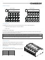
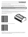
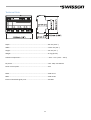
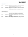
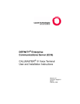
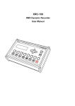
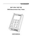
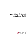
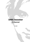
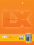
ISP-‐4 Installation Splitter User Manual 2 P:\DINRAIL\ISP-‐4\USERMANUAL\UM-‐ISP-‐D0-‐LEN-‐V00-‐03.DOCX 30. Jan. 2014 Index Index ................................................................................................................................................................................ 3 Introduction ..................................................................................................................................................................... 4 Safety Information ........................................................................................................................................................... 6 Device Overview .............................................................................................................................................................. 7 RDM Protocol (Remote Device Management) ............................................................................................................... 10 Technical Data ................................................................................................................................................................ 11 Ordering Information ..................................................................................................................................................... 12 3 Introduction The DMX splitters of the ISP-‐4 line of products boost an incoming DMX signal and provide it on four output ports. This allows for connecting more than the 32 devices allowed according to ANSI E1.11 to a single universe, as well as for building star topologies. Further more, the ISP-‐4 splitters also act as repeaters and may thus be used for transporting a DMX signal across larger distances. DMX signals often get disturbed by the environment or even by the devices connected to the signal. An ISP-‐4 splitter may completely clear the disturbances if it’s connected at a location where the signal is still “readable”. Providing four individually optically isolated outputs, as well as an optically isolated input, the ISP-‐4 splitters may prevent harmful voltages applied to a given port from affecting the other ports and damaging the connected equipment. The ISP-‐4R variants work within DMX / RDM environments, as well as in pure DMX environments. Therefore, ISP-‐4R splitters are a good solution not only for current RDM users but also for those who expect to use RDM in the future. The ISP-‐4D variants on the other hand only work with DMX, while they ignore any RDM data. ISP-‐4 splitters are Din rail mountable and powered by an external power supply unit (not included). Applications • Boost / repeat DMX signals • Regenerate / clean DMX signals and remove disturbances before they lead to malfunctioning • Prevent reflection issues • Split DMX signals and build star topologies • Connect a large number of fixtures to a single DMX universe • Protect expensive equipment Fields of Application • Architectural Lighting • TV Sets • Theme Parks • Theater • Multimedia Shows • Concert Lighting 4 through data com data off on line termination data data Voltage: 10-48VDC Amp: max 400mA power com Typical Application in DMX Controller Unpacking The ISP Installation Splitter is packaged in a cardboard box. The following items are included: ISP-‐4X-‐DC-‐TERM • The device. • This user manual. • 1 pluggable terminal block connector, 3 pin for connecting the PSU. • 2 pluggable terminal block connectors, 3 pin. • 4 pluggable terminal block connectors, 4 pin. ISP-‐4X-‐DC-‐RJ45X: • The device. • This user manual. • 1 pluggable terminal block connector, 3 pin for connecting the PSU. 5 Safety Information Consider the following notes absolutely when you set up, connect and use the ISP. This product is not for household use. Read this manual before operating the device, follow the safety precautions and observe all warnings in this manual. Use this device only in accordance with local laws and regulations. Safety Precautions • Disconnect the device from AC power before removing any cover or part, including any fuse and when not in use. • Ensure that the device is electrically connected to ground (earth). • Use only a source of AC power that complies with local building and electrical codes and has both overload and ground-‐fault (earth fault) protection. • Before using the device, check that the power distribution equipment and cables are in perfect condition and rated for the current required of all connected devices. • Isolate the device from power immediately if the power cable or the power plug is in any way damaged, defective or wet, or if they show signs of overheating. • Do not expose the device to rain or moisture. • Do not operate the device if any cover or component is missing, damaged or deformed. • Refer any service operation not described is this manual to Swisson. • Provide unrestricted airflow around the device. • Do not operate the device if the ambient temperature exceeds 55°C (131°F). • Do not modify the device in any way not described in this manual or install other than genuine Swisson parts. • Do not attempt to bypass any fuse. Replace any defective fuse with one of the specified type and rating only. • When suspending the device, ensure that the supporting structure and all hardware used can hold at least 10 times the weight of all devices suspended from them. • When suspending the device, install a secondary attachment such as a safety cable that is approved by an official body such as TÜV as a safety attachment for the total weight it secures. The safety cable must comply with EN 60598-‐2-‐17 Section 17.6.6 and be capable of bearing a static suspended load 10 times the weight of the device. • Make sure that any external cover and rigging hardware is securely fastened. • Block access below the work area whenever installing, servicing or moving an overhead device. • Do not use the device in areas where it is exposed to direct sunlight. 6 Device Overview through 4 data data off on line termination power data data Voltage: 10 - 48VDC Amp: max 400mA 3 com 2 com 1 in 5 6 7 8 9 10 11 11 11 11 1. Power input. 2. Line termination switch to turn the line termination on and off. 3. DMX trough-‐port. 4. DMX input. 5. Power LED. 6. Signal LED. Indicates that a signal is being received. 7. Error LED. Indicates a faulty signal. 8. Identify LED. (ISP-‐4R only). 9. Send DMX / RDM LED. Indicates that RDM or DMX data is being sent. (ISP-‐4R only). 10. Receive RDM LED. Indicates that an RDM response is being received and sent back to the controller. (ISP-‐4R only). 11. DMX output port. 7 ISP Block Diagram ISP-‐4D models: PSU ISP-‐4R models: PSU Control Logic Control Logic Optical Isolation Optical Isolation Optical Isolation Optical Isolation Optical Isolation Optical Isolation Optical Isolation Optical Isolation Optical Isolation Optical Isolation Receiver Transmitter Transmitter Transmitter Transmitter Receiver Transmitter Transmitter Transmitter Transmitter Protection Line Termination Protection Protection Protection Protection Protection Line Termination Protection Protection Protection Protection In Port In Port Out Port 1 Out Port 2 Out Port 3 Out Port 4 In Port In Port Out Port 1 Out Port 2 Out Port 3 Out Port 4 PSU Connection A suitable power supply unit that meets the following conditions, must be supplied by the user: • Stabilized DC output voltage: 10V – 48V, max. 400 mA • Power: 4 W See page 7, item 1, “power input”. It is not strictly required but highly recommended to properly connect the ground pin to earth. Not connecting the ground pin may affect the performance of the device. The device can only be operated as a “ground referenced” transmitter if it is properly grounded. See page 9. Warning! For protection from dangerous electric shocks, the device must be grounded (earthed). The local AC power source must have both overload and ground-‐fault (earth fault) protection. DMX Connections The DMX input is fully isolated and has a built in termination. Depending on the product variant, the DMX inputs and the DMX outputs are provided as pluggable screw terminals or as RJ-‐45 connectors. Models with Terminal Connectors This configuration applies to ISP-‐4D-‐TERM and ISP-‐4R-‐TERM. Pin 1 2 3 4 (outputs only) Connection Data + Data -‐ Com Earth 8 The DMX standard ANSI E1.11 suggests that transmitters are “ground referenced”. With the ISP-‐4, this is achieved for each output port by wiring pin 3 to pin 4. In some cases, however, the above configuration may lead to so called ground loops. This applies when a DMX receiver’s COM input signal is connected to the earth with a low resistance. In such cases it may resolve issues by not connecting pin 3 to pin 4 of the corresponding output. Note: Only with the latter setup, each output port is individually optically isolated, meaning that it is totally isolated from the other output ports and from the input section. Models with RJ45 Connectors The RJ45 versions ISP-‐4D-‐DC-‐RJ45A, ISP-‐4R-‐DC-‐RJ45A, ISP-‐4D-‐DC-‐RJ45B and ISP-‐4R-‐DC-‐RJ45B are configured as “isolated” transmitters as defined in ANSI E1.11, such that each output port is individually optically isolated, meaning that it is totally isolated from the other output ports and from the input section. ANSIE1.11 compliant RJ45 configuration, applies to ISP4X-‐DC-‐RJ45A models. Pin 1 2 3 4 5 6 7 8 Shield Connection Data + Data -‐ Not connected Not connected Not connected Not connected Com Com Earth Alternative RJ45 configuration, applies to ISP-‐4X-‐RJ45B models. Pin 1 2 3 4 5 6 7 8 Shield Connection Data -‐ Data + Com Not connected Not connected Not connected Not connected Not connected Earth Line Termination The line termination of the ISP-‐4 splitters may be turned on or off using the toggle button next to the through port. See page 7. The line termination should be turned on by pushing it down when no receiver is connected to the through port of an ISP-‐4, and turned off otherwise. 9 A missing termination at the end of a DMX chain may lead to significant reflection issues. Additional termination resistors in the middle of a chain may cause an unwanted drop of the signal level. Line termination is also known to reduce the susceptibility to environmental noise. RDM Protocol (Remote Device Management) All ISP-‐4R models support the RDM protocol. ISP-‐4D models do not support the RDM protocol. The ISP-‐4R models forward incoming RDM messages to all connected devices and send the RDM responses back to the RDM controller. The ISP-‐4R acts as a non-‐proxy inline device. Further, the ISP-‐4R is a responder itself. It responds to RDM messages and can be discovered on an RDM network. 10 Technical Data Depth ........................................................................................... 90 mm (3.54 “) Width ........................................................................................... 124.5 mm (4.9 “) Height ........................................................................................... 56 mm (2.2 “) Weight .......................................................................................... 0.4 kg (0.9 lb.) Ambient temperature .................................................................. -‐30°C – 55°C (-‐22°F – 131°F) DC power ...................................................................................... 10V -‐ 48V, max 400mA Power consumption ..................................................................... 4W DMX ............................................................................................. ANSI E1.11 RDM ............................................................................................. ANSI E1.20 Electrical standard signal ports .................................................... EIA-‐485 11 Ordering Information DMX-‐512 Variants 20 10 10 ISP-‐4D-‐DC-‐TERM DMX splitter for DIN rail installation. 1 in, 4 out ports. Input and outputs optically isolated. Pluggable screw terminals. 10 – 48V DC. 20 10 15 ISP-‐4D-‐DC-‐RJ45A DMX splitter for DIN rail installation. 1 in, 4 out ports. Input and outputs optically isolated. RJ-‐45, pin configuration according to ANSI E1.11. 10-‐48V DC. 20 10 16 ISP-‐4D-‐DC-‐RJ45B DMX splitter for DIN rail installation. 1 in, 4 out ports. Input and outputs optically isolated. RJ-‐45, alternative pin configuration. 10 – 48V DC. DMX-‐512 plus RDM Variants 20 10 20 ISP-‐4R-‐DC-‐TERM DMX & RDM splitter for DIN rail installation. 1 in, 4 out ports. Input and outputs optically isolated. Pluggable screw terminals. 10 – 48 V DC. 20 10 25 ISP-‐4R-‐DC-‐RJ45A DMX & RDM splitter for DIN rail installation. 1 in, 4 out ports. Input and outputs optically isolated. RJ-‐45, pin configuration according to ANSI E1.11. 10 – 48 V DC. 20 10 26 ISP-‐4R-‐DC-‐RJ45B DMX & RDM splitter for DIN rail installation. 1 in, 4 out ports. Input and outputs optically isolated. RJ-‐45, alternative pin configuration. 10 – 48 V DC. 12