1
DES-3226L
Release 2
Layer 2 Switch
24 Port 10/100 Managed Switch
Plus 2 Combo Gigabit Copper/SFP Ports
CLI Command Reference
Business Class Networking
Table of Contents
Table of Contents
List of Figures. . . . . . . . . . . . . . . . . . . . . . . . . . . . . . . . . . . . . . . . . . 11
List of Tables . . . . . . . . . . . . . . . . . . . . . . . . . . . . . . . . . . . . . . . . . . 13
About This Book . . . . . . . . . . . . . . . . . . . . . . . . . . . . . . . . . . . . . . . 15
Audience . . . . . . . . . . . . . . . . . . . . . . . . . . . . . . . . . . . . . . . . . . . . . . . . . . .
Document Organization . . . . . . . . . . . . . . . . . . . . . . . . . . . . . . . . . . . . . . .
Trademarks . . . . . . . . . . . . . . . . . . . . . . . . . . . . . . . . . . . . . . . . . . . . . . . . .
Copyright Statement . . . . . . . . . . . . . . . . . . . . . . . . . . . . . . . . . . . . . . . . . .
15
15
15
15
D-Link DES-3226L Overview. . . . . . . . . . . . . . . . . . . . . . . . . . . . . 17
Scope . . . . . . . . . . . . . . . . . . . . . . . . . . . . . . . . . . . . . . . . . . . . . . . . . . . . . .
Product Concept . . . . . . . . . . . . . . . . . . . . . . . . . . . . . . . . . . . . . . . . . . . . .
17
17
Command Structure . . . . . . . . . . . . . . . . . . . . . . . . . . . . . . . . . . . . 19
Command Syntax . . . . . . . . . . . . . . . . . . . . . . . . . . . . . . . . . . . . . . . . . . . .
Command Conventions . . . . . . . . . . . . . . . . . . . . . . . . . . . . . . . . . . . . . . . .
19
19
Parameter Values . . . . . . . . . . . . . . . . . . . . . . . . . . . . . . . . . . . . . . . . . . . . . .
Slot-Port Naming Convention . . . . . . . . . . . . . . . . . . . . . . . . . . . . . . . . . . . . .
CLI Line-Editing Conventions. . . . . . . . . . . . . . . . . . . . . . . . . . . . . . . . . . . . .
20
21
22
Using the “No” Form of a Command . . . . . . . . . . . . . . . . . . . . . . . . . . . .
Using CLI Help . . . . . . . . . . . . . . . . . . . . . . . . . . . . . . . . . . . . . . . . . . . . . .
Accessing the CLI . . . . . . . . . . . . . . . . . . . . . . . . . . . . . . . . . . . . . . . . . . . .
22
23
23
Command-Line Interface Modes . . . . . . . . . . . . . . . . . . . . . . . . . . 25
Mode-based Topology . . . . . . . . . . . . . . . . . . . . . . . . . . . . . . . . . . . . . . . . .
Mode-based Command Hierarchy . . . . . . . . . . . . . . . . . . . . . . . . . . . . . . .
Command Mode Description . . . . . . . . . . . . . . . . . . . . . . . . . . . . . . . . . . .
Flow of Operation. . . . . . . . . . . . . . . . . . . . . . . . . . . . . . . . . . . . . . . . . . . .
26
26
27
28
Setup and Management Commands . . . . . . . . . . . . . . . . . . . . . . . 29
System Management Commands . . . . . . . . . . . . . . . . . . . . . . . . . . . . . . . .
network parms . . . . . . . . . . . . . . . . . . . . . . . . . . . . . . . . . . . . . . . . . . . . . . . . .
network protocol . . . . . . . . . . . . . . . . . . . . . . . . . . . . . . . . . . . . . . . . . . . . . . .
network mgmt_vlan . . . . . . . . . . . . . . . . . . . . . . . . . . . . . . . . . . . . . . . . . . . . .
no network mgmt_vlan . . . . . . . . . . . . . . . . . . . . . . . . . . . . . . . . . . . . . . . .
transport input telnet . . . . . . . . . . . . . . . . . . . . . . . . . . . . . . . . . . . . . . . . . . . .
no transport input telnet . . . . . . . . . . . . . . . . . . . . . . . . . . . . . . . . . . . . . . . .
telnetcon maxsessions . . . . . . . . . . . . . . . . . . . . . . . . . . . . . . . . . . . . . . . . . . .
no telnetcon maxsessions . . . . . . . . . . . . . . . . . . . . . . . . . . . . . . . . . . . . . . .
telnetcon timeout . . . . . . . . . . . . . . . . . . . . . . . . . . . . . . . . . . . . . . . . . . . . . . .
no telnetcon timeout . . . . . . . . . . . . . . . . . . . . . . . . . . . . . . . . . . . . . . . . . . .
29
29
29
30
30
30
30
30
30
31
31
3
4
D-Link DES-3226L Command Line Reference
bridge aging-time. . . . . . . . . . . . . . . . . . . . . . . . . . . . . . . . . . . . . . . . . . . . . . . 31
no bridge aging-time . . . . . . . . . . . . . . . . . . . . . . . . . . . . . . . . . . . . . . . . . . 31
network javamode . . . . . . . . . . . . . . . . . . . . . . . . . . . . . . . . . . . . . . . . . . . . . . 31
no network javamode . . . . . . . . . . . . . . . . . . . . . . . . . . . . . . . . . . . . . . . . . . 32
network mac-address . . . . . . . . . . . . . . . . . . . . . . . . . . . . . . . . . . . . . . . . . . . . 32
network mac-type . . . . . . . . . . . . . . . . . . . . . . . . . . . . . . . . . . . . . . . . . . . . . . . 32
no network mac-type . . . . . . . . . . . . . . . . . . . . . . . . . . . . . . . . . . . . . . . . . . 32
serial baudrate . . . . . . . . . . . . . . . . . . . . . . . . . . . . . . . . . . . . . . . . . . . . . . . . . 32
no serial baudrate . . . . . . . . . . . . . . . . . . . . . . . . . . . . . . . . . . . . . . . . . . . . . 33
serial timeout . . . . . . . . . . . . . . . . . . . . . . . . . . . . . . . . . . . . . . . . . . . . . . . . . . 33
no serial timeout . . . . . . . . . . . . . . . . . . . . . . . . . . . . . . . . . . . . . . . . . . . . . . 33
set prompt. . . . . . . . . . . . . . . . . . . . . . . . . . . . . . . . . . . . . . . . . . . . . . . . . . . . . 33
show forwardingdb agetime. . . . . . . . . . . . . . . . . . . . . . . . . . . . . . . . . . . . . . . 33
show network . . . . . . . . . . . . . . . . . . . . . . . . . . . . . . . . . . . . . . . . . . . . . . . . . . 34
show telnetcon . . . . . . . . . . . . . . . . . . . . . . . . . . . . . . . . . . . . . . . . . . . . . . . . . 34
show serial . . . . . . . . . . . . . . . . . . . . . . . . . . . . . . . . . . . . . . . . . . . . . . . . . . . . 35
System Configuration Commands. . . . . . . . . . . . . . . . . . . . . . . . . . . . . . . .
35
addport. . . . . . . . . . . . . . . . . . . . . . . . . . . . . . . . . . . . . . . . . . . . . . . . . . . . . . . 35
cablestatus . . . . . . . . . . . . . . . . . . . . . . . . . . . . . . . . . . . . . . . . . . . . . . . . . . . . 36
auto-negotiate . . . . . . . . . . . . . . . . . . . . . . . . . . . . . . . . . . . . . . . . . . . . . . . . . 36
no auto-negotiate . . . . . . . . . . . . . . . . . . . . . . . . . . . . . . . . . . . . . . . . . . . . . 36
auto-negotiate all . . . . . . . . . . . . . . . . . . . . . . . . . . . . . . . . . . . . . . . . . . . . . . . 36
no auto-negotiate all . . . . . . . . . . . . . . . . . . . . . . . . . . . . . . . . . . . . . . . . . . . 36
deleteport (Interface Config) . . . . . . . . . . . . . . . . . . . . . . . . . . . . . . . . . . . . . . . . . . . 36
deleteport (Global Config) . . . . . . . . . . . . . . . . . . . . . . . . . . . . . . . . . . . . . . . . . . . . . 36
monitor session . . . . . . . . . . . . . . . . . . . . . . . . . . . . . . . . . . . . . . . . . . . . . . . . 37
no monitor session . . . . . . . . . . . . . . . . . . . . . . . . . . . . . . . . . . . . . . . . . . . . 37
no monitor . . . . . . . . . . . . . . . . . . . . . . . . . . . . . . . . . . . . . . . . . . . . . . . . . . . . 37
no monitor session 1 . . . . . . . . . . . . . . . . . . . . . . . . . . . . . . . . . . . . . . . . . . . . 37
show monitor session 1 . . . . . . . . . . . . . . . . . . . . . . . . . . . . . . . . . . . . . . . . . . 38
shutdown . . . . . . . . . . . . . . . . . . . . . . . . . . . . . . . . . . . . . . . . . . . . . . . . . . . . . 38
no shutdown . . . . . . . . . . . . . . . . . . . . . . . . . . . . . . . . . . . . . . . . . . . . . . . . . 38
shutdown all . . . . . . . . . . . . . . . . . . . . . . . . . . . . . . . . . . . . . . . . . . . . . . . . . . . 38
no shutdown all . . . . . . . . . . . . . . . . . . . . . . . . . . . . . . . . . . . . . . . . . . . . . . 38
speed . . . . . . . . . . . . . . . . . . . . . . . . . . . . . . . . . . . . . . . . . . . . . . . . . . . . . . . . 39
speed all . . . . . . . . . . . . . . . . . . . . . . . . . . . . . . . . . . . . . . . . . . . . . . . . . . . . . . 39
storm-control broadcast. . . . . . . . . . . . . . . . . . . . . . . . . . . . . . . . . . . . . . . . . . 39
no storm-control broadcast . . . . . . . . . . . . . . . . . . . . . . . . . . . . . . . . . . . . . . 40
storm-control flowcontrol . . . . . . . . . . . . . . . . . . . . . . . . . . . . . . . . . . . . . . . . 40
no storm-control flowcontrol . . . . . . . . . . . . . . . . . . . . . . . . . . . . . . . . . . . . 40
show mac-address-table multicast . . . . . . . . . . . . . . . . . . . . . . . . . . . . . . . . . . 40
show mac-address-table stats . . . . . . . . . . . . . . . . . . . . . . . . . . . . . . . . . . . . . 41
show monitor session . . . . . . . . . . . . . . . . . . . . . . . . . . . . . . . . . . . . . . . . . . . . 41
show port . . . . . . . . . . . . . . . . . . . . . . . . . . . . . . . . . . . . . . . . . . . . . . . . . . . . . 41
show storm-control . . . . . . . . . . . . . . . . . . . . . . . . . . . . . . . . . . . . . . . . . . . . . 42
SNMP Community Commands . . . . . . . . . . . . . . . . . . . . . . . . . . . . . . . . . .
42
snmp-server . . . . . . . . . . . . . . . . . . . . . . . . . . . . . . . . . . . . . . . . . . . . . . . . . . .
42
Table of Contents
snmp-server community. . . . . . . . . . . . . . . . . . . . . . . . . . . . . . . . . . . . . . . . . .
no snmp-server community . . . . . . . . . . . . . . . . . . . . . . . . . . . . . . . . . . . . .
snmp-server community ipaddr . . . . . . . . . . . . . . . . . . . . . . . . . . . . . . . . . . . .
no snmp-server community ipaddr . . . . . . . . . . . . . . . . . . . . . . . . . . . . . . .
snmp-server community ipmask . . . . . . . . . . . . . . . . . . . . . . . . . . . . . . . . . . .
no snmp-server community ipmask . . . . . . . . . . . . . . . . . . . . . . . . . . . . . . .
snmp-server community mode . . . . . . . . . . . . . . . . . . . . . . . . . . . . . . . . . . . . .
no snmp-server community mode . . . . . . . . . . . . . . . . . . . . . . . . . . . . . . . .
snmp-server community ro . . . . . . . . . . . . . . . . . . . . . . . . . . . . . . . . . . . . . . .
snmp-server community rw . . . . . . . . . . . . . . . . . . . . . . . . . . . . . . . . . . . . . . .
snmp-server enable traps . . . . . . . . . . . . . . . . . . . . . . . . . . . . . . . . . . . . . . . .
no snmp-server enable traps . . . . . . . . . . . . . . . . . . . . . . . . . . . . . . . . . . . .
snmp-server enable traps linkmode. . . . . . . . . . . . . . . . . . . . . . . . . . . . . . . . .
no snmp-server enable traps linkmode . . . . . . . . . . . . . . . . . . . . . . . . . . . .
snmp-server enable traps multiusers. . . . . . . . . . . . . . . . . . . . . . . . . . . . . . . .
no snmp-server enable traps multiusers . . . . . . . . . . . . . . . . . . . . . . . . . . . .
snmp-server enable traps stpmode . . . . . . . . . . . . . . . . . . . . . . . . . . . . . . . . .
no snmp-server enable traps stpmode . . . . . . . . . . . . . . . . . . . . . . . . . . . . .
snmptrap . . . . . . . . . . . . . . . . . . . . . . . . . . . . . . . . . . . . . . . . . . . . . . . . . . . . .
no snmptrap . . . . . . . . . . . . . . . . . . . . . . . . . . . . . . . . . . . . . . . . . . . . . . . . .
snmptrap snmpversion. . . . . . . . . . . . . . . . . . . . . . . . . . . . . . . . . . . . . . . . . . .
snmptrap ipaddr . . . . . . . . . . . . . . . . . . . . . . . . . . . . . . . . . . . . . . . . . . . . . . .
snmptrap mode . . . . . . . . . . . . . . . . . . . . . . . . . . . . . . . . . . . . . . . . . . . . . . . .
no snmptrap mode . . . . . . . . . . . . . . . . . . . . . . . . . . . . . . . . . . . . . . . . . . . .
snmp trap link-status . . . . . . . . . . . . . . . . . . . . . . . . . . . . . . . . . . . . . . . . . . . .
no snmp trap link-status . . . . . . . . . . . . . . . . . . . . . . . . . . . . . . . . . . . . . . . .
snmp trap link-status all . . . . . . . . . . . . . . . . . . . . . . . . . . . . . . . . . . . . . . . . .
no snmp trap link-status all . . . . . . . . . . . . . . . . . . . . . . . . . . . . . . . . . . . . .
show snmpcommunity . . . . . . . . . . . . . . . . . . . . . . . . . . . . . . . . . . . . . . . . . . .
show trapflags . . . . . . . . . . . . . . . . . . . . . . . . . . . . . . . . . . . . . . . . . . . . . . . . .
show snmptrap. . . . . . . . . . . . . . . . . . . . . . . . . . . . . . . . . . . . . . . . . . . . . . . . .
43
43
43
43
43
44
44
44
44
44
45
45
45
45
45
45
46
46
46
46
46
47
47
47
47
47
47
48
48
48
49
Switching Commands . . . . . . . . . . . . . . . . . . . . . . . . . . . . . . . . . . . 51
Virtual LAN (VLAN) Commands. . . . . . . . . . . . . . . . . . . . . . . . . . . . . . . . .
vlan . . . . . . . . . . . . . . . . . . . . . . . . . . . . . . . . . . . . . . . . . . . . . . . . . . . . . . . . .
no vlan . . . . . . . . . . . . . . . . . . . . . . . . . . . . . . . . . . . . . . . . . . . . . . . . . . . . .
vlan acceptframe . . . . . . . . . . . . . . . . . . . . . . . . . . . . . . . . . . . . . . . . . . . . . . .
no vlan acceptframe . . . . . . . . . . . . . . . . . . . . . . . . . . . . . . . . . . . . . . . . . . .
vlan name . . . . . . . . . . . . . . . . . . . . . . . . . . . . . . . . . . . . . . . . . . . . . . . . . . . .
no vlan name . . . . . . . . . . . . . . . . . . . . . . . . . . . . . . . . . . . . . . . . . . . . . . . .
vlan participation . . . . . . . . . . . . . . . . . . . . . . . . . . . . . . . . . . . . . . . . . . . . . .
vlan participation all . . . . . . . . . . . . . . . . . . . . . . . . . . . . . . . . . . . . . . . . . . . .
vlan port acceptframe all . . . . . . . . . . . . . . . . . . . . . . . . . . . . . . . . . . . . . . . .
no vlan port acceptframe all . . . . . . . . . . . . . . . . . . . . . . . . . . . . . . . . . . . . .
vlan port pvid all . . . . . . . . . . . . . . . . . . . . . . . . . . . . . . . . . . . . . . . . . . . . . . .
no vlan port pvid all . . . . . . . . . . . . . . . . . . . . . . . . . . . . . . . . . . . . . . . . . . .
vlan port tagging all . . . . . . . . . . . . . . . . . . . . . . . . . . . . . . . . . . . . . . . . . . . .
51
51
51
51
52
52
52
52
52
53
53
53
53
54
5
6
D-Link DES-3226L Command Line Reference
no vlan port tagging all . . . . . . . . . . . . . . . . . . . . . . . . . . . . . . . . . . . . . . . . . 54
vlan pvid. . . . . . . . . . . . . . . . . . . . . . . . . . . . . . . . . . . . . . . . . . . . . . . . . . . . . . 54
no vlan pvid . . . . . . . . . . . . . . . . . . . . . . . . . . . . . . . . . . . . . . . . . . . . . . . . . 54
vlan tagging . . . . . . . . . . . . . . . . . . . . . . . . . . . . . . . . . . . . . . . . . . . . . . . . . . . 54
no vlan tagging . . . . . . . . . . . . . . . . . . . . . . . . . . . . . . . . . . . . . . . . . . . . . . . 54
show vlan . . . . . . . . . . . . . . . . . . . . . . . . . . . . . . . . . . . . . . . . . . . . . . . . . . . . . 55
show vlan brief. . . . . . . . . . . . . . . . . . . . . . . . . . . . . . . . . . . . . . . . . . . . . . . . . 55
show vlan port . . . . . . . . . . . . . . . . . . . . . . . . . . . . . . . . . . . . . . . . . . . . . . . . . 56
Protected Ports Commands . . . . . . . . . . . . . . . . . . . . . . . . . . . . . . . . . . . .
56
switchport protected. . . . . . . . . . . . . . . . . . . . . . . . . . . . . . . . . . . . . . . . . . . . . 56
no switchport protected . . . . . . . . . . . . . . . . . . . . . . . . . . . . . . . . . . . . . . . . 57
show switchport protected . . . . . . . . . . . . . . . . . . . . . . . . . . . . . . . . . . . . . . . . 57
Link Aggregation/Port-Channel (802.3AD) Commands . . . . . . . . . . . . . .
57
port-channel. . . . . . . . . . . . . . . . . . . . . . . . . . . . . . . . . . . . . . . . . . . . . . . . . . . 58
no port-channel . . . . . . . . . . . . . . . . . . . . . . . . . . . . . . . . . . . . . . . . . . . . . . . 58
clear port-channel . . . . . . . . . . . . . . . . . . . . . . . . . . . . . . . . . . . . . . . . . . . . . . 58
port-channel staticcapability . . . . . . . . . . . . . . . . . . . . . . . . . . . . . . . . . . . . . . 58
no port-channel staticcapability . . . . . . . . . . . . . . . . . . . . . . . . . . . . . . . . . . 58
port lacpmode . . . . . . . . . . . . . . . . . . . . . . . . . . . . . . . . . . . . . . . . . . . . . . . . . 58
no port lacpmode . . . . . . . . . . . . . . . . . . . . . . . . . . . . . . . . . . . . . . . . . . . . . 59
port lacpmode all . . . . . . . . . . . . . . . . . . . . . . . . . . . . . . . . . . . . . . . . . . . . . . . 59
no port lacpmode all . . . . . . . . . . . . . . . . . . . . . . . . . . . . . . . . . . . . . . . . . . . 59
port-channel adminmode . . . . . . . . . . . . . . . . . . . . . . . . . . . . . . . . . . . . . . . . . 59
no port-channel adminmode . . . . . . . . . . . . . . . . . . . . . . . . . . . . . . . . . . . . . 59
port-channel linktrap . . . . . . . . . . . . . . . . . . . . . . . . . . . . . . . . . . . . . . . . . . . . 59
no port-channel linktrap . . . . . . . . . . . . . . . . . . . . . . . . . . . . . . . . . . . . . . . . 60
port-channel name . . . . . . . . . . . . . . . . . . . . . . . . . . . . . . . . . . . . . . . . . . . . . . 60
show port-channel brief . . . . . . . . . . . . . . . . . . . . . . . . . . . . . . . . . . . . . . . . . . 60
show port-channel . . . . . . . . . . . . . . . . . . . . . . . . . . . . . . . . . . . . . . . . . . . . . . 60
IGMP Snooping Commands . . . . . . . . . . . . . . . . . . . . . . . . . . . . . . . . . . . .
61
set igmp . . . . . . . . . . . . . . . . . . . . . . . . . . . . . . . . . . . . . . . . . . . . . . . . . . . . . . 61
no set igmp . . . . . . . . . . . . . . . . . . . . . . . . . . . . . . . . . . . . . . . . . . . . . . . . . . 62
set igmp interfacemode . . . . . . . . . . . . . . . . . . . . . . . . . . . . . . . . . . . . . . . . . . 62
no set igmp interfacemode . . . . . . . . . . . . . . . . . . . . . . . . . . . . . . . . . . . . . . 62
set igmp fast-leave . . . . . . . . . . . . . . . . . . . . . . . . . . . . . . . . . . . . . . . . . . . . . . 62
no set igmp fast-leave . . . . . . . . . . . . . . . . . . . . . . . . . . . . . . . . . . . . . . . . . . 62
set igmp groupmembership-interval . . . . . . . . . . . . . . . . . . . . . . . . . . . . . . . . 63
no set igmp groupmembership-interval . . . . . . . . . . . . . . . . . . . . . . . . . . . . 63
set igmp maxresponse . . . . . . . . . . . . . . . . . . . . . . . . . . . . . . . . . . . . . . . . . . . 63
no set igmp maxresponse . . . . . . . . . . . . . . . . . . . . . . . . . . . . . . . . . . . . . . . 63
set igmp mcrtexpiretime . . . . . . . . . . . . . . . . . . . . . . . . . . . . . . . . . . . . . . . . . . 63
no set igmp mcrtexpiretime . . . . . . . . . . . . . . . . . . . . . . . . . . . . . . . . . . . . . 64
set igmp mrouter . . . . . . . . . . . . . . . . . . . . . . . . . . . . . . . . . . . . . . . . . . . . . . . 64
no set igmp mrouter . . . . . . . . . . . . . . . . . . . . . . . . . . . . . . . . . . . . . . . . . . . 64
set igmp mrouter interface . . . . . . . . . . . . . . . . . . . . . . . . . . . . . . . . . . . . . . . . 64
no set igmp mrouter interface . . . . . . . . . . . . . . . . . . . . . . . . . . . . . . . . . . . . 64
show igmpsnooping . . . . . . . . . . . . . . . . . . . . . . . . . . . . . . . . . . . . . . . . . . . . . 65
Table of Contents
show igmpsnooping mrouter interface . . . . . . . . . . . . . . . . . . . . . . . . . . . . . .
show igmpsnooping mrouter vlan . . . . . . . . . . . . . . . . . . . . . . . . . . . . . . . . . .
show mac-address-table igmpsnooping . . . . . . . . . . . . . . . . . . . . . . . . . . . . .
65
66
66
Spanning Tree Protocol (STP) Commands . . . . . . . . . . . . . . . . . . . . . . . . .
66
spanning-tree. . . . . . . . . . . . . . . . . . . . . . . . . . . . . . . . . . . . . . . . . . . . . . . . . .
no spanning-tree . . . . . . . . . . . . . . . . . . . . . . . . . . . . . . . . . . . . . . . . . . . . . .
spanning-tree bpdumigrationcheck . . . . . . . . . . . . . . . . . . . . . . . . . . . . . . . . .
spanning-tree configuration name . . . . . . . . . . . . . . . . . . . . . . . . . . . . . . . . .
no spanning-tree configuration name . . . . . . . . . . . . . . . . . . . . . . . . . . . . .
spanning-tree configuration revision . . . . . . . . . . . . . . . . . . . . . . . . . . . . . . .
no spanning-tree configuration revision . . . . . . . . . . . . . . . . . . . . . . . . . . .
spanning-tree edgeport . . . . . . . . . . . . . . . . . . . . . . . . . . . . . . . . . . . . . . . . . .
no spanning-tree edgeport . . . . . . . . . . . . . . . . . . . . . . . . . . . . . . . . . . . . . .
spanning-tree forceversion . . . . . . . . . . . . . . . . . . . . . . . . . . . . . . . . . . . . . . .
no spanning-tree forceversion . . . . . . . . . . . . . . . . . . . . . . . . . . . . . . . . . . .
spanning-tree forward-time . . . . . . . . . . . . . . . . . . . . . . . . . . . . . . . . . . . . . . .
no spanning-tree forward-time . . . . . . . . . . . . . . . . . . . . . . . . . . . . . . . . . . .
spanning-tree hello-time . . . . . . . . . . . . . . . . . . . . . . . . . . . . . . . . . . . . . . . . .
no spanning-tree hello-time . . . . . . . . . . . . . . . . . . . . . . . . . . . . . . . . . . . . .
spanning-tree max-age . . . . . . . . . . . . . . . . . . . . . . . . . . . . . . . . . . . . . . . . . .
no spanning-tree max-age . . . . . . . . . . . . . . . . . . . . . . . . . . . . . . . . . . . . . .
spanning-tree max-hops . . . . . . . . . . . . . . . . . . . . . . . . . . . . . . . . . . . . . . . . .
no spanning-tree max-hops . . . . . . . . . . . . . . . . . . . . . . . . . . . . . . . . . . . . .
spanning-tree mst . . . . . . . . . . . . . . . . . . . . . . . . . . . . . . . . . . . . . . . . . . . . . .
no spanning-tree mst . . . . . . . . . . . . . . . . . . . . . . . . . . . . . . . . . . . . . . . . . .
spanning-tree mst instance . . . . . . . . . . . . . . . . . . . . . . . . . . . . . . . . . . . . . . .
no spanning-tree mst instance . . . . . . . . . . . . . . . . . . . . . . . . . . . . . . . . . . .
spanning-tree mst priority . . . . . . . . . . . . . . . . . . . . . . . . . . . . . . . . . . . . . . . .
no spanning-tree mst priority . . . . . . . . . . . . . . . . . . . . . . . . . . . . . . . . . . . .
spanning-tree mst vlan . . . . . . . . . . . . . . . . . . . . . . . . . . . . . . . . . . . . . . . . . .
no spanning-tree mst vlan . . . . . . . . . . . . . . . . . . . . . . . . . . . . . . . . . . . . . .
spanning-tree port mode . . . . . . . . . . . . . . . . . . . . . . . . . . . . . . . . . . . . . . . . .
no spanning-tree port mode . . . . . . . . . . . . . . . . . . . . . . . . . . . . . . . . . . . . .
spanning-tree port mode all . . . . . . . . . . . . . . . . . . . . . . . . . . . . . . . . . . . . . .
no spanning-tree port mode all . . . . . . . . . . . . . . . . . . . . . . . . . . . . . . . . . .
show spanning-tree . . . . . . . . . . . . . . . . . . . . . . . . . . . . . . . . . . . . . . . . . . . . .
show spanning-tree summary . . . . . . . . . . . . . . . . . . . . . . . . . . . . . . . . . . . . .
show spanning-tree interface . . . . . . . . . . . . . . . . . . . . . . . . . . . . . . . . . . . . .
show spanning-tree mst port detailed . . . . . . . . . . . . . . . . . . . . . . . . . . . . . . .
show spanning-tree mst port summary . . . . . . . . . . . . . . . . . . . . . . . . . . . . . .
show spanning-tree mst summary . . . . . . . . . . . . . . . . . . . . . . . . . . . . . . . . . .
show spanning-tree vlan . . . . . . . . . . . . . . . . . . . . . . . . . . . . . . . . . . . . . . . . .
GVRP Commands . . . . . . . . . . . . . . . . . . . . . . . . . . . . . . . . . . . . . . . . . . . .
set gvrp adminmode. . . . . . . . . . . . . . . . . . . . . . . . . . . . . . . . . . . . . . . . . . . . .
no set gvrp adminmode . . . . . . . . . . . . . . . . . . . . . . . . . . . . . . . . . . . . . . . .
set gvrp interfacemode . . . . . . . . . . . . . . . . . . . . . . . . . . . . . . . . . . . . . . . . . .
no set gvrp interfacemode . . . . . . . . . . . . . . . . . . . . . . . . . . . . . . . . . . . . . .
66
67
67
67
67
67
68
68
68
68
68
68
69
69
69
69
69
69
70
70
70
71
71
71
71
71
72
72
72
72
72
73
74
74
75
76
77
77
77
77
78
78
78
7
8
D-Link DES-3226L Command Line Reference
show gvrp configuration . . . . . . . . . . . . . . . . . . . . . . . . . . . . . . . . . . . . . . . . .
78
Class of Service (CoS) Commands . . . . . . . . . . . . . . . . . . . . . . . . . . . . . . .
79
classofservice dot1p-mapping . . . . . . . . . . . . . . . . . . . . . . . . . . . . . . . . . . . . . 79
classofservice trust dot1p. . . . . . . . . . . . . . . . . . . . . . . . . . . . . . . . . . . . . . . . . 79
no classofservice trust . . . . . . . . . . . . . . . . . . . . . . . . . . . . . . . . . . . . . . . . . 79
traffic-shape . . . . . . . . . . . . . . . . . . . . . . . . . . . . . . . . . . . . . . . . . . . . . . . . . . . 79
no traffic-shape . . . . . . . . . . . . . . . . . . . . . . . . . . . . . . . . . . . . . . . . . . . . . . . 80
rate-limit . . . . . . . . . . . . . . . . . . . . . . . . . . . . . . . . . . . . . . . . . . . . . . . . . . . . . 80
no rate-limit . . . . . . . . . . . . . . . . . . . . . . . . . . . . . . . . . . . . . . . . . . . . . . . . . 80
show classofservice dot1p-mapping . . . . . . . . . . . . . . . . . . . . . . . . . . . . . . . . 80
show classofservice trust . . . . . . . . . . . . . . . . . . . . . . . . . . . . . . . . . . . . . . . . . 81
show interfaces cos-queue . . . . . . . . . . . . . . . . . . . . . . . . . . . . . . . . . . . . . . . . 81
Access and Security Commands . . . . . . . . . . . . . . . . . . . . . . . . . . 83
User Account Commands . . . . . . . . . . . . . . . . . . . . . . . . . . . . . . . . . . . . . .
83
users name . . . . . . . . . . . . . . . . . . . . . . . . . . . . . . . . . . . . . . . . . . . . . . . . . . . . 83
no users name . . . . . . . . . . . . . . . . . . . . . . . . . . . . . . . . . . . . . . . . . . . . . . . . 83
users passwd . . . . . . . . . . . . . . . . . . . . . . . . . . . . . . . . . . . . . . . . . . . . . . . . . . 83
no users passwd . . . . . . . . . . . . . . . . . . . . . . . . . . . . . . . . . . . . . . . . . . . . . . 84
users snmpv3 accessmode . . . . . . . . . . . . . . . . . . . . . . . . . . . . . . . . . . . . . . . . 84
no users snmpv3 accessmode . . . . . . . . . . . . . . . . . . . . . . . . . . . . . . . . . . . . 84
users snmpv3 authentication . . . . . . . . . . . . . . . . . . . . . . . . . . . . . . . . . . . . . . 84
no users snmpv3 authentication . . . . . . . . . . . . . . . . . . . . . . . . . . . . . . . . . . 85
users snmpv3 encryption . . . . . . . . . . . . . . . . . . . . . . . . . . . . . . . . . . . . . . . . . 85
no users snmpv3 encryption . . . . . . . . . . . . . . . . . . . . . . . . . . . . . . . . . . . . . 85
show loginsession. . . . . . . . . . . . . . . . . . . . . . . . . . . . . . . . . . . . . . . . . . . . . . . 85
show users . . . . . . . . . . . . . . . . . . . . . . . . . . . . . . . . . . . . . . . . . . . . . . . . . . . . 86
disconnect . . . . . . . . . . . . . . . . . . . . . . . . . . . . . . . . . . . . . . . . . . . . . . . . . . . . 86
Port-Based Network Access Control Commands . . . . . . . . . . . . . . . . . . . .
86
authentication login . . . . . . . . . . . . . . . . . . . . . . . . . . . . . . . . . . . . . . . . . . . . . 86
no authentication login . . . . . . . . . . . . . . . . . . . . . . . . . . . . . . . . . . . . . . . . . 87
clear dot1x statistics . . . . . . . . . . . . . . . . . . . . . . . . . . . . . . . . . . . . . . . . . . . . 87
clear radius statistics . . . . . . . . . . . . . . . . . . . . . . . . . . . . . . . . . . . . . . . . . . . . 87
dot1x default-login . . . . . . . . . . . . . . . . . . . . . . . . . . . . . . . . . . . . . . . . . . . . . . 87
dot1x initialize . . . . . . . . . . . . . . . . . . . . . . . . . . . . . . . . . . . . . . . . . . . . . . . . . 88
dot1x login . . . . . . . . . . . . . . . . . . . . . . . . . . . . . . . . . . . . . . . . . . . . . . . . . . . . 88
dot1x max-req . . . . . . . . . . . . . . . . . . . . . . . . . . . . . . . . . . . . . . . . . . . . . . . . . 88
no dot1x max-req . . . . . . . . . . . . . . . . . . . . . . . . . . . . . . . . . . . . . . . . . . . . . 88
dot1x port-control . . . . . . . . . . . . . . . . . . . . . . . . . . . . . . . . . . . . . . . . . . . . . . 88
no dot1x port-control . . . . . . . . . . . . . . . . . . . . . . . . . . . . . . . . . . . . . . . . . . 89
dot1x port-control all . . . . . . . . . . . . . . . . . . . . . . . . . . . . . . . . . . . . . . . . . . . . 89
no dot1x port-control All . . . . . . . . . . . . . . . . . . . . . . . . . . . . . . . . . . . . . . . 89
dot1x re-authenticate . . . . . . . . . . . . . . . . . . . . . . . . . . . . . . . . . . . . . . . . . . . . 89
dot1x re-authentication . . . . . . . . . . . . . . . . . . . . . . . . . . . . . . . . . . . . . . . . . . 89
no dot1x re-authentication . . . . . . . . . . . . . . . . . . . . . . . . . . . . . . . . . . . . . . 89
dot1x system-auth-control . . . . . . . . . . . . . . . . . . . . . . . . . . . . . . . . . . . . . . . . 90
no dot1x system-auth-control . . . . . . . . . . . . . . . . . . . . . . . . . . . . . . . . . . . . 90
Table of Contents
dot1x timeout . . . . . . . . . . . . . . . . . . . . . . . . . . . . . . . . . . . . . . . . . . . . . . . . . .
no dot1x timeout . . . . . . . . . . . . . . . . . . . . . . . . . . . . . . . . . . . . . . . . . . . . .
dot1x user . . . . . . . . . . . . . . . . . . . . . . . . . . . . . . . . . . . . . . . . . . . . . . . . . . . .
no dot1x user . . . . . . . . . . . . . . . . . . . . . . . . . . . . . . . . . . . . . . . . . . . . . . . .
users defaultlogin . . . . . . . . . . . . . . . . . . . . . . . . . . . . . . . . . . . . . . . . . . . . . .
users login . . . . . . . . . . . . . . . . . . . . . . . . . . . . . . . . . . . . . . . . . . . . . . . . . . . .
show authentication. . . . . . . . . . . . . . . . . . . . . . . . . . . . . . . . . . . . . . . . . . . . .
show authentication users . . . . . . . . . . . . . . . . . . . . . . . . . . . . . . . . . . . . . . . .
show dot1x. . . . . . . . . . . . . . . . . . . . . . . . . . . . . . . . . . . . . . . . . . . . . . . . . . . .
show dot1x users . . . . . . . . . . . . . . . . . . . . . . . . . . . . . . . . . . . . . . . . . . . . . . .
show users authentication . . . . . . . . . . . . . . . . . . . . . . . . . . . . . . . . . . . . . . . .
RADIUS Commands . . . . . . . . . . . . . . . . . . . . . . . . . . . . . . . . . . . . . . . . . .
95
radius accounting mode . . . . . . . . . . . . . . . . . . . . . . . . . . . . . . . . . . . . . . . . .
no radius accounting mode . . . . . . . . . . . . . . . . . . . . . . . . . . . . . . . . . . . . .
radius server host . . . . . . . . . . . . . . . . . . . . . . . . . . . . . . . . . . . . . . . . . . . . . .
no radius server host . . . . . . . . . . . . . . . . . . . . . . . . . . . . . . . . . . . . . . . . . .
radius server key . . . . . . . . . . . . . . . . . . . . . . . . . . . . . . . . . . . . . . . . . . . . . . .
radius server msgauth . . . . . . . . . . . . . . . . . . . . . . . . . . . . . . . . . . . . . . . . . . .
no radius server msgauth . . . . . . . . . . . . . . . . . . . . . . . . . . . . . . . . . . . . . . .
radius server primary . . . . . . . . . . . . . . . . . . . . . . . . . . . . . . . . . . . . . . . . . . .
radius server retransmit . . . . . . . . . . . . . . . . . . . . . . . . . . . . . . . . . . . . . . . . .
no radius server retransmit . . . . . . . . . . . . . . . . . . . . . . . . . . . . . . . . . . . . . .
radius server timeout. . . . . . . . . . . . . . . . . . . . . . . . . . . . . . . . . . . . . . . . . . . .
no radius server timeout . . . . . . . . . . . . . . . . . . . . . . . . . . . . . . . . . . . . . . . .
show radius . . . . . . . . . . . . . . . . . . . . . . . . . . . . . . . . . . . . . . . . . . . . . . . . . . .
show radius accounting. . . . . . . . . . . . . . . . . . . . . . . . . . . . . . . . . . . . . . . . . .
show radius statistics. . . . . . . . . . . . . . . . . . . . . . . . . . . . . . . . . . . . . . . . . . . .
Secure Shell (SSH) Commands . . . . . . . . . . . . . . . . . . . . . . . . . . . . . . . . .
ip ssh . . . . . . . . . . . . . . . . . . . . . . . . . . . . . . . . . . . . . . . . . . . . . . . . . . . . . . .
no ip ssh . . . . . . . . . . . . . . . . . . . . . . . . . . . . . . . . . . . . . . . . . . . . . . . . . . .
ip ssh protocol . . . . . . . . . . . . . . . . . . . . . . . . . . . . . . . . . . . . . . . . . . . . . . . .
sshcon maxsessions . . . . . . . . . . . . . . . . . . . . . . . . . . . . . . . . . . . . . . . . . . . .
no sshcon maxsessions . . . . . . . . . . . . . . . . . . . . . . . . . . . . . . . . . . . . . . . .
sshcon timeout . . . . . . . . . . . . . . . . . . . . . . . . . . . . . . . . . . . . . . . . . . . . . . . .
no sshcon timeout . . . . . . . . . . . . . . . . . . . . . . . . . . . . . . . . . . . . . . . . . . .
show ip ssh. . . . . . . . . . . . . . . . . . . . . . . . . . . . . . . . . . . . . . . . . . . . . . . . . . .
Hypertext Transfer Protocol (HTTP) Commands. . . . . . . . . . . . . . . . . . .
ip http secure-port . . . . . . . . . . . . . . . . . . . . . . . . . . . . . . . . . . . . . . . . . . . . .
no ip http secure-port . . . . . . . . . . . . . . . . . . . . . . . . . . . . . . . . . . . . . . . . .
ip http secure-protocol. . . . . . . . . . . . . . . . . . . . . . . . . . . . . . . . . . . . . . . . . .
ip http secure-server . . . . . . . . . . . . . . . . . . . . . . . . . . . . . . . . . . . . . . . . . . .
no ip http secure-server . . . . . . . . . . . . . . . . . . . . . . . . . . . . . . . . . . . . . . .
ip http server . . . . . . . . . . . . . . . . . . . . . . . . . . . . . . . . . . . . . . . . . . . . . . . . .
no ip http server . . . . . . . . . . . . . . . . . . . . . . . . . . . . . . . . . . . . . . . . . . . . .
show ip http . . . . . . . . . . . . . . . . . . . . . . . . . . . . . . . . . . . . . . . . . . . . . . . . . .
90
91
91
91
91
91
92
92
92
94
94
95
95
95
96
96
96
96
96
97
97
97
97
97
98
99
100
100
100
100
101
101
101
101
101
102
102
102
102
102
102
102
103
103
9
10
D-Link DES-3226L Command Line Reference
System Maintenance Commands . . . . . . . . . . . . . . . . . . . . . . . . 105
System Information and Statistics Commands . . . . . . . . . . . . . . . . . . . . .
105
show arp switch . . . . . . . . . . . . . . . . . . . . . . . . . . . . . . . . . . . . . . . . . . . . . . .
show eventlog. . . . . . . . . . . . . . . . . . . . . . . . . . . . . . . . . . . . . . . . . . . . . . . . .
show hardware . . . . . . . . . . . . . . . . . . . . . . . . . . . . . . . . . . . . . . . . . . . . . . . .
show interface . . . . . . . . . . . . . . . . . . . . . . . . . . . . . . . . . . . . . . . . . . . . . . . .
show interface ethernet . . . . . . . . . . . . . . . . . . . . . . . . . . . . . . . . . . . . . . . . .
show logging . . . . . . . . . . . . . . . . . . . . . . . . . . . . . . . . . . . . . . . . . . . . . . . . .
show mac-addr-table . . . . . . . . . . . . . . . . . . . . . . . . . . . . . . . . . . . . . . . . . . .
show running-config . . . . . . . . . . . . . . . . . . . . . . . . . . . . . . . . . . . . . . . . . . .
show sysinfo . . . . . . . . . . . . . . . . . . . . . . . . . . . . . . . . . . . . . . . . . . . . . . . . . .
105
105
106
106
107
112
113
114
114
Logging Commands . . . . . . . . . . . . . . . . . . . . . . . . . . . . . . . . . . . . . . . . .
114
logging persistent. . . . . . . . . . . . . . . . . . . . . . . . . . . . . . . . . . . . . . . . . . . . . . 114
no logging persistent . . . . . . . . . . . . . . . . . . . . . . . . . . . . . . . . . . . . . . . . . 115
logging host . . . . . . . . . . . . . . . . . . . . . . . . . . . . . . . . . . . . . . . . . . . . . . . . . . 115
logging host remove . . . . . . . . . . . . . . . . . . . . . . . . . . . . . . . . . . . . . . . . . . . . 115
logging syslog . . . . . . . . . . . . . . . . . . . . . . . . . . . . . . . . . . . . . . . . . . . . . . . . 115
no logging syslog . . . . . . . . . . . . . . . . . . . . . . . . . . . . . . . . . . . . . . . . . . . . 115
show logging . . . . . . . . . . . . . . . . . . . . . . . . . . . . . . . . . . . . . . . . . . . . . . . . . 115
show logging persistent . . . . . . . . . . . . . . . . . . . . . . . . . . . . . . . . . . . . . . . . . 116
show logging hosts. . . . . . . . . . . . . . . . . . . . . . . . . . . . . . . . . . . . . . . . . . . . . 116
show logging traplogs . . . . . . . . . . . . . . . . . . . . . . . . . . . . . . . . . . . . . . . . . . 116
System Utility Commands . . . . . . . . . . . . . . . . . . . . . . . . . . . . . . . . . . . . .
117
traceroute . . . . . . . . . . . . . . . . . . . . . . . . . . . . . . . . . . . . . . . . . . . . . . . . . . . .
clear config . . . . . . . . . . . . . . . . . . . . . . . . . . . . . . . . . . . . . . . . . . . . . . . . . .
clear counters. . . . . . . . . . . . . . . . . . . . . . . . . . . . . . . . . . . . . . . . . . . . . . . . .
clear igmpsnooping . . . . . . . . . . . . . . . . . . . . . . . . . . . . . . . . . . . . . . . . . . . .
clear pass . . . . . . . . . . . . . . . . . . . . . . . . . . . . . . . . . . . . . . . . . . . . . . . . . . . .
enable passwd . . . . . . . . . . . . . . . . . . . . . . . . . . . . . . . . . . . . . . . . . . . . . . . .
clear port-channel . . . . . . . . . . . . . . . . . . . . . . . . . . . . . . . . . . . . . . . . . . . . .
clear traplog. . . . . . . . . . . . . . . . . . . . . . . . . . . . . . . . . . . . . . . . . . . . . . . . . .
clear vlan . . . . . . . . . . . . . . . . . . . . . . . . . . . . . . . . . . . . . . . . . . . . . . . . . . . .
logout . . . . . . . . . . . . . . . . . . . . . . . . . . . . . . . . . . . . . . . . . . . . . . . . . . . . . . .
ping . . . . . . . . . . . . . . . . . . . . . . . . . . . . . . . . . . . . . . . . . . . . . . . . . . . . . . . .
reload . . . . . . . . . . . . . . . . . . . . . . . . . . . . . . . . . . . . . . . . . . . . . . . . . . . . . . .
copy . . . . . . . . . . . . . . . . . . . . . . . . . . . . . . . . . . . . . . . . . . . . . . . . . . . . . . . .
117
117
117
117
118
118
118
118
118
118
118
119
119
Configuration Scripting Commands . . . . . . . . . . . . . . . . . . . . . . . . . . . . .
120
script apply. . . . . . . . . . . . . . . . . . . . . . . . . . . . . . . . . . . . . . . . . . . . . . . . . . .
script delete . . . . . . . . . . . . . . . . . . . . . . . . . . . . . . . . . . . . . . . . . . . . . . . . . .
script list. . . . . . . . . . . . . . . . . . . . . . . . . . . . . . . . . . . . . . . . . . . . . . . . . . . . .
script show . . . . . . . . . . . . . . . . . . . . . . . . . . . . . . . . . . . . . . . . . . . . . . . . . . .
script validate. . . . . . . . . . . . . . . . . . . . . . . . . . . . . . . . . . . . . . . . . . . . . . . . .
120
121
121
121
121
Glossary . . . . . . . . . . . . . . . . . . . . . . . . . . . . . . . . . . . . . . . . . . . . . 123
List of Figures
List of Figures
Figure 1. Mode-based CLI . . . . . . . . . . . . . . . . . . . . . . . . . . . . . . . . . . . . . . . . . . 26
Figure 2. Syntax Error Message . . . . . . . . . . . . . . . . . . . . . . . . . . . . . . . . . . . . . . 28
11
12
D-Link DES-3226L Command Line Reference
List of Tables
List of Tables
Table 1. Parameter Conventions . . . . . . . . . . . . . . . . . . . . . . . . . . . . . . . . . . . . . 20
Table 2. Parameter Descriptions . . . . . . . . . . . . . . . . . . . . . . . . . . . . . . . . . . . . . 20
Table 3. Type of Slots . . . . . . . . . . . . . . . . . . . . . . . . . . . . . . . . . . . . . . . . . . . . . 21
Table 4. Type of Ports . . . . . . . . . . . . . . . . . . . . . . . . . . . . . . . . . . . . . . . . . . . . . 21
Table 5. CLI Editing Conventions . . . . . . . . . . . . . . . . . . . . . . . . . . . . . . . . . . . . 22
Table 6. CLI Command Modes . . . . . . . . . . . . . . . . . . . . . . . . . . . . . . . . . . . . . . 25
Table 7. Broadcast Storm Recovery Thresholds . . . . . . . . . . . . . . . . . . . . . . . . . 39
13
14
D-Link DES-3226L Command Line Reference
About This Book
15
About This Book
This document describes the command-line interface (CLI) commands that you use to view and
configure settings for the D-Link DES-3226L switch.
Audience
This document is intended for system administrators who configure and operate systems using D-Link
DES-3226L software. It provides an understanding of the configuration options of the D-Link DES3226L software. This document assumes that the reader has a basic knowledge of Ethernet and
networking concepts.
Document Organization
This document is organized into the following sections:
z
z
z
z
z
z
z
“D-Link DES-3226L Overview” on page 17 introduces the D-Link DES-3226L software at a very
high level.
“Command Structure” on page 19 describes the command format and syntax.
“Command-Line Interface Modes” on page 25 explains the CLI command modes.
“Setup and Management Commands” on page 29 describes the commands you use to configure
management access and basic port settings.
“Switching Commands” on page 51 describes the commands you use to configure and view switch
properties, such as VLANs and protected ports.
“Access and Security Commands” on page 83 describes how to configure the device for secure
access.
“System Maintenance Commands” on page 105 describes the commands you use to view system
information, view and configure system logs, troubleshoot connectivity, and restore various settings to their factory defaults.
Trademarks
Contents subject to change without prior notice.
D-Link is a registered trademark of D-Link Corporation/D-Link Systems, Inc. All other trademarks
belong to their respective proprietors.
Copyright Statement
Copyright ©2006 D-Link Corporation.
No part of this publication may be reproduced in any form or by any means or used to make any
derivative such as translation, transformation, or adaptation without permission from D-Link
Corporation/D-Link Systems Inc., as stipulated by the United States Copyright Act of 1976.
16
D-Link DES-3226L Command Line Reference
D-Link DES-3226L Overview
17
D-Link DES-3226L Overview
The D-Link DES-3226L software has two purposes:
z
z
Assist attached hardware in switching frames.
Provide a complete device management portfolio to the network administrator.
Scope
The D-Link DES-3226L encompasses both hardware and software support. The software is partitioned
to run in the following processors:
z
CPU
This code runs the networking device management portfolio and controls the overall networking
device hardware. It also assists in frame forwarding, as needed and specified.
z
Networking device processor
This code does the majority of the packet switching, usually at wire speed.
Product Concept
Fast Ethernet and Gigabit Ethernet switching continues to evolve from high-end backbone applications
to desktop switching applications. The price of the technology continues to decline, while performance
and feature sets continue to improve. The D-Link DES-3226L provides a flexible solution to these everincreasing needs.
The D-Link DES-3226L provides the network administrator with a set of comprehensive management
functions for managing both the switch and the network. The network administrator has a choice of
three management methods:
z
z
z
Web-based
VT100 interface
Simple Network Management Protocol (SNMP)
Each of the D-Link DES-3226L management methods enables the network administrator to configure,
manage, and control the D-Link DES-3226L locally or remotely by using in-band or out-of-band
mechanisms. Management is standards-based, with configuration parameters and a private MIB
providing control for functions not completely specified in the MIBs.
18
D-Link DES-3226L Command Line Reference
Command Structure
19
Command Structure
The command-line interface (CLI) is a text-based way to manage and monitor the system. You can
access the CLI by using a direct serial connection or by using a remote logical connection with telnet or
SSH.
This chapter describes the CLI syntax, conventions, and help. It contains the following sections:
z
z
z
z
z
“Command Syntax” on page 19
“Command Conventions” on page 19
“Using the “No” Form of a Command” on page 22
“Using CLI Help” on page 23
“Accessing the CLI” on page 23
Command Syntax
A command is one or more words that might be followed by one or more parameters. Parameters can be
required or optional values.
Some commands, such as show network or clear vlan, do not require parameters. Other
commands, such as network parms, require that you supply a value after the command. You must
type the parameter values in a specific order, and optional parameters follow required parameters. The
following example describes the network parms command syntax:
Format
z
z
z
network parms <ipaddr> <netmask> [<gateway>]
network parms is the command name.
<ipaddr> and <netmask> are parameters and represent required values that you must enter after
you type the command keywords.
[<gateway>] is an optional parameter, so you are not required to enter a value in place of the
parameter.
The CLI Command Reference lists each command by the command name and provides a brief
description of the command. Each command reference also contains the following information:
z
z
z
Format shows the command keywords and the required and optional parameters.
Mode identifies the command mode you must be in to access the command.
Default shows the default value, if any, of a configurable setting on the device.
The show commands also contain a description of the information that the command shows.
Command Conventions
In this document, the command name is in bold font. Parameters are in italic font. You must
replace the parameter name with an appropriate value, which might be a name or number. Parameters
are order dependent.
20
D-Link DES-3226L Command Line Reference
The parameters for a command might include mandatory values, optional values, or keyword choices.
Table 1 describes the conventions this document uses to distinguish between value types.
Table 1. Parameter Conventions
Symbol
Example
Description
<> angle brackets
<value>
Indicates that you must enter a value in place
of the brackets and text inside them.
[] square brackets
[<value>]
Indicates an optional parameter that you can
enter in place of the brackets and text inside
them.
{} curly braces
{choice1 | choice2}
Indicates that you must select a parameter
from the list of choices.
| Vertical bars
choice1 | choice2
Separates the mutually exclusive choices.
[{}] Braces within
square brackets
[{choice1 | choice2}]
Indicate a choice within an optional element.
Parameter Values
To use spaces as part of a name parameter, enclose the name value in double quotes. For example, the
expression “System Name with Spaces” forces the system to accept the spaces. Empty strings (““) are
not valid user defined strings.
The value 'Err' designates that the requested value was not internally accessible. This should never
happen and indicates that there is a case in the software that is not handled correctly. The value of '-----'
designates that the value is unknown.
The following table describes common parameter values and value formatting.
Table 2. Parameter Descriptions
Parameter
ipaddr
Description
This parameter is a valid IP address. You can enter the IP address in the following formats:
a (32 bits)
a.b (8.24 bits)
a.b.c (8.8.16 bits)
a.b.c.d (8.8.8.8)
In addition to these formats, decimal, hexidecimal and octal formats are supported through the following input formats (where n is any valid hexidecimal,
octal or decimal number):
0xn (CLI assumes hexidecimal format)
0n (CLI assumes octal format with leading zeros)
n (CLI assumes decimal format)
macaddr
The MAC address format is six hexadecimal numbers separated by colons, for
example 00:06:29:32:81:40.
interface
Valid slot and port number separated by forward slashes. For example, 0/1 represents slot number 0 and port number 1.
Command Structure
21
Table 2. Parameter Descriptions
Parameter
Description
Logical Interface
Logical slot and port number. This is applicable in the case of a port-channel
(LAG). The operator can use the logical slot/port to configure the port-channel.
Character strings
Use double quotation marks to identify character strings, for example, “System
Name with Spaces”. An empty string (“”) is not valid.
Slot-Port Naming Convention
D-Link DES-3226L software references physical entities such as cards and ports by using a Slot-Port
(SP) naming convention. The D-Link DES-3226L software also uses this convention to identify certain
logical entities such as Link Aggregation (LAG) or Port-Channel interfaces.
The slot number has two uses. In the case of physical ports, it identifies the card containing the ports. In
the case of logical and CPU ports it also identifies the type of interface or port.
Table 3. Type of Slots
Slot Type
Description
Physical slot numbers
Physical slot numbers begin with zero, and are allocated up to the
maximum number of physical slots
Logical slot numbers
Logical slots immediately follow physical slots and identify portchannel (LAG) interfaces.
CPU slot numbers
The CPU slots immediately follow the logical slots.
The port identifies the specific physical port or logical interface being managed on a given slot.
Table 4. Type of Ports
Port Type
Description
Physical Ports
The physical ports for each slot are numbered sequentially starting from zero.
Logical Interfaces
There is one type of logical interface: port-channel (LAG). Portchannel (LAG) interfaces are only used for bridging functions.
Each port-channel interface consists of a set of up to eight physical ports identified by their own slot/port.
CPU ports
CPU ports are handled by the driver as one or more physical entities located on physical slots.
22
D-Link DES-3226L Command Line Reference
CLI Line-Editing Conventions
Table 5 describes the key combinations you can use to edit commands or increase the speed of
command entry. You can access this list from the CLI by entering help from the User or Privileged
EXEC modes.
Table 5. CLI Editing Conventions
Key Sequence
Description
DEL or Backspace
Delete previous character
Ctrl-A
Go to beginning of line
Ctrl-E
Go to end of line
Ctrl-F
Go forward one character
Ctrl-B
Go backward one character
Ctrl-D
Delete current character
Ctrl-U, X
Delete to beginning of line
Ctrl-K
Delete to end of line
Ctrl-W
Delete previous word
Ctrl-T
Transpose previous character
Ctrl-P
Go to previous line in history buffer
Ctrl-R
Rewrites or pastes the line
Ctrl-N
Go to next line in history buffer
Ctrl-Y
Prints last deleted character
Ctrl-Q
Enables serial flow
Ctrl-S
Disables serial flow
Ctrl-Z
Return to root command prompt
Tab, <SPACE>
Command-line completion
Exit
Go to next lower command prompt
?
List available commands, keywords, or parameters
Using the “No” Form of a Command
The no keyword is a specific form of an existing command and does not represent a new or distinct
command. Almost every configuration command has a no form. In general, use the no form to reverse
the action of a command or reset a value back to the default. For example, the no shutdown
configuration command reverses the shutdown of an interface. Use the command without the keyword
no to re-enable a disabled feature or to enable a feature that is disabled by default.
Only the configuration commands are available in the no form.
Command Structure
23
Using CLI Help
Enter a question mark (?) at the command prompt to display the commands available in the current
mode.
(switch) >?
enable
help
logout
ping
show
Enter into user privilege mode.
Display help for various special keys.
Exit this session. Any unsaved changes are lost.
Send ICMP echo packets to a specified IP address.
Display switch options and settings.
Enter a question mark (?) after each word you enter to display available command keywords or
parameters.
(switch) #network ?
javamode
parms
protocol
mgmt_vlan
Enable/Disable.
Configure Network Parameters of the router.
Select DHCP, BootP, or None as the network config
protocol.
Configure the Management VLAN ID of the switch.
If the help output shows a parameter in angle brackets, you must replace the parameter with a value.
(switch) #network parms ?
<ipaddr>
Enter the IP Address.
If there are no additional command keywords or parameters, or if additional parameters are optional, the
following message appears in the output:
<cr>
Press Enter to execute the command
You can also enter a question mark (?) after typing one or more characters of a word to list the available
command or parameters that begin with the letters, as shown in the following example:
(switch)# show m?
mac-addr-table
mac-address-table
monitor
Accessing the CLI
You can access the CLI by using a direct console connection or by using a telnet or SSH connection
from a remote management host.
For the initial connection, you must use a direct connection to the console port. You cannot access the
system remotely until the system has an IP address, subnet mask, and default gateway. You can set the
network configuration information manually, or you can configure the system to accept these settings
from a BOOTP or DHCP server on your network. For more information, see “System Management
Commands” on page 29.
24
D-Link DES-3226L Command Line Reference
Command-Line Interface Modes
25
Command-Line Interface Modes
The CLI groups all the commands into modes according to the nature of the commands. This section
describes the CLI command modes for the D-Link DES-3226L switch. Each of the command modes
supports specific D-Link DES-3226L software commands.
Table 6 lists the command modes and the prompts visible in that mode. It also explains how to enter or
exit each mode.
Table 6. CLI Command Modes
Command
Mode
Access Method
Prompt
Exit or Access
Previous Mode
User EXEC
Mode
This is the first level of
access. Perform basic
tasks and list system
information.
Switch>
Enter Logout command
Privileged
EXEC
Mode
From the User EXEC
mode, enter
Switch#
enable
To exit to the User
EXEC mode, enter
exit or press
Ctrl-Z.
VLAN
Mode
From the Privileged
EXEC mode, enter
Switch (Vlan)#
To exit to the Privileged EXEC mode,
enter the exit command, or press
Ctrl-Z to switch to
the User EXEC
mode.
Switch (Config)#
To exit to the Privileged EXEC mode,
enter the exit command, or press
Ctrl-Z to switch to
the User EXEC
mode.
vlan database
Global
Config
Mode
From the Privileged
EXEC mode, enter
Interface
Config
Mode
From the Global Config
mode, enter
interface <slot/port>
Switch (Interface <slot/port>)#
To exit to the Global
Config mode, enter
the exit command.
To return to the User
EXEC mode, enter
Ctrl-Z.
Line Config
Mode
From the Global Config
mode, enter
Switch (line)#
To exit to the Global
Config mode, enter
the exit command.
To return to the User
EXEC mode, enter
Ctrl-Z.
configure
lineconfig
26
D-Link DES-3226L Command Line Reference
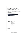
Mode-based Topology
The CLI tree is built on a mode concept where the commands are available according to the interface.
Some of the modes are depicted in Figure 1.
Figure 1. Mode-based CLI
ROOT
The User EXEC commands
are also accessible in the
Privileged EXEC mode.
User EXEC
Enable
Passwd
Correc
Correct
?t
No
Return to the
EXEC prompt
Yes
Privileged EXEC
VLAN
Global Config
Interface Config
Line Config
Access to all commands in the Privileged EXEC mode and below are restricted through a password.
Mode-based Command Hierarchy
The commands in one mode are not available until you switch to that particular mode, with the
exception of the User EXEC mode commands. You can execute the User EXEC mode commands in the
Privileged EXEC mode.
The commands available to you depend upon the mode. To display a list of the available commands and
descriptions of the commands, enter a question mark (?) at the CLI prompt.
Command-Line Interface Modes
27
Command Mode Description
This section describes the CLI command modes.
User EXEC Mode
When you log into the CLI, the User EXEC mode is the initial mode. The User EXEC mode
contains a limited set of commands. The command prompt shown at this level is:
Command Prompt: Switch>
Privileged EXEC Mode
To have access to the full suite of commands, you must enter the Privileged EXEC mode. The
Privileged EXEC mode requires password authentication. From Privileged EXEC mode, you
can issue any EXEC command, enter the VLAN mode, or enter the Global Configuration mode.
The command prompt shown at this level is:
Command Prompt: Switch#
VLAN Mode
This mode groups all the VLAN commands. The command prompt shown at this level is:
Command Prompt: Switch(Vlan)#
Global Config Mode
This mode groups general setup commands and permits you to make modifications to the running configuration. From the Global Configuration mode, you can enter the System Configuration mode, the Physical Port Configuration mode, the Interface Configuration mode, or the
Protocol Specific modes specified below. The command prompt at this level is:
Command Prompt: Switch(Config)#
From the Global Config mode, you can enter the following configuration modes:
Interface Config Mode
Use the Interface commands to enable or modify the operation of an interface.
In this mode, a physical port is set up for a specific logical connection operation. The command prompt at this level is:
Command Prompt: Switch(Interface <slot/port>)#
The resulting prompt for the interface configuration command entered in the Global Configuration mode is shown below:
Switch(Config)# interface 2/1
Switch(Interface 2/1)#
Line Config Mode
Use the Line Config mode to configure the console interface. You can configure the interface
from the console connection or the virtual terminal used with Telnet. The command prompt at
this level is:
Command Prompt: Switch(line)#
28
D-Link DES-3226L Command Line Reference
Flow of Operation
This section describes the flow of operation for the CLI.
1.
Log into the CLI session and enter the User EXEC mode. In the User EXEC mode the $(exec)>
prompt displays on the screen.
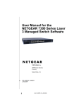
You initiate the parsing process when you type a command and press <ENTER>. If you enter an incorrect
or unavailable command, the output message indicates where the offending entry begins. For instance,
if you enter show arpp brief (notice the extra p) instead of show arp brief, the output message
is $(exec)> show arpp^ brief. $%Invalid input detected at '^' marker. The message
shows you where the invalid input is detected. Figure 2 shows the layout of the output.
Figure 2. Syntax Error Message
(exec) #show arpp brief
^
%Invalid input detected at ‘^’ marker.
After you enter the required parameters, any additional parameters you enter are treated as optional
parameters. If any of the parameters are not recognized, a syntax error message is displayed.
2.
After the command is successfully parsed and validated, the control of execution goes to the corresponding CLI callback function.
3.
For required parameters, the command tree extends until the required parameters make the leaf of
the branch. The callback function is only invoked when all the required parameters are provided.
For optional parameters, the command tree extends until the required parameters and the optional
parameters make the leaf of the branch. However, the callback function is associated with the node
where the required parameters are fetched. The call back function then takes care of the optional
parameters.
4.
Once the control has reached the callback function, the callback function has complete information
about the parameters you enter.
Setup and Management Commands
29
Setup and Management Commands
This section describes the commands you use to configure management access and basic port settings
on the D-Link DES-3226L switch. This section contains the following subsections:
z
z
z
“System Management Commands” on page 29
“System Configuration Commands” on page 35
“SNMP Community Commands” on page 42
The commands in this section are in one of three functional groups:
z
z
z
Show commands display switch settings, statistics, and other information.
Configuration commands configure features and options of the switch. For every configuration
command, there is a show command that displays the configuration setting.
Copy commands transfer or save configuration and informational files to and from the switch.
System Management Commands
You can use telnet to manage the D-Link DES-3226L switch from a remote management system. To
manage the device locally, you can use a direct serial-cable connection. This section describes
commands you use to manage remote and direct connections to the device. To manage the device by
using SNMP, see “SNMP Community Commands” on page 42. To manage the device by using SSH,
see “Secure Shell (SSH) Commands” on page 100.
To manage the device by using telnet, the switch must have an IP address, subnet mask, and default
gateway. You can use network parms to configure the IP address, subnet mask, and default gateway,
or you can use network protocol to configure the switch to request the information from a BOOTP
or DHCP server on your network.
network parms
This command sets the IP Address, subnet mask and gateway of the device. The IP address and the
gateway must be on the same subnet.
Format
network parms <ipaddr> <netmask> [<gateway>]
Mode
Privileged EXEC
network protocol
This command specifies the network configuration protocol to be used. If you modify this value, the
change is effective immediately. The bootp parameter indicates that the switch periodically sends
requests to a Bootstrap Protocol (BootP) server until a response is received. The dhcp parameter
configures the switch to send periodic requests to a DHCP server until a response is received. The
parameter none indicates that the switch should be manually configured with IP information.
Default
none
Format
network protocol {none | bootp | dhcp}
Mode
Privileged EXEC
30
D-Link DES-3226L Command Line Reference
network mgmt_vlan
This command configures the Management VLAN ID.
Default
1
Format
network mgmt_vlan <1-4069>
Mode
Privileged EXEC
no network mgmt_vlan
This command sets the Management VLAN ID to the default.
Format
no network mgmt_vlan <1-4069>
Mode
Privileged EXEC
transport input telnet
This command regulates new telnet sessions. If sessions are enabled, new telnet sessions can be
established until there are no more sessions available. If sessions are disabled, no new telnet sessions
are established. An established session remains active until the session is ended or an abnormal network
error ends the session.
Default
enabled
Format
transport input telnet
Mode
Line Config
no transport input telnet
This command disables telnet sessions. If sessions are disabled, no new telnet sessions are established.
Format
no transport input telnet
Mode
Line Config
telnetcon maxsessions
This command specifies the maximum number of telnet connection sessions that can be established. A
value of 0 indicates that no telnet connection can be established. The range is 0 to 5.
Default
5
Format
telnetcon maxsessions <0-5>
Mode
Privileged EXEC
no telnetcon maxsessions
This command sets the maximum number of telnet connection sessions that can be established to the
default value.
Format
no telnetcon maxsessions
Mode
Privileged EXEC
Setup and Management Commands
31
telnetcon timeout
This command sets the telnet connection session timeout value, in minutes. A session is active as long
as the session has not been idle for the value set. The time is a decimal value from 1 to 160.
Note:
Changing the timeout value for active sessions does not become effective until the
session is reaccessed. Also, any keystroke activates the new timeout duration.
Default
5
Format
telnetcon timeout <1-160>
Mode
Privileged EXEC
no telnetcon timeout
This command sets the telnet connection session timeout value to the default.
Note:
Changing the timeout value for active sessions does not become effective until the
session is reaccessed. Also, any keystroke activates the new timeout duration.
Format
no telnetcon timeout
Mode
Privileged EXEC
bridge aging-time
This command configures the forwarding database address aging timeout in seconds. In an IVL system,
the [fdbid | all] parameter is required. The <seconds> parameter must be within the range of 10 to
1,000,000 seconds. Fdbid (Forwarding database ID) indicates which forwarding database's aging
timeout is being configured. The All option is used to configure all forwarding database's agetime.
Default
300
Format
bridge aging-time <10-1,000,000> [fdbid | all]
Mode
Global Config
no bridge aging-time
This command sets the forwarding database address aging timeout to 300 seconds. In an IVL system,
the [fdbid | all] parameter is required. Fdbid (Forwarding database ID) indicates which forwarding
database's aging timeout is being configured. All is used to configure all forwarding database's agetime.
Format
no bridge aging-time [fdbid | all]
Mode
Global Config
network javamode
This command specifies whether or not the switch should allow access to the Java applet in the header
frame of the Web interface. When access is enabled, the Java applet can be viewed from the Web
interface. When access is disabled, the user cannot view the Java applet.
Default
enabled
Format
network javamode
Mode
Privileged EXEC
32
D-Link DES-3226L Command Line Reference
no network javamode
This command disallows access to the Java applet in the header frame of the Web interface. When
access is disabled, the user cannot view the Java applet.
Format
no network javamode
Mode
Privileged EXEC
network mac-address
This command sets locally administered MAC addresses. The following rules apply:
z
z
z
Bit 6 of byte 0 (called the U/L bit) indicates whether the address is universally administered (b'0')
or locally administered (b'1').
Bit 7 of byte 0 (called the I/G bit) indicates whether the destination address is an individual address
(b'0') or a group address (b'1').
The second character, of the twelve character macaddr, must be 2, 6, A or E.
A locally administered address must have bit 6 On (b'1') and bit 7 Off (b'0').
Format.
network mac-address <macaddr>
Mode.
Privileged EXEC
network mac-type
This command specifies whether the burned in MAC address or the locally-administered MAC address
is used.
Default
burnedin
Format
network mac-type {local | burnedin}
Mode
Privileged EXEC
no network mac-type
This command resets the value of MAC address to its default.
Format
no network mac-type
Mode
Privileged EXEC
serial baudrate
This command specifies the communication rate of the terminal interface. The supported rates are 1200,
2400, 4800, 9600, 19200, 38400, 57600, 115200.
Default
9600
Format
serial baudrate {1200 | 2400 | 4800 | 9600 | 19200 | 38400 |
57600 | 115200}
Mode
Line Config
Setup and Management Commands
33
no serial baudrate
This command sets the communication rate of the terminal interface.
Format
no serial baudrate
Mode
Line Config
serial timeout
This command specifies the maximum connect time (in minutes) without console activity. A value of 0
indicates that a console can be connected indefinitely. The time range is 0 to 160.
Default
5
Format
serial timeout <0-160>
Mode
Line Config
no serial timeout
This command sets the maximum connect time (in minutes) without console activity.
Format
no serial timeout
Mode
Line Config
set prompt
This command changes the name of the prompt. The length of name may be up to 64 alphanumeric
characters.
Format
set prompt <prompt_string>
Mode
Privileged EXEC
show forwardingdb agetime
This command displays the timeout for address aging. In an IVL system, the [fdbid | all] parameter is
required.
Default
all
Format
show forwardingdb agetime [fdbid | all]
Mode
Privileged EXEC
Forwarding DB ID Fdbid (Forwarding database ID) indicates the forwarding database
whose aging timeout is to be shown. The all option is used to display the
aging timeouts associated with all forwarding databases. This field displays
the forwarding database ID in an IVL system.
Agetime
In an IVL system, this parameter displays the address aging timeout for the
associated forwarding database.
34
D-Link DES-3226L Command Line Reference
show network
This command displays configuration settings associated with the switch's network interface. The
network interface is the logical interface used for in-band connectivity with the switch via any of the
switch's front panel ports. The configuration parameters associated with the switch's network interface
do not affect the configuration of the front panel ports through which traffic is switched or routed.
Format
show network
Modes
Privileged EXEC
User EXEC
IP Address
The IP address of the interface. The factory default value is 0.0.0.0
Subnet Mask The IP subnet mask for this interface. The factory default value is 0.0.0.0
Default Gateway The default gateway for this IP interface. The factory default value is
0.0.0.0
Burned In MAC Address The burned in MAC address used for in-band connectivity.
Locally Administered MAC Address If desired, a locally administered MAC address
can be configured for in-band connectivity. To take effect, 'MAC Address
Type' must be set to 'Locally Administered'. Enter the address as twelve hexadecimal digits (6 bytes) with a colon between each byte. Bit 1 of byte 0 must
be set to a 1 and bit 0 to a 0, i.e. byte 0 should have the following mask 'xxxx
xx10'. The MAC address used by this bridge when it must be referred to in a
unique fashion. It is recommended that this be the numerically smallest MAC
address of all ports that belong to this bridge. However it is only required to
be unique. When concatenated with dot1dStpPriority a unique BridgeIdentifier is formed which is used in the Spanning Tree Protocol.
MAC Address Type Specifies which MAC address should be used for in-band connectivity. The choices are the burned in or the Locally Administered address. The
factory default is to use the burned in MAC address.
Network Configuration Protocol Current Indicates which network protocol is being
used. The options are bootp, dhcp, and none.
Java Mode
Specifies if the switch should allow access to the Java applet in the header
frame. Enabled means the applet can be viewed. The factory default is disabled.
Web Mode
Specifies if the switch should allow access to the Web Interface.
show telnetcon
This command displays telnet settings.
Format
show telnetcon
Modes
Privileged EXEC
User EXEC
Remote Connection Login Timeout (minutes) This object indicates the number of
minutes a remote connection session is allowed to remain inactive before
Setup and Management Commands
35
being logged off. May be specified as a number from 1 to 160. The factory
default is 5.
Maximum Number of Remote Connection Sessions This object indicates the number
of simultaneous remote connection sessions allowed. The factory default is 5.
Allow New Telnet Sessions Indicates that new telnet sessions will not be allowed when set
to no. The factory default value is yes.
show serial
This command displays serial communication settings for the switch.
Format
show serial
Modes
Privileged EXEC
User EXEC
Serial Port Login Timeout (minutes) Specifies the time, in minutes, of inactivity on a
Serial port connection, after which the Switch will close the connection. Any
numeric value between 0 and 160 is allowed, the factory default is 5. A value
of 0 disables the timeout.
Baud Rate (bps) The default baud rate at which the serial port will try to connect. The
available values are 1200, 2400, 4800, 9600, 19200, 38400,57600, and
115200 baud. The factory Default is 9600 baud.
Character Size (bits) The number of bits in a character. The number of bits is always 8.
Flow Control Whether Hardware Flow-Control is enabled or disabled. Hardware Flow
Control is always disabled.
Stop Bits
The number of Stop bits per character. The number of Stop bits is always 1.
Parity Type The Parity Method used on the Serial Port. The Parity Method is always
None.
System Configuration Commands
This section describes the commands you use to view and configure port settings.
addport
This command adds one port to the port-channel (LAG). The first interface is a logical slot and port
number of a configured port-channel.
Note:
Before adding a port to a port-channel, set the physical mode of the port. For more
information, see “speed” on page 39.
Format
addport <logical slot/port>
Mode.
Interface Config
36
D-Link DES-3226L Command Line Reference
cablestatus
This command tests the status of the cable attached to an interface.
Format
cablestatus <slot/port>
Mode
Privileged EXEC
auto-negotiate
This command enables automatic negotiation on a port. The default value is enable.
Format
auto-negotiate
Mode
Interface Config
no auto-negotiate
This command disables automatic negotiation on a port.
Note:
Automatic sensing is disabled when automatic negotiation is disabled.
Format
no auto-negotiate
Mode
Interface Config
auto-negotiate all
This command enables automatic negotiation on all ports. The default value is enable.
Format
auto-negotiate all
Mode
Global Config
no auto-negotiate all
This command disables automatic negotiation on all ports.
Format
no auto-negotiate all
Mode
Global Config
deleteport (Interface Config)
This command deletes the port from the port-channel (LAG). The interface is a logical slot and port
number of a configured port-channel.
Format
deleteport <logical slot/port>
Mode
Interface Config
deleteport (Global Config)
This command deletes all configured ports from the port-channel (LAG). The interface is a logical slot
and port number of a configured port-channel.
Format
deleteport {<logical slot/port> | all}
Mode
Global Config
Setup and Management Commands
37
monitor session
This command configures a probe port and a monitored port for monitor session (port monitoring). The
first <slot/port> is the source monitored port and the second <slot/port> is the destination probe port.
The monitor session (port monitoring) mode becomes enabled only when both the probe and monitored
ports are configured. If enabled, the probe port monitors all the traffic received and transmitted on the
physical monitored port.
Format
monitor session <session-id> source interface <slot/port> destination interface <slot/port>
Mode
Global Config
no monitor session
This command removes the monitor session (port monitoring) designation from the source probe port,
the destination monitored port and all VLANs. Once the port is removed from the VLAN, the user must
manually add the port to any desired VLANs.
Note:
This command sets the monitor session (port monitoring) mode to disable.
Format
no monitor session <session-id>
Mode
Global Config
no monitor
This command removes all the source ports and a destination port and restores the default value for
mirroring session mode for all the configured sessions.
Note:
This is a stand-alone “no” command. This command does not have a “normal” form.
Default
enabled
Format
no monitor
Mode
Global config
no monitor session 1
This command removes all the source ports and a destination port of the mirroring session and restores
the default value for mirroring session mode. The <session-id> parameter is an integer value used to
identify the session. In the current version of the software, the <session-id> parameter is always 1.
Note:
This is a stand-alone “no” command and does not have a “normal” form. This command can be issued without regard for the session status (enabled or disabled).
Default
enabled
Format
no monitor session <session-id>
Mode
Global config
38
D-Link DES-3226L Command Line Reference
show monitor session 1
This command displays the port monitoring information for a particular mirroring session.
Note:
The <session-id> parameter is an integer value used to identify the session. In the current version of the software, the <session-id> parameter is always 1.
Format
show monitor session <session-id>
Mode
Privileged EXEC
Session ID
It is an integer value used to identify the session.
Monitor Session Mode It indicates whether the Port Mirroring feature is enabled or disabled for the session identified with <session-id>. The possible values are
Enabled and Disabled.
Probe Port
It is the probe port (destination port) for the session identified with <sessionid>. If probe port is not set, this field is blank.
List of Source Ports It is the list of ports, which are configured as mirrored ports (source
ports) for the session identified with <session-id>. If no source port is configured for the session then this field is blank.
shutdown
This command disables a port.
Default
enabled
Format
shutdown
Mode
Interface Config
no shutdown
This command enables a port.
Format
no shutdown
Mode
Interface Config
shutdown all
This command disables all ports.
Default
enabled
Format
shutdown all
Mode
Global Config
no shutdown all
This command enables all ports.
Format
no shutdown all
Mode
Global Config
Setup and Management Commands
39
speed
This command sets the speed and duplex setting for the interface.
Format
speed {100 | 10} {half-duplex | full-duplex}
Mode
Interface Config
Acceptable values are:
100h
100BASE-T half duplex
100f
100BASE-T full duplex
10h
10BASE-T half duplex
10f
10BASE-T full duplex
speed all
This command sets the speed and duplex setting for all interfaces.
Format
speed all {<100 | 10> <half-duplex | full-duplex>}
Mode
Global Config
Acceptable values are:
100h
100BASE-T half-duplex
100f
100BASE-T full duplex
10h
10BASE-T half duplex
10f
10BASE-T full duplex
storm-control broadcast
This command enables broadcast storm recovery mode. If the mode is enabled, broadcast storm
recovery with high and low thresholds is implemented.
The threshold implementation follows a percentage pattern. If the broadcast traffic on any Ethernet port
exceeds the high threshold percentage (as represented in Table 7) of the link speed, the switch discards
the broadcasts traffic until the broadcast traffic returns to the low threshold percentage or less. The full
implementation is depicted in Table 7.
Table 7. Broadcast Storm Recovery Thresholds
Link Speed
High
Low
10M
20
10
100M
5
2
1000M
5
2
Format
storm-control broadcast
Mode
Global Config
40
D-Link DES-3226L Command Line Reference
no storm-control broadcast
This command disables broadcast storm recovery mode.
The threshold implementation follows a percentage pattern. If the broadcast traffic on any Ethernet port
exceeds the high threshold percentage (as represented in Table 7 on page 39) of the link speed, the
switch discards the broadcasts traffic until the broadcast traffic returns to the low threshold percentage
or less. The full implementation is depicted in Table 7.
Format
no storm-control broadcast
Mode
Global Config
storm-control flowcontrol
This command enables 802.3x flow control for the switch and only applies to full-duplex mode ports.
Note:
802.3x flow control works by pausing a port when the port becomes oversubscribed
and dropping all traffic for small bursts of time during the congestion condition. This
can lead to high-priority and/or network control traffic loss.
Default
disabled
Format
storm-control flowcontrol
Mode
Global Config
no storm-control flowcontrol
This command disables 802.3x flow control for the switch.
Note:
This command only applies to full-duplex mode ports.
Format
no storm-control flowcontrol
Mode
Global Config
show mac-address-table multicast
This command displays the Multicast Forwarding Database (MFDB) information. If the command is
entered with no parameter, the entire table is displayed. This is the same as entering the optional all
parameter. You can display the table entry for one MAC Address by specifying the MAC address as an
optional parameter.
Format
show mac-address-table multicast <macaddr | all>
Mode
Privileged EXEC
MAC Address A multicast MAC address for which the switch has forwarding and or filtering information. The format is two-digit hexadecimal numbers separated by
colons, for example 01:23:45:67:89:AB. In an IVL system the MAC address
will be displayed as a MAC address and VLAN ID combination of 8 bytes.
Type
This displays the type of the entry. Static entries are those that are configured
by the end user. Dynamic entries are added to the table as a result of a learning
process or protocol.
Component
The component that is responsible for this entry in the Multicast Forwarding
Database. Possible values are IGMP Snooping, and Static Filtering.
Setup and Management Commands
41
Description
The text description of this multicast table entry.
Interfaces
The list of interfaces that are designated for forwarding (Fwd:) and filtering
(Flt:).
Forwarding Interfaces The resultant forwarding list is derived from combining all the
component’s forwarding interfaces and removing the interfaces that are listed
as the static filtering interfaces.
show mac-address-table stats
This command displays the Multicast Forwarding Database (MFDB) statistics.
Format
Mode
show mac-address-table stats
Privileged EXEC
Total Entries Displays the total number of entries that can possibly be in the Multicast Forwarding Database table.
Most MFDB Entries Ever Used Displays the largest number of entries that have been
present in the Multicast Forwarding Database table. This value is also known
as the MFDB high-water mark.
Current Entries Displays the current number of entries in the MFDB.
show monitor session
This command displays the port monitoring information for the system.
Format
show monitor session <sessionid>
Mode
Privileged EXEC
Session ID
The session identifying number.
Admin Mode Indicates whether the Port Monitoring feature is enabled or disabled. The
possible values are enable and disable.
Probe Port
The interface configured as the probe port.
Mirrored Port The interface configured as the mirrored port.
show port
This command displays port information.
Format
show port {<slot/port> | all}
Mode
Privileged EXEC
Interface
Valid slot and port number separated by forward slashes.
Type
If not blank, this field indicates that this port is a special type of port. The possible values are:
Mon - this port is a monitoring port. Look at the Port Monitoring screens to
find out more information.
42
D-Link DES-3226L Command Line Reference
Lag - this port is a member of a port-channel (LAG).
Probe - this port is a probe port.
Admin Mode Selects the Port control administration state. The port must be enabled in
order for it to be allowed into the network. - May be enabled or disabled. The
factory default is enabled.
Physical Mode Selects the desired port speed and duplex mode. If auto-negotiation support
is selected, then the duplex mode and speed is set from the auto-negotiation
process. Note that the maximum capability of the port (full duplex -100M) is
advertised. Otherwise, this object determines the port's duplex mode and
transmission rate. The factory default is Auto.
Physical Status Indicates the port speed and duplex mode.
Link Status
Indicates whether the Link is up or down.
Link Trap
This object determines whether or not to send a trap when link status changes.
The factory default is enabled.
LACP Mode Displays whether LACP is enabled or disabled on this port.
show storm-control
This command displays switch configuration information.
Format
show storm-control
Mode
Privileged EXEC
Broadcast Storm Recovery Mode May be enabled or disabled. The factory default is disabled.
802.3x Flow Control Mode May be enabled or disabled. The factory default is disabled.
SNMP Community Commands
You can configure the D-Link DES-3226L switch to act as a Simple Network Management Protocol
(SNMP) agent so that it can communicate with SNMP managers on your network. This section
describes the commands you use to configure SNMP on the D-Link DES-3226L switch.
snmp-server
This command sets the name and the physical location of the switch, and the organization responsible
for the network. The range for <name>, <loc> and <con> is from 1 to 31 alphanumeric characters.
Default
none
Format
snmp-server {sysname <name> | location <loc> | contact <con>}
Mode
Global Config
Setup and Management Commands
43
snmp-server community
This command adds (and names) a new SNMP community. A community <name> is a name associated
with the switch and with a set of SNMP managers that manage it with a specified privileged level. The
length of <name> can be up to 16 case-sensitive characters.
Community names in the SNMP Community Table must be unique. If you make multiple entries using
the same community name, the first entry is kept and processed and all duplicate entries are ignored.
Default
Two default community names: Public and Private. You can replace these
default community names with unique identifiers for each community. The
default values for the remaining four community names are blank.
Format
snmp-server community <name>
Mode
Global Config
no snmp-server community
This command removes this community name from the table. The <name> is the community name to
delete.
Format
no snmp-server community <name>
Mode
Global Config
snmp-server community ipaddr
This command sets a client IP address for an SNMP community. The address is the associated
community SNMP packet-sending address and is used along with the client IP mask value to denote a
range of IP addresses from which SNMP clients may use that community to access the device. A value
of 0.0.0.0 allows access from any IP address. Otherwise, this value is ANDed with the mask to
determine the range of allowed client IP addresses. The name is the applicable community name.
Default
0.0.0.0
Format
snmp-server community ipaddr <ipaddr> <name>
Mode
Global Config
no snmp-server community ipaddr
This command sets a client IP address for an SNMP community to 0.0.0.0. The name is the applicable
community name.
Format
no snmp-server community ipaddr <name>
Mode
Global Config
snmp-server community ipmask
This command sets a client IP mask for an SNMP community. The address is the associated community
SNMP packet sending address and is used along with the client IP address value to denote a range of IP
addresses from which SNMP clients may use that community to access the device.
44
D-Link DES-3226L Command Line Reference
A value of 255.255.255.255 will allow access from only one station, and will use that machine's IP
address for the client IP Address. A value of 0.0.0.0 will allow access from any IP address. The name is
the applicable community name.
Default
0.0.0.0
Format
snmp-server community ipmask <ipmask> <name>
Mode
Global Config
no snmp-server community ipmask
This command sets a client IP mask for an SNMP community to 0.0.0.0. The name is the applicable
community name. The community name may be up to 16 alphanumeric characters.
Format
no snmp-server community ipmask <name>
Mode
Global Config
snmp-server community mode
This command activates an SNMP community. If a community is enabled, an SNMP manager
associated with this community manages the switch according to its access right. If the community is
disabled, no SNMP requests using this community are accepted. In this case the SNMP manager
associated with this community cannot manage the switch until the Status is changed back to Enable.
Default
The default private and public communities are enabled by default. The four
undefined communities are disabled by default.
Format
snmp-server community mode <name>
Mode
Global Config
no snmp-server community mode
This command deactivates an SNMP community. If the community is disabled, no SNMP requests
using this community are accepted. In this case the SNMP manager associated with this community
cannot manage the switch until the Status is changed back to Enable.
Format
no snmp-server community mode <name>
Mode
Global Config
snmp-server community ro
This command restricts access to switch information. The access mode is read-only (also called public).
Format
snmp-server community ro <name>
Mode
Global Config
snmp-server community rw
This command sets the access mode to read/write (also called private).
Format
snmp-server community rw <name>
Mode
Global Config
Setup and Management Commands
snmp-server enable traps
This command enables the Authentication Flag.
Default
enabled
Format
snmp-server enable traps
Mode
Global Config
no snmp-server enable traps
This command disables the Authentication Flag.
Format.
no snmp-server enable traps
Mode
Global Config
snmp-server enable traps linkmode
This command enables Link Up/Down traps for the entire switch. When enabled, link traps are sent
only if the Link Trap flag setting associated with the port is enabled. See “snmp trap link-status” on
page 47.
Default
enabled
Format
snmp-server enable traps linkmode
Mode
Global Config
no snmp-server enable traps linkmode
This command disables Link Up/Down traps for the entire switch.
Format
no snmp-server enable traps linkmode
Mode
Global Config
snmp-server enable traps multiusers
This command enables Multiple User traps. When the traps are enabled, a Multiple User Trap is sent
when a user logs in to the terminal interface (EIA 232 or telnet) and there is an existing terminal
interface session.
Default
enabled
Format
snmp-server enable traps multiusers
Mode
Global Config
no snmp-server enable traps multiusers
This command disables Multiple User traps.
Format
no snmp-server enable traps multiusers
Mode
Global Config
45
46
D-Link DES-3226L Command Line Reference
snmp-server enable traps stpmode
This command enables the sending of new root traps and topology change notification traps.
Default
enabled
Format
snmp-server enable traps stpmode
Mode
Global Config
no snmp-server enable traps stpmode
This command disables the sending of new root traps and topology change notification traps.
Format
no snmp-server enable traps stpmode
Mode
Global Config
snmptrap
This command adds an SNMP trap receiver. The maximum length of <name> is 16 case-sensitive
alphanumeric characters. The <snmpversion> is the version of SNMP. The version parameter options
are snmpv1 or snmpv2.
Note:
The <name> parameter does not need to be unique; however; the <name> and
<ipaddr> pair must be unique. Multiple entries can exist with the same <name>, as
long as they are associated with a different <ipaddr>. The reverse scenario is also
acceptable. The <name> is the community name used when sending the trap to the
receiver, but the <name> is not directly associated with the SNMP Community Table
Default
snmpv2
Format
snmptrap <name> <ipaddr> [snmpversion <snmpversion>]
Mode
Global Config
no snmptrap
This command deletes trap receivers for a community.
Format
no snmptrap <name> <ipaddr>
Mode
Global Config
snmptrap snmpversion
This command modifies the SNMP version of a trap. The maximum length of <name> is 16 casesensitive alphanumeric characters. The <snmpversion> parameter options are snmpv1 or snmpv2.
Note:
This command does not support a “no” form.
Default.
snmpv2
Format
snmptrap snmpversion <name> <ipaddr> <snmpversion>
Mode
Global Config
Setup and Management Commands
47
snmptrap ipaddr
This command assigns an IP address to a specified community name. The maximum length of name is
16 case-sensitive alphanumeric characters. IP addresses in the SNMP trap receiver table must be
unique. If you make multiple entries using the same IP address, the first entry is retained and processed.
All duplicate entries are ignored.
Format
snmptrap ipaddr <name> <ipaddrold> <ipaddrnew>
Mode
Global Config
snmptrap mode
This command activates or deactivates an SNMP trap. Enabled trap receivers are active (able to receive
traps). Disabled trap receivers are inactive (not able to receive traps).
Format
snmptrap mode <name> <ipaddr>
Mode
Global Config
no snmptrap mode
This command deactivates an SNMP trap.
Format
no snmptrap mode <name> <ipaddr>
Mode
Global Config
snmp trap link-status
This command enables link status traps by interface. This command is valid only when the Link Up/
Down Flag is enabled. See “snmp-server enable traps linkmode” on page 45.
Format
snmp trap link-status
Mode
Interface Config
no snmp trap link-status
This command disables link status traps by interface. This command is valid only when the Link Up/
Down Flag is enabled.
Format
no snmp trap link-status
Mode
Interface Config
snmp trap link-status all
This command enables link status traps for all interfaces. This command is valid only when the Link
Up/Down Flag is enabled. See “snmp-server enable traps linkmode” on page 45.
Format
snmp trap link-status all
Mode
Global Config
48
D-Link DES-3226L Command Line Reference
no snmp trap link-status all
This command disables link status traps for all interfaces. This command is valid only when the Link
Up/Down Flag is enabled. See “snmp-server enable traps linkmode” on page 45.
Format
no snmp trap link-status all
Mode
Global Config
show snmpcommunity
This command displays SNMP community information. Six communities are supported. You can add,
change, or delete communities. The switch does not have to be reset for changes to take effect.
The SNMP agent of the switch complies with SNMP Versions 1, 2 or 3. For more information about the
SNMP specification, see the SNMP RFCs. The SNMP agent sends traps through TCP/IP to an external
SNMP manager based on the SNMP configuration (the trap receiver and other SNMP community
parameters).
Format
show snmpcommunity
Mode
Privileged EXEC
SNMP Community Name The community string to which this entry grants access. The
string is case-sensitive and can have up to 16 characters. Each row of this
table must contain a unique community name.
Client IP Address An IP address (or portion thereof) from which this device will accept
SNMP packets with the associated community. The requesting entity's IP
address is ANDed with the Subnet Mask before being compared to the IP
Address. Note: If the Subnet Mask is set to 0.0.0.0, an IP Address of 0.0.0.0
matches all IP addresses. The default value is 0.0.0.0
Client IP Mask A mask to be ANDed with the requesting entity's IP address before comparison with IP Address. If the result matches with IP Address then the
address is an authenticated IP address. For example, if the IP Address =
9.47.128.0 and the corresponding Subnet Mask = 255.255.255.0 a range of
incoming IP addresses would match, i.e. the incoming IP Address could equal
9.47.128.0 - 9.47.128.255. The default value is 0.0.0.0
Access Mode The access level for this community string.
Status
The status of this community access entry.
show trapflags
This command displays trap conditions. Configure which traps the switch should generate by enabling
or disabling the trap condition. If a trap condition is enabled and the condition is detected, the SNMP
agent on the switch sends the trap to all enabled trap receivers. You do not have to reset the switch to
implement the changes. Cold and warm start traps are always generated and cannot be disabled.
Format
show trapflags
Mode
Privileged EXEC
Authentication Flag Can be enabled or disabled. The factory default is enabled. Indicates
whether authentication failure traps will be sent.
Setup and Management Commands
49
Link Up/Down Flag Can be enabled or disabled. The factory default is enabled. Indicates
whether link status traps will be sent.
Multiple Users Flag Can be enabled or disabled. The factory default is enabled. Indicates
whether a trap will be sent when the same user ID is logged into the switch
more than once at the same time (either via telnet or serial port).
Spanning Tree Flag Can be enabled or disabled. The factory default is enabled. Indicates
whether spanning tree traps will be sent.
show snmptrap
This command displays SNMP trap receivers. Trap messages are sent across a network to an SNMP
Network Manager. These messages alert the manager to events occurring within the switch or on the
network. Six trap receivers are simultaneously supported.
Format
show snmptrap
Mode
Privileged EXEC
SNMP Trap Name The community string of the SNMP trap packet sent to the trap manager. The string is case sensitive and can be up to 16 alphanumeric characters.
IP Address
The IP address to receive SNMP traps from this device.
Status
Indicates the receiver's status (enabled or disabled).
50
D-Link DES-3226L Command Line Reference
Switching Commands
51
Switching Commands
This section describes the switching commands available on the D-Link DES-3226L. The switching
commands section includes the following subsections:
z
z
z
z
z
z
z
“Virtual LAN (VLAN) Commands” on page 51
“Protected Ports Commands” on page 56
“Link Aggregation/Port-Channel (802.3AD) Commands” on page 57
“IGMP Snooping Commands” on page 61
“Spanning Tree Protocol (STP) Commands” on page 66
“GVRP Commands” on page 77
“Class of Service (CoS) Commands” on page 79
The commands are divided into three functional groups:
z
z
z
Show commands display switch settings, statistics, and other information.
Configuration commands configure features and options of the switch. For every configuration
command, there is a show command that displays the configuration setting.
Clear commands clear some or all of the settings to factory defaults.
Virtual LAN (VLAN) Commands
VLANs allow users located on different physical networks to be on the same logical network. This
section describes the commands you use to view and configure VLAN settings.
vlan
This command creates a new VLAN and assigns it an ID. The ID is a valid VLAN identification
number between 2 and 4094. The VLAN ID 1 is reserved for the default VLAN.
Format
vlan <2-4094>
Mode
VLAN database
no vlan
This command deletes an existing VLAN. The ID is a valid VLAN identification number between 2 and
4094. The VLAN ID 1 is reserved for the default VLAN.
Format
no vlan <2-4094>
Mode
VLAN database
vlan acceptframe
This command sets the frame acceptance mode per interface. For VLAN Only mode, untagged frames
or priority frames received on this interface are discarded. For Admit All mode, untagged frames or
priority frames received on this interface are accepted and assigned the value of the interface VLAN ID
for this port. With either option, VLAN tagged frames are forwarded in accordance with the IEEE
802.1Q VLAN Specification.
Default
admit all
Format
vlan acceptframe {vlanonly | all}
52
D-Link DES-3226L Command Line Reference
Mode
Interface Config
no vlan acceptframe
This command sets the frame acceptance mode per interface to Admit All. For Admit All mode,
untagged frames or priority frames received on this interface are accepted and assigned the value of the
interface VLAN ID for this port. With either option, VLAN tagged frames are forwarded in accordance
with the IEEE 802.1Q VLAN Specification.
Format
vlan acceptframe {vlanonly | all}
Mode
Interface Config
vlan name
This command changes the name of a VLAN. The name is an alphanumeric string of up to 32
characters, and the ID is a valid VLAN identification number. ID range is 1-4094.
Default
The name for VLAN ID 1 is always Default. The name for other VLANs is
defaulted to a blank string.
Format
vlan name <2-4094> <name>
Mode
VLAN database
no vlan name
This command sets the name of a VLAN to a blank string. The VLAN ID is a valid VLAN
identification number. ID range is 2-4094.
Format
no vlan name <2-4094>
Mode
VLAN database
vlan participation
This command configures the degree of participation for a specific interface in a VLAN. The ID is a
valid VLAN identification number, and the interface is a valid interface number.
Format
vlan participation {exclude | include | auto} <1-4094>
Mode
Interface Config
Participation options are:
include
The interface is always a member of this VLAN. This is equivalent to registration fixed.
exclude
The interface is never a member of this VLAN. This is equivalent to registration forbidden.
vlan participation all
This command configures the degree of participation for all interfaces in a VLAN. The ID is a valid
VLAN identification number.
Format
vlan participation all {exclude | include | auto} <1-4094>
Switching Commands
Mode
53
Global Config
Participation options are:
include
The interface is always a member of this VLAN. This is equivalent to registration fixed.
exclude
The interface is never a member of this VLAN. This is equivalent to registration forbidden.
vlan port acceptframe all
This command sets the frame acceptance mode for all interfaces. The modes are defined as follows:
z
z
VLAN Only mode - Untagged frames or priority frames received on this interface are discarded.
Admit All mode - Untagged frames or priority frames received on this interface are accepted and
assigned the value of the interface VLAN ID for this port.
With either option, VLAN tagged frames are forwarded in accordance with the IEEE 802.1Q VLAN
Specification.
Default
admit all
Format
vlan port acceptframe all {vlanonly | all}
Mode
Global Config
no vlan port acceptframe all
This command sets the frame acceptance mode for all interfaces to Admit All. For Admit All mode,
untagged frames or priority frames received on this interface are accepted and assigned the value of the
interface VLAN ID for this port. With either option, VLAN tagged frames are forwarded in accordance
with the IEEE 802.1Q VLAN Specification.
Format
no vlan port acceptframe all
Mode
Global Config
vlan port pvid all
This command changes the VLAN ID for all interface.
Default
1
Format
vlan port pvid all <1-4094>
Mode
Global Config
no vlan port pvid all
This command sets the VLAN ID for all interfaces to 1.
Format
no vlan port pvid all
Mode
Global Config
54
D-Link DES-3226L Command Line Reference
vlan port tagging all
This command configures the tagging behavior for all interfaces in a VLAN to enabled. If tagging is
enabled, traffic is transmitted as tagged frames. If tagging is disabled, traffic is transmitted as untagged
frames. The ID is a valid VLAN identification number.
Format
vlan port tagging all <1-4094>
Mode
Global Config
no vlan port tagging all
This command configures the tagging behavior for all interfaces in a VLAN to disabled. If tagging is
disabled, traffic is transmitted as untagged frames. The ID is a valid VLAN identification number.
Format
no vlan port tagging all
Mode
Global Config
vlan pvid
This command changes the VLAN ID per interface.
Default
1
Format
vlan pvid <1-4094>
Mode
Interface Config
no vlan pvid
This command sets the VLAN ID per interface to 1.
Format
no vlan pvid
Mode
Interface Config
vlan tagging
This command configures the tagging behavior for a specific interface in a VLAN to enabled. If tagging
is enabled, traffic is transmitted as tagged frames. If tagging is disabled, traffic is transmitted as
untagged frames. The ID is a valid VLAN identification number.
Format
vlan tagging <1-4094>
Mode
Interface Config
no vlan tagging
This command configures the tagging behavior for a specific interface in a VLAN to disabled. If
tagging is disabled, traffic is transmitted as untagged frames. The ID is a valid VLAN identification
number.
Format
no vlan tagging <1-4094>
Mode
Interface Config
Switching Commands
55
show vlan
This command displays detailed information, including interface information, for a specific VLAN. The
ID is a valid VLAN identification number.
Format
show vlan <vlanid>
Modes
Privileged EXEC
User EXEC
VLAN ID
There is a VLAN Identifier (VID) associated with each VLAN. The range of
the VLAN ID is 1 to 4094.
VLAN Name A string associated with this VLAN as a convenience. It can be up to 32
alphanumeric characters long, including blanks. The default is blank. VLAN
ID 1 always has a name of `Default`. This field is optional.
VLAN Type Type of VLAN, which can be Default (VLAN ID = 1) or static (one that is
configured and permanently defined).
Interface
Valid slot and port number separated by forward slashes. It is possible to set
the parameters for all ports by using the selectors on the top line.
Current
Determines the degree of participation of this port in this VLAN. The permissible values are:
Include - This port is always a member of this VLAN. This is equivalent to
registration fixed in the IEEE 802.1Q standard.
Exclude - This port is never a member of this VLAN. This is equivalent to
registration forbidden in the IEEE 802.1Q standard.
Configured
Determines the configured degree of participation of this port in this VLAN.
The permissible values are:
Include - This port is always a member of this VLAN. This is equivalent to
registration fixed in the IEEE 802.1Q standard.
Exclude - This port is never a member of this VLAN. This is equivalent to
registration forbidden in the IEEE 802.1Q standard.
Tagging
Select the tagging behavior for this port in this VLAN.
Tagged - specifies to transmit traffic for this VLAN as tagged frames.
Untagged - specifies to transmit traffic for this VLAN as untagged frames.
show vlan brief
This command displays a list of all configured VLANs.
Format
show vlan brief
Modes
Privileged EXEC
User EXEC
VLAN ID
There is a VLAN Identifier (vlanid) associated with each VLAN. The range
of the VLAN ID is 1 to 4094.
56
D-Link DES-3226L Command Line Reference
VLAN Name A string associated with this VLAN as a convenience. It can be up to 32
alphanumeric characters long, including blanks. The default is blank. VLAN
ID 1 always has a name of `Default`. This field is optional.
VLAN Type Type of VLAN, which can be Default (VLAN ID = 1) or static (one that is
configured and permanently defined).
show vlan port
This command displays VLAN port information.
Format
show vlan port {<slot/port> | all}
Modes
Privileged EXEC
User EXEC
Interface
Valid slot and port number separated by forward slashes. It is possible to set
the parameters for all ports by using the selectors on the top line.
Port VLAN ID The VLAN ID that this port will assign to untagged frames or priority
tagged frames received on this port. The value must be for an existing VLAN.
The factory default is 1.
Acceptable Frame Types Specifies the types of frames that may be received on this port.
The options are 'VLAN only' and 'Admit All'. When set to 'VLAN only',
untagged frames or priority tagged frames received on this port are discarded.
When set to 'Admit All', untagged frames or priority tagged frames received
on this port are accepted and assigned the value of the Port VLAN ID for this
port. With either option, VLAN tagged frames are forwarded in accordance to
the 802.1Q VLAN specification.
Protected Ports Commands
This section describes commands you use to configure and view protected ports on a switch. Protected
ports do not forward traffic to each other, even if they are on the same VLAN. However, protected ports
can forward traffic to all unprotected ports in their group. Unprotected ports can forward traffic to both
protected and unprotected ports. Ports are unprotected by default.
switchport protected
Use this command to configure a protected port. The groupid parameter identifies the set of protected
ports to which this interface is assigned. You can only configure an interface as protected in one group.
The name parameter is an optional name associated with this group. The name can be up to 32
alphanumeric characters long, including blanks.
Note:
Port protection occurs within a single switch. Protected port configuration does not
affect traffic between ports on two different switches.
No traffic forwarding is possible between two protected ports.
Default
Unprotected
Format
switchport protected [<groupid>] [name <name>]
Mode
Interface Config
Switching Commands
57
no switchport protected
Use this command to configure a port as unprotected. The groupid parameter identifies the set of
protected ports to which this interface is assigned. You can only configure an interface as protected in
one group. The name parameter is an optional name associated with this group. The name can be up to
32 alphanumeric characters long, including blanks.
Format
no switchport protected [<groupid>] [name <name>]
Mode
Interface Config
show switchport protected
This command displays the status of all the interfaces, including protected and unprotected interfaces.
Format
show switchport protected [<groupid>]
Mode
User EXEC
Privileged EXEC
Group ID
The number that identifies the protected port group.
Name
An optional name of the protected port group. The name can be up to 32
alphanumeric characters long, including blanks. The default is blank.
List of Physical Ports List of ports, which are configured as protected for the group identified with <groupid>. If no port is configured as protected for this group, this
field is blank.
Link Aggregation/Port-Channel (802.3AD) Commands
This section describes the commands you use to configure link aggregation groups (LAG), which are
also called port-channels. Link aggregation allows you to combine multiple full duplex Ethernet links
into a single logical link. Network devices treat the aggregation as if it were a single link, which
increases fault tolerance and provides load sharing. The LAG feature initially load shares traffic based
upon the source and destination MAC address.
The ports you combine to form a LAG must have equal port speed capabilities. In other words, each
LAG must use all Fast Ethernet (10/100) ports or all Gigabit Ethernet (10/100/1000) ports, but not both,
regardless of what you set the actual link speed to be.
You can create two LAGs on the switch if you use Fast Ethernet ports. You can create one LAG if you
use Gigabit Ethernet ports.
Note:
Assign the LAG VLAN membership after you create a LAG. If you do not assign
VLAN membership, the LAG might become a member of the management VLAN
which can result in learning and switching issues.
Note:
The D-Link DES-3226L switch does not support spanning tree protocol (STP) on
dynamic LAGs. If you want to run STP on a LAG, you must configure static capability on the LAG. For more information, see “port-channel staticcapability” on page 58.
58
D-Link DES-3226L Command Line Reference
port-channel
This command configures a new port-channel and generates a logical slot/port number for the portchannel. The <name> field is a character string which allows the dash “-” character as well as
alphanumeric characters. Display this number using the “show port-channel” command.
Note:
Before you include a port in a port-channel, set the port physical mode. For more
information, see “speed” on page 39.
Format
port-channel <name>
Mode
Global Config
no port-channel
This command deletes a port-channel (LAG).
Format
no port-channel {<logical slot/port> | all}
Mode
Global Config
clear port-channel
Use this command to clear all configured port channels.
Format
clear port-channel
Mode
Privileged EXEC
port-channel staticcapability
This command enables the support of port-channels (static link aggregations) on the device. By default,
the static capability for all port-channels is disabled.
Default
disabled
Format
port-channel staticcapability
Mode
Global Config
no port-channel staticcapability
This command disables the support of static port-channels on the device.
Format
no port-channel staticcapability
Mode
Global Config
port lacpmode
This command enables Link Aggregation Control Protocol (LACP) on a port.
Default
enabled
Format
port lacpmode
Mode
Interface Config
Switching Commands
59
no port lacpmode
This command disables Link Aggregation Control Protocol (LACP) on a port.
Format
no port lacpmode
Mode
Interface Config
port lacpmode all
This command enables Link Aggregation Control Protocol (LACP) on all ports.
Format
port lacpmode all
Mode
Global Config
no port lacpmode all
This command disables Link Aggregation Control Protocol (LACP) on all ports.
Format
no port lacpmode all
Mode
Global Config
port-channel adminmode
This command enables a port-channel (LAG). The interface is a logical slot/port for a configured portchannel. The option [all] sets every configured port-channel with the same administrative mode
setting.
Format
port-channel adminmode [all]
Mode
Global Config
no port-channel adminmode
This command disables a port-channel (LAG). The interface is a logical slot/port for a configured portchannel. The option [all] sets every configured port-channel with the same administrative mode
setting.
Format
no port-channel adminmode [all]
Mode
Global Config
port-channel linktrap
This command enables link trap notifications for the port-channel (LAG). The interface is a logical slot/
port for a configured port-channel. The option [all] sets every configured port-channel with the same
administrative mode setting.
Default
enabled
Format
port-channel linktrap {<logical slot/port> | all}
Mode
Global Config
60
D-Link DES-3226L Command Line Reference
no port-channel linktrap
This command disables link trap notifications for the port-channel (LAG). The interface is a logical slot
and port for a configured port-channel. The option all sets every configured port-channel with the
same administrative mode setting.
Format
no port-channel linktrap {<logical slot/port> | all}
Mode
GlobalConfig
port-channel name
This command defines a name for the port-channel (LAG). The interface is a logical slot/port for a
configured port-channel, and name is an alphanumeric string up to 15 characters. This command is used
to modify the name that was associated with the port-channel when it was created.
Format
port-channel name {<logical slot/port> | all | <name>}
Mode
Global Config
show port-channel brief
This command displays the static capability of all port-channels (LAGs) on the device as well as a
summary of individual port-channels.
Format
show port-channel brief
Mode
Privileged EXEC
User EXEC
Static Capability This field displays whether or not the device has static capability enabled.
For each port-channel the following information is displayed:
Name
This field displays the name of the port-channel.
Link State
This field indicates whether the link is up or down.
Mbr Ports
This field lists the ports that are members of this port-channel, in <slot/port>
notation.
Active Ports This field lists the ports that are actively participating in this port-channel.
show port-channel
This command displays an overview of all port-channels (LAGs) on the switch.
Format
show port-channel {<logical slot/port> | all}
Modes
Privileged EXEC
User EXEC
Logical slot/port Valid slot and port number separated by forward slashes.
Lag Name
The name of this port-channel (LAG). You may enter any string of up to 15
alphanumeric characters.
Link State
Indicates whether the Link is up or down.
Admin Mode May be enabled or disabled. The factory default is enabled.
Switching Commands
61
Link Trap Mode This object determines whether or not to send a trap when link status
changes. The factory default is enabled.
STP Mode
The Spanning Tree Protocol Administrative Mode associated with the port or
port-channel (LAG). The possible values are:
Disable - Spanning tree is disabled for this port.
Enable - Spanning tree is enabled for this port.
Mbr Ports
A listing of the ports that are members of this port-channel (LAG), in slot/port
notation. There can be a maximum of eight ports assigned to a given portchannel (LAG).
Port Speed
Speed of the port-channel port.
Type
This field displays the status designating whether a particular port-channel
(LAG) is statically or dynamically maintained.
Static - The port-channel is statically maintained.
Dynamic - The port-channel is dynamically maintained.
Active Ports This field lists ports that are actively participating in the port-channel (LAG).
IGMP Snooping Commands
This section describes the commands you use to configure Internet Group Management Protocol
(IGMP) Snooping on the D-Link DES-3226L switch. The IGMP Snooping feature can help conserve
bandwidth because it allows the switch to forward IP multicast traffic only to connected hosts that
request multicast traffic.
set igmp
This command enables IGMP Snooping on the system (Global Config Mode) or an interface (Interface
Config Mode). This command also enables IGMP snooping on a particular VLAN and on all interfaces
participating in this VLAN.
If an interface has IGMP Snooping enabled and you enlist it as a member of a port-channel (LAG),
IGMP Snooping functionality is disabled on that interface. IGMP Snooping functionality is re-enabled
if you remove port-channel (LAG) membership from an interface that has IGMP Snooping enabled.
The IGMP application supports the following activities:
z
z
z
Validation of the IP header checksum (as well as the IGMP header checksum) and discarding of the
frame upon checksum error.
Maintenance of the forwarding table entries based on the MAC address versus the IP address.
Flooding of unregistered multicast data packets to all ports in the VLAN.
Default
disabled
Format
set igmp <vlanId>
Modes
Global Config
Interface Config
Vlan Mode
62
D-Link DES-3226L Command Line Reference
no set igmp
This command disables IGMP Snooping on the system.
Format
no set igmp <vlanId>
Modes
Global Config
Interface Config
Vlan Mode
set igmp interfacemode
This command enables IGMP Snooping on all interfaces. If an interface has IGMP Snooping enabled
and you enlist it as a member of a port-channel (LAG), IGMP Snooping functionality is disabled on that
interface. IGMP Snooping functionality is re-enabled if you remove port-channel (LAG) membership
from an interface that has IGMP Snooping enabled.
Default
disabled
Format
set igmp interfacemode
Mode
Global Config
no set igmp interfacemode
This command disables IGMP Snooping on all interfaces.
Format
no set igmp interfacemode
Mode
Global Config
set igmp fast-leave
This command enables or disables IGMP Snooping fast-leave admin mode on a selected interface or
VLAN. Enabling fast-leave allows the switch to immediately remove the layer 2 LAN interface from its
forwarding table entry upon receiving an IGMP leave message for that multicast group without first
sending out MAC-based general queries to the interface.
You should enable fast-leave admin mode only on VLANs where only one host is connected to each
layer 2 LAN port. This prevents the inadvertent dropping of the other hosts that were connected to the
same layer 2 LAN port but were still interested in receiving multicast traffic directed to that group.
Also, fast-leave processing is supported only with IGMP version 2 hosts.
Default
disable
Format
set igmp fast-leave <vlanId>
Modes
Interface Config
Vlan Mode
no set igmp fast-leave
This command disables IGMP Snooping fast-leave admin mode on a selected interface.
Format
no set igmp fast-leave <vlanId>
Modes
Interface Config
Vlan Mode
Switching Commands
63
set igmp groupmembership-interval
This command sets the IGMP Group Membership Interval time on one interface or all interfaces. The
Group Membership Interval time is the amount of time in seconds that a switch waits for a report from a
particular group on a particular interface before deleting the interface from the entry. This value must be
greater than the IGMPv3 Maximum Response time value. The range is 2 to 3600 seconds.
Default
260 seconds
Format
set igmp groupmembership-interval <vlanId> <2-3600>
Modes
Interface Config
Global Config
no set igmp groupmembership-interval
This command sets the IGMPv3 Group Membership Interval time to the default value.
Format
no set igmp groupmembership-interval
Modes
Interface Config
Global Config
set igmp maxresponse
This command sets the IGMP Maximum Response time for the system, on a particular interface or
VLAN. The Maximum Response time is the amount of time in seconds that a switch will wait after
sending a query on an interface because it did not receive a report for a particular group in that interface.
This value must be less than the IGMP Query Interval time value. The range is 1 to 3599 seconds.
Default
10 seconds
Format
set igmp maxresponse <1-3599>
Modes
Global Config
Interface Config
VLAN Mode
no set igmp maxresponse
This command sets the IGMP Maximum Response time (on the interface or VLAN) to the default
value.
Format
no set igmp maxresponse
Modes
Global Config
Interface Config
VLAN Mode
set igmp mcrtexpiretime
This command sets the Multicast Router Present Expiration time. The time is set for the system, on a
particular interface or VLAN.
This is the amount of time in seconds that a switch waits for a query to be received on an interface
before the interface is removed from the list of interfaces with multicast routers attached. The range is 0
to 3600 seconds. A value of 0 indicates an infinite time-out, i.e. no expiration.
64
D-Link DES-3226L Command Line Reference
Default
0
Format
set igmp mcrtexpiretime <vlanId> <0-3600>
Modes
Global Config
Interface Config
no set igmp mcrtexpiretime
This command sets the Multicast Router Present Expiration time to 0. The time is set for the system, on
a particular interface or a VLAN.
Format
no set igmp mcrtexpiretime <vlanId>
Modes
Global Config
Interface Config
set igmp mrouter
This command configures the VLAN ID (<vlanId>) that has the multicast router mode enabled.
Format
set igmp mrouter <vlanId>
Mode
Interface Config
no set igmp mrouter
This command disables multicast router mode for a particular VLAN ID (<vlanId>).
Format
no set igmp mrouter <vlanId>
Mode
Interface Config
set igmp mrouter interface
This command configures the interface as a multicast router interface. When configured as a multicast
router interface, the interface is treated as a multicast router interface in all VLANs.
Default
disabled
Format
set igmp mrouter interface
Mode
Interface Config
no set igmp mrouter interface
This command disables the status of the interface as a statically configured multicast router interface.
Format
no set igmp mrouter interface
Mode
Interface Config
Switching Commands
65
show igmpsnooping
This command displays IGMP Snooping information. Configured information is displayed whether or
not IGMP Snooping is enabled.
Format
show igmpsnooping [<slot/port> | <vlanId>]
Mode
Privileged EXEC
When you do not specify a parameter, the command displays the following information:
Admin Mode This indicates whether IGMP Snooping is active on the switch.
Interfaces Enabled for IGMP Snooping This is the list of interfaces on which IGMP
Snooping is enabled.
Multicast Control Frame Count This displays the number of multicast control frames
that are processed by the CPU.
VLANs Enabled for IGMP Snooping Displays the list of VLANs on which IGMP
Snooping is enabled.
When you specify the <slot/port> or VLAN ID values, the following information prints to the screen:
IGMP Snooping Admin Mode This indicates whether IGMP Snooping is active on the
specified interface or VLAN.
Fast Leave Mode Indicates whether Fast Leave mode is enabled.
Group Membership Interval Displays the amount of time in seconds that the device
waits for a report from a particular group on a particular interface before
deleting the interface from the entry.
Max Response Time Displays the amount of time the switch waits after it sends a query on
an interface, participating in the VLAN, because it did not receive a report for
a particular group on that interface.
Multicast Router Present Expiration Time Displays the amount of time to wait before
removing an interface that is participating in the VLAN from the list of interfaces with multicast routers attached. The interface is removed if a query is
not received.
show igmpsnooping mrouter interface
This command displays information about statically configured ports.
Format
show igmpsnooping mrouter interface <slot/port>
Mode
Privileged EXEC
Interface
Shows the port on which multicast router information is being displayed.
Multicast Router Attached Indicates whether or not multicast router is statically enabled
on the interface.
VLAN ID
Displays the list of VLANs of which the interface is a member.
66
D-Link DES-3226L Command Line Reference
show igmpsnooping mrouter vlan
This command displays IGMP snooping information for a port that participates in a VLAN.
Format
show igmpsnooping mrouter vlan <slot/port>
Mode
Privileged EXEC
Slot/Port
Shows the port on which multicast router information is being displayed.
VLAN ID
Displays the list of VLANs of which the interface is a member.
show mac-address-table igmpsnooping
This command displays the IGMP Snooping entries in the Multicast Forwarding Database (MFDB)
table.
Format
show mac-address-table igmpsnooping
Mode
Privileged EXEC
MAC Address A multicast MAC address for which the switch has forwarding or filtering
information. The format is two-digit hexadecimal numbers that are separated
by colons, for example 01:23:45:67:89:AB. In an IVL system the MAC
address is displayed as a MAC address and VLAN ID combination of 8 bytes.
Type
Displays the type of the entry. Static entries are those that are configured by
the end user. Dynamic entries are added to the table as a result of a learning
process or protocol.
Description
The text description of this multicast table entry.
Interfaces
The list of interfaces that are designated for forwarding (Fwd:) and filtering
(Flt:).
Spanning Tree Protocol (STP) Commands
This section describes the commands you use to configure Spanning Tree Protocol (STP) on the D-Link
DES-3226L switch. STP helps prevent network loops, duplicate messages, and network instability.
Note:
STP is disabled by default. When you enable STP on the switch, STP is still disabled
on each port.
Note:
The D-Link DES-3226L switch does not support spanning tree protocol (STP) on
dynamic LAGs. If you want to run STP on a LAG, you must configure static capability on the LAG. For more information, see “port-channel staticcapability” on page 58.
spanning-tree
This command sets the STP mode for a specific port-channel (LAG). This is the value specified for STP
Mode on the Port Configuration Menu. The default is 802.1D. The interface is a logical slot/port for a
configured port-channel. The all option sets all configured port-channels (LAGs) with the same
option. If you do not specify any parameters, the spanning tree command enables the STP mode.
The mode is one of the following:
Switching Commands
67
802.1d
IEEE 802.1D-compliant STP mode is used
fast
Fast STP mode is used
off
STP is turned off
Default
disabled
Format
spanning-tree {<logical slot/port> | all | {off | 802.1d | fast}}
Mode
Global Config
no spanning-tree
This command sets the spanning-tree operational mode to disabled. While disabled, the spanning-tree
configuration is retained and can be changed, but is not activated.
Format
no spanning-tree
Mode
Global Config
spanning-tree bpdumigrationcheck
This command enables BPDU migration check on a given interface. The all option enables BPDU
migration check on all interfaces.
Format
spanning-tree bpdumigrationcheck {<slot/port> | all}
Mode
Global Config
spanning-tree configuration name
This command sets the Configuration Identifier Name for use in identifying the configuration that this
switch is currently using. The <name> is a string of up to 32 characters.
Default
The base MAC address displayed using hexadecimal notation.
Format
spanning-tree configuration name <name>
Mode
Global Config
no spanning-tree configuration name
This command resets the Configuration Identifier Name to its default.
Format
no spanning-tree configuration name
Mode
Global Config
spanning-tree configuration revision
This command sets the Configuration Identifier Revision Level is a number in the range of 0 to 65535
and is used to identify the configuration that this switch is currently using.
Default
0
Format
spanning-tree configuration revision <0-65535>
Mode
Global Config
68
D-Link DES-3226L Command Line Reference
no spanning-tree configuration revision
This command sets the Configuration Identifier Revision Level the default value of 0.
Format
no spanning-tree configuration revision
Mode
Global Config
spanning-tree edgeport
This command specifies that this port is an Edge Port within the common and internal spanning tree.
This allows this port to transition to Forwarding State without delay.
Format
spanning-tree edgeport
Mode
Interface Config
no spanning-tree edgeport
This command specifies that this port is not an Edge Port within the common and internal spanning tree.
Format
no spanning-tree edgeport
Mode
Interface Config
spanning-tree forceversion
This command sets the Force Protocol Version parameter to a new value. The Force Protocol Version
can be one of the following:
z
z
z
802.1d - ST BPDUs are transmitted rather than MST BPDUs (IEEE 802.1d functionality supported)
802.1w - RST BPDUs are transmitted rather than MST BPDUs (IEEE 802.1w functionality supported)
802.1s - MST BPDUs are transmitted (IEEE 802.1s functionality supported)
Default
802.1s
Format
spanning-tree forceversion <802.1d | 802.1w | 802.1s>
Mode
Global Config
no spanning-tree forceversion
This command sets the Force Protocol Version parameter to the default value, i.e. 802.1s.
Format
no spanning-tree forceversion
Mode
Global Config
spanning-tree forward-time
This command sets the Bridge Forward Delay parameter to a new value for the common and internal
spanning tree. The forward-time value is in seconds within a range of 4 to 30, with the value being
greater than or equal to “(Bridge Max Age / 2) + 1”.
Default
15
Format
spanning-tree forward-time <4-30>
Mode
Global Config
Switching Commands
69
no spanning-tree forward-time
This command sets the Bridge Forward Delay parameter to the default value of 15.
Format
no spanning-tree forward-time
Mode
Global Config
spanning-tree hello-time
This command sets the Admin Hello Time parameter to a new value for the common and internal
spanning tree. The hello time <value> is in whole seconds within a range of 1 to 10, with the value
being less than or equal to (Bridge Max Age / 2) - 1.
Default
2
Format
spanning-tree hello-time <1-10>
Mode
Interface Config
no spanning-tree hello-time
This command sets the admin Hello Time parameter for the common and internal spanning tree to two.
Format
no spanning-tree hello-time
Mode
Interface Config
spanning-tree max-age
This command sets the Bridge Max Age parameter to a new value for the common and internal
spanning tree. The max-age value is in seconds within a range of 6 to 40, with the value being less than
or equal to 2 x (Bridge Forward Delay - 1).
Default
20
Format
spanning-tree max-age <6-40>
Mode
Global Config
no spanning-tree max-age
This command sets the Bridge Max Age parameter for the common and internal spanning tree to 20.
Format
no spanning-tree max-age
Mode
Global Config
spanning-tree max-hops
This command sets the MSTP Max Hops parameter to a new value for the common and internal
spanning tree. The max-hops value is a range from 1 to 127.
Default
20
Format
spanning-tree max-hops <1-127>
Mode
Global Config
70
D-Link DES-3226L Command Line Reference
no spanning-tree max-hops
This command sets the Bridge Max Hops parameter for the common and internal spanning tree to the
default value.
Format
no spanning-tree max-hops
Mode
Global Config
spanning-tree mst
This command sets the Path Cost or Port Priority for this port within the multiple spanning tree instance
or in the common and internal spanning tree. If you specify an <mstid> parameter that corresponds to an
existing multiple spanning tree instance, the configurations are done for that multiple spanning tree
instance. If you specify 0 (defined as the default CIST ID) as the <mstid>, the configurations are done
for the common and internal spanning tree instance.
If you specify the cost option, the command sets the path cost for this port within a multiple spanning
tree instance or the common and internal spanning tree instance, depending on the <mstid> parameter.
You can set the path cost as a number in the range of 1 to 200000000 or auto. If you select auto the path
cost value is set based on Link Speed.
If you specify the external-cost option, this command sets the external-path cost for MST instance ‘0’
i.e. CIST instance. You can set the external cost as a number in the range of 1 to 200000000 or auto. If
you specify auto, the external path cost value is set based on Link Speed.
If you specify the port-priority option, this command sets the priority for this port within a specific
multiple spanning tree instance or the common and internal spanning tree instance, depending on the
<mstid> parameter. The port-priority value is a number in the range of 0 to 240 in increments of 16.
Default
cost: auto; external-cost: auto; port-priority: 128
Format
spanning-tree mst <mstid> {{cost <1-200000000> | auto} |
{external-cost <1-200000000> | auto}| port-priority <0-240>}
Mode
Interface Config
no spanning-tree mst
This command sets the Path Cost or Port Priority for this port within the multiple spanning tree instance,
or in the common and internal spanning tree to the respective default values. If you specify an <mstid>
parameter that corresponds to an existing multiple spanning tree instance, you are configuring that
multiple spanning tree instance. If you specify 0 (defined as the default CIST ID) as the <mstid>, you
are configuring the common and internal spanning tree instance.
If the you specify cost, this command sets the path cost for this port within a multiple spanning tree
instance or the common and internal spanning tree instance, depending on the <mstid> parameter, to the
default value, i.e. a path cost value based on the Link Speed. If you specify external-cost, this
command sets the external path cost for this port for mst ‘0’ instance, to the default value, i.e. a path
cost value based on the Link Speed. If you specify port-priority, this command sets the priority for this
port within a specific multiple spanning tree instance or the common and internal spanning tree
instance, depending on the <mstid> parameter, to the default value, i.e. 128.
Format
no spanning-tree mst <mstid> {cost | external-cost | port-priority}
Mode
Interface Config
Switching Commands
71
spanning-tree mst instance
This command adds a multiple spanning tree instance to the switch. The parameter <mstid> is a number
within a range of 1 to 4094, that corresponds to the new instance ID to be added. The maximum number
of multiple instances supported by the D-Link DES-3226L switch is 4.
Format
spanning-tree mst instance <mstid>
Mode
Global Config
no spanning-tree mst instance
This command removes a multiple spanning tree instance from the switch and reallocates all VLANs
allocated to the deleted instance to the common and internal spanning tree. The parameter <mstid> is a
number that corresponds to the desired existing multiple spanning tree instance to be removed.
Format
no spanning-tree mst instance <mstid>
Mode
Global Config
spanning-tree mst priority
This command sets the bridge priority for a specific multiple spanning tree instance. The parameter
<mstid> is a number that corresponds to the desired existing multiple spanning tree instance. The
priority value is a number within a range of 0 to 61440 in increments of 4096.
If you specify 0 (defined as the default CIST ID) as the <mstid>, this command sets the Bridge Priority
parameter to a new value for the common and internal spanning tree. The bridge priority value is a
number within a range of 0 to 61440. The twelve least significant bits are masked according to the
802.1s specification. This causes the priority to be rounded down to the next lower valid priority.
Default
32768
Format
spanning-tree mst priority <mstid> <0-61440>
Mode
Global Config
no spanning-tree mst priority
This command sets the bridge priority for a specific multiple spanning tree instance to the default value,
i.e. 32768. The parameter <mstid> is a number that corresponds to the desired existing multiple
spanning tree instance.
If 0 (defined as the default CIST ID) is passed as the <mstid>, this command sets the Bridge Priority
parameter for the common and internal spanning tree to the default value, i.e. 32768.
Format
spanning-tree mst priority <mstid>
Mode
Global Config
spanning-tree mst vlan
This command adds an association between a multiple spanning tree instance and a VLAN so that the
VLAN is no longer associated with the common and internal spanning tree. The parameter <mstid> is a
72
D-Link DES-3226L Command Line Reference
number that corresponds to the desired existing multiple spanning tree instance. The <vlanid>
corresponds to an existing VLAN ID.
Format
spanning-tree mst vlan <mstid> <vlanid>
Mode
Global Config
no spanning-tree mst vlan
This command removes an association between a multiple spanning tree instance and a VLAN so that
the VLAN is again be associated with the common and internal spanning tree. The parameter <mstid> is
a number that corresponds to the desired existing multiple spanning tree instance. The <vlanid>
corresponds to an existing VLAN ID.
Format
no spanning-tree mst vlan <mstid> <vlanid>
Mode
Global Config
spanning-tree port mode
This command sets the Administrative Switch Port State for this port to enabled.
Default
disabled
Format
spanning-tree port mode
Mode
Interface Config
no spanning-tree port mode
This command sets the Administrative Switch Port State for this port to disabled.
Format
no spanning-tree port mode
Mode
Interface Config
spanning-tree port mode all
This command sets the Administrative Switch Port State for all ports to enabled.
Default
disabled
Format
spanning-tree port mode all
Mode
Global Config
no spanning-tree port mode all
This command sets the Administrative Switch Port State for all ports to disabled.
Format
no spanning-tree port mode all
Mode
Global Config
Switching Commands
73
show spanning-tree
This command displays spanning tree settings for the common and internal spanning tree, when the
optional parameter “brief” is not included in the command. The following details are displayed.
Format
show spanning-tree <brief>
Modes
Privileged EXEC
User EXEC
Bridge Priority Specifies the bridge priority for the Common and Internal Spanning tree
(CST). The value lies between 0 and 61440. It is displayed in multiples of
4096.
Bridge Identifier The bridge identifier for the CST. It is made up using the bridge priority
and the base MAC address of the bridge.
Time Since Topology Change Time in seconds.
Topology Change Count Number of times changed.
Topology Change Boolean value of the Topology Change parameter for the switch indicating if a topology change is in progress on any port assigned to the common
and internal spanning tree.
Designated Root The bridge identifier of the root bridge. It is made up from the bridge priority and the base MAC address of the bridge.
Root Path Cost Value of the Root Path Cost parameter for the common and internal spanning tree.
Root Port Identifier Identifier of the port to access the Designated Root for the CST.
Root Port Max Age Derived value.
Root Port Bridge Forward Delay Derived value.
Hello Time Configured value of the parameter for the CST.
Bridge Hold Time Minimum time between transmission of Configuration Bridge Protocol
Data Units (BPDUs)
Bridge Max Hops Bridge max-hops count for the device.
CST Regional Root Bridge Identifier of the CST Regional Root. It is made up using the
bridge priority and the base MAC address of the bridge.
Regional Root Path Cost Path Cost to the CST Regional Root.
Associated FIDs List of forwarding database identifiers currently associated with this
instance.
Associated VLANs List of VLAN IDs currently associated with this instance.
When the “brief” optional parameter is included, this command displays spanning tree settings for the
bridge. In this case, the following details are displayed.
Bridge Priority Configured value.
74
D-Link DES-3226L Command Line Reference
Bridge Identifier The bridge identifier for the selected MST instance. It is made up using
the bridge priority and the base MAC address of the bridge.
Bridge Max Age Configured value.
Bridge Max Hops Bridge max-hops count for the device.
Bridge Hello Time Configured value.
Bridge Forward Delay Configured value.
Bridge Hold Time Minimum time between transmission of Configuration Bridge Protocol
Data Units (BPDUs)
show spanning-tree summary
This command displays spanning tree settings and parameters for the switch. The following details are
displayed on execution of the command.
Format
show spanning-tree summary
Modes
Privileged EXEC
User EXEC
Spanning Tree Adminmode Enabled or disabled.
Spanning Tree Version Version of 802.1 currently supported (IEEE 802.1s, IEEE 802.1w,
or IEEE 802.1d) based upon the Force Protocol Version parameter.
Configuration Name Identifier used to identify the configuration currently being used.
Configuration Revision Level Identifier used to identify the configuration currently
being used.
Configuration Digest Key Identifier used to identify the configuration currently being
used.
MST Instances List of all multiple spanning tree instances configured on the switch
show spanning-tree interface
This command displays the settings and parameters for a specific switch port within the common and
internal spanning tree. The <slot/port> is the desired switch port. The following details are displayed on
execution of the command.
Format
show spanning-tree interface <slot/port>
Mode
Privileged EXEC
User EXEC
Hello Time
Admin hello time for this port.
Port mode
Enabled or disabled.
Port Up Time Since Counters Last Cleared Time since port was reset, displayed in
days, hours, minutes, and seconds.
STP BPDUs Transmitted Spanning Tree Protocol Bridge Protocol Data Units sent
Switching Commands
75
STP BPDUs Received Spanning Tree Protocol Bridge Protocol Data Units
received.
RST BPDUs Transmitted Rapid Spanning Tree Protocol Bridge Protocol Data Units sent
RST BPDUs Received Rapid Spanning Tree Protocol Bridge Protocol Data Units
received.
MSTP BPDUs Transmitted Multiple Spanning Tree Protocol Bridge Protocol Data Units
sent
MSTP BPDUs Received Multiple Spanning Tree Protocol Bridge Protocol Data Units
received.
show spanning-tree mst port detailed
This command displays the detailed settings and parameters for a specific switch port within a
particular multiple spanning tree instance. The parameter <mstid> is a number that corresponds to the
desired existing multiple spanning tree instance. The <slot/port> is the desired switch port.
Format
show spanning-tree mst port detailed <mstid> <slot/port>
Mode
Privileged EXEC
User EXEC
MST Instance ID The ID of the existing MST instance.
Port Identifier The port identifier for the specified port within the selected MST instance. It
is made up from the port priority and the interface number of the port.
Port Priority The priority for a particular port within the selected MST instance. The port priority is
displayed in multiples of 16.
Port Forwarding State Current spanning tree state of this port.
Port Role
Each enabled MST Bridge Port receives a Port Role for each spanning tree.
The port role is one of the following values: Root Port, Designated Port,
Alternate Port, Backup Port, Master Port or Disabled Port
Auto-Calculate Port Path Cost This indicates whether auto calculation for port path cost
is enabled.
Port Path Cost Configured value of the Internal Port Path Cost parameter.
Auto-Calculate External Port Path Cost This indicates whether auto calculation for
external port path cost is enabled.
External Port Path Cost Configured value of the external Port Path Cost parameter.
Designated Root The Identifier of the designated root for this port.
Designated Port Cost Path Cost offered to the LAN by the Designated Port
Designated Bridge Bridge Identifier of the bridge with the Designated Port.
Designated Port Identifier Port on the Designated Bridge that offers the lowest cost to
the LAN.
76
D-Link DES-3226L Command Line Reference
If you specify 0 (defined as the default CIST ID) as the <mstid>, this command displays the settings and
parameters for a specific switch port within the common and internal spanning tree. The <slot/port> is
the desired switch port. In this case, the following are displayed.
Port Identifier The port identifier for this port within the CST.
Port Priority The priority of the port within the CST.
Port Forwarding State The forwarding state of the port within the CST.
Port Role
The role of the specified interface within the CST.
Port Path Cost The configured path cost for the specified interface.
Designated Root Identifier of the designated root for this port within the CST.
Designated Port Cost Path Cost offered to the LAN by the Designated Port.
Designated Bridge The bridge containing the designated port
Designated Port Identifier Port on the Designated Bridge that offers the lowest cost to
the LAN
Topology Change Acknowledgement Value of flag in next Configuration Bridge Protocol Data Unit (BPDU) transmission indicating if a topology change is in
progress for this port.
Hello Time
The hello time in use for this port.
Edge Port
The configured value indicating if this port is an edge port.
Edge Port Status The derived value of the edge port status. True if operating as an edge
port; false otherwise.
Point To Point MAC Status Derived value indicating if this port is part of a point to
point link.
CST Regional Root The regional root identifier in use for this port.
CST Port Cost The configured path cost for this port.
show spanning-tree mst port summary
This command displays the settings of one or all ports within the specified multiple spanning tree
instance. The parameter <mstid> indicates a particular MST instance. The parameter {<slot/port> | all}
indicates the desired switch port or all ports. If you specify 0 (defined as the default CIST ID) as the
<mstid>, the status summary displays for one or all ports within the common and internal spanning tree.
Format
show spanning-tree mst port summary <mstid> {<slot/port> | all}
Modes
Privileged EXEC
User EXEC
MST Instance ID The MST instance associated with this port.
Interface
Valid slot and port number separated by forward slashes.
Type
Currently not used.
STP State
The forwarding state of the port in the specified spanning tree instance
Switching Commands
Port Role
The role of the specified port within the spanning tree.
Link Status
The operational status of the link. Possible values are “Up” or “Down”.
Link Trap
The link trap configuration for the specified interface.
77
show spanning-tree mst summary
This command displays summary information about all multiple spanning tree instances in the switch.
On execution, the following details are displayed.
Format
show spanning-tree mst summary
Modes
Privileged EXEC
User EXEC
MST Instance ID List List of multiple spanning trees IDs currently configured.
For each MSTID:
Associated FIDs List of forwarding database identifiers associated with this instance.
Associated VLANs List of VLAN IDs associated with this instance.
show spanning-tree vlan
This command displays the association between a VLAN and a multiple spanning tree instance. The
<vlanid> corresponds to an existing VLAN ID.
Format
show spanning-tree vlan <vlanid>
Modes
Privileged EXEC
User EXEC
VLAN Identifier The VLANs associated with the selected MST instance.
Associated Instance Identifier for the associated multiple spanning tree instance or “CST”
if associated with the common and internal spanning tree.
GVRP Commands
This section describes the commands you use to configure and view GARP VLAN Registration
Protocol (GVRP) information. GVRP-enabled switches exchange VLAN configuration information,
which allows GVRP to provide dynamic VLAN creation on trunk ports and automatic VLAN pruning.
NOTE: If GVRP is disabled, the system does not forward GVRP messages.
set gvrp adminmode
This command enables GVRP.
Default
disabled
Format
set gvrp adminmode
Mode
Privileged EXEC
78
D-Link DES-3226L Command Line Reference
no set gvrp adminmode
This command disables GVRP.
Format
no set gvrp adminmode
Mode
Privileged EXEC
set gvrp interfacemode
This command enables GVRP.
Default
disabled
Format
set gvrp interfacemode
Modes
Interface Config
Global Config
no set gvrp interfacemode
This command disables GVRP. If GVRP is disabled, Join Time, Leave Time and Leave All
Time have no effect.
Format
no set gvrp interfacemode
Modes
Interface Config
Global Config
show gvrp configuration
This command displays Generic Attributes Registration Protocol (GARP) information for one
or all interfaces.
Format
show gvrp configuration {<slot/port> | all}
Modes
Privileged EXEC
User EXEC
Interface
Valid slot and port number separated by forward slashes.
Join Timer
Specifies the interval between the transmission of GARP PDUs registering
(or re-registering) membership for an attribute. Current attributes are a VLAN
or multicast group. There is an instance of this timer on a per-Port, per-GARP
participant basis. Permissible values are 10 to 100 centiseconds (0.1 to 1.0
seconds). The factory default is 20 centiseconds (0.2 seconds). The finest
granularity of specification is one centisecond (0.01 seconds).
Leave Timer
Specifies the period of time to wait after receiving an unregister request for an
attribute before deleting the attribute. Current attributes are a VLAN or multicast group. This may be considered a buffer time for another station to assert
registration for the same attribute in order to maintain uninterrupted service.
There is an instance of this timer on a per-Port, per-GARP participant basis.
Permissible values are 20 to 600 centiseconds (0.2 to 6.0 seconds). The factory default is 60 centiseconds (0.6 seconds).
LeaveAll Timer This Leave All Time controls how frequently LeaveAll PDUs are generated. A LeaveAll PDU indicates that all registrations will shortly be deregistered. Participants will need to rejoin in order to maintain registration. There
Switching Commands
79
is an instance of this timer on a per-Port, per-GARP participant basis. The
Leave All Period Timer is set to a random value in the range of LeaveAllTime
to 1.5*LeaveAllTime. Permissible values are 200 to 6000 centiseconds (2 to
60 seconds). The factory default is 1000 centiseconds (10 seconds).
Port GMRP Mode Indicates the GARP Multicast Registration Protocol (GMRP) administrative mode for the port, which is enabled or disabled (default). If this parameter
is disabled, Join Time, Leave Time and Leave All Time have no effect.
Class of Service (CoS) Commands
This section describes the commands you use to configure and view Class of Service (CoS) settings on
the D-Link DES-3226L switch. The commands in this section allow you to control the priority and
transmission rate of traffic.
Note:
Commands you issue in the Interface Config mode affect a single interface, while
commands you issue in the 'Global Config' mode affect all interfaces.
classofservice dot1p-mapping
This command maps an 802.1p priority to an internal traffic class. The <userpriority> parameter is the
802.1p priority level. The value ranges from 0-7. The <trafficclass> parameter specifies the traffic class
to map to the 802.1p priority. The value ranges from 0-2. The 'no' form of this command is not
supported.
Format
classofservice dot1p-mapping <userpriority> <trafficclass>
Modes
Global Config
classofservice trust dot1p
This command sets the class of service trust mode to 802.1p packet markings.
Format
classofservice trust dot1p
Mode
Global Config
no classofservice trust
This command sets the interface mode to untrusted.
Format
no classofservice trust
Modes
Global Config
traffic-shape
This command specifies the maximum transmission bandwidth limit for the interface as a whole. Traffic
shaping smoothes temporary traffic bursts over time so that the transmitted traffic rate is bounded. The
<0-100> value is the percentage of port speed. For example, a value of 20 means that the port speed for
egress traffic is at 20% of the maximum rate. The <rate 0-10000000> is the absolute bandwidth
value of the port in kbps in increments of 64 kbps.
80
D-Link DES-3226L Command Line Reference
The default traffic shaping value is 0, meaning no upper limit is enforced, which allows the interface to
transmit up to its maximum traffic rate.
Default
0
Format
traffic-shape {<0-100> | rate <0-10000000>}
Modes
Global Config
Interface Config
Note:
The value is independent of any per-queue maximum bandwidth value(s) in effect for
the interface and should be considered as a second-level transmission rate control
mechanism that regulates the output of the entire interface regardless of which queues
originate the outbound traffic.
no traffic-shape
This command restores the egress port speed to the default value.
Format
no traffic-shape
Modes
Global Config
Interface Config
rate-limit
This command allows you to limit the rate of ingress traffic arriving on the port. You can set the rate on
a per-port basis or on all ports. The <0-100> value is the percentage of bandwidth to limit. For
example, a value of 20 means that the port speed for ingress traffic is at 20% of the maximum rate. The
<rate 0-10000000> value is the absolute bandwidth value in increments of 64 kbps.
The default ingress rate shaping value is 0, meaning no upper limit is enforced, which allows the port to
accept up to its maximum traffic rate.
Default
0
Format
rate-limit {<0-100> | rate <0-10000000>}
Modes
Global Config
Interface Config
no rate-limit
This command restores the ingress port speed to the default value.
Format
no rate-limit
Modes
Global Config
Interface Config
show classofservice dot1p-mapping
This command displays the current Dot1p (802.1p) priority mapping to internal traffic classes for a
specific interface. The slot/port parameter is optional and is only valid on platforms that support
independent per-port class of service mappings. If specified, the 802.1p mapping table of the interface is
displayed. If omitted, the most recent global configuration settings are displayed.
Format
show classofservice dot1p-mapping [slot/port]
Switching Commands
Mode
81
Privileged EXEC
The following information is repeated for each user priority.
User Priority The 802.1p user priority value.
Traffic Class The traffic class internal queue identifier to which the user priority value is
mapped.
show classofservice trust
This command displays the current trust mode setting for a specific interface. The slot/port parameter is
optional and is only valid on platforms that support independent per-port class of service mappings. If
specified, the port trust mode of the interface is displayed. If omitted, the most recent global
configuration settings are displayed.
Format
show classofservice trust [<slot/port>]
Mode
Privileged EXEC
show interfaces cos-queue
This command displays the class-of-service queue configuration for the specified interface. The slot/
port parameter is optional and is only valid on platforms that support independent per-port class of
service mappings. If specified, the class-of-service queue configuration of the interface is displayed. If
omitted, the most recent global configuration settings are displayed.
Format
show interfaces cos-queue [<slot/port>]
Mode
Privileged EXEC
Interface
This displays the slot/port of the interface. If displaying the global configuration, this output line is replaced with a Global Config indication.
Intf Shaping Rate The maximum transmission bandwidth limit for the interface as a
whole. It is independent of any per-queue maximum bandwidth value(s) in
effect for the interface. This is a configured value.
82
D-Link DES-3226L Command Line Reference
Access and Security Commands
83
Access and Security Commands
This section provides a detailed explanation of the access and security commands available on the DLink DES-3226L switch. The security commands section includes the following subsections:
z
z
z
z
z
“User Account Commands” on page 83
“Port-Based Network Access Control Commands” on page 86
“RADIUS Commands” on page 95
“Secure Shell (SSH) Commands” on page 100
“Hypertext Transfer Protocol (HTTP) Commands” on page 102
This section provides a detailed explanation of the security commands. The commands are divided into
the following groups:
z
z
Configuration commands are used to configure features and options of the switch. For every configuration command there is a show command that will display the configuration setting.
Show commands are used to display switch settings, statistics and other information.
User Account Commands
The D-Link DES-3226L switch has two default users: admin and guest. The admin user can view and
configure system settings, and the guest user can view settings. This section describes the commands
you use to add, manage, and delete system users.
Note:
You cannot delete the admin user, and there is only one user allowed with read/write
privileges. You can configure up to five read-only users on the system.
users name
This command adds a new user account, if space permits. The account <username> can be up to eight
characters in length. You can use alphanumeric characters as well as the dash (‘-’) and underscore (‘_’).
The <username> is not case-sensitive.
You can define up to six user names.
Format
users name <username>
Mode
Global Config
no users name
This command removes a user account.
Format
no users name <username>
Mode
Global Config
Note:
You cannot delete the “admin” user account.
users passwd
Use this command to change a password. Passwords are a maximum of eight alphanumeric characters.
If a user is authorized for authentication or encryption is enabled, the password length must be at least
84
D-Link DES-3226L Command Line Reference
eight alphanumeric characters. The username and password are not case-sensitive. When you change a
password, a prompt asks for the old password. If there is no password, press enter.
Default.
no password
Format.
users passwd <username>
Mode
Global Config
no users passwd
This command sets the password of an existing user to blank. When you change a password, a prompt
asks for the old password. If there is no password, press enter.
Format.
no users passwd <username>
Mode.
Global Config
users snmpv3 accessmode
This command specifies the snmpv3 access privileges for the specified login user. The valid
accessmode values are readonly or readwrite. The <username> is the login user name for which
the specified access mode applies. The default is readwrite for the “admin” user and readonly for
all other users
Default
admin - readwrite; other - readonly
Format
users snmpv3 accessmode <username> {readonly | readwrite}
Mode
Global Config
no users snmpv3 accessmode
This command sets the snmpv3 access privileges for the specified user as readwrite for the “admin”
user and readonly for all other users. The <username> value is the user name for which the specified
access mode will apply.
Format
no users snmpv3 accessmode <username>
Mode
Global Config
users snmpv3 authentication
This command specifies the authentication protocol to be used for the specified user. The valid
authentication protocols are none, md5 or sha. If you specify md5 or sha, the login password is also
used as the snmpv3 authentication password and therefore must be at least eight characters in length.
The <username> is the user name associated with the authentication protocol.
Default
no authentication
Format
users snmpv3 authentication <username> {none | md5 | sha}
Mode
Global Config
Access and Security Commands
85
no users snmpv3 authentication
This command sets the authentication protocol to be used for the specified user to none. The
<username> is the user name for which the specified authentication protocol is used.
Format
users snmpv3 authentication <username>
Mode
Global Config
users snmpv3 encryption
This command specifies the encryption protocol used for the specified user. The valid encryption
protocols are des or none.
If you select des, you can specify the required key on the command line. The encryption key must be 8
to 64 characters long. If you select the des protocol but do not provide a key, the user is prompted for
the key. When you use the des protocol, the login password is also used as the snmpv3 encryption
password, so it must be a minimum of eight characters. If you select none, you do not need to provide a
key.
The <username> value is the login user name associated with the specified encryption.
Default
no encryption
Format
users snmpv3 encryption <username> {none | des[key]}
Mode
Global Config
no users snmpv3 encryption
This command sets the encryption protocol to none. The <username> is the login user name for which
the specified encryption protocol will be used.
Format
no users snmpv3 encryption <username>
Mode
Global Config
show loginsession
This command displays current telnet and serial port connections to the switch.
Format
show loginsession
Mode
Privileged EXEC
ID
Login Session ID
User Name
The name the user will use to login using the serial port or Telnet.
Connection From IP address of the Telnet client machine or EIA-232 for the serial port
connection.
Idle Time
Time this session has been idle.
Session Time Total time this session has been connected.
86
D-Link DES-3226L Command Line Reference
show users
This command displays the configured user names and their settings. This command is only available
for users with Read/Write privileges. The SNMPv3 fields will only be displayed if SNMP is available on the
system.
Format
show users
Mode
Privileged EXEC
User Name
The name the user enters to login using the serial port, Telnet or Web.
Access Mode Shows whether the user is able to change parameters on the switch (Read/
Write) or is only able to view them (Read Only). As a factory default, the
“admin” user has Read/Write access and the “guest” has Read Only access.
There can only be one Read/Write user and up to five Read Only users.
SNMPv3 Access Mode This field displays the SNMPv3 Access Mode. If the value is set to
the SNMPv3 user is able to set and retrieve parameters on the
system. If the value is set to ReadOnly, the SNMPv3 user is only able to
retrieve parameter information. The SNMPv3 access mode may be different
than the CLI and Web access mode.
ReadWrite,
SNMPv3 Authentication This field displays the authentication protocol to be used for the
specified login user.
SNMPv3 Encryption This field displays the encryption protocol to be used for the specified login user.
disconnect
This command closes a telnet session.
Format
disconnect {<sessionID> | all}
Mode
Privileged EXEC
Port-Based Network Access Control Commands
This section describes the commands you use to configure Port-Based Network Access Control (IEEE
802.1X). Use Port-Based Network Access Control to prevent unauthenticated devices from accessing
the network through the directly-connected port.
authentication login
This command creates an authentication login list. The <listname> is any character string and is not
case sensitive. Up to 10 authentication login lists can be configured on the switch. When a list is
created, the authentication method “local” is set as the first method.
When the optional parameters “Option1”, “Option2” and/or “Option3” are used, an ordered list of
methods are set in the authentication login list. If the authentication login list does not exist, a new
authentication login list is first created and then the authentication methods are set in the authentication
login list. The maximum number of authentication login methods is three. The possible method values
are local, radius and reject.
Access and Security Commands
87
The value of local indicates that the user’s locally stored ID and password are used for authentication.
The value of radius indicates that the user’s ID and password will be authenticated using the RADIUS
server. The value of reject indicates the user is never authenticated.
To authenticate a user, the first authentication method in the user’s login (authentication login list) is
attempted. D-Link DES-3226L software does not utilize multiple entries in the user’s login. If the first
entry returns a timeout, the user authentication attempt fails.
Note:
The default login list included with the default configuration can not be changed.
Format
authentication login <listname> [method1 [method2 [method3]]]
Mode
Global Config
no authentication login
This command deletes the specified authentication login list. The attempt to delete fails if any of the
following conditions are true:
z
z
z
The login list name is invalid or does not match an existing authentication login list
The specified authentication login list is assigned to any user or to the non configured user for any
component
The login list is the default login list included with the default configuration and was not created
using ‘authentication login’. The default login list cannot be deleted.
Format
no authentication login <listname>
Mode
Global Config
clear dot1x statistics
This command resets the 802.1x statistics for the specified port or for all ports.
Format
clear dot1x statistics {<slot/port> | all}
Mode
Privileged EXEC
clear radius statistics
This command is used to clear all RADIUS statistics.
Format
clear radius statistics
Mode
Privileged EXEC
dot1x default-login
This command assigns the authentication login list to use for non-configured users for 802.1x port
security. This setting is over-ridden by the authentication login list assigned to a specific user if the user
is configured locally. If this value is not configured, users will be authenticated using local
authentication only.
Format
dot1x defaultlogin <listname>
Mode
Global Config
88
D-Link DES-3226L Command Line Reference
dot1x initialize
This command begins the initialization sequence on the specified port. This command is only valid if
the control mode for the specified port is 'auto'. If the control mode is not 'auto' an error will be returned.
Format
dot1x initialize <slot/port>
Mode
Privileged EXEC
dot1x login
This command assigns the specified authentication login list to the specified user for 802.1x port
security. The <user> parameter must be a configured user and the <listname> parameter must be a
configured authentication login list.
Format
dot1x login <user> <listname>
Mode
Global Config
dot1x max-req
This command sets the maximum number of times the authenticator state machine on this port will
transmit an EAPOL EAP Request/Identity frame before timing out the supplicant. The <count> value
must be in the range 1 - 10.
Default
2
Format
dot1x max-req <count>
Mode
Interface
Config
no dot1x max-req
This command sets the maximum number of times the authenticator state machine on this port will
transmit an EAPOL EAP Request/Identity frame before timing out the supplicant.
Format
no dot1x max-req
Mode
Interface Config
dot1x port-control
This command sets the authentication mode to be used on the specified port. The control mode may be
one of the following.
force-unauthorized: The authenticator PAE unconditionally sets the controlled port to unauthorized.
force-authorized: The authenticator PAE unconditionally sets the controlled port to authorized.
auto: The authenticator PAE sets the controlled port mode to reflect the outcome of the authentication
exchanges between the supplicant, authenticator and the authentication server.
Default
auto
Format
dot1x port-control {force-unauthorized |
auto}
Mode
Interface Config
force-authorized |
Access and Security Commands
89
no dot1x port-control
This command sets the authentication mode to be used on the specified port to 'auto'.
Format
no dot1x port-control
Mode
Interface Config
dot1x port-control all
This command sets the authentication mode on all ports. The control mode can be:
force-unauthorized: The authenticator PAE unconditionally sets the controlled port to unauthorized.
force-authorized: The authenticator PAE unconditionally sets the controlled port to authorized.
auto: The authenticator PAE sets the controlled port mode to reflect the outcome of the authentication
exchanges between the supplicant, authenticator and the authentication server.
Default
auto
Format
dot1x port-control all {force-unauthorized | force-authorized | auto}
Mode
Global Config
no dot1x port-control All
This command sets the authentication mode to be used on all ports to 'auto'.
Format
no dot1x port-control all
Mode
Global Config
dot1x re-authenticate
This command begins the re-authentication sequence on the specified port. This command is only valid
if the control mode for the specified port is 'auto'. Otherwise, an error message appears.
Format
dot1x re-authenticate <slot/port>
Mode
Privileged EXEC
dot1x re-authentication
This command enables re-authentication of the supplicant for the specified port.
Default
disabled
Format
dot1x re-authentication
Mode
Interface Config
no dot1x re-authentication
This command disables re-authentication of the supplicant for the specified port.
Format
no dot1x re-authentication
Mode
Interface Config
90
D-Link DES-3226L Command Line Reference
dot1x system-auth-control
This command is used to enable the dot1x authentication support on the switch. By default, the
authentication support is disabled. While disabled, the dot1x configuration is retained and can be
changed, but is not activated.
Default
disabled
Format
dot1x system-auth-control
Mode
Global Config
no dot1x system-auth-control
This command is used to disable the dot1x authentication support on the switch.
Format
no dot1x system-auth-control
Mode
Global Config
dot1x timeout
This command sets the value, in seconds, of the timer used by the authenticator state machine on this
port. Depending on the token used and the value (in seconds) passed, various timeout configurable
parameters are set. The following tokens are supported.
reauth-period: Sets the value, in seconds, of the timer used by the authenticator state machine on this
port to determine when re-authentication of the supplicant takes place. The reauth-period must be a
value in the range 1 - 65535.
quiet-period: Sets the value, in seconds, of the timer used by the authenticator state machine on this port
to define periods of time in which it will not attempt to acquire a supplicant. The quiet-period must be a
value in the range 0 - 65535.
tx-period: Sets the value, in seconds, of the timer used by the authenticator state machine on this port to
determine when to send an EAPOL EAP Request/Identity frame to the supplicant. The quiet-period
must be a value in the range 1 - 65535.
supp-timeout: Sets the value, in seconds, of the timer used by the authenticator state machine on this
port to timeout the supplicant. The supp-timeout must be a value in the range 1 - 65535.
server-timeout: Sets the value, in seconds, of the timer used by the authenticator state machine on this
port to timeout the authentication server. The supp-timeout must be a value in the range 1 - 65535.
Default
reauth-period: 3600 seconds
quiet-period: 60 seconds
tx-period: 30 seconds
supp-timeout: 30 seconds
server-timeout: 30 seconds
Format
dot1x timeout {{reauth-period <seconds>} | {quiet-period <seconds>} | {tx-period <seconds>} | {supp-timeout <seconds>} |
{server-timeout <seconds>}}
Mode
Interface Config
Access and Security Commands
91
no dot1x timeout
This command sets the value, in seconds, of the timer used by the authenticator state machine on this
port to the default values. Depending on the token used, the corresponding default values are set.
Format
no dot1x timeout {reauth-period | quiet-period | tx-period |
supp-timeout | server-timeout}
Mode
Interface Config
dot1x user
This command adds the specified user to the list of users with access to the specified port or all ports.
The <user> parameter must be a configured user.
Format
dot1x user <user> {<slot/port> | all}
Mode
Global Config
no dot1x user
This command removes the user from the list of users with access to the specified port or all ports.
Format
no dot1x user <user> {<slot/port> | all}
Mode
Global Config
users defaultlogin
This command assigns the authentication login list to use for non-configured users when attempting to
log in to the system. This setting is overridden by the authentication login list assigned to a specific user
if the user is configured locally. If this value is not configured, users will be authenticated using local
authentication only.
Format
users defaultlogin <listname>
Mode
Global Config
users login
This command assigns the specified authentication login list to the specified user for system login. The
<user> must be a configured <user> and the <listname> must be a configured login list.
If the user is assigned a login list that requires remote authentication, all access to the interface from all
CLI, web, and telnet sessions will be blocked until the authentication is complete.
Note that the login list associated with the ‘admin’ user can not be changed to prevent accidental
lockout from the switch.
Format
users login <user> <listname>
Mode
Global Config
92
D-Link DES-3226L Command Line Reference
show authentication
This command displays the ordered authentication methods for all authentication login lists.
Format.
show authentication
Mode
Privileged EXEC
Authentication Login List This displays the authentication login listname.
Method 1
This displays the first method in the specified authentication login list, if any.
Method 2
This displays the second method in the specified authentication login list, if
any.
Method 3
This displays the third method in the specified authentication login list, if any.
show authentication users
This command displays information about the users assigned to the specified authentication login list. If
the login is assigned to non-configured users, the user “default” will appear in the user column.
Format
show authentication users <listname>
Mode
Privileged EXEC
User
This field displays the user assigned to the specified authentication login list.
Component
This field displays the component (User or 802.1x) for which the authentication login list is assigned.
show dot1x
This command is used to show a summary of the global dot1x configuration, summary information of
the dot1x configuration for a specified port or all ports, the detailed dot1x configuration for a specified
port and the dot1x statistics for a specified port - depending on the tokens used.
Format
show dot1x [{summary {<slot/port> | all} | {detail <slot/port>} |
{statistics <slot/port>}]
Mode
Privileged EXEC
If none of the optional parameters are used, the global dot1x configuration summary is displayed.
Administrative mode Indicates whether authentication control on the switch is enabled or
disabled.
If the optional parameter 'summary {<slot/port> | all}' is used, the dot1x configuration for the specified
port or all ports are displayed.
Port
The interface whose configuration is displayed.
Control Mode The configured control mode for this port. Possible values are force-unauthorized | force-authorized | auto.
Operating Control Mode The control mode under which this port is operating. Possible
values are authorized | unauthorized.
Reauthentication Enabled Indicates whether re-authentication is enabled on this port.
Access and Security Commands
93
Key Transmission Enabled Indicates if the key is transmitted to the supplicant for the
specified port.
If the optional parameter 'detail <slot/port>' is used, the detailed dot1x configuration for the specified
port are displayed.
Port
The interface whose configuration is displayed.
Protocol Version The protocol version associated with this port. The only possible value is
1, corresponding to the first version of the dot1x specification.
PAE Capabilities The port access entity (PAE) functionality of this port. Possible values
are Authenticator or Supplicant.
Authenticator PAE State Current state of the authenticator PAE state machine. Possible
values are Initialize, Disconnected, Connecting, Authenticating, Authenticated, Aborting, Held, ForceAuthorized, and ForceUnauthorized.
Backend Authentication State Current state of the backend authentication state machine.
Possible values are Request, Response, Success, Fail, Timeout, Idle, and Initialize.
Quiet Period The timer used by the authenticator state machine on this port to define periods of time in which it will not attempt to acquire a supplicant. The value is
expressed in seconds and will be in the range 0 and 65535.
Transmit Period The timer used by the authenticator state machine on the specified port to
determine when to send an EAPOL EAP Request/Identity frame to the supplicant. The value is expressed in seconds and will be in the range of 1 and
65535.
Supplicant Timeout The timer used by the authenticator state machine on this port to timeout the supplicant. The value is expressed in seconds and will be in the range
of 1 and 65535.
Server Timeout The timer used by the authenticator on this port to timeout the authentication server. The value is expressed in seconds and will be in the range of 1
and 65535.
Maximum Requests The maximum number of times the authenticator state machine on
this port will retransmit an EAPOL EAP Request/Identity before timing out
the supplicant. The value will be in the range of 1 and 10.
Reauthentication Period The timer used by the authenticator state machine on this port to
determine when reauthentication of the supplicant takes place. The value is
expressed in seconds and will be in the range of 1 and 65535.
Reauthentication Enabled Indicates if reauthentication is enabled on this port. Possible
values are ‘True” or “False”.
Key Transmission Enabled Indicates if the key is transmitted to the supplicant for the
specified port. Possible values are True or False.
Control Direction Indicates the control direction for the specified port or ports. Possible
values are both or in.
94
D-Link DES-3226L Command Line Reference
If the optional parameter 'statistics <slot/port>' is used, the dot1x statistics for the specified port are
displayed.
Port
The interface whose statistics are displayed.
EAPOL Frames Received The number of valid EAPOL frames of any type that have
been received by this authenticator.
EAPOL Frames Transmitted The number of EAPOL frames of any type that have been
transmitted by this authenticator.
EAPOL Start Frames Received The number of EAPOL start frames that have been
received by this authenticator.
EAPOL Logoff Frames Received The number of EAPOL logoff frames that have been
received by this authenticator.
Last EAPOL Frame Version The protocol version number carried in the most recently
received EAPOL frame.
Last EAPOL Frame Source The source MAC address carried in the most recently
received EAPOL frame.
EAP Response/Id Frames Received The number of EAP response/identity frames that
have been received by this authenticator.
EAP Response Frames Received The number of valid EAP response frames (other than
resp/id frames) that have been received by this authenticator.
EAP Request/Id Frames Transmitted The number of EAP request/identity frames that
have been transmitted by this authenticator.
EAP Request Frames Transmitted The number of EAP request frames (other than
request/identity frames) that have been transmitted by this authenticator.
Invalid EAPOL Frames Received The number of EAPOL frames that have been
received by this authenticator in which the frame type is not recognized.
EAP Length Error Frames Received The number of EAPOL frames that have been
received by this authenticator in which the frame type is not recognized.
show dot1x users
This command displays 802.1x port security user information for locally configured users.
Format
show dot1x users <slot/port>
Mode
Privileged EXEC
User
Users configured locally to have access to the specified port.
show users authentication
This command displays all user and all authentication login information. It also displays the
authentication login list assigned to the default user.
Format
show users authentication
Mode
Privileged EXEC
Access and Security Commands
User
95
This field lists every user that has an authentication login list assigned.
System Login This field displays the authentication login list assigned to the user for system login.
802.1x Port Security This field displays the authentication login list assigned to the user
for 802.1x port security.
RADIUS Commands
This section describes the commands you use to configure the D-Link DES-3226L switch to use a
Remote Authentication Dial In User Service (RADIUS) server on your network for authentication and
accounting.
radius accounting mode
This command is used to enable the RADIUS accounting function.
Default
disabled
Format
radius accounting mode
Mode
Global Config
no radius accounting mode
This command is used to set the RADIUS accounting function to the default value - i.e. the RADIUS
accounting function is disabled.
Format
no radius accounting mode
Mode
Global Config
radius server host
This command is used to configure the RADIUS authentication and accounting server. If you use the
<auth> parameter, the command configures the IP address to use to connect to a RADIUS
authentication server. You can configure up to 3 servers per RADIUS client. If the maximum number of
configured servers is reached, the command fails until you remove one of the servers by issuing the
“no” form of the command. If you use the optional <port> parameter, the command configures the UDP
port number to use when connecting to the configured RADIUS server. The <port> number range is 1 65535, with 1812 being the default value.
Note:
To re-configure a RADIUS authentication server to use the default UDP <port>, set
the <port> parameter to 1812.
If you use the <acct> token, the command configures the IP address to use for the RADIUS accounting
server. You can only configure one accounting server. If an accounting server is currently configured,
use the “no” form of the command to remove it from the configuration. The IP address you specify must
match that of a previously configured accounting server. If you use the optional <port> parameter, the
command configures the UDP port to use when connecting to the RADIUS accounting server. If a
<port> is already configured for the accounting server, the new <port> replaces the previously
configured <port>. The <port> must be a value in the range 1 - 65535, with 1813 being the default.
96
D-Link DES-3226L Command Line Reference
Note:
To re-configure a RADIUS accounting server to use the default UDP <port>, set the
<port> parameter to 1813.
Format
radius server host {auth | acct} <ipaddr> [<port>]
Mode
Global Config
no radius server host
This command is used to remove the configured RADIUS authentication server or the RADIUS
accounting server. If the 'auth' token is used, the previously configured RADIUS authentication server is
removed from the configuration. Similarly, if the 'acct' token is used, the previously configured
RADIUS accounting server is removed from the configuration. The <ipaddr> parameter must match the
IP address of the previously configured RADIUS authentication / accounting server.
Format
no radius server host {auth | acct} <ipaddress>
Mode
Global Config
radius server key
This command is used to configure the shared secret between the RADIUS client and the RADIUS
accounting / authentication server. Depending on whether the 'auth' or 'acct' token is used, the shared
secret is configured for the RADIUS authentication or RADIUS accounting server. The IP address
provided must match a previously configured server. When this command is executed, the secret is
prompted.
Note:
The secret must be an alphanumeric value not exceeding 16 characters.
Format
radius server key {auth | acct} <ipaddr>
Mode
Global Config
radius server msgauth
This command enables the message authenticator attribute for a specified server.
Default
radius server msgauth <ipaddr>
Mode
Global Config
no radius server msgauth
This command disables the message authenticator attribute for a specified server.
Default
no radius server msgauth <ipaddr>
Mode
Global Config
radius server primary
This command is used to configure the primary RADIUS authentication server for this RADIUS client.
The primary server is the one that is used by default for handling RADIUS requests. The remaining
configured servers are only used if the primary server cannot be reached. A maximum of three servers
can be configured on each client. Only one of these servers can be configured as the primary. If a
primary server is already configured prior to this command being executed, the server specified by the
Access and Security Commands
97
IP address specified used in this command will become the new primary server. The IP address must
match that of a previously configured RADIUS authentication server.
Format
radius server primary <ipaddr>
Mode
Global Config
radius server retransmit
This command sets the maximum number of times a request packet is re-transmitted when no response
is received from the RADIUS server. The retries value is an integer in the range of 1 to 15.
Default
4
Format
radius server retransmit <retries>
Mode
Global Config
no radius server retransmit
This command sets the maximum number of times a request packet is re-transmitted, to the default
value.
Format
no radius server retransmit
Mode
Global Config
radius server timeout
This command sets the timeout value (in seconds) after which a request must be retransmitted to the
RADIUS server if no response is received. The timeout value is an integer in the range of 1 to 30.
Default
5
Format
radius server timeout <seconds>
Mode
Global Config
no radius server timeout
This command sets the timeout value to the default value.
Format
no radius server timeout
Mode
Global Config
show radius
This command is used to display the various RADIUS configuration items for the switch as well as the
configured RADIUS servers. If the optional token 'servers' is not included, the following RADIUS
configuration items are displayed.
Format
show radius [servers]
Mode
Privileged EXEC
Primary Server IP Address Indicates the configured server currently in use for authentication.
98
D-Link DES-3226L Command Line Reference
Number of configured servers The configured IP address of the authentication server.
Max number of retransmits The configured value of the maximum number of times a
request packet is retransmitted.
Timeout Duration The configured timeout value, in seconds, for request re-transmissions.
Accounting Mode Yes or No.
If the optional token 'servers' is included, the following information regarding the configured RADIUS
servers is displayed.
IP Address
IP Address of the configured RADIUS server.
Port
The port in use by this server.
Type
Primary or secondary.
Secret Configured Yes / No.
Message Authenticator Enables or disables. the message authenticator attribute for the
selected server.
show radius accounting
This command is used to display the configured RADIUS accounting mode, accounting server and the
statistics for the configured accounting server.
Format
show radius accounting [statistics <ipaddr>]
Mode
Privileged EXEC
If the optional token 'statistics <ipaddr>' is not included, then only the accounting mode and the
RADIUS accounting server details are displayed.
Mode
Enabled or disabled
IP Address
The configured IP address of the RADIUS accounting server.
Port
The port in use by the RADIUS accounting server.
Secret Configured Yes or No.
If the optional token 'statistics <ipaddr>' is included, the statistics for the configured RADIUS
accounting server are displayed. The IP address parameter must match that of a previously configured
RADIUS accounting server. The following information regarding the statistics of the RADIUS
accounting server is displayed.
Accounting Server IP Address IP Address of the configured RADIUS accounting server
Round Trip Time The time interval, in hundredths of a second, between the most recent
Accounting-Response and the Accounting-Request that matched it from the
RADIUS accounting server.
Requests
The number of RADIUS Accounting-Request packets sent to this accounting
server. This number does not include retransmissions.
Retransmission The number of RADIUS Accounting-Request packets retransmitted to this
RADIUS accounting server.
Access and Security Commands
Responses
99
The number of RADIUS packets received on the accounting port from this
server.
Malformed Responses The number of malformed RADIUS Accounting-Response packets
received from this server. Malformed packets include packets with an invalid
length. Bad authenticators and unknown types are not included as malformed
accounting responses.
Bad Authenticators The number of RADIUS Accounting-Response packets containing
invalid authenticators received from this accounting server.
Pending Requests The number of RADIUS Accounting-Request packets sent to this server
that have not yet timed out or received a response.
Timeouts
The number of accounting timeouts to this server.
Unknown Types The number of RADIUS packets of unknown types, which were received
from this server on the accounting port.
Packets Dropped The number of RADIUS packets received from this server on the
accounting port and dropped for some other reason.
show radius statistics
This command is used to display the statistics for RADIUS or configured server. To show the
configured RADIUS server statistic, the IP Address specified must match that of a previously
configured RADIUS server. On execution, the following fields are displayed.
Format
show radius statistics [ipaddr]
Mode
Privileged EXEC
If the IP address is not specified, then only Invalid Server Address field is displayed. Otherwise other
listed fields are displayed.
Invalid Server Addresses The number of RADIUS Access-Response packets received
from unknown addresses.
Server IP Address IP Address of the Server.
Round Trip Time The time interval, in hundredths of a second, between the most recent
Access-Reply, Access-Challenge and the Access-Request that matched it
from the RADIUS authentication server.
Access Requests The number of RADIUS Access-Request packets sent to this server. This
number does not include retransmissions.
Access Retransmission The number of RADIUS Access-Request packets retransmitted to
this RADIUS authentication server.
Access Accepts The number of RADIUS Access-Accept packets, including both valid and
invalid packets, which were received from this server.
Access Rejects The number of RADIUS Access-Reject packets, including both valid and
invalid packets, which were received from this server.
Access Challenges The number of RADIUS Access-Challenge packets, including both
valid and invalid packets, which were received from this server.
100
D-Link DES-3226L Command Line Reference
Malformed Access Responses The number of malformed RADIUS Access-Response
packets received from this server. Malformed packets include packets with an
invalid length. Bad authenticators or signature attributes or unknown types are
not included as malformed access responses.
Bad Authenticators The number of RADIUS Access-Response packets containing invalid
authenticators or signature attributes received from this server.
Pending Requests The number of RADIUS Access-Request packets destined for this
server that have not yet timed out or received a response.
Timeouts
The number of authentication timeouts to this server.
Unknown Types The number of RADIUS packets of unknown types, which were received
from this server on the authentication port.
Packets Dropped The number of RADIUS packets received from this server on the authentication port and dropped for some other reason.
Secure Shell (SSH) Commands
This section describes the commands you use to configure SSH. Use SSH for secure, remote access to
the switch. You can have a maximum of five simultaneous SSH connections.
ip ssh
This command is used to enable SSH.
Default
disabled
Format
ip ssh
Mode
Privileged EXEC
no ip ssh
This command is used to disable SSH.
Format
no ip ssh
Mode
Privileged EXEC
ip ssh protocol
This command is used to set or remove protocol levels (or versions) for SSH. Either SSH1 (1), SSH2
(2), or both SSH 1 and SSH 2 (1 and 2) can be set.
Default
1 and 2
Format
ip ssh protocol [1] [2]
Mode
Privileged EXEC
Access and Security Commands
101
sshcon maxsessions
This command specifies the maximum number of SSH connection sessions that can be established. A
value of 0 indicates that no ssh connection can be established. The range is 0 to 5.
Default
5
Format
sshcon maxsessions <0-5>
Mode
Privileged EXEC
no sshcon maxsessions
This command sets the maximum number of allowed SSH connection sessions to the default value.
Format
no sshcon maxsessions
Mode
Privileged EXEC
sshcon timeout
This command sets the SSH connection session timeout value, in minutes. A session is active as long as
the session has been idle for the value set. The time is a decimal value from 1 to 160.
Changing the timeout value for active sessions does not become effective until the session is re
accessed. Also, any keystroke activates the new timeout duration.
Default
5
Format
sshcon timeout <1-160>
Mode
Privileged EXEC
no sshcon timeout
This command sets the SSH connection session timeout value, in minutes, to the default.
Changing the timeout value for active sessions does not become effective until the session is re
accessed. Also, any keystroke activates the new timeout duration.
Format
no sshcon timeout
Mode
Privileged EXEC
show ip ssh
This command displays the ssh settings.
Format
show ip ssh
Mode
Privileged EXEC
Administrative Mode This field indicates whether the administrative mode of SSH is
enabled or disabled.
Protocol Level The protocol level may have the values of version 1, version 2 or both versions 1 and version 2.
Connections This field specifies the current SSH connections.
102
D-Link DES-3226L Command Line Reference
Hypertext Transfer Protocol (HTTP) Commands
This section describes the commands you use to configure Web-based access to the device.
ip http secure-port
This command is used to set the sslt port where port can be 1-65535 and the default is port 443.
Default
443
Format
ip http secure-port <portid>
Mode
Privileged EXEC
no ip http secure-port
This command is used to reset the sslt port to the default value.
Format
no ip http secure-port
Mode
Privileged EXEC
ip http secure-protocol
This command is used to set protocol levels (versions). The protocol level can be set to TLS1, SSL3 or
to both TLS1 and SSL3.
Default
SSL3 and TLS1
Format
ip http secure-protocol [SSL3] [TLS1]
Mode
Privileged EXEC
ip http secure-server
This command is used to enable the secure socket layer for secure HTTP.
Default
disabled
Format
ip http secure-server
Mode
Privileged EXEC
no ip http secure-server
This command is used to disable the secure socket layer for secure HTTP.
Format
no ip http secure-server
Mode
Privileged EXEC
ip http server
This command enables access to the switch through the Web interface. When access is enabled, the user
can login to the switch from the Web interface. When access is disabled, the user cannot login to the
Web server on the switch.
Disabling the Web interface takes effect on all interfaces immediately.
Access and Security Commands
Default
enabled
Format
ip http server
Mode
Privileged EXEC
103
no ip http server
This command disables access to the switch through the Web interface. When access is disabled, the
user cannot login to the switch's Web server.
Format
no ip http server
Mode
Privileged EXEC
show ip http
This command displays the http settings for the switch.
Format
show ip http
Mode
Privileged EXEC
Secure-Server Administrative Mode This field indicates whether the administrative
mode of secure HTTP is enabled or disabled.
Secure Protocol Level The protocol level may have the values of SSL3, TSL1, or both
SSL3 and TSL1.
Secure Port This field specifies the port configured for SSLT.
HTTP Mode THis field indicates whether the HTTP mode is enabled or disabled.
104
D-Link DES-3226L Command Line Reference
System Maintenance Commands
105
System Maintenance Commands
This section describes the commands you use to view system information, view and configure system
logs, troubleshoot connectivity, and restore various settings to their factory defaults.
The system maintenance commands section includes the following subsections:
z
z
z
z
“System Information and Statistics Commands” on page 105
“Logging Commands” on page 114
“System Utility Commands” on page 117
“Configuration Scripting Commands” on page 120
The commands in this section are in one of four functional groups:
z
z
z
z
Show commands display switch settings, statistics, and other information.
Configuration commands configure features and options of the switch. For every configuration
command, there is a show command that displays the configuration setting.
Copy commands transfer or save configuration and informational files to and from the switch.
Clear commands clear some or all of the settings to factory defaults.
System Information and Statistics Commands
This section describes the commands you use to view information about system features, components,
and configurations.
show arp switch
This command displays connectivity between the switch and other devices. The Address Resolution
Protocol (ARP) cache identifies the MAC addresses of the IP stations communicating with the switch.
Format
show arp switch
Mode
Privileged EXEC
MAC Address A unicast MAC address for which the switch has forwarding and/or filtering
information. The format is 6 two-digit hexadecimal numbers that are separated by colons, for example 01:23:45:67:89:AB
IP Address
The IP address assigned to each interface.
Interface
Valid slot and port number separated by forward slashes.
show eventlog
This command displays the event log, which contains error messages from the system. The event log is
not cleared on a system reset.
Format
show eventlog
Mode
Privileged EXEC
File
The file in which the event originated.
Line
The line number of the event
Task Id
The task ID of the event.
106
D-Link DES-3226L Command Line Reference
Code
The event code.
Time
The time this event occurred.
Note:
Event log information is retained across a switch reset.
show hardware
This command displays inventory information for the switch.
Format
show hardware
Mode
Privileged EXEC
Switch Description Text used to identify the product name of this switch.
Machine Type Specifies the machine model as defined by the Vital Product Data.
Machine Model Specifies the machine model as defined by the Vital Product Data.
Serial Number The unique box serial number for this switch.
FRU Number The field replaceable unit number.
Part Number Manufacturing part number.
Maintenance Level Indicates hardware changes that are significant to software.
Manufacturer Manufacturer descriptor field.
Burned in MAC Address Universally assigned network address.
Software Version The release.version.revision number of the code currently running on the
switch.
Operating System The operating system currently running on the switch.
Network Processing Device The type of the processor microcode.
show interface
This command displays a summary of statistics for a specific interface or a count of all CPU traffic
based upon the argument.
Format
show interface {<slot/port> | switchport}
Mode
Privileged EXEC
The display parameters, when the argument is <slot/port>, is as follows:
Packets Received Without Error The total number of packets (including broadcast packets and multicast packets) received by the processor.
Packets Received With Error The number of inbound packets that contained errors preventing them from being deliverable to a higher-layer protocol.
Broadcast Packets Received The total number of packets received that were directed to
the broadcast address. Note that this does not include multicast packets.
Packets Transmitted Without Error The total number of packets transmitted out of the
interface.
System Maintenance Commands
107
Transmit Packets Errors The number of outbound packets that could not be transmitted
because of errors.
Collisions Frames The best estimate of the total number of collisions on this Ethernet segment.
Time Since Counters Last Cleared The elapsed time, in days, hours, minutes, and seconds since the statistics for this port were last cleared.
The display parameters, when the argument is 'switchport', is as follows :
Packets Received Without Error The total number of packets (including broadcast packets and multicast packets) received by the processor.
Broadcast Packets Received The total number of packets received that were directed to
the broadcast address. Note that this does not include multicast packets.
Packets Received With Error The number of inbound packets that contained errors preventing them from being deliverable to a higher-layer protocol.
Packets Transmitted Without Error The total number of packets transmitted out of the
interface.
Broadcast Packets Transmitted The total number of packets that higher-level protocols
requested to be transmitted to the Broadcast address, including those that were
discarded or not sent.
Transmit Packet Errors The number of outbound packets that could not be transmitted
because of errors.
Address Entries Currently In Use The total number of Forwarding Database Address
Table entries now active on the switch, including learned and static entries.
VLAN Entries Currently In Use The number of VLAN entries presently occupying the
VLAN table.
Time Since Counters Last Cleared The elapsed time, in days, hours, minutes, and seconds since the statistics for this switch were last cleared.
show interface ethernet
This command displays detailed statistics for a specific interface or for all CPU traffic based upon the
argument.
Format
show interface ethernet {<slot/port> | switchport}
Mode
Privileged EXEC
The display parameters, when the argument is '<slot/port>', are as follows:
Packets Received
Octets Received - The total number of octets of data (including those in bad
packets) received on the network (excluding framing bits but including Frame
Check Sequence (FCS) octets). This object can be used as a reasonable estimate of Ethernet utilization. If greater precision is desired, the etherStatsPkts
and etherStatsOctets objects should be sampled before and after a common
108
D-Link DES-3226L Command Line Reference
interval. The result of this equation is the value Utilization which is the percent utilization of the Ethernet segment on a scale of 0 to 100 percent.
Packets Received < 64 Octets - The total number of packets (including bad
packets) received that were < 64 octets in length (excluding framing bits but
including FCS octets).
Packets Received 64 Octets - The total number of packets (including bad
packets) received that were 64 octets in length (excluding framing bits but
including FCS octets).
Packets Received 65-127 Octets - The total number of packets (including
bad packets) received that were between 65 and 127 octets in length inclusive
(excluding framing bits but including FCS octets).
Packets Received 128-255 Octets - The total number of packets (including
bad packets) received that were between 128 and 255 octets in length inclusive (excluding framing bits but including FCS octets).
Packets Received 256-511 Octets - The total number of packets (including
bad packets) received that were between 256 and 511 octets in length inclusive (excluding framing bits but including FCS octets).
Packets Received 512-1023 Octets - The total number of packets (including
bad packets) received that were between 512 and 1023 octets in length inclusive (excluding framing bits but including FCS octets).
Packets Received 1024-1518 Octets - The total number of packets (including
bad packets) received that were between 1024 and 1518 octets in length inclusive (excluding framing bits but including FCS octets).
Packets Received 1519-1522 Octets - The total number of packets (including
bad packets) received that were between 1519 and 1522 octets in length inclusive (excluding framing bits but including FCS octets).
Packets Received > 1522 Octets - The total number of packets received that
were longer than 1522 octets (excluding framing bits, but including FCS
octets) and were otherwise well formed.
Packets Received Successfully
Total - The total number of packets received that were without errors.
Unicast Packets Received - The number of subnetwork-unicast packets
delivered to a higher-layer protocol.
Multicast Packets Received - The total number of good packets received that
were directed to a multicast address. Note that this number does not include
packets directed to the broadcast address.
Broadcast Packets Received - The total number of good packets received
that were directed to the broadcast address. Note that this does not include
multicast packets.
Packets Received with MAC Errors
Total - The total number of inbound packets that contained errors preventing
them from being deliverable to a higher-layer protocol.
Jabbers Received - The total number of packets received that were longer than
1518 octets (excluding framing bits, but including FCS octets), and had either
a bad Frame Check Sequence (FCS) with an integral number of octets (FCS
System Maintenance Commands
109
Error) or a bad FCS with a non-integral number of octets (Alignment Error).
Note that this definition of jabber is different than the definition in IEEE802.3 section 8.2.1.5 (10BASE5) and section 10.3.1.4 (10BASE2). These
documents define jabber as the condition where any packet exceeds 20 ms.
The allowed range to detect jabber is between 20 ms and 150 ms.
Fragments/Undersize Received - The total number of packets received that
were less than 64 octets in length (excluding framing bits but including FCS
octets).
Alignment Errors - The total number of packets received that had a length
(excluding framing bits, but including FCS octets) of between 64 and 1518
octets, inclusive, but had a bad Frame Check Sequence (FCS) with a non-integral number of octets.
Rx FCS Errors - The total number of packets received that had a length
(excluding framing bits, but including FCS octets) of between 64 and 1518
octets, inclusive, but had a bad Frame Check Sequence (FCS) with an integral
number of octets
Overruns - The total number of frames discarded as this port was overloaded
with incoming packets, and could not keep up with the inflow.
Received Packets Not Forwarded
Total - A count of valid frames received which were discarded (in other
words, filtered) by the forwarding process.
Local Traffic Frames - The total number of frames dropped in the forwarding process because the destination address was located off of this port.
802.3x Pause Frames Received - A count of MAC Control frames received
on this interface with an opcode indicating the PAUSE operation. This counter
does not increment when the interface is operating in half-duplex mode.
Unacceptable Frame Type - The number of frames discarded from this port
due to being an unacceptable frame type.
VLAN Membership Mismatch - The number of frames discarded on this
port due to ingress filtering.
VLAN Viable Discards - The number of frames discarded on this port when
a lookup on a particular VLAN occurs while that entry in the VLAN table is
being modified, or if the VLAN has not been configured.
Multicast Tree Viable Discards - The number of frames discarded when a
lookup in the multicast tree for a VLAN occurs while that tree is being modified.
Reserved Address Discards - The number of frames discarded that are destined to an IEEE 802.1 reserved address and are not supported by the system.
Broadcast Storm Recovery - The number of frames discarded that are destined for FF:FF:FF:FF:FF:FF when Broadcast Storm Recovery is enabled.
CFI Discards - The number of frames discarded that have CFI bit set and the
addresses in RIF are in non-canonical format.
Upstream Threshold - The number of frames discarded due to lack of cell
descriptors available for that packet's priority level.
110
D-Link DES-3226L Command Line Reference
Packets Transmitted Successfully
Total - The number of frames that have been transmitted by this port to its
segment.
Unicast Packets Transmitted - The total number of packets that higher-level
protocols requested be transmitted to a subnetwork-unicast address, including
those that were discarded or not sent.
Multicast Packets Transmitted - The total number of packets that higherlevel protocols requested be transmitted to a Multicast address, including
those that were discarded or not sent.
Broadcast Packets Transmitted - The total number of packets that higherlevel protocols requested be transmitted to the Broadcast address, including
those that were discarded or not sent.
Transmit Errors
Total Errors - The sum of Single, Multiple, and Excessive Collisions.
Tx FCS Errors - The total number of packets transmitted that had a length
(excluding framing bits, but including FCS octets) of between 64 and 1518
octets, inclusive, but had a bad Frame Check Sequence (FCS) with an integral
number of octets
Oversized - The total number of frames that exceeded the max permitted
frame size. This counter has a max increment rate of 815 counts per sec. at 10
Mb/s.
Underrun Errors - The total number of frames discarded because the transmit FIFO buffer became empty during frame transmission.
Transmit Discards
Total Discards - The sum of single collision frames discarded, multiple collision frames discarded, and excessive frames discarded.
Single Collision Frames - A count of the number of successfully transmitted
frames on a particular interface for which transmission is inhibited by exactly
one collision.
Multiple Collision Frames - A count of the number of successfully transmitted frames on a particular interface for which transmission is inhibited by
more than one collision.
Excessive Collisions - A count of frames for which transmission on a particular interface fails due to excessive collisions.
Port Membership - The number of frames discarded on egress for this port
due to egress filtering being enabled.
VLAN Viable Discards - The number of frames discarded on this port when
a lookup on a particular VLAN occurs while that entry in the VLAN table is
being modified, or if the VLAN has not been configured.
System Maintenance Commands
111
Protocol Statistics
BPDU's received - The count of BPDU's (Bridge Protocol Data Units)
received in the spanning tree layer.
BPDU's Transmitted - The count of BPDU's (Bridge Protocol Data Units)
transmitted from the spanning tree layer.
802.3x Pause Frames Received - A count of MAC Control frames received
on this interface with an opcode indicating the PAUSE operation. This counter
does not increment when the interface is operating in half-duplex mode.
STP BPDUs Transmitted - Spanning Tree Protocol Bridge Protocol Data
Units sent
STP BPDUs Received - Spanning Tree Protocol Bridge Protocol Data Units
received
RST BPDUs Transmitted - Rapid Spanning Tree Protocol Bridge Protocol
Data Units sent
RSTP BPDUs Received - Rapid Spanning Tree Protocol Bridge Protocol
Data Units received
MSTP BPDUs Transmitted - Multiple Spanning Tree Protocol Bridge Protocol Data Units sent
MSTP BPDUs Received - Multiple Spanning Tree Protocol Bridge Protocol
Data Units received
Dot1x Statistics
EAPOL Frames Received - The number of valid EAPOL frames of any type
that have been received by this authenticator.
EAPOL Frames Transmitted - The number of EAPOL frames of any type
that have been transmitted by this authenticator.
Time Since Counters Last Cleared The elapsed time, in days, hours, minutes, and seconds since the statistics for this port were last cleared.
The display parameters, when the argument is ‘switchport, are as follows :
Octets Received - The total number of octets of data received by the processor (excluding framing bits but including FCS octets).
Total Packets Received Without Error- The total number of packets
(including broadcast packets and multicast packets) received by the processor.
Unicast Packets Received - The number of subnetwork-unicast packets
delivered to a higher-layer protocol.
Multicast Packets Received - The total number of packets received that were
directed to a multicast address. Note that this number does not include packets
directed to the broadcast address.
Broadcast Packets Received - The total number of packets received that
were directed to the broadcast address. Note that this does not include multicast packets.
Receive Packets Discarded - The number of inbound packets which were
chosen to be discarded even though no errors had been detected to prevent
112
D-Link DES-3226L Command Line Reference
their being deliverable to a higher-layer protocol. A possible reason for discarding a packet could be to free up buffer space.
Octets Transmitted - The total number of octets transmitted out of the interface, including framing characters.
Packets Transmitted without Errors - The total number of packets transmitted out of the interface.
Unicast Packets Transmitted - The total number of packets that higher-level
protocols requested be transmitted to a subnetwork-unicast address, including
those that were discarded or not sent.
Multicast Packets Transmitted - The total number of packets that higherlevel protocols requested be transmitted to a Multicast address, including
those that were discarded or not sent.
Broadcast Packets Transmitted - The total number of packets that higherlevel protocols requested be transmitted to the Broadcast address, including
those that were discarded or not sent.
Transmit Packets Discarded - The number of outbound packets which were
chosen to be discarded even though no errors had been detected to prevent
their being deliverable to a higher-layer protocol. A possible reason for discarding a packet could be to free up buffer space.
Most Address Entries Ever Used - The highest number of Forwarding Database Address Table entries that have been learned by this switch since the
most recent reboot.
Address Entries in Use - The number of Learned and static entries in the Forwarding Database Address Table for this switch.
Maximum VLAN Entries - The maximum number of Virtual LANs
(VLANs) allowed on this switch.
Most VLAN Entries Ever Used - The largest number of VLANs that have
been active on this switch since the last reboot.
Static VLAN Entries - The number of presently active VLAN entries on this
switch that have been created statically.
Dynamic VLAN Entries - The number of presently active VLAN entries on
this switch that have been created by GVRP registration.
VLAN Deletes - The number of VLANs on this switch that have been created
and then deleted since the last reboot.
Time Since Counters Last Cleared The elapsed time, in days, hours, minutes, and seconds, since the statistics for this switch were last cleared.
show logging
This command displays the trap log maintained by the switch. The trap log contains a maximum of 256
entries that wrap.
Format
show logging
Mode
Privileged EXEC
System Maintenance Commands
113
Number of Traps since last reset The number of traps that have occurred since the last
reset of this device.
Number of Traps since log last displayed The number of traps that have occurred since
the traps were last displayed. Getting the traps by any method (terminal interface display, Web display, upload file from switch etc.) will result in this
counter being cleared to 0.
Log
The sequence number of this trap.
System Up Time The relative time since the last reboot of the switch at which this trap
occurred.
Trap
The relevant information of this trap.
Note:
Trap log information is not retained across a switch reset.
show mac-addr-table
This command displays the forwarding database entries. If the command is entered with no parameter,
the entire table is displayed. This is the same as entering the optional all parameter. Alternatively, the
administrator can enter a MAC Address to display the table entry for the requested MAC address and all
entries following the requested MAC address.
Format
show mac-addr-table [<macaddr> | all]
Mode
Privileged EXEC
Mac Address A unicast MAC address for which the switch has forwarding and or filtering
information. The format is 6 or 8 two-digit hexadecimal numbers that are separated by colons, for example 01:23:45:67:89:AB. In an IVL system the MAC
address will be displayed as 8 bytes.
Interface
The port which this address was learned.
Interface Index This object indicates the ifIndex of the interface table entry associated with
this port.
Status
The status of this entry. The meanings of the values are:
Static
The value of the corresponding instance was added by the system or a user
when a static MAC filter was defined. It cannot be relearned.
Learned
The value of the corresponding instance was learned by observing the source
MAC addresses of incoming traffic, and is currently in use.
Management The value of the corresponding instance (system MAC address) is also the
value of an existing instance of dot1dStaticAddress. It is identified with interface 0/1.
Self
The value of the corresponding instance is the address of one of the switch’s
physical interfaces (the system’s own MAC address).
Other
The value of the corresponding instance does not fall into one of the other categories.
114
D-Link DES-3226L Command Line Reference
show running-config
This command is used to display/capture the current setting of different protocol packages supported on
the switch. This command displays/captures commands with settings/configurations that differ from the
default value. To display/capture the commands with settings/configurations that are equal to the default
value, the user must include the [all] option.
The output is displayed in script format, which can be used to configure another switch with the same
configuration. If the optional <scriptname> is provided with a file name extension of “.scr”, the output
is redirected to a script file.
Format
show running-config [all | <scriptname>]
Mode
Privileged EXEC
show sysinfo
This command displays switch information.
Format
show sysinfo
Mode
Privileged EXEC
Switch Description Text used to identify this switch.
System Name Name used to identify the switch.
System Location Text used to identify the location of the switch. May be up to 31 alphanumeric characters. The factory default is blank.
System Contact Text used to identify a contact person for this switch. May be up to 31
alpha-numeric characters. The factory default is blank.
System ObjectID The base object ID for the switch’s enterprise MIB.
System Up Time The time in days, hours and minutes since the last switch reboot.
MIBs Supported A list of MIBs supported by this agent.
Logging Commands
This section describes the commands you use to configure system logging, and to view logs and the
logging settings.
logging persistent
This command enables logging of system startup and system operation logs to storage. The
<severitylevel> value is specified as either an integer from 0 to 7 or symbolically through one of the
following keywords: EMERGENCY (0), ALERT (1), CRITICAL (2), ERROR (3), WARNING (4),
NOTICE (5), INFORMATIONAL (6), DEBUG (7).
Default
enabled; severitylevel - critical
Format
logging persistent [<severitylevel>]
Mode
Global Config
System Maintenance Commands
115
no logging persistent
This command disables logging. It does not clear the contents of the log.
Format
no logging persistent
Mode
Global Config
logging host
This command enables logging to a host where up to eight hosts can be configured. The <port> value
is a port number. The <severitylevel> value is specified as either an integer from 0 to 7 or
symbolically through one of the following keywords: EMERGENCY (0), ALERT (1), CRITICAL (2),
ERROR (3), WARNING (4), NOTICE (5), INFORMATIONAL (6), DEBUG (7).
Default
Port - 514; Level - Critical;
Format
logging host <ipaddress> [<port>] [<severitylevel>]
Mode
Global Config
logging host remove
This command disables logging to host. See “show logging hosts” on page 116 for a list of host indices.
Format.
logging host remove <hostindex>
Mode
Global Config
logging syslog
This command enables syslog logging.
Default
disabled; local0
Format
logging syslog
Mode
Global Config
no logging syslog
This command disables syslog logging.
Format
no logging syslog
Mode
Global Config
show logging
This command displays logging.
Format
show logging
Mode
Privileged EXEC
Client Local Port The port on the collector/relay to which syslog messages are sent.
Historical Logging Administrative Mode The mode for historical logging.
116
D-Link DES-3226L Command Line Reference
Historical Logging Severity Filter The minimum severity to log to the historical log.
Messages with an equal or lower numerical severity are logged.
Syslog Logging Administrative Mode The mode for logging to configured syslog hosts.
If set to disable logging stops to all syslog hosts.
Log Messages Received The number of messages received by the log process. This
includes messages that are dropped or ignored
Log Messages Dropped The number of messages that could not be processed.
show logging persistent
This command displays logging.
Format
show logging persistent
Mode
Privileged EXEC
Persistent Logging Administrative Mode The mode for historical logging.
Persistent Logging Severity Filter The minimum severity to log to the historical log.
Messages with an equal or lower numerical severity are logged.
Persistent Log Count The number of messages received by the log process. This
includes messages that are dropped or ignored
show logging hosts
This command displays all configured logging hosts.
Format
show logging hosts
Mode
Privileged EXEC
Host Index
(Used for deleting hosts)
Severity Level The minimum severity to log to the specified address.
Port
Server Port Number. This is the port on the local host from which syslog messages are sent.
Host Status
The state of logging to configured syslog hosts. If the status is disabled, no
logging occurs.
show logging traplogs
This command displays SNMP trap events and statistics.
Format
show logging traplogs
Mode
Privileged EXEC
Number of Traps Since Last Reset Shows the number of traps since the last boot.
Trap Log Capacity Shows the number of traps the system can retain.
Number of Traps Since Log Last Viewed Shows the number of new traps since the
command was last executed.
System Maintenance Commands
Log
117
Shows the log number.
System Time Up Shows how long the system had been running at the time the trap was
sent.
Trap
Shows the text of the trap message.
System Utility Commands
This section describes the commands you use to help troubleshoot connectivity issues and to restore
various configurations to their factory defaults.
traceroute
Use the traceroute command to discover the routes that packets actually take when traveling to their
destination through the network on a hop-by-hop basis. The <ipaddr> value should be a valid IP
address. The [port] value should be a valid decimal integer in the range of 0(zero) to 65535. The default
value is 33434.
The optional port parameter is the UDP port used as the destination of packets sent as part of the
traceroute. This port should be an unused port on the destination system.
Format
traceroute <ipaddr> [port]
Mode
Privileged EXEC
clear config
This command resets the configuration to the factory defaults without powering off the switch. When
you issue this command, a prompt appears to confirm that the reset should proceed. When you enter y,
you automatically reset the switch.
Format
clear config
Mode
Privileged EXEC
clear counters
This command clears the statistics for a specified <slot/port>, for all the ports, or for the entire switch
based upon the argument.
Format
clear counters {<slot/port> | all}
Mode
Privileged EXEC
clear igmpsnooping
This command clears the tables managed by the IGMP Snooping function and attempts to delete these
entries from the Multicast Forwarding Database.
Format
clear igmpsnooping
Mode
Privileged EXEC
118
D-Link DES-3226L Command Line Reference
clear pass
This command resets all user passwords to the factory defaults without powering off the switch. You are
prompted to confirm that the password reset should proceed.
Format
clear pass
Mode
Privileged EXEC
enable passwd
This command prompts you to change the Privileged EXEC password.
Format
enable passwd
Mode
User EXEC
clear port-channel
This command clears all port-channels (LAGs).
Format
clear port-channel
Mode
Privileged EXEC
clear traplog
This command clears the trap log.
Format
clear traplog
Mode
Privileged EXEC
clear vlan
This command resets VLAN configuration parameters to the factory defaults.
Format
clear vlan
Mode
Privileged EXEC
logout
This command closes the current telnet connection or resets the current serial connection.
Note:
Save configuration changes before logging out.
Format
logout
Mode
Privileged EXEC
ping
This command checks if another computer is on the network and listens for connections. To use this
command, configure the switch for network (in-band) connection. The source and target devices must
have the ping utility enabled and running on top of TCP/IP. You can ping the switch from any IP
workstation the switch is connected to through the default VLAN (VLAN 1), as long as there is a
System Maintenance Commands
119
physical path between the switch and the workstation. The terminal interface sends three pings to the
target station.
Format
ping <ipaddr>
Modes
Privileged EXEC
User EXEC
reload
This command resets the switch without powering it off. Reset means that all network connections are
terminated and the boot code executes. The switch uses the stored configuration to initialize the switch.
You are prompted to confirm that the reset should proceed. The LEDs on the switch indicate a
successful reset.
Format
Mode
reload
Privileged EXEC
copy
This command uploads and downloads files to and from the switch. You can specify local URLs using
tftp or xmodem. You can specify one of the following four files as the source file for uploading from the
switch: startup configuration (nvram:startup-config), error log (nvram:errorlog), trap log
(nvram:traplog) and configuration script (nvram:script <scriptname>). Specify a URL (tftp://
<ip address>/<filepath>/<filename>) for the destination.
Use the copy command to download the startup configuration, code image or configuration script by
specifying the source URL and destination as nvram:startup-config, system:image or
nvram:script, respectively. During the download of a configuration script, the copy command
validates the script. In case of any error, the command lists all the lines at the end of the validation
process and prompts you to confirm before copying the script file.
Use the copy command to download secure shell (ssh) key files, including nvram:sshkey-rsa,
nvram:sshkey-rsa2, and nvram:sshkey-dsa. See “Secure Shell (SSH) Commands” on page 100
for more information.
Use the copy command to download HTTP secure-server certificates, including nvram:sslpemroot, nvram:sslpem-server, nvram:sslpem-dhweak, and nvram:sslpem-dhstrong. For more
information, see “Hypertext Transfer Protocol (HTTP) Commands” on page 102.
Use the copy command to save the running configuration to nvram by specifying the source as
system:running-config and the destination as nvram:startup-config.
Default
none
Format
copy nvram:startup-config <tftp://<ipaddr>/<filepath>/<filename>>
copy nvram:errorlog <tftp://<ipaddr>/<filepath>/<filename>>
copy nvram:script <scriptname> <tftp://<ipaddr>/<filepath>/<filename>>
copy nvram:traplog <tftp://<ipaddr>/<filepath>/<filename>>
copy system:running-config nvram:startup-config
copy <tftp://<ipaddr>/<filepath>/<filename>> nvram:clibanner
copy <tftp://<ipaddr>/<filepath>/<filename>> nvram:script
copy <tftp://<ipaddr>/<filepath>/<filename>> nvram:sshkey-dsa
copy <tftp://<ipaddr>/<filepath>/<filename>>nvram:sshkey-rsa1
copy <tftp://<ipaddr>/<filepath>/<filename>> nvram:sshkey-rsa2
120
D-Link DES-3226L Command Line Reference
copy
copy
copy
copy
copy
copy
Mode
<tftp://<ipaddr>/<filepath>/<filename>> nvram:sslpem-root
<tftp://<ipaddr>/<filepath>/<filename>>nvram:sslpem-server
<tftp://<ipaddr>/<filepath>/<filename>> nvram:sslpem-dhweak
<tftp://<ipaddr>/<filepath>/<filename>> nvram:sslpem-dhstrong
<tftp://<ipaddr>/<filepath>/<filename>> nvram:startup-config
<tftp://<ipaddr>/<filepath>/<filename>> system:image
Privileged EXEC
Configuration Scripting Commands
Configuration Scripting allows you to generate text-formatted script files representing the current
configuration. You can upload these configuration script files to a PC or UNIX system and edit them.
Then, you can download the edited files to the system and apply the new configuration. You can apply
configuration scripts to one or more switches with no or minor modifications.
Use the show running-config command (see “show running-config” on page 114) to capture the
running configuration into a script. Use the copy command (see “copy” on page 119) to transfer the
configuration script to or from the switch.
You should use scripts on systems with default configuration; however, you are not prevented from
applying scripts on systems with non-default configurations.
Note:
Scripts must conform to the following rules:
The file extension must be “.scr”.
A maximum of ten scripts are allowed on the switch.
The combined size of all script files on the switch shall not exceed 2048 KB.
The maximum number of configuration file command lines is 2000.
You can type single-line annotations at the command prompt to use when you write test or configuration
scripts. These comments improve script readability. The exclamation point (!) character flags the
beginning of a comment. The comment flag character can begin a word anywhere on the command line,
and all input following this character is ignored. Any command line that begins with the “!” character is
recognized as a comment line and ignored by the parser.
For example:
! Script file for displaying the interface
! Display information about interfaces
show interface 0/1 !Displays the information about the first interface
! Display information about the next interface
show interface 0/2
! End of the script file
script apply
This command applies the commands in the script to the switch. The <scriptname> parameter is the
name of the script to apply.
Format
script apply <scriptname>
Mode
Privileged EXEC
System Maintenance Commands
121
script delete
This command deletes a specified script where the <scriptname> parameter is the name of the script to
delete. The “all” option deletes all the scripts present on the switch.
Format
script delete {<scriptname> | all}
Mode
Privileged EXEC
script list
This command lists all scripts present on the switch as well as the remaining available space.
Format.
script list
Mode
Privileged EXEC
Configuration Script Name of the script.
Size
Size of the script.
script show
This command displays the contents of a script file. The parameter <scriptname> is the name of the
script file.
Format
script show <scriptname>
Mode
Privileged EXEC
Output Format
line <number>: <line contents>
script validate
This command validates a script file by parsing each line in the script file where <scriptname> is the
name of the script to validate.The validate option is intended to be used as a tool for script development.
Validation identifies potential problems. It may or may not identify all problems with a given script on
any given box.
Format
script validate <scriptname>
Mode
Privileged EXEC
122
D-Link DES-3226L Command Line Reference
Glossary
123
Glossary
The switch has a user-configurable timer that erases the
entry after a certain length of time with no activity from
that node.
Numerics
B
802.1D. The IEEE designator for Spanning Tree Protocol
(STP). STP, a link management protocol, is part of the
802.1D standard for media access control bridges. Using
the spanning tree algorithm, STP provides path
redundancy while preventing endless loops in a network.
An endless loop is created by multiple active paths
between stations where there are alternate routes between
hosts. To establish path redundancy, STP creates a logical
tree that spans all of the switches in an extended network,
forcing redundant paths into a standby, or blocked, state.
STP allows only one active path at a time between any two
network devices (this prevents the loops) but establishes
the redundant links as a backup if the initial link should
fail. If STP costs change, or if one network segment in the
STP becomes unreachable, the spanning tree algorithm
reconfigures the spanning tree topology and reestablishes
the link by activating the standby path. Without spanning
tree in place, it is possible that both connections may be
simultaneously live, which could result in an endless loop
of traffic on the LAN.
BPDU. See “Bridge Protocol Data Unit” on page 123.
802.1P. The IEEE protocol designator for Local Area
Network (LAN). This Layer 2 network standard improves
support of time critical traffic, and limits the extent of high
bandwidth multicast traffic within a bridged LAN. To do
this, 802.1P defines a methodology for introducing traffic
class priorities. The 802.1P standard allows priority to be
defined in all 802 MAC protocols (Ethernet, Token Bus,
Token Ring), as well as in FDDI. For protocols (such as
Ethernet) that do not contain a priority field, 802.1P
specifies a method for indicating frame priority based on
the new fields defined in the 802.1Q (VLAN) standard.
802.1Q VLAN. The IEEE protocol designator for Virtual
Local Area Network (VLAN). This standard provides
VLAN identification and quality of service (QoS) levels.
Four bytes are added to an Ethernet frame to allow eight
priority levels (QoS) and to identify up to 4096 VLANs.
See “VLAN” on page 127 for more information.
BootP. See “Bootstrap Protocol.” on page 123.
Bootstrap Protocol. An Internet protocol that enables a
diskless workstation to discover its own IP address, the IP
address of a BootP server on the network, and a file to be
loaded into memory to boot the machine. This enables the
workstation to boot without requiring a hard or floppy disk
drive.
Bridge Protocol Data Unit. BPDU is the IEEE 802.1D
MAC Bridge Management protocol that is the standard
implementation of STP (Spanning Tree Protocol). It uses
the STP algorithm to insure that physical loops in the
network topology do not result in logical looping of
network traffic. Using one bridge configured as root for
reference, the BPDU switches one of two bridges forming
a network loop into standby mode, so that only one side of
a potential loop passes traffic. By examining frequent
802.1d configuration updates, a bridge in the standby
mode can switch automatically into the forward mode if
the other bridge forming the loop fails.
C
Checksum. A simple error-detection scheme in which
each transmitted message is identified with a numerical
value based on the number of set bits in the message. The
receiving station then applies a formula to the message and
checks to make sure the accompanying numerical value is
the same. If not, the receiver can assume that the message
has been corrupted.
CLI. See “Command Line Interface” on page 123.
Command Line Interface. CLI is a line-item interface
for configuring systems. (In the case of D-Link, it is one of
the user interfaces they have programmed for allowing
programmers to configure their system).
A
D
Address Resolution Protocol. An Internet Protocol that
dynamically maps Internet addresses to physical
(hardware) addresses on a LAN.
DHCP. See “Dynamic Host Configuration Protocol.” on
page 123.
Aging. When an entry for a node is added to the lookup
table of a switch, it is given a timestamp. Each time a
packet is received from a node, the timestamp is updated.
Dynamic Host Configuration Protocol. DHCP is a
protocol for assigning dynamic IP addresses to devices on
a network. With dynamic addressing, a device can have a
different IP address every time it connects to the network.
124
D-Link DES-3226L Command Line Reference
In some systems, the device's IP address can even change
while it is still connected. DHCP also supports a mix of
static and dynamic IP addresses. Dynamic addressing
simplifies network administration because the software
tracks IP addresses rather than requiring an administrator
to manage the task. A new computer can be added to a
network without the hassle of manually assigning it a
unique IP address.
E
EEPROM. See “Electronically Erasable Programmable
Read Only Memory” on page 124.
Electronically Erasable Programmable Read Only
Memory. EEPROM is also known as Flash memory. This
is re-programmable memory.
F
FRU. The field replaceable unit number.
Fast STP. A high-performance Spanning Tree
Protocol.See “STP” on page 127 for more information.
FIFO. First In First Out.
Flash Memory. See “EEPROM” on page 124.
Flow Control. The process of adjusting the flow of data
from one network device to another to ensure that the
receiving device can handle all of the incoming data. This
is particularly important where the sending device is
capable of sending data much faster than the receiving
device can receive it. There are many flow control
mechanisms. One of the most common flow control
protocols for asynchronous communication is called xonxoff. In this case, the receiving device sends a an “xoff”
message to the sending device when its buffer is full. The
sending device then stops sending data. When the
receiving device is ready to receive more data, it sends an
“xon” signal.
Forwarding. When a frame is received on an input port
on a switch, the address is checked against the lookup
table. If the lookup table has recorded the destination
address, the frame is automatically forwarded on an output
port.
Frame Check Sequence. The extra characters added to a
frame for error detection and correction. FCS is used in
X.25, HDLC, Frame Relay, and other data link layer
protocols.
G
GE. See “Gigabit Ethernet” on page 124.
Gigabit Ethernet. A high-speed Ethernet connection.
H
hop count. The number of routers that a data packet
passes through on its way to its destination.
I
ICMP. See “Internet Control Message Protocol” on
page 124.
IGMP. See “Internet Group Management Protocol” on
page 124.
IGMP Snooping. A series of operations performed by
intermediate systems to add logic to the network to
optimize the flow of multicast traffic; these intermediate
systems (such as Layer 2 switches) listen for IGMP
messages and build mapping tables and associated
forwarding filters, in addition to reducing the IGMP
protocol traffic. See “Internet Group Management
Protocol” on page 124 for more information.
Internet Control Message Protocol. ICMP is an
extension to the Internet Protocol (IP) that supports
packets containing error, control, and informational
messages. The PING command, for example, uses ICMP
to test an Internet connection.
Internet Group Management Protocol. IGMP is the
standard for IP Multicasting on the Internet. IGMP is used
to establish host memberships in particular multicast
groups on a single network. The mechanisms of the
protocol allow a host to inform its local router, using Host
Membership Reports, that it wants to receive messages
addressed to a specific multicast group. All hosts
conforming to Level 2 of the IP Multicasting specification
require IGMP.
IP. See “Internet Protocol” on page 125.
IP Multicasting. Sending out data to distributed servers
on the MBone (Multicast Backbone). For large amounts of
data, IP Multicast is more efficient than normal Internet
transmissions because the server can broadcast a message
to many recipients simultaneously. Unlike traditional
Internet traffic that requires separate connections for each
source-destination pair, IP Multicasting allows many
recipients to share the same source. This means that just
one set of packets is transmitted for all the destinations.
Glossary
Internet Protocol. The method or protocol by which data
is sent from one computer to another on the Internet. Each
computer (known as a host) on the Internet has at least one
IP address that uniquely identifies it among all other
computers on the Internet. When you send or receive data
(for example, an e-mail note or a Web page), the message
gets divided into little chunks called packets. Each of these
packets contains both the sender's Internet address and the
receiver's address. Any packet is sent first to a gateway
computer that understands a small part of the Internet. The
gateway computer reads the destination address and
forwards the packet to an adjacent gateway that in turn
reads the destination address and so forth across the
Internet until one gateway recognizes the packet as
belonging to a computer within its immediate
neighborhood or domain. That gateway then forwards the
packet directly to the computer whose address is specified.
Because a message is divided into a number of packets,
each packet can, if necessary, be sent by a different route
across the Internet. Packets can arrive in a different order
than they were sent. The Internet Protocol just delivers
them. It's up to another protocol, the Transmission Control
Protocol (TCP) to put them back in the right order. IP is a
connectionless protocol, which means that there is no
continuing connection between the end points that are
communicating. Each packet that travels through the
Internet is treated as an independent unit of data without
any relation to any other unit of data. (The reason the
packets do get put in the right order is because of TCP, the
connection-oriented protocol that keeps track of the packet
sequence in a message.) In the Open Systems
Interconnection (OSI) communication model, IP is in
Layer 3, the Networking Layer. The most widely used
version of IP today is IP version 4 (IPv4). However, IP
version 6 (IPv6) is also beginning to be supported. IPv6
provides for much longer addresses and therefore for the
possibility of many more Internet users. IPv6 includes the
capabilities of IPv4 and any server that can support IPv6
packets can also support IPv4 packets.
IVL. Independent VLAN Learning (IVL) allows unicast
address-to-port mappings to be created based on a MAC
Address in conjunction with a VLAN ID.
L
LAN. See “Local Area Network” on page 125.
Learning. The bridge examines the Layer 2 source
addresses of every frame on the attached networks (called
listening) and then maintains a table, or cache, of which
MAC addresses are attached to each of its ports.
125
Local Area Network. A group of computers that are
located in one area and are connected by less than 1,000
feet of cable. A typical LAN might interconnect
computers and peripherals on a single floor or in a single
building. LANs can be connected together, but if modems
and telephones connect two or more LANs, the larger
network constitutes what is called a WAN or Wide Area
Network.
M
MAC. (1) Medium Access Control. In LANs, the
sublayer of the data link control layer that supports
medium-dependent functions and uses the services of the
physical layer to provide services to the logical link
control (LLC) sublayer. The MAC sublayer includes the
method of determining when a device has access to the
transmission medium. (2) Message Authentication Code.
In computer security, a value that is a part of a message or
accompanies a message and is used to determine that the
contents, origin, author, or other attributes of all or part of
the message are as they appear to be. (IBM Glossary of
Computing Terms)
Management Information Base. When SNMP devices
send SNMP messages to the management console (the
device managing SNMP messages), it stores information
in the MIB.
MDC. Management Data Clock.
MDI. Management Data Interface.
MDIO. Management Data Input/Output.
MDIX. Management Dependent Interface Crossover.
MIB. See “Management Information Base” on page 125.
Multicasting. To transmit a message to specific
recipients across a network. A simple example of
multicasting is sending an e-mail message to a mailing list.
Teleconferencing and videoconferencing also use
multicasting, but require more robust protocols and
networks. Standards are being developed to support
multicasting over a TCP/IP network such as the Internet.
These standards, IP Multicast and Mbone, will allow users
to easily join multicast groups. Note that multicasting
refers to sending a message to a select group whereas
broadcasting refers to sending a message to everyone
connected to a network. The terms multicast and
narrowcast are often used interchangeably, although
narrowcast usually refers to the business model whereas
multicast refers to the actual technology used to transmit
the data.
126
D-Link DES-3226L Command Line Reference
Multiplexing. A function within a layer that interleaves
the information from multiple connections into one
connection.
MUX. See “Multiplexing” on page 126.
N
NAT. See “Network Address Translation” on page 126.
Network Address Translation. Sometimes referred to as
Transparent Proxying, IP Address Overloading, or IP
Masquerading. Involves use of a device called a Network
Address Translator, which assigns a contrived, or logical,
IP address and port number to each node on an
organization's internal network and passes packets using
these assigned addresses.
Network Layer Reachability Information. Information
that is carried in BGP packets which reveals the IP
addresses of the destination systems.
NLRI. Network Layer Reachability Information
NM. Network Module.
forwards a copy of each incoming and outgoing packet
from one port of a network switch to another port where
the packet can be studied. A network administrator uses
port mirroring as a diagnostic tool or debugging feature,
especially when fending off an attack. It enables the
administrator to keep close track of switch performance
and alter it if necessary. Port mirroring can be managed
locally or remotely. An administrator configures port
mirroring by assigning a port from which to copy all
packets and another port where those packets will be sent.
A packet bound for or heading away from the first port
will be forwarded onto the second port as well. The
administrator places a protocol analyzer on the port
receiving the mirrored data to monitor each segment
separately. The analyzer captures and evaluates the data
without affecting the client on the original port. The
monitor port may be a port on the same SwitchModule
with an attached RMON probe, a port on a different
SwitchModule in the same hub, or the SwitchModule
processor. Port mirroring can consume significant CPU
resources while active. Better choices for long-term
monitoring may include a passive tap like an optical probe
or an Ethernet repeater.
NP. Network Processor.
Protocol Data Unit. PDU is a packet of data passed
across a network. The term implies a specific layer of the
OSI model and a specific protocol.
O
Q
Open Systems Interconnection. OSI is a seven (7) layer
architecture model for communications systems developed
by the ISO for the interconnection of data communications
systems. Each layer uses and builds on the services
provided by those below it.
QoS. See “Quality of Service” on page 126.
nm. Nanometer (1 x 10e9) meters.
Operating System Application Programming
Interface. OSAPI is a module within the System Support
software that provides a set of interfaces to OS support
functions.
OS. Operating System.
OSAPI. See “Operating System Application
Programming Interface” on page 126.
OSI. See “Open Systems Interconnection” on page 126.
P
PDU. See “Protocol Data Unit” on page 126.
PMC. Packet Mode Channel.
Port Mirroring. Also known as a roving analysis port.
This is a method of monitoring network traffic that
Quality of Service. QoS is a networking term that
specifies a guaranteed level of throughput. Throughput is
the amount of data transferred from one device to another
or processed in a specified amount of time - typically,
throughputs are measured in bytes per second (Bps).
R
Real-Time Operating System. RTOS is a component of
the OSAPI module that abstracts operating systems with
which other systems can interface.
RFC. Request For Comment.
RMON. Short for remote monitoring, a network
management protocol that allows network information to
be gathered at a single workstation. Whereas SNMP
gathers network data from a single type of Management
Information Base (MIB), RMON 1 defines nine additional
MIBs that provide a much richer set of data about network
usage. For RMON to work, network devices, such as hubs
and switches, must be designed to support it. The newest
version of RMON, RMON 2, provides data about traffic at
Glossary
127
the network layer in addition to the physical layer. This
allows administrators to analyze traffic by protocol.
.SNMP. See “Simple Network Management Protocol” on
page 127.
RP. Rendezvous Point. Used with IP Multicast.
SODIMM. Small Outline Dual Inline Memory Module.
RPF. Reverse Path Forwarding is the fundamental
concept in multicast routing that enables routers to
correctly forward multicast messages down the
distribution tree.
SRAM. Static Random Access Memory.
RPU. Remote Power Unit.
S
SVL. Most switches support Independent learning,
wherein traffic from one VLAN will not be forwarded to
another VLAN. Hence if some limited form of forwarding
needs to be supported, the switch should implement
Shared VLAN learning.
SDL. Synchronous Data Link.
T
Simple Network Management Protocol. SNMP is the
protocol governing network management and the
monitoring of network devices and their functions. It is not
necessarily limited to TCP/IP networks. The versions have
the following differences:
TBI. Ten Bit Interface.
SNMPv1 (full): Security is based on community strings.
TFTP. See “Trivial File Transfer Protocol” on page 127.
SNMPsec (historic): Security is based on parties. Few, if
any, vendors implemented this version of the protocol,
which is now largely forgotten.
Trivial File Transfer Protocol. TFTP is a simple form of
the File Transfer Protocol (FTP). TFTP uses the User
Datagram Protocol (UDP, a direct protocol used to
communicate datagrams over a network with little error
recovery) and provides no security features. It is often
used by servers to boot diskless workstations, X-terminals,
and routers.
RTOS. See “Real-Time Operating System” on page 126.
SNMPv2p (historic): For this version, much work was
done to update the SNMPv1 protocol and the SMIv1, and
not just security. The result was updated protocol
operations, new protocol operations and data types, and
party-based security from SNMPsec.
SNMPv2c (experimental): This version of the protocol is
called community string-based SNMPv2. It is an update of
the protocol operations and data types of SNMPv2p, and
uses community-based security from SNMPv1.
SNMPv2u (experimental): This version of the protocol
uses the protocol operations and data types of SNMPv2c
and security based on users.
SNMPv2* (experimental): This version combined the best
features of SNMPv2p and SNMPv2u. (It is also called
SNMPv2star.) The documents defing this version were
never published as RFCs.
SNMPv3 (proposed): This version of the protocol is a
combination of user-based security and the protocol
operations and data types from SNMPv2p and support for
proxies. The security is based on that found in SNMPv2u
and SNMPv2*, and updated after much review. The
documents defing this protocol will soon be published as
RFCs.
STP. Spanning Tree Protocol. See “802.1D” on page 123
for more information.
Telnet. A character-based UNIX application that enables
users with a Telnet server account to log on to a UNIX
computer and utilize its resources.
Trunking. The process of combing a set of trunks that are
traffic-engineered as a unit for the establishment of
connections between switching systems in which all of the
communications paths are interchangeable.
V
Virtual Local Area Network. Operating at the Data Link
Layer (Layer 2 of the OSI model), the VLAN is a means
of parsing a single network into logical user groups or
organizations, as if they physically resided on a dedicated
LAN segment of their own. In reality, this virtually
defined community may have individual members
peppered across a large, extended LAN. The VLAN
identifier is part of the 802.1Q tag, which is added to an
Ethernet frame by an 802.1Q-compliant switch or router.
Devices recognizing 802.1Q-tagged frames maintain
appropriate tables to track VLANs. The first three bits of
the 802.1Q tag are used by 802.1P to establish priority for
the packet.
VLAN. See “Virtual Local Area Network” on page 127.
128
D-Link DES-3226L Command Line Reference
vMAN. Virtual Metropolitan Area Network.
VPN/CoS ID. Virtual Private Network/Cost of Service
ID.
W
WAN. See “Wide Area Network” on page 128.
Web. Also known as World-Wide Web (WWW) or W3.
An Internet client-server system to distribute information,
based upon the hypertext transfer protocol (HTTP).
Wide Area Network. A WAN is a computer network that
spans a relatively large geographical area. Typically, a
WAN consists of two or more local-area networks
(LANs).
X
XModem. One of the most popular file transfer protocols
(FTPs). Xmodem is fairly effective at detecting errors. It
sends blocks of data together with a checksum and then
waits for acknowledgment of the block's receipt. The
waiting slows down the rate of data transmission
considerably, but it ensures accurate transmission.
Xmodem can be implemented either in software or in
hardware. Many modems, and almost all communications
software packages, support Xmodem. However, it is
useful only at relatively slow data transmission speeds
(less than 4,800 bps). Enhanced versions of Xmodem that
work at higher transmission speeds are known as Ymodem
and Zmodem.