1
User Manual for the
NETGEAR 7300S Series
Layer 3 Managed Switch
Software
NETGEAR, Inc.
4500 Great America
Parkway
Santa Clara, CA
202-10088-01
March 2005
202-10088-01, March 2005
© 2005 by NETGEAR, Inc., March 2005. FullManual All rights reserved.
Technical Support
Please register to obtain technical support. Please retain your proof of purchase and warranty
information.
To register your product, get product support or obtain product information and product
documentation, go to http://www.netgear.com. If you do not have access to the World Wide Web,
you may register your product by filling out the registration card and mailing it to NETGEAR
customer service.
You will find technical support information at: http://www.netgear.com/ through the customer
service area. If you want to contact technical support by telephone, see the support information
card for the correct telephone number for your country.
Trademarks
NETGEAR is a registered trademark of NETGEAR, INC. Windows is a registered trademark of Microsoft Corporation.
Other brand and product names are trademarks or registered trademarks of their respective holders. Information is
subject to change without notice. All rights reserved.
Statement of Conditions
In the interest of improving internal design, operational function, and/or reliability, NETGEAR reserves the right to
make changes to the products described in this document without notice. NETGEAR does not assume any liability that
may occur due to the use or application of the product(s) or circuit layout(s) described herein.
Regulatory Compliance Information
This device is restricted to indoor use due to reduce the potential for harmful interference to co-channel Mobile Satellite
and Radar Systems.
ii
202-10088-01, March 2005
Canadian Department of Communications Compliance Statement
This Class B Digital apparatus (NETGEAR 7300S Series Layer 3 Managed Switch) meets all the
requirements of the Canadian Interference Causing Equipment Regulations.
Cet appareil numerique del la classe B respect les exigences du Regalement sur le material broilleur du Canada.
This device comples with Class B limits of Industry of Canada. Operation is subject to the following two conditions:
1.
This device may not cause harmful interference.
2.
This device must accept any interference received, including interference that may cause undesired operation.
EN 55 022 Declaration of Conformance
This is to certify that the NETGEAR 7300S Series Layer 3 Managed Switch is shielded against the generation of radio
interference in accordance with the application of Council Directive 89/336/EEC, Article 4a. Conformity is declared by
the application of EN 55 022 Class B (CISPR 22).
Product and Publication Details
Model Number:
FSM7328S, FSM7352S
Publication Date:
March 2005
Product Family:
managed switch
Product Name:
NETGEAR 7300S Series Layer 3 Managed Switch
Home or Business Product:
Business
Language:
English
Publication Part Number:
202-10088-01
iii
202-10088-01, March 2005
iv
202-10088-01, March 2005
Contents
Chapter 1
About This Guide
Audience .........................................................................................................................1-1
Why the Document was Created ....................................................................................1-1
How to Use This Document ............................................................................................1-1
Typographical Conventions ............................................................................................1-2
Special Message Formats ..............................................................................................1-2
Chapter 2
Switch Management Overview
Scope .............................................................................................................................2-1
Switch Management Overview .......................................................................................2-1
Chapter 3
Administration Console Interface
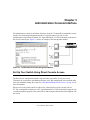
Set Up Your Switch Using Direct Console Access .........................................................3-1
Chapter 4
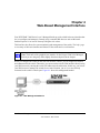
Web-Based Management Interface
Web Based Management Overview ...............................................................................4-2
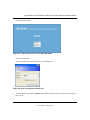
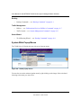
How to Log In to the Managed Switch ............................................................................4-2
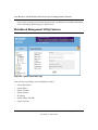
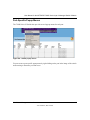
Web-Based Management Utility Features ......................................................................4-4
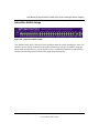
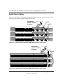
Interactive Switch Image ..........................................................................................4-5
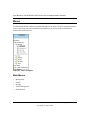
Menus .............................................................................................................................4-6
Main Menus ..............................................................................................................4-6
Secondary Menus ....................................................................................................4-7
Management ......................................................................................................4-7
Switch ................................................................................................................4-7
Routing ..............................................................................................................4-8
Traffic Management ...........................................................................................4-8
Smart Wizard .....................................................................................................4-8
System-Wide Popup Menus .....................................................................................4-8
Port-Specific Popup Menus ......................................................................................4-9
Contents
v
202-10088-01, March 2005
Chapter 5
Command Line Interface Structure
CLI Command Format ....................................................................................................5-1
Command .................................................................................................................5-1
Parameters ...............................................................................................................5-2
Values ......................................................................................................................5-2
Conventions .............................................................................................................5-3
Annotations ..............................................................................................................5-4
Chapter 6
Quick Start up
Quick Starting the Switch ................................................................................................6-1
System Info and System Setup ......................................................................................6-2
Quick Start up Software Version Information ...........................................................6-2
Quick Start up Physical Port Data ............................................................................6-2
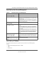
Quick Start up User Account Management ..............................................................6-3
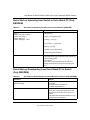
Quick Start up IP Address ........................................................................................6-3
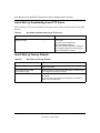
Quick Start up Uploading from Switch to Out-of-Band PC (Only XMODEM) ...........6-5
Quick Start up Downloading from Out-of-Band PC to Switch (Only XMODEM) ......6-5
Quick Start up Downloading from TFTP Server .......................................................6-6
Quick Start up Factory Defaults ...............................................................................6-6
Chapter 7
Mode-based CLI
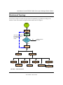
Mode-based Topology ....................................................................................................7-3
Mode-based Command Hierarchy ..................................................................................7-4
Flow of Operation ...........................................................................................................7-6
“No” Form of a Command ...............................................................................................7-7
Support for “No” Form ..............................................................................................7-7
Behavior of Command Help ("?") .............................................................................7-7
Chapter 8
Switching Commands
System Information and Statistics Commands ...............................................................8-1
show arp switch ........................................................................................................8-2
show eventlog ..........................................................................................................8-2
show hardware .........................................................................................................8-2
show interface ..........................................................................................................8-3
show interface ethernet ............................................................................................8-4
vi
Contents
202-10088-01, March 2005
show logging ..........................................................................................................8-13
show mac-addr-table ..............................................................................................8-13
show msglog ..........................................................................................................8-14
show running-config ...............................................................................................8-14
show sysinfo ...........................................................................................................8-15
snmp-server ...........................................................................................................8-15
System Management Commands ................................................................................8-15
telnet ......................................................................................................................8-16
transport input telnet ..............................................................................................8-16
no transport input telnet ...................................................................................8-16
transport output telnet ............................................................................................8-17
no transport output telnet .................................................................................8-17
session-limit ...........................................................................................................8-17
no session-limit ................................................................................................8-17
session-timeout ......................................................................................................8-17
no session-timeout ..........................................................................................8-18
bridge aging-time ...................................................................................................8-18
no bridge aging-time ........................................................................................8-18
mtu .........................................................................................................................8-19
no mtu ..............................................................................................................8-19
network javamode ..................................................................................................8-19
no network javamode ......................................................................................8-19
network mac-address .............................................................................................8-19
network mac-type ...................................................................................................8-20
no network mac-type .......................................................................................8-20
network parms ........................................................................................................8-20
network protocol .....................................................................................................8-21
telnetcon maxsessions ...........................................................................................8-21
no telnetcon maxsessions ...............................................................................8-21
telnetcon timeout ....................................................................................................8-21
no telnetcon timeout ........................................................................................8-22
serial baudrate .......................................................................................................8-22
no serial baudrate ............................................................................................8-22
serial timeout ..........................................................................................................8-22
no serial timeout ..............................................................................................8-22
Contents
vii
202-10088-01, March 2005
set prompt ..............................................................................................................8-23
serviceport ip ..........................................................................................................8-23
serviceport protocol ................................................................................................8-23
show telnet .............................................................................................................8-23
show forwardingdb agetime ...................................................................................8-24
show network .........................................................................................................8-24
show telnetcon .......................................................................................................8-25
show serial .............................................................................................................8-26
show serviceport ....................................................................................................8-26
SNMP Community Commands .....................................................................................8-27
show snmpcommunity ............................................................................................8-27
show snmptrap .......................................................................................................8-28
show trapflags ........................................................................................................8-28
snmp-server community .........................................................................................8-29
no snmp-server community .............................................................................8-29
snmp-server community ipaddr ..............................................................................8-30
no snmp-server community ipaddr ..................................................................8-30
snmp-server community ipmask ............................................................................8-30
no snmp-server community ipmask .................................................................8-30
snmp-server community mode ...............................................................................8-31
no snmp-server community mode ...................................................................8-31
snmp-server community ro .....................................................................................8-31
snmp-server community rw ....................................................................................8-31
snmp-server enable traps ......................................................................................8-32
no snmp-server enable traps ...........................................................................8-32
snmp-server enable traps bcaststorm ....................................................................8-32
no snmp-server enable traps bcaststorm ........................................................8-32
snmp-server enable traps linkmode .......................................................................8-32
no snmp-server enable traps linkmode ............................................................8-33
snmp-server enable traps multiusers .....................................................................8-33
no snmp-server enable traps multiusers ..........................................................8-33
snmp-server enable traps stpmode ........................................................................8-33
no snmp-server enable traps stpmode ............................................................8-33
snmptrap ................................................................................................................8-34
no snmptrap .....................................................................................................8-34
viii
Contents
202-10088-01, March 2005
snmptrap ipaddr .....................................................................................................8-34
snmptrap mode ......................................................................................................8-34
no snmptrap mode ...........................................................................................8-34
snmp trap link-status ..............................................................................................8-35
no snmp trap link-status ..................................................................................8-35
snmp trap link-status all .........................................................................................8-35
no snmp trap link-status all ..............................................................................8-35
Management VLAN Command .....................................................................................8-36
network mgmt_vlan ................................................................................................8-36
System Configuration Commands ................................................................................8-36
addport ...................................................................................................................8-36
auto-negotiate ........................................................................................................8-36
no auto-negotiate .............................................................................................8-37
auto-negotiate all ....................................................................................................8-37
no auto-negotiate all ........................................................................................8-37
deleteport (Interface Config) ..................................................................................8-37
deleteport (Global Config) ......................................................................................8-37
macfilter ..................................................................................................................8-38
no macfilter ......................................................................................................8-38
macfilter adddest ....................................................................................................8-38
no macfilter adddest ........................................................................................8-39
macfilter adddest all ...............................................................................................8-39
no macfilter adddest all ....................................................................................8-39
macfilter addsrc ......................................................................................................8-39
no macfilter addsrc ..........................................................................................8-40
macfilter addsrc all .................................................................................................8-40
no macfilter addsrc all ......................................................................................8-40
monitor session ......................................................................................................8-40
no monitor session ..........................................................................................8-41
monitor session mode ............................................................................................8-41
no monitor session mode ................................................................................8-41
shutdown ................................................................................................................8-41
no shutdown ....................................................................................................8-42
shutdown all ...........................................................................................................8-42
no shutdown all ................................................................................................8-42
Contents
ix
202-10088-01, March 2005
speed .....................................................................................................................8-42
speed all .................................................................................................................8-42
storm-control broadcast .........................................................................................8-43
no storm-control broadcast ..............................................................................8-43
storm-control flowcontrol ........................................................................................8-44
no storm-control flowcontrol ............................................................................8-44
show mac-address-table multicast .........................................................................8-44
show mac-address-table static ...............................................................................8-45
show mac-address-table staticfiltering ...................................................................8-45
show mac-address-table stats ...............................................................................8-46
show monitor ..........................................................................................................8-46
show port ................................................................................................................8-46
show port protocol ..................................................................................................8-47
show storm-control .................................................................................................8-48
Virtual LAN (VLAN) Commands ...................................................................................8-48
vlan .........................................................................................................................8-48
no vlan .............................................................................................................8-48
vlan acceptframe ....................................................................................................8-49
no vlan acceptframe ........................................................................................8-49
vlan ingressfilter .....................................................................................................8-49
no vlan ingressfilter ..........................................................................................8-49
vlan makestatic ......................................................................................................8-50
vlan name ...............................................................................................................8-50
no vlan name ...................................................................................................8-50
vlan participation ....................................................................................................8-50
vlan participation all ................................................................................................8-51
vlan port acceptframe all ........................................................................................8-51
no vlan port acceptframe all ............................................................................8-52
vlan port ingressfilter all .........................................................................................8-52
no vlan port ingressfilter all ..............................................................................8-52
vlan port pvid all .....................................................................................................8-52
no vlan port pvid all ..........................................................................................8-52
vlan port tagging all ................................................................................................8-53
no vlan port tagging all ....................................................................................8-53
vlan protocol group .................................................................................................8-53
x
Contents
202-10088-01, March 2005
vlan protocol group add protocol ............................................................................8-53
no vlan protocol group add protocol ................................................................8-54
vlan protocol group remove ....................................................................................8-54
protocol group ........................................................................................................8-54
no protocol group .............................................................................................8-54
protocol vlan group .................................................................................................8-55
no protocol vlan group .....................................................................................8-55
protocol vlan group all ............................................................................................8-55
no protocol vlan group all ................................................................................8-55
vlan pvid .................................................................................................................8-56
no vlan pvid .....................................................................................................8-56
vlan tagging ............................................................................................................8-56
no vlan tagging ................................................................................................8-56
show vlan ...............................................................................................................8-56
show vlan brief .......................................................................................................8-58
show vlan port ........................................................................................................8-58
System Utility Commands ............................................................................................8-59
traceroute ...............................................................................................................8-59
clear config .............................................................................................................8-60
clear counters .........................................................................................................8-60
clear igmpsnooping ................................................................................................8-60
clear pass ...............................................................................................................8-60
enable passwd .......................................................................................................8-60
clear port-channel ..................................................................................................8-61
clear traplog ...........................................................................................................8-61
clear vlan ................................................................................................................8-61
logout .....................................................................................................................8-61
ping ........................................................................................................................8-62
reload .....................................................................................................................8-62
copy ........................................................................................................................8-62
Pre-login Banner ...........................................................................................................8-63
copy ........................................................................................................................8-63
CLI Command Logging .................................................................................................8-64
logging cli-command ..............................................................................................8-64
no logging cli-command ...................................................................................8-64
Contents
xi
202-10088-01, March 2005
Configuration Scripting .................................................................................................8-64
configscript apply ...................................................................................................8-65
configscript delete ..................................................................................................8-65
configscript list ........................................................................................................8-65
configscript show ....................................................................................................8-65
configscript validate ................................................................................................8-66
show running-config ...............................................................................................8-66
System Log (Syslog) ....................................................................................................8-66
logging buffered .....................................................................................................8-67
no logging buffered ..........................................................................................8-67
logging buffered wrap .............................................................................................8-67
no logging wrap ...............................................................................................8-67
logging console ......................................................................................................8-67
no logging console ...........................................................................................8-68
logging history ........................................................................................................8-68
no logging history ............................................................................................8-68
logging host ............................................................................................................8-68
logging host remove ...............................................................................................8-69
logging port ............................................................................................................8-69
no logging port .................................................................................................8-69
logging syslog ........................................................................................................8-69
no logging syslog .............................................................................................8-69
show logging ..........................................................................................................8-70
show logging history ...............................................................................................8-70
show logging buffered ............................................................................................8-71
show logging hosts .................................................................................................8-71
Simple Network Time Protocol (SNTP) ........................................................................8-72
sntp broadcast client poll-interval ...........................................................................8-72
no sntp broadcast client poll-interval ...............................................................8-72
sntp client mode .....................................................................................................8-72
sntp client mode ..............................................................................................8-73
sntp client port ........................................................................................................8-73
no sntp client port ............................................................................................8-73
sntp unicast client poll-interval ...............................................................................8-73
no sntp unicast client poll-interval ....................................................................8-73
xii
Contents
202-10088-01, March 2005
sntp unicast client poll-timeout ...............................................................................8-74
no sntp unicast client poll-timeout ...................................................................8-74
sntp unicast client poll-retry ....................................................................................8-74
no sntp unicast client poll-retry ........................................................................8-74
sntp multicast client poll-interval ............................................................................8-74
no sntp multicast client poll-interval .................................................................8-75
sntp server .............................................................................................................8-75
no sntp server ..................................................................................................8-75
show sntp ...............................................................................................................8-75
show sntp client ......................................................................................................8-76
show sntp server ....................................................................................................8-76
User Account Commands .............................................................................................8-77
disconnect ..............................................................................................................8-77
show loginsession ..................................................................................................8-77
show users .............................................................................................................8-78
users name ............................................................................................................8-79
no users name .................................................................................................8-79
users passwd .........................................................................................................8-79
no users passwd ..............................................................................................8-79
users snmpv3 accessmode ....................................................................................8-80
no users snmpv3 accessmode ........................................................................8-80
users snmpv3 authentication .................................................................................8-80
no users snmpv3 authentication ......................................................................8-80
users snmpv3 encryption .......................................................................................8-81
no users snmpv3 encryption ............................................................................8-81
DHCP Server Commands ............................................................................................8-81
client-identifier ........................................................................................................8-82
no client-identifier ............................................................................................8-82
client-name .............................................................................................................8-82
no client-name .................................................................................................8-82
default-router ..........................................................................................................8-83
no default-router ..............................................................................................8-83
dns-server ..............................................................................................................8-83
no dns-server ...................................................................................................8-83
hardware-address ..................................................................................................8-83
Contents
xiii
202-10088-01, March 2005
no hardware-address .......................................................................................8-84
host ........................................................................................................................8-84
no host .............................................................................................................8-84
ip dhcp excluded-address ......................................................................................8-84
no ip dhcp excluded-address ...........................................................................8-85
ip dhcp ping packets ..............................................................................................8-85
no ip dhcp ping packets ...................................................................................8-85
ip dhcp pool ............................................................................................................8-85
no ip dhcp pool ................................................................................................8-86
lease .......................................................................................................................8-86
no lease ...........................................................................................................8-86
network ...................................................................................................................8-86
no network .......................................................................................................8-87
service dhcp ...........................................................................................................8-87
no service dhcp ...............................................................................................8-87
bootfile ....................................................................................................................8-87
no bootfile ........................................................................................................8-87
domain-name .........................................................................................................8-88
no domain-name ..............................................................................................8-88
ip dhcp bootp automatic .........................................................................................8-88
no ip dhcp bootp automatic .............................................................................8-88
ip dhcp conflict logging ...........................................................................................8-88
no ip dhcp conflict logging ...............................................................................8-89
netbios-name-server ..............................................................................................8-89
no netbios-name-server ...................................................................................8-89
netbios-node-type ..................................................................................................8-89
no netbios-node-type .......................................................................................8-90
next-server .............................................................................................................8-90
no next-server ..................................................................................................8-90
option .....................................................................................................................8-90
no option ..........................................................................................................8-91
show ip dhcp binding ..............................................................................................8-91
show ip dhcp global configuration ..........................................................................8-91
show ip dhcp pool configuration .............................................................................8-92
show ip dhcp server statistics ................................................................................8-92
xiv
Contents
202-10088-01, March 2005
show ip dhcp conflict ..............................................................................................8-93
clear ip dhcp binding ..............................................................................................8-94
clear ip dhcp server statistics .................................................................................8-94
clear ip dhcp conflict ...............................................................................................8-94
Provisioning (IEEE 802.1p) Commands .......................................................................8-94
classofservice dot1pmapping .................................................................................8-95
show classofservice dot1pmapping .......................................................................8-95
vlan port priority all .................................................................................................8-95
vlan priority .............................................................................................................8-95
GARP Commands ........................................................................................................8-96
set garp timer join ...................................................................................................8-96
no set garp timer join .......................................................................................8-96
set garp timer join all ..............................................................................................8-97
no set garp timer join all ..................................................................................8-97
set garp timer leave ................................................................................................8-97
no set garp timer leave ....................................................................................8-97
set garp timer leave all ...........................................................................................8-98
no set garp timer leave all ...............................................................................8-98
set garp timer leaveall ............................................................................................8-98
no set garp timer leaveall ................................................................................8-98
set garp timer leaveall all .......................................................................................8-99
no set garp timer leaveall all ............................................................................8-99
show garp ...............................................................................................................8-99
GARP VLAN Registration Protocol (GVRP) Commands ............................................8-100
set gvrp adminmode .............................................................................................8-100
no set gvrp adminmode .................................................................................8-100
set gvrp interfacemode .........................................................................................8-100
no set gvrp interfacemode .............................................................................8-100
set gvrp interfacemode all ....................................................................................8-101
no set gvrp interfacemode all ........................................................................8-101
show gvrp configuration .......................................................................................8-101
GARP Multicast Registration Protocol (GMRP) Commands ......................................8-102
set gmrp adminmode ...........................................................................................8-102
no set gmrp adminmode ................................................................................8-102
set gmrp interfacemode .......................................................................................8-103
Contents
xv
202-10088-01, March 2005
no set gmrp interfacemode ............................................................................8-103
set gmrp interfacemode all ...................................................................................8-103
no set gmrp interfacemode all .......................................................................8-103
show gmrp configuration ......................................................................................8-104
show mac-address-table gmrp .............................................................................8-104
Internet Group Management Protocol (IGMP) Commands ........................................8-105
set igmp ................................................................................................................8-105
no set igmp ....................................................................................................8-106
set igmp ................................................................................................................8-106
no set igmp ....................................................................................................8-106
set igmp groupmembership-interval .....................................................................8-106
no set igmp groupmembership-interval .........................................................8-106
set igmp interfacemode all ...................................................................................8-107
no set igmp interfacemode all ........................................................................8-107
set igmp maxresponse .........................................................................................8-107
no set igmp maxresponse .............................................................................8-107
set igmp mcrtrexpiretime ......................................................................................8-108
no set igmp mcrtrexpiretime ..........................................................................8-108
show igmpsnooping .............................................................................................8-108
show mac-address-table igmpsnooping ...............................................................8-109
IGMP Snooping per VLAN ..........................................................................................8-109
set igmp ................................................................................................................8-109
no set igmp .................................................................................................... 8-110
set igmp groupmembershipinterval ...................................................................... 8-110
no set igmp groupmembershipinterval .......................................................... 8-110
set igmp maxresponse ......................................................................................... 8-110
no set igmp maxresponse ............................................................................. 8-111
set igmp mcrtexpiretime ....................................................................................... 8-111
no set igmp mcrtexpiretime ........................................................................... 8-111
set igmp fast-leave ............................................................................................... 8-111
no set igmp fast-leave ................................................................................... 8-112
show igmpsnooping ............................................................................................. 8-112
Link Aggregation (LAG)/Port-Channel (802.3AD) Commands ................................... 8-113
port-channel staticcapability ................................................................................. 8-113
no port-channel staticcapability ..................................................................... 8-114
xvi
Contents
202-10088-01, March 2005
port lacpmode ...................................................................................................... 8-114
no port lacpmode ........................................................................................... 8-114
port lacpmode all .................................................................................................. 8-114
no port lacpmode all ...................................................................................... 8-114
port-channel ......................................................................................................... 8-115
no port-channel .............................................................................................. 8-115
port-channel adminmode all ................................................................................. 8-115
no port-channel adminmode .......................................................................... 8-115
port-channel linktrap ............................................................................................. 8-115
no port-channel linktrap ................................................................................. 8-116
port-channel name ............................................................................................... 8-116
show port-channel brief ........................................................................................ 8-116
show port-channel ................................................................................................ 8-117
Spanning Tree (STP) Commands ............................................................................... 8-118
spanning-tree max-hops ...................................................................................... 8-118
no spanning-tree max-hops ........................................................................... 8-118
spanning-tree ....................................................................................................... 8-118
no spanning-tree ............................................................................................ 8-119
spanning-tree configuration name ........................................................................ 8-119
no spanning-tree configuration name ............................................................ 8-119
spanning-tree configuration revision .................................................................... 8-119
no spanning-tree configuration revision .........................................................8-120
spanning-tree edgeport ........................................................................................8-120
no spanning-tree edgeport ............................................................................8-120
spanning-tree forceversion ...................................................................................8-120
no spanning-tree forceversion .......................................................................8-121
spanning-tree forward-time ..................................................................................8-121
no spanning-tree forward-time .......................................................................8-121
spanning-tree hello-time .......................................................................................8-121
no spanning-tree hello-time ...........................................................................8-121
spanning-tree max-age ........................................................................................8-122
no spanning-tree max-age .............................................................................8-122
spanning-tree mst ................................................................................................8-122
no spanning-tree mst .....................................................................................8-123
spanning-tree mst instance ..................................................................................8-124
Contents
xvii
202-10088-01, March 2005
no spanning-tree mst instance .......................................................................8-124
spanning-tree mst priority .....................................................................................8-124
no spanning-tree mst priority .........................................................................8-124
spanning-tree mst vlan .........................................................................................8-125
no spanning-tree mst vlan .............................................................................8-125
spanning-tree port mode ......................................................................................8-125
no spanning-tree port mode ..........................................................................8-125
spanning-tree port mode all .................................................................................8-126
no spanning-tree port mode all ......................................................................8-126
spanning-tree .......................................................................................................8-126
spanning-tree bpdumigrationcheck ......................................................................8-126
no spanning-tree bpdumigrationcheck ...........................................................8-127
show spanning-tree ..............................................................................................8-127
show spanning-tree interface ...............................................................................8-128
show spanning-tree mst detailed .........................................................................8-129
show spanning-tree mst port detailed ..................................................................8-129
show spanning-tree mst port summary ................................................................8-131
show spanning-tree mst summary .......................................................................8-131
show spanning-tree summary ..............................................................................8-132
show spanning-tree vlan ......................................................................................8-132
spanning-tree max-hops ......................................................................................8-133
no spanning-tree max-hops ...........................................................................8-133
spanning-tree mst ................................................................................................8-133
no spanning-tree mst .....................................................................................8-134
spanning-tree hello-time .......................................................................................8-134
no spanning-tree hello-time ...........................................................................8-135
show spanning-tree ..............................................................................................8-135
show spanning-tree interface ...............................................................................8-136
show spanning-tree mst port detailed ..................................................................8-137
Chapter 9
Security Commands
Port Security ...................................................................................................................9-1
port-security .............................................................................................................9-1
no port-security ..................................................................................................9-1
port-security max-dynamic .......................................................................................9-2
xviii
Contents
202-10088-01, March 2005
no port-security max-dynamic ...........................................................................9-2
port-security max-static ............................................................................................9-2
no port-security max-static .................................................................................9-2
port-security mac-address ........................................................................................9-3
no port-security mac-address ............................................................................9-3
port-security mac-address move ..............................................................................9-3
snmp-server enable traps violation ..........................................................................9-3
no snmp-server enable traps violation ...............................................................9-3
show port-security ....................................................................................................9-4
show port-security ....................................................................................................9-4
show port-security dynamic ......................................................................................9-4
show port-security static ...........................................................................................9-4
show port-security violation ......................................................................................9-5
Port Based Network Access Control (IEEE 802.1X) Commands ...................................9-5
authentication login ..................................................................................................9-5
no authentication login .......................................................................................9-6
clear dot1x statistics .................................................................................................9-6
clear radius statistics ................................................................................................9-6
dot1x defaultlogin .....................................................................................................9-6
dot1x initialize ...........................................................................................................9-7
dot1x login ................................................................................................................9-7
dot1x max-req ..........................................................................................................9-7
no dot1x max-req ...............................................................................................9-7
dot1x port-control .....................................................................................................9-8
no dot1x port-control ..........................................................................................9-8
dot1x port-control All ................................................................................................9-8
no dot1x port-control All .....................................................................................9-9
dot1x re-authenticate ...............................................................................................9-9
dot1x re-authentication .............................................................................................9-9
no dot1x re-authentication .................................................................................9-9
dot1x system-auth-control ........................................................................................9-9
no dot1x system-auth-control ..........................................................................9-10
dot1x timeout ..........................................................................................................9-10
no dot1x timeout .............................................................................................. 9-11
dot1x user .............................................................................................................. 9-11
Contents
xix
202-10088-01, March 2005
no dot1x user ................................................................................................... 9-11
show radius accounting .......................................................................................... 9-11
show authentication ...............................................................................................9-12
show authentication users ......................................................................................9-13
show dot1x .............................................................................................................9-13
show dot1x users ...................................................................................................9-16
show users authentication ......................................................................................9-16
users defaultlogin ...................................................................................................9-16
users login ..............................................................................................................9-16
Remote Authentication Dial In User Service (RADIUS) Commands ............................9-17
radius accounting mode .........................................................................................9-17
no radius accounting mode .............................................................................9-17
radius server host ...................................................................................................9-17
no radius server host .......................................................................................9-18
radius server key ....................................................................................................9-19
radius server msgauth ............................................................................................9-19
radius server primary .............................................................................................9-19
radius server retransmit .........................................................................................9-19
no radius server retransmit ..............................................................................9-20
radius server timeout ..............................................................................................9-20
no radius server timeout ..................................................................................9-20
show radius ............................................................................................................9-20
show radius statistics .............................................................................................9-21
Secure Shell (SSH) Commands ...................................................................................9-22
ip ssh ......................................................................................................................9-22
no ip ssh ..........................................................................................................9-23
ip ssh protocol ........................................................................................................9-23
show ip ssh ............................................................................................................9-23
Hypertext Transfer Protocol (HTTP) Commands ..........................................................9-23
ip http secure-port ..................................................................................................9-24
no ip http secure-port .......................................................................................9-24
ip http secure-protocol ............................................................................................9-24
ip http secure-server ..............................................................................................9-24
no ip http secure-server ...................................................................................9-24
ip http server ..........................................................................................................9-25
xx
Contents
202-10088-01, March 2005
no ip http server ...............................................................................................9-25
show ip http ............................................................................................................9-25
Chapter 10
Routing Commands
Address Resolution Protocol (ARP) Commands ..........................................................10-1
arp ..........................................................................................................................10-1
no arp ..............................................................................................................10-1
ip proxy-arp ............................................................................................................10-2
no ip proxy-arp .................................................................................................10-2
arp cachesize .........................................................................................................10-2
no arp cachesize .............................................................................................10-2
arp dynamicrenew ..................................................................................................10-3
no arp dynamicrenew ......................................................................................10-3
arp purge ................................................................................................................10-3
arp resptime ...........................................................................................................10-3
no arp resptime ................................................................................................10-3
arp retries ...............................................................................................................10-4
no arp retries ...................................................................................................10-4
arp timeout .............................................................................................................10-4
no arp timeout ..................................................................................................10-4
clear arp-cache ......................................................................................................10-4
show arp .................................................................................................................10-5
show arp brief .........................................................................................................10-6
IP Routing .....................................................................................................................10-6
routing ....................................................................................................................10-6
no routing .........................................................................................................10-7
ip routing ................................................................................................................10-7
no ip routing .....................................................................................................10-7
ip address ...............................................................................................................10-7
no ip address ...................................................................................................10-8
ip route ...................................................................................................................10-8
no ip route ........................................................................................................10-8
ip route default .......................................................................................................10-8
no ip route default ............................................................................................10-9
ip route distance .....................................................................................................10-9
Contents
xxi
202-10088-01, March 2005
no ip route distance .........................................................................................10-9
ip forwarding ...........................................................................................................10-9
no ip forwarding .............................................................................................10-10
ip netdirbcast ........................................................................................................10-10
no ip netdirbcast ............................................................................................10-10
ip mtu ...................................................................................................................10-10
no ip mtu ........................................................................................................10-10
show ip brief ......................................................................................................... 10-11
show ip interface .................................................................................................. 10-11
show ip interface brief ..........................................................................................10-12
show ip route ........................................................................................................10-12
show ip route bestroutes ......................................................................................10-13
show ip route entry ...............................................................................................10-13
show ip route preferences ....................................................................................10-14
show ip stats ........................................................................................................10-14
encapsulation .......................................................................................................10-15
Bootp/DHCP Relay Commands .................................................................................10-15
bootpdhcprelay cidoptmode .................................................................................10-15
no bootpdhcprelay cidoptmode .....................................................................10-15
bootpdhcprelay enable .........................................................................................10-16
no bootpdhcprelay enable .............................................................................10-16
bootpdhcprelay maxhopcount ..............................................................................10-16
no bootpdhcprelay maxhopcount ..................................................................10-16
bootpdhcprelay minwaittime .................................................................................10-16
no bootpdhcprelay minwaittime .....................................................................10-17
bootpdhcprelay serverip .......................................................................................10-17
no bootpdhcprelay serverip ...........................................................................10-17
show bootpdhcprelay ...........................................................................................10-17
Router Discovery Protocol Commands ......................................................................10-18
ip irdp ...................................................................................................................10-18
no ip irdp ........................................................................................................10-18
ip irdp address ......................................................................................................10-18
no ip irdp address ..........................................................................................10-19
ip irdp holdtime .....................................................................................................10-19
no ip irdp holdtime .........................................................................................10-19
xxii
Contents
202-10088-01, March 2005
ip irdp maxadvertinterval ......................................................................................10-19
no ip irdp maxadvertinterval ...........................................................................10-19
ip irdp minadvertinterval .......................................................................................10-20
no ip irdp minadvertinterval ............................................................................10-20
ip irdp preference .................................................................................................10-20
no ip irdp preference ......................................................................................10-20
show ip irdp ..........................................................................................................10-20
Virtual LAN Routing Commands .................................................................................10-21
vlan routing ...........................................................................................................10-21
no vlan routing ...............................................................................................10-21
show ip vlan .........................................................................................................10-22
Routing Information Protocol (RIP) Commands .........................................................10-22
enable (RIP) .........................................................................................................10-22
no enable (RIP) .............................................................................................10-23
ip rip .....................................................................................................................10-23
no ip rip ..........................................................................................................10-23
auto-summary ......................................................................................................10-23
no auto-summary ...........................................................................................10-23
default-information originate (RIP) .......................................................................10-23
no default-information originate (RIP) ............................................................10-24
default-metric (RIP) ..............................................................................................10-24
no default-metric (RIP) ..................................................................................10-24
distance rip ...........................................................................................................10-24
no distance rip ...............................................................................................10-24
distribute-list out ...................................................................................................10-25
no distribute-list out .......................................................................................10-25
no default-information originate .....................................................................10-25
ip rip authentication ..............................................................................................10-25
no ip rip authentication ..................................................................................10-26
ip rip receive version ............................................................................................10-26
no ip rip receive version .................................................................................10-26
ip rip send version ................................................................................................10-26
no ip rip send version ....................................................................................10-27
hostroutesaccept ..................................................................................................10-27
no hostroutesaccept ......................................................................................10-27
Contents
xxiii
202-10088-01, March 2005
split-horizon ..........................................................................................................10-27
no split-horizon ..............................................................................................10-27
redistribute ...........................................................................................................10-28
no redistribute ................................................................................................10-28
show ip rip ............................................................................................................10-28
show ip rip interface brief .....................................................................................10-29
show ip rip interface .............................................................................................10-30
Chapter 11
Quality of Service (QoS) Commands
Access Control List (ACL) Commands ......................................................................... 11-1
mac access-list extended <name> ......................................................................... 11-1
no mac access-list extended <name> ............................................................. 11-2
mac access-list extended rename <name> <newname> ....................................... 11-2
{deny|permit} <srcmac> <srcmacmask> <dstmac> <dstmacmask> ...................... 11-2
mac access-group <name> {in|out} [sequence <1-4294967295>] ........................ 11-3
no mac access-group <name> {in|out} ............................................................ 11-4
show mac access-list <name> ............................................................................... 11-4
show mac access-lists ........................................................................................... 11-4
access-list .............................................................................................................. 11-5
no access-list ................................................................................................... 11-6
ip access-group ...................................................................................................... 11-6
ip access-group all ................................................................................................. 11-6
show ip access-lists ............................................................................................... 11-6
Differentiated Services (DiffServ) Commands .............................................................. 11-7
diffserv .................................................................................................................... 11-8
no diffserv ........................................................................................................ 11-9
Class Commands ................................................................................................... 11-9
class-map ........................................................................................................ 11-9
class-map rename ......................................................................................... 11-11
match ethertype ............................................................................................. 11-11
match secondary-cos .................................................................................... 11-11
match secondary-vlan ................................................................................... 11-11
match any ...................................................................................................... 11-12
match class-map ........................................................................................... 11-12
match cos ...................................................................................................... 11-13
xxiv
Contents
202-10088-01, March 2005
match destination-address mac ..................................................................... 11-13
match dstip .................................................................................................... 11-14
match dstl4port .............................................................................................. 11-14
match ip dscp ................................................................................................ 11-15
match ip precedence ..................................................................................... 11-15
match ip tos ................................................................................................... 11-16
match protocol ............................................................................................... 11-16
match source-address mac ........................................................................... 11-17
match srcip .................................................................................................... 11-17
match srcl4port .............................................................................................. 11-17
match vlan ..................................................................................................... 11-18
Policy Commands ................................................................................................ 11-18
assign-queue ................................................................................................. 11-19
drop ............................................................................................................... 11-19
mark secondary-cos ...................................................................................... 11-19
redirect ........................................................................................................... 11-20
conform-color ................................................................................................. 11-20
bandwidth kbps .............................................................................................. 11-20
bandwidth percent ......................................................................................... 11-21
class .............................................................................................................. 11-21
expedite kbps ................................................................................................ 11-22
expedite percent ............................................................................................ 11-22
mark cos ........................................................................................................ 11-23
mark ip-dscp .................................................................................................. 11-23
mark ip-precedence ....................................................................................... 11-24
police-simple .................................................................................................. 11-24
police-single-rate ........................................................................................... 11-25
police-two-rate ............................................................................................... 11-26
policy-map ..................................................................................................... 11-27
policy-map rename ........................................................................................ 11-27
randomdrop ................................................................................................... 11-27
shape average ............................................................................................... 11-28
shape peak .................................................................................................... 11-28
Service Commands .............................................................................................. 11-29
service-policy ................................................................................................. 11-29
Contents
xxv
202-10088-01, March 2005
Show Commands ................................................................................................. 11-30
show class-map ............................................................................................. 11-31
show diffserv .................................................................................................. 11-32
show policy-map ............................................................................................ 11-33
show diffserv service ..................................................................................... 11-36
show diffserv service brief ............................................................................. 11-37
show policy-map interface ............................................................................. 11-37
show service-policy ....................................................................................... 11-39
Class of Service (CoS) Commands ............................................................................ 11-40
classofservice dot1p-mapping .............................................................................. 11-40
classofservice ip-dscp-mapping ........................................................................... 11-40
classofservice ip-precedence-mapping ................................................................ 11-41
classofservice trust ............................................................................................... 11-41
no classofservice trust ................................................................................... 11-41
cos-queue max-bandwidth ................................................................................... 11-41
no cos-queue max-bandwidth .............................................................................. 11-42
cos-queue min-bandwidth .................................................................................... 11-42
no cos-queue min-bandwidth ........................................................................ 11-42
cos-queue random-detect .................................................................................... 11-42
no cos-queue random-detect ......................................................................... 11-42
cos-queue strict .................................................................................................... 11-43
no cos-queue strict ........................................................................................ 11-43
random-detect ...................................................................................................... 11-43
no random-detect .......................................................................................... 11-43
random-detect exponential-weighting-constant ................................................... 11-44
no random-detect exponential-weighting-constant ........................................ 11-44
random-detect queue-parms ................................................................................ 11-44
no random-detect queue-parms .................................................................... 11-44
tail-drop queue-parms .......................................................................................... 11-44
traffic-shape ......................................................................................................... 11-45
show classofservice dot1p-mapping .................................................................... 11-45
show classofservice ip-precedence-mapping ...................................................... 11-46
show classofservice trust ..................................................................................... 11-46
show interfaces cos-queue .................................................................................. 11-46
show interfaces random-detect ............................................................................ 11-47
xxvi
Contents
202-10088-01, March 2005
show interfaces tail-drop-threshold ...................................................................... 11-48
Chapter 12
Managing Switch Stacks
Understanding Switch Stacks .......................................................................................12-1
Switch Stack Membership ......................................................................................12-2
Switch Stack Cabling ..............................................................................................12-4
Stack Master Election and Re-Election ..................................................................12-5
Stack Member Numbers .........................................................................................12-5
Stack Member Priority Values ................................................................................12-6
Switch Stack Offline Configuration .........................................................................12-6
Effects of Adding a Preconfigured Switch to a Switched Stack .......................12-6
Effects of Replacing a Preconfigured Switch in a Switch Stack .............................12-7
Effects of Removing a Preconfigured Switch from a Switch Stack ........................12-7
Switch Stack Software Compatibility Recommendations ..............................................12-8
Incompatible Software and Stack Member Image Upgrades ........................................12-8
Switch Stack Configuration Files ..................................................................................12-8
Switch Stack Management Connectivity .......................................................................12-9
Connectivity to the Switch Stack Through Console Ports ......................................12-9
Connectivity to the Switch Stack Through Telnet ...................................................12-9
Switch Stack Configuration Scenarios ..........................................................................12-9
Stacking Recommendations .......................................................................................12-10
General Practices ................................................................................................. 12-11
Initial installation and Power-up of a Stack ........................................................... 12-11
Removing a Unit from the Stack ...........................................................................12-12
Adding a Unit to an Operating Stack ....................................................................12-12
Replacing a Stack Member with a New Unit ........................................................12-12
Renumbering Stack Members ..............................................................................12-13
Moving a Master to a Different Unit in the Stack ..................................................12-14
Removing a Master Unit from an Operating Stack ...............................................12-14
Merging Two Operational Stacks .........................................................................12-14
Preconfiguration ...................................................................................................12-15
Upgrading Firmware .............................................................................................12-15
Migration of Configuration With a Firmware Upgrade ..........................................12-16
Code Mismatch ....................................................................................................12-16
Contents
xxvii
202-10088-01, March 2005
Appendix A
IS CLI Mapping
Appendix B
Cabling Guidelines
Fast Ethernet Cable Guidelines ..................................................................................... B-1
Category 5 Cable ........................................................................................................... B-2
Category 5 Cable Specifications ............................................................................. B-2
Twisted Pair Cables ................................................................................................ B-3
Patch Panels and Cables ........................................................................................ B-4
Using 1000BASE-T Gigabit Ethernet over Category 5 Cable ....................................... B-5
Cabling .................................................................................................................... B-5
Near End Cross Talk (NEXT) .................................................................................. B-6
Patch Cables ........................................................................................................... B-6
RJ-45 Plug and RJ-45 Connectors ......................................................................... B-6
Conclusion .............................................................................................................. B-8
Appendix C
Glossary
Numeric ......................................................................................................................... C-1
A .................................................................................................................................... C-2
B .................................................................................................................................... C-3
C .................................................................................................................................... C-4
D .................................................................................................................................... C-5
E .................................................................................................................................... C-6
F .................................................................................................................................... C-7
G .................................................................................................................................... C-8
H .................................................................................................................................... C-9
I ...................................................................................................................................... C-9
L ................................................................................................................................... C-11
M .................................................................................................................................. C-12
N .................................................................................................................................. C-14
O .................................................................................................................................. C-14
P .................................................................................................................................. C-15
Q .................................................................................................................................. C-16
R .................................................................................................................................. C-17
S .................................................................................................................................. C-18
xxviii
Contents
202-10088-01, March 2005
T .................................................................................................................................. C-19
U .................................................................................................................................. C-20
V .................................................................................................................................. C-20
W ................................................................................................................................. C-21
X .................................................................................................................................. C-22
Contents
xxix
202-10088-01, March 2005
xxx
Contents
202-10088-01, March 2005
Chapter 1
About This Guide
Thank you for purchasing the NETGEAR™ 7300S Series L3 Switch.
Audience
This reference manual assumes that the reader has basic-to-intermediate computer and Internet
skills. However, basic computer network, Internet, and wireless technology tutorial information is
provided in the Appendices.
This document describes configuration commands for the 7300S Series L3 Switch software. The
commands can be accessed from the CLI, telnet, and Web interfaces.
Why the Document was Created
This document was created primarily for system administrators configuring and operating a
system using 7300S Series L3 Switch software. It is intended to provide an understanding of the
configuration options of 7300S Series L3 Switch software.
It is assumed that the reader has an understanding of the relevant switch platforms. It is also
assumed that the reader has a basic knowledge of Ethernet and networking concepts.
How to Use This Document
This document describes configuration commands for the 7000 Series L3 Managed Switch
software. The commands can be accessed from the CLI, telnet, and Web interfaces.
•
Chapter 6, “Quick Start up” details the procedure to quickly become acquainted with the 7000
Series L3 Managed Switch Software.
•
Chapter 8, “Switching Commands” describes the Switching commands.
•
Chapter 9, “Security Commands” describes the Security commands.
About This Guide
1-1
202-10088-01, March 2005
User Manual for the NETGEAR 7300S Series Layer 3 Managed Switch Software
•
Chapter 10, “Routing Commands” describes the Routing commands.
•
Chapter 11, “Quality of Service (QoS) Commands” describes the QOS commands.
•
Chapter 12, “Managing Switch Stacks” describes the switch stacking.
Note: Refer to the release notes for the 7000 Series L3 Managed Switch Software application
level code. The release notes detail the platform specific functionality of the Switching, Routing,
SNMP, Config, Management, and Bandwidth Provisioning packages.
Typographical Conventions
This guide uses the following typographical conventions:
Table 1.
Typographical conventions
italics
Emphasis.
bold
User input.
[Enter]
Named keys in text are shown enclosed in square brackets. The notation [Enter]
is used for the Enter key and the Return key.
[Ctrl]+C
Two or more keys that must be pressed simultaneously are shown in text linked
with a plus (+) sign.
SMALL CAPS
DOS file and directory names.
Special Message Formats
This guide uses the following formats to highlight special messages:
Note: This format is used to highlight information of importance or special interest.
This manual is written for the 7300S Series L3 Switch according to these specifications:
Table 1-1.
Manual Specifications
Product Version
NETGEAR 7300S Series Layer 3 Managed Switch
Manual Publication Date
March 2005
1-2
About This Guide
202-10088-01, March 2005
User Manual for the NETGEAR 7300S Series Layer 3 Managed Switch Software
Note: Product updates are available on the NETGEAR, Inc. Web site at
http://www.netgear.com/support/main.asp.
About This Guide
1-3
202-10088-01, March 2005
User Manual for the NETGEAR 7300S Series Layer 3 Managed Switch Software
1-4
About This Guide
202-10088-01, March 2005
Chapter 2
Switch Management Overview
This chapter gives an overview of switch management, including the methods you can use to
manage your NETGEAR 7300S Series Layer 3 Managed Switch.
•
Management Access Overview
•
SNMP Access
•
Protocols
Scope
The NETGEAR 7300S Series Layer 3 Managed Switch software has two purposes:
•
Assist attached hardware in switching frames, based on Layer 2 or 3 information contained in
the frames.
•
Provide a complete switch management portfolio for the network administrator.
Switch Management Overview
Fast Ethernet (FEN) and Gigabit Ethernet (GEN) switching continues to evolve from high-end
backbone applications to desktop switching applications. The price of the technology continues to
decline, while performance and feature sets continue to improve. Devices that are capable of
switching Layers 2, 3, and 4 are increasingly in demand. The NETGEAR 7300S Series Layer 3
Managed Switch provides a flexible solution to these ever-increasing needs.
The NETGEAR 7300S Series Layer 3 Managed Switch provides the network administrator with a
set of comprehensive management functions for managing both the FSM7328S, FSM7352S and
the network. The network administrator has a choice of three easy-to-use management methods:
•
Web-based
•
VT100 interface
Note: The maximum number of configuration file command lines is 2000.
Switch Management Overview
2-1
202-10088-01, March 2005
User Manual for the NETGEAR 7300S Series Layer 3 Managed Switch Software
•
Simple Network Protocol Management (SNMP)
Each management method enables the network administrator to configure, manage, and control
the managed switch locally or remotely using in-band or out-of-band mechanisms. Management is
standards-based, with configuration parameters and a private MIB providing control for functions
not completely specified in the MIBs.
Table 2-1.
Comparing Switch Management Methods
Management Method
Advantages
Disadvantages
Administration
console
• Out-of-band access via direct cable
• Must be near switch or use dial-up
connection means network bottlenecks,
connection
crashes, and downtime do not slow or
• Not convenient for remote users
prevent access
• Not graphical
• No IP address or subnet needed
• CLI based
• HyperTerminal access to full functionality
(HyperTerminal is built into Microsoft
Windows 95/98/NT/2000/XP operating
systems)
• Secure – make sure the switch is installed
in a secure area.
Web browser
or Telnet
• Can be accessed from any location via the • May encounter lag times on poor
switch’s IP address
connections
• Ideal for configuring the switch remotely
• Displaying graphical objects over a
• Compatible with Internet Explorer and
browser interface may slow navigation
Netscape Navigator Web browsers
• Familiar browser interface
• Graphical data available
• Most visually appealing
• CLI interfaces available
• Can be secured via SSL or SSH
SNMP Agent
• Communicates with switch functions at the • Requires SNMP management
Management Information Base (MIB) level software
• Based on open standards
• Least visually appealing of all three
• Can be secured via SNMPv3
methods
• Limited amount of information
available
• Some settings require calculations
2-2
Switch Management Overview
202-10088-01, March 2005
Chapter 3
Administration Console Interface
The administration console is an internal, character-oriented, VT-100/ANSI command-driven user
interface for performing management activities. Using this method, you can view the
administration console from a terminal, PC, Apple Macintosh, or UNIX workstation connected to
the switch’s console port. Figure 3-1 shows an example of this management method.
Figure 3-1: Administration Console Management Method
Set Up Your Switch Using Direct Console Access
The direct access management method is required when you initially set up your switch.
Thereafter, the convenience and additional features of the Web management access method make
it the best method to manage the switch. See “Web Based Management Overview” on page 4-2 for
more information.
Direct access to the switch console is achieved by connecting the switch’s console port to a
VT-100 or compatible terminal or to a PC, Apple Macintosh, or UNIX workstation equipped with
a terminal-emulation program. This connection is made using the null-modem cable supplied with
the switch.
Administration Console Interface
3-1
202-10088-01, March 2005
User Manual for the NETGEAR 7300S Series Layer 3 Managed Switch Software
Examples of terminal-emulation programs include:
•
HyperTerminal, which is included with Microsoft Windows operating systems
•
ZTerm for the Apple Macintosh
•
TIP for UNIX workstations
This example describes how to set up the connection using a HyperTerminal on a PC, but other
systems follow similar steps.
1.
Click the Windows Start button. Select Accessories and then Communications. HyperTerminal
should be one of the options listed in this menu. Select HyperTerminal
2.
The following screen will appear. Enter a name for this connection. In the example below, the
name of the connection is FSM726. Click OK.
Figure 3-2: Connection Description
3.
The following screen will appear. In the bottom, drop down box labeled Connect Using:, click
the arrow and choose the COM port to which the switch will connect. In the example below,
COM1 is the port selected. Click OK.
Figure 3-3: COM Port Selection
3-2
Administration Console Interface
202-10088-01, March 2005
User Manual for the NETGEAR 7300S Series Layer 3 Managed Switch Software
4.
When the following screen appears, make sure that the port setting are as follows:
Baud Rate:
Data Bits:
Parity:
Stop Bits:
Flow Control:
9600
8
None
1
None
Figure 3-4: Connection Settings
5.
Click OK.
The HyperTerminal window will open and you should be connected to the switch. If you do not
get a welcome screen or a system menu, press the return key.
When attached to the User Interface via a console connection, the following must be set in order to
use the arrow keys: Under the terminal pull down menu, choose Properties and make sure the
VT100 Arrows option is turned on.
Administration Console Interface
3-3
202-10088-01, March 2005
User Manual for the NETGEAR 7300S Series Layer 3 Managed Switch Software
3-4
Administration Console Interface
202-10088-01, March 2005
Chapter 4
Web-Based Management Interface
Your NETGEAR 7300S Series Layer 3 Managed Switch provides a built-in browser interface that
lets you configure and manage it remotely using a standard Web browser such as Microsoft
Internet Explorer 5.0 or later or Netscape Navigator 6.0 or later.
This interface also allows for system monitoring and management of the switch. The ‘help’ page
covers many of the basic functions and features of the switch and it’s web interface.
Note: The details of the graphical user interface for the Netgear 7000 Series Managed
Switch you are using may differ slightly from those depicted in the chapter.
When you configure the switch for the first time from the console, you can assign an IP address
and subnet mask to the switch. Thereafter, you can access the switch’s Web interface directly using
your Web browser by entering the switch’s IP address into the address bar. In this way, you can use
your Web browser to manage the switch from a central location, just as if you were directly
connected to the switch’s console port. Figure 4-1 shows this management method.
Figure 4-1: Web Management Method
Web-Based Management Interface
4-1
202-10088-01, March 2005
User Manual for the NETGEAR 7300S Series Layer 3 Managed Switch Software
Web Based Management Overview
The menu options available are: System Management, Switch, Routing, Traffic Management, and
Smart Wizard. There is a help menu in the top of right side of screen; you can click the ‘help’ or
the question mark to read the help menu.
The help menu contains:
•
Web-Based Management
Introduction to the Web management features.
•
Device Management
Introduction of the basic icons and management of the device
•
Interface Operations
Describes Web browser requirements, and common commands
•
Product Overview
Describes supported SNMP and Web management features
•
Summary of Features
Feature List
How to Log In to the Managed Switch
The NETGEAR 7300S Series Layer 3 Managed Switch can be configured remotely from
Microsoft Internet Explorer browser version 5.0 or above, or Netscape Navigator web browser
version 4.78 or above.
Determine the IP address of your managed switch.
2. Open a Web browser such as Internet Explorer or Netscape Navigator.
3. Log in to the managed switch using whatever IP address the unit is currently configured with.
Use the default user name of admin and default of no password, or whatever LAN address and
password you have set up.
1.
.
Figure 4-2: FSM7328S, FSM7352S IP address in browser address bar
4-2
Web-Based Management Interface
202-10088-01, March 2005
User Manual for the NETGEAR 7300S Series Layer 3 Managed Switch Software
A login window opens:
Figure 4-3: Login splash screen for the Managed Switch
Click the Login link.
A user name and password dialog box opens like this one.
Figure 4-4: User name/password dialog box
4.
Type the default user name of admin and default of no password, or whatever password you
have set up.
Web-Based Management Interface
4-3
202-10088-01, March 2005
User Manual for the NETGEAR 7300S Series Layer 3 Managed Switch Software
Once you have entered your user name and password, your Web browser should automatically
retrieve and display the home page, as shown below.
Web-Based Management Utility Features
FSM7352S
Figure 4-5: System Information page
This welcome page displays system information, such as:
•
•
•
•
•
•
•
System Description
System Name
System Location
System Contact
IP Address
System Object ID (OID)
System Up Time
4-4
Web-Based Management Interface
202-10088-01, March 2005
User Manual for the NETGEAR 7300S Series Layer 3 Managed Switch Software
Interactive Switch Image
Figure 4-6: Interactive switch image
This dynamic image shows various real time conditions about the switch, including the status, fan
operation, power, and the connectivity and traffic indication for each port. In addition, using the
popup menus described below, you can directly access a wealth of information by right-clicking
on a port and selecting a menu item from the popup-menu that displays.
Web-Based Management Interface
4-5
202-10088-01, March 2005
User Manual for the NETGEAR 7300S Series Layer 3 Managed Switch Software
Menus
The Web-based interface enables navigation through several menus. The main navigation menu is
on the left of every page and contains the screens that let you access all the commands and
statistics the switch provides.
Figure 4-7: Menu navigation
Main Menus
•
•
•
•
•
Management
Switch
Routing
Traffic Management
Smart Wizard
4-6
Web-Based Management Interface
202-10088-01, March 2005
User Manual for the NETGEAR 7300S Series Layer 3 Managed Switch Software
Secondary Menus
The Secondary Menus under the Main Menu contain a host of options that you can use to
configure your switch. The online help contains a detailed description of the features on each
screen. You can click the ‘help’ or the question mark at the top right of each screen to view the
help menu topics.
The Secondary Menus are detailed below, with cross-references to the sections in this manual that
contain the corresponding command descriptions.
Management
•
System — see “System Information and Statistics Commands” on page 8-1
•
Utilities — see “System Utility Commands” on page 8-59
•
Access — see the following sections:
•
•
“Administration Console Interface” on page 3-1
•
“System Management Commands” on page 8-15
Security — see Chapter 9, “Security Commands and “User Account Commands” on
page 8-77
•
Port Access Control — “Port Based Network Access Control (IEEE 802.1X)
Commands” on page 9-5
•
RADIUS — see “Remote Authentication Dial In User Service (RADIUS)
Commands” on page 9-17
Switch
•
Port — see “show port” on page 8-46
•
MAC Addresses — see “System Information and Statistics Commands” on page 8-1
•
Spanning Tree — see “Spanning Tree (STP) Commands” on page 8-118
•
Link Aggregation — see “Link Aggregation (LAG)/Port-Channel (802.3AD) Commands”
on page 8-113
•
VLAN — see “show vlan” on page 8-56
•
Mcast Fwding DB — see “show forwardingdb agetime” on page 8-24
Web-Based Management Interface
4-7
202-10088-01, March 2005
User Manual for the NETGEAR 7300S Series Layer 3 Managed Switch Software
Routing
•
Routing Commands — see “Routing Commands” on page 10-1
Traffic Management
•
Diffserv — see “Differentiated Services (DiffServ) Commands” on page 11-7
•
Traffic Control — see “System Management Commands” on page 8-15
Smart Wizard
•
VLAN Routing Wizard — see “Routing Commands” on page 10-1
System-Wide Popup Menus
The 7300S Series L3 Switch also provides several popup menus.
Figure 4-8: Switch popup menus
You can also access the main navigation menu by right clicking on the image of the switch and
browsing to the menu you want to use.
4-8
Web-Based Management Interface
202-10088-01, March 2005
User Manual for the NETGEAR 7300S Series Layer 3 Managed Switch Software
Port-Specific Popup Menus
The 7300S Series L3 Switch also provides several popup menus for each port.
Figure 4-9: Switch popup menus
You can access a port-specific popup menu by right clicking on the port in the image of the switch
and browsing to the menu you want to use.
Web-Based Management Interface
4-9
202-10088-01, March 2005
User Manual for the NETGEAR 7300S Series Layer 3 Managed Switch Software
4-10
Web-Based Management Interface
202-10088-01, March 2005
User Manual for the NETGEAR 7300S Series Layer 3 Managed Switch Software
Chapter 5
Command Line Interface Structure
The Command Line Interface (CLI) syntax, conventions and terminology are described in this
section. Each CLI command is illustrated using the structure outlined below.
CLI Command Format
Commands are followed by values, parameters, or both.
Example 1
network parms <ipaddr> <netmask> [<gateway>]
•
•
•
network parms is the command name.
<ipaddr> <netmask> are the required values for the command.
[<gateway>] is the optional value for the command.
Example 2
snmp-server location <loc>
•
•
snmp-server location is the command name.
<loc> is the required parameter for the command.
Example 3
clear vlan
•
clear vlan is the command name.
Command
The text in bold, non-italic font must be typed exactly as shown.
Command Line Interface Structure
5-1
202-10088-01, March 2005
User Manual for the NETGEAR 7300S Series Layer 3 Managed Switch Software
Parameters
Parameters are order dependent.
The text in bold italics should be replaced with a name or number. To use spaces as part of a name
parameter, enclose it in double quotes like this: "System Name with Spaces".
Parameters may be mandatory values, optional values, choices, or a combination.
–
<parameter>. The <> angle brackets indicate that a mandatory parameter must be entered
in place of the brackets and text inside them.
–
[parameter]. The [] square brackets indicate that an optional parameter may be entered in
place of the brackets and text inside them.
–
choice1 | choice2. The | indicates that only one of the parameters should be entered.
–
The {} curly braces indicate that a parameter must be chosen from the list of choices.
Values
ipaddr
This parameter is a valid IP address, made up of four decimal
bytes ranging from 0 to 255. The default for all IP parameters
consists of zeros (that is, 0.0.0.1). The interface IP address of
0.0.0.0 is invalid. In some cases, the IP address can also be
entered as a 32-bit number.
macaddr
The MAC address format is six hexadecimal numbers separated
by colons, for example 00:06:29:32:81:40.
areaid
Area IDs may be entered in dotted-decimal notation (for example,
0.0.0.1). An area ID of 0.0.0.0 is reserved for the backbone. Area
IDs have the same form as IP addresses, but are distinct from IP
addresses. The IP network number of the sub-netted network may
be used for the area ID.
routerid
The value of <router id> must be entered in 4-digit dotted-decimal notation (for example, 0.0.0.1). A router ID of 0.0.0.0 is
invalid.
slot/port
This parameter denotes a valid slot number and a valid port number. For example, 0/1 represents slot number 0 and port number 1.
The <slot/port> field is composed of a valid slot number and a
valid port number separated by a forward slash (/).
5-2
Command Line Interface Structure
202-10088-01, March 2005
User Manual for the NETGEAR 7300S Series Layer 3 Managed Switch Software
logical slot/port
This parameter denotes a logical slot number and logical port
number assigned. This is applicable in the case of a port-channel
(LAG). The operator can use the logical slot number and the logical port number to configure the port-channel.
Conventions
Network addresses are used to define a link to a remote host, workstation or network. Network
addresses are shown using the following syntax:
Table 5-1.
Network Address Syntax
Address Type
Format
Range
ipaddr
A.B.C.D
0.0.0.0 to 255.255.255.255
(decimal)
macaddr
YY:YY:YY:YY:YY:YY
hexidecimal digit pairs
Double quotation marks such as "System Name with Spaces" set off user defined strings. If the
operator wishes to use spaces as part of a name parameter then it must be enclosed in double
quotation marks.
Empty strings (““) are not valid user defined strings.
Command completion finishes spelling the command when enough letters of a command are typed
to uniquely identify the command word. The command may be executed by typing <enter>
(command abbreviation) or the command word may be completed by typing the <tab> or <space
bar> (command completion).
The value 'Err' designates that the requested value was not internally accessible. This should never
happen and indicates that there is a case in the software that is not handled correctly.
The value of '-----' designates that the value is unknown.
Command Line Interface Structure
5-3
202-10088-01, March 2005
User Manual for the NETGEAR 7300S Series Layer 3 Managed Switch Software
Annotations
The CLI allows the user to type single-line annotations at the command prompt for use when
writing test or configuration scripts and for better readability. The exclamation point (‘!’) character
flags the beginning of a comment. The comment flag character can begin a word anywhere on the
command line and all input following this character is ignored. Any command line that begins
with the character ‘!’ is recognized as a comment line and ignored by the parser.
Some examples are provided below:
! Script file for displaying the ip interface
! Display information about interfaces
show ip interface 0/1 !Displays the information about the first interface
! Display information about the next interface
show ip interface 0/2
! End of the script file
5-4
Command Line Interface Structure
202-10088-01, March 2005
User Manual for the NETGEAR 7300S Series Layer 3 Managed Switch Software
Chapter 6
Quick Start up
The CLI Quick Start up details procedures to quickly become acquainted with the 7300S Series L3
Switch.
Quick Starting the Switch
1.
Read the device Installation Guide for the connectivity procedure. In-band connectivity allows
access to the 7300S Series L3 Switch locally or from a remote workstation. The device must
be configured with IP information (IP address, subnet mask, and default gateway).
2.
Turn the Power ON.
3.
Allow the device to load the software until the login prompt appears. The device initial state is
called the default mode.
4.
When the prompt asks for operator login, execute the following steps:
•
•
•
•
•
•
•
Type the word admin in the login area. Since a number of the Quick Setup commands
require administrator account rights, NETGEAR suggests logging into an administrator
account.
Enter the password you have defined or simply press the enter key if it is the first time you
are logging in.
Press the enter key two times.
The CLI User EXEC prompt will be displayed.
Use “enable” to switch to the Privileged EXEC mode from User EXEC.
Use “configure” to switch to the Global Config mode from Privileged EXEC.
Use “exit” to return to the previous mode.
Quick Start up
6-1
202-10088-01, March 2005
User Manual for the NETGEAR 7300S Series Layer 3 Managed Switch Software
System Info and System Setup
Quick Start up Software Version Information
Table 6-1.
Quick Start up Software Version Information
Command
Details
show hardware
(in Privileged EXEC)
Allows the user to see the software version the device contains
Machine Model (The type and number of ports the device provides.)
For example:
Machine Model FSM7328S
24 = 24 10/100 ports
04 = 4 Uplink ports on front of switch
Quick Start up Physical Port Data
Table 6-2.
Quick Start up Physical Port Data
Command
Details
show port all
(in Privileged EXEC)
Displays the Ports
slot/port
Type - Indicates if the port is a special type of port
Admin Mode - Selects the Port Control Administration State
Physical Mode - Selects the desired port speed and duplex mode
Physical Status - Indicates the port speed and duplex mode
Link Status - Indicates whether the link is up or down
Link Trap - Determines whether or not to send a trap when link status
changes
LACP Mode - Displays whether LACP is enabled or disabled on this
port.
6-2
Quick Start up
202-10088-01, March 2005
User Manual for the NETGEAR 7300S Series Layer 3 Managed Switch Software
Quick Start up User Account Management
Table 6-3.
Quick Start up User Account Management
Command
Details
show users
Displays all of the users that are allowed to access the switch
(in Privileged EXEC)
Access Mode - Shows whether the user is able to change
parameters on the switch(Read/Write) or is only able to view
then (Read Only).
As a factory default, admin has Read/Write access and guest
has Read Only access. There can only be one Read/Write user
and up to 5 Read Only users.
Displays all of the login session information
show loginsession
(in User EXEC)
users passwd <username>
(in Global Config)
Allows the user to set passwords or change passwords needed
to login
A prompt will appear after the command is entered requesting
the users old password. In the absence of an old password
leave the area blank. The operator must press enter to execute
the command.
The system then prompts the user for a new password then a
prompt to confirm the new password. If the new password and
the confirmed password match a message will be displayed.
User password should not be more than eight characters in
length.
copy system:running-config
nvram:startup-config
(in Privileged EXEC)
This will save passwords and all other changes to the device.
If you do not save config, all configurations will be lost when a
power cycle is performed on the switch or when the switch is
reset
logout
(in User EXEC and Privileged
EXEC)
Logs the user out of the switch
Quick Start up IP Address
To view the network parameters the operator can access the device by the following three
methods.
•
•
•
Simple Network Management Protocol - SNMP
Telnet
Web Browser
Quick Start up
6-3
202-10088-01, March 2005
User Manual for the NETGEAR 7300S Series Layer 3 Managed Switch Software
Note: The user should do a copy system:running-config nvram:startup-config after
configuring the network parameters so that the configurations are not lost.
Table 6-4.
Quick Start up IP Address
Command
Details
show network
(in User EXEC)
Displays the Network Configurations
IP Address - IP Address of the interface
Default IP is 0.0.0.0
Subnet Mask - IP Subnet Mask for the interface
Default is 0.0.0.0
Default Gateway - The default Gateway for this interface
Default value is 0.0.0.0
Burned in MAC Address - The Burned in MAC Address used for inband connectivity
Locally Administered MAC Address - Can be configured to allow a
locally administered MAC address
MAC Address Type - Specifies which MAC address should be used for
in-band connectivity
Network Configurations Protocol Current - Indicates which network
protocol is being used
Default is none
Management VLAN Id - Specifies VLAN id
Web Mode - Indicates whether HTTP/Web is enabled.
Java Mode - Indicates whether java mode is enabled.
network parms
(in Privileged EXEC)
network parms <ipaddr> <netmask> [<gateway>]
IP Address range from 0.0.0.0 to 255.255.255.255
Subnet Mask range from 0.0.0.0 to 255.255.255.255
Gateway Address range from 0.0.0.0 to 255.255.255.255
Note: The IP address assigned to network in the above table will not be routable. If access to
management CPU via the routable interface is desired, use the ip command.
6-4
Quick Start up
202-10088-01, March 2005
User Manual for the NETGEAR 7300S Series Layer 3 Managed Switch Software
Quick Start up Uploading from Switch to Out-of-Band PC (Only
XMODEM)
Table 6-5.
Quick Start up Uploading from Switch to Out-of-Band PC (XMODEM)
Command
Details
copy {
nvram:startup-config |
nvram:errorlog |
nvram:msglog |
nvram:traplog} <url>
The types are:
config - configuration file
errorlog - error log
system trace - system trace
traplog - trap log
The URL must be specified as:
xmodem:filepath/fileName
This starts the upload and also displays the mode of
uploading and the type of upload it is and confirms the
upload is taking place.
For example:
If the user is using HyperTerminal, the user must
specify where the file is going to be received by the
PC.
Quick Start up Downloading from Out-of-Band PC to Switch
(Only XMODEM)
Table 6-6.
Quick Start up Downloading from Out-of-Band PC to Switch (Only XMODEM)
Command
Details
copy <url> {nvram:startup-config |
system:image}
Sets the download datatype to be an image or
config file.
The URL must be specified as:
xmodem:filepath/fileName
For example:
If the user is using HyperTerminal, the user
must specify which file is to be sent to the
switch.
The Switch will restart automatically once the
code has been downloaded.
Quick Start up
6-5
202-10088-01, March 2005
User Manual for the NETGEAR 7300S Series Layer 3 Managed Switch Software
Quick Start up Downloading from TFTP Server
Before starting a TFTP server download, the operator must complete the Quick Start up for the IP
Address.
Table 6-7.
Quick Start up Downloading from TFTP Server
Command
Details
copy <url> {nvram:startup-config |
system:image}
Sets the download datatype to be an image
or config file.
The URL must be specified as:
tftp://ipAddr/filepath/fileName.
The nvram:startup-config option downloads
the config file using tftp and system:image
option downloads the code file.
Quick Start up Factory Defaults
Table 6-8.
Quick Start up Factory Defaults
Command
Details
clear config
Enter yes when the prompt pops up to clear all the configurations
made to the switch.
copy system:running-config
nvram:startup-config
Enter yes when the prompt pops up that asks if you want to save
the configurations made to the switch.
reload OR Cold Boot the Switch
Enter yes when the prompt pops up that asks if you want to reset
the system.
This is the users choice either reset the switch or cold boot the
switch, both work effectively.
6-6
Quick Start up
202-10088-01, March 2005
User Manual for the NETGEAR 7300S Series Layer 3 Managed Switch Software
Chapter 7
Mode-based CLI
The CLI groups all the commands in appropriate modes according to the nature of the command.
A sample of the CLI command modes are described below. Each of the command modes support
specific 7300S Series L3 Switch commands.
•
•
•
•
•
•
•
•
•
•
•
User Exec Mode
Privileged Exec Mode
Global Config Mode
Vlan Mode
Interface Config Mode
Line Config Mode
Policy Map Mode
Policy Class Mode
Class Map Mode
Router Config RIP Mode
DHCP Pool Configuration Mode
The Command Mode table captures the command modes, the prompts visible in that mode and the
exit method from that mode.
Table 7-1.
Command Mode
Command Mode
Access Method
Prompt
Exit or Access Next
Mode
User Exec Mode
This is the first level of
access. Perform basic
tasks and list system
information.
Switch>
Enter Logout command
Privileged Exec Mode
From the User Exec
Mode, enter the enable
command.
Switch#
To exit this mode, enter
exit or press Ctrl-Z.
Mode-based CLI
7-1
202-10088-01, March 2005
User Manual for the NETGEAR 7300S Series Layer 3 Managed Switch Software
Table 7-1.
Command Mode (continued)
Exit or Access Next
Mode
Command Mode
Access Method
Prompt
VLAN Mode
From the Privileged
User Exec mode, enter
the vlan database
command.
Switch (Vlan) #
To exit to the Privileged
Exec mode, enter the
exit command, or press
Ctrl-Z to switch to user
exec mode.
Global Config Mode
From the Privileged
Exec mode, enter the
configure command.
Switch (Config)#
To exit to the Privileged
Exec mode, enter the
exit command, or press
Ctrl-Z to switch to user
exec mode.
Interface Config Mode
From the Global
Configuration mode,
enter the interface
Switch (Interface-"if
number")#
To exit to the Global
Config mode enter exit.
To return to user EXEC
mode enter ctrl-Z.
config <slot/port>
command.
Line Config Mode
From the Global
Configuration mode,
enter the lineconfig
command.
Switch (line) #
To exit to the Global
Config mode enter exit.
To return to User Exec
mode enter ctrl-Z.
Policy Map Mode
From the Global
Configuration mode,
enter the policy map
command.
Switch (Config-policymap)#
To exit to the Global
Config mode enter exit.
To return to user EXEC
mode enter ctrl-Z.
Policy Class Mode
From the Policy Map
mode enter the class
command.
Switch (Config-policyclassmap)#
To exit to Policy Map
mode enter exit. To
return to User Exec
mode enter ctrl-Z.
Class Map Mode
From the Global Config
mode, enter the classmap command.
Switch (Config-classmap)#
To exit to Global Config
mode enter exit. To
return to User Exec
mode enter ctrl-Z.
Router Config RIP
Mode
From the Global Config
mode, enter the router
rip command
Switch (Config-router)#
To exit to the Global
Config mode enter exit.
To return to User Exec
mode enter ctrl-Z.
DHCP Pool
Configuration Mode
From the Global
Configuration mode,
enter the ip dhcp pool
Routing (Config-dhcppool)
To exit to Global
Configuration mode
enter exit. To return to
user EXEC mode, enter
ctrl-Z
<pool-name>
command.
7-2
Mode-based CLI
202-10088-01, March 2005
User Manual for the NETGEAR 7300S Series Layer 3 Managed Switch Software
Mode-based Topology
The CLI tree is built on a mode concept where the commands are available according to the
interface. Some of the modes are depicted in the mode-based CLI Figure 1.
ROOT
User Exec
User Exec commands
are also accessible in
Privileged Exec
mode.
Enable
No
Passwd
Correct
Return to Exec
prompt
Yes
Privileged
VLAN
Bwp
Global Config
Class Map
Circuit Config
Interface
Policy Map
Line Config
Router Config
IP Config
FIGURE 1. Mode-based CLI
Mode-based CLI
7-3
202-10088-01, March 2005
User Manual for the NETGEAR 7300S Series Layer 3 Managed Switch Software
Access to all commands in the Privileged Exec mode and below are restricted through a password.
Mode-based Command Hierarchy
The CLI is divided into various modes. The Commands in one mode are not available until the
operator switches to that particular mode, with the exception of the User Exec mode commands.
The User Exec mode commands may also be executed in the Privileged Exec mode.
The commands available to the operator at any point in time depend upon the mode. Entering a
question mark (?) at the CLI prompt, displays a list of the available commands and descriptions of
the commands.
The CLI provides the following modes:
User Exec Mode
When the operator logs into the CLI, the User Exec mode is the
initial mode. The User Exec mode contains a limited set of commands. The command prompt shown at this level is:
Command Prompt: $(Exec)>
Privileged Exec Mode
To have access to the full suite of commands, the operator must
enter the Privileged Exec mode. The Privileged Exec mode
requires password authentication. From Privileged Exec mode,
the operator can issue any Exec command or enter the Global
Configuration mode. The command prompt shown at this level is:
Command Prompt: $(Exec)#
Global Config Mode
This mode permits the operator to make modifications to the running configuration. General setup commands are grouped in this
mode. From the Global Configuration mode, the operator can
enter the System Configuration mode, the Physical Port config,
the Interface Configuration mode, or the Protocol Specific modes
specified below. The command prompt at this level is:
Command Prompt: $(Config)#
From the Global Config mode, the operator may enter the following config modes:
VLAN Mode
This mode groups all the commands pertaining to VLANs. The
command prompt shown at this level is:
Command Prompt: $(VLAN)#
Interface Config Mode
Many features are enabled for a particular interface. The Interface
commands enable or modify the operation of an interface.
7-4
Mode-based CLI
202-10088-01, March 2005
User Manual for the NETGEAR 7300S Series Layer 3 Managed Switch Software
In this mode, a physical port is set up for a specific logical connection operation. The Interface Config mode provides access to
the router interface configuration commands. The command
prompt at this level is:
Command Prompt: $(Interface <slot/port>)#
The resulting prompt for the interface configuration command
entered in the Global Configuration mode is shown below:
$(Config)# interface 2/1
$(Interface 2/1)#
Line Config Mode
This mode allows the operator to configure the console interface.
The operator may configure the interface from the directly connected console or the virtual terminal used with Telnet. The command prompt at this level is:
Command Prompt: $(Line)#
Policy Map Mode
Use the policy-map command to access the QoS policy map configuration mode to configure the QoS policy map.
$(Config)# policy-map
Command Prompt: $(Config policy-map)#
Policy Class Mode
Use the "class" command to access the QoS policy- classmap
mode to configure the QoS policy map.
$(Config-policy-map)# class
Command Prompt: $(Config - policy-classmap)#
Class Map Mode
This mode consists of class creation/deletion and matching commands. The class match commands specify layer 2, layer 3 and
general match criteria. Use the class-map commands to access the
QoS class map configuration mode to configure QoS class maps.
$(Config)# class map
Command Prompt: $(Config - class)#
Router Config RIP Mode
In this mode, the operator is allowed to access the router RIP configuration commands. The command prompt at this level is:
$(Config)# router rip
Command Prompt: $(Config-router)#
Use the ip dhcp pool <pool-name> command to access the
DHCP Pool Config Mode.
DHCP Pool Configuration Mode
$(Config)# ip dhcp pool <pool-name>
Command Prompt: (Config-dhcp-pool)#
Mode-based CLI
7-5
202-10088-01, March 2005
User Manual for the NETGEAR 7300S Series Layer 3 Managed Switch Software
Flow of Operation
This section captures the flow of operation for the CLI:
The operator logs into the CLI session and enters the User Exec mode. In the User Exec mode
the $(exec)> prompt is displayed on the screen.
1.
The parsing process is initiated whenever the operator types a command and presses <ENTER>.
The command tree is searched for the command of interest. If the command is not found, the
output message indicates where the offending entry begins. For instance, command node A has the
command "show arp brief" but the operator attempts to execute the command "show arpp
brief" then the output message would be $(exec)> show arpp brief^. $%Invalid input detected at '^'
marker. If the operator has given an invalid input parameter in the command, then the message
conveys to the operator an invalid input was detected. The layout of the output is depicted below:
(exec) #show arpp brief
^
%Invalid input detected at ‘^’ marker.
FIGURE 2. Syntax Error Message
After all the mandatory parameters are entered, any additional parameters entered are treated as
optional parameters. If any of the parameters are not recognized a syntax error message will be
displayed.
2.
After the command is successfully parsed and validated, the control of execution goes to the
corresponding CLI callback function.
3.
For mandatory parameters, the command tree extends till the mandatory parameters make the
leaf of the branch. The callback function is only invoked when all the mandatory parameters
are provided. For optional parameters, the command tree extends till the mandatory
parameters and the optional parameters make the leaf of the branch. However, the call back
function is associated with the node where the mandatory parameters are fetched. The call
back function then takes care of the optional parameters.
4.
Once the control has reached the callback function, the callback function has complete
information about the parameters entered by the operator.
7-6
Mode-based CLI
202-10088-01, March 2005
User Manual for the NETGEAR 7300S Series Layer 3 Managed Switch Software
“No” Form of a Command
"No" is a specific form of an existing command and does not represent a new or distinct command.
Only the configuration commands are available in the "no"form. The behavior and the support
details of the “no” form is captured as part of the mapping sheets. The mapping sheets are
contained in the Appendix A, “IS CLI Mapping section.
Support for “No” Form
Almost every configuration command has a “no” form. In general, use the no form to reverse the
action of a command or reset a value back to the default. For example, the “no shutdown interface’
configuration command reverses the shutdown of an interface. Use the command without the
keyword no to re-enable a disabled feature or to enable a feature that is disabled by default.
Behavior of Command Help ("?")
The "no"form is treated as a specific form of an existing command and does not represent a new or
distinct command. This implies that the behavior of the "?" and help text is the same for the “no”
form:
•
The help message is the same for all forms of the command. The help string may be
augmented with details about the "no" form behavior.
•
For the (no config interface?) and (no config inte?) cases of the "?", the options displayed are
identical to the case when the "no" token is not specified.
Mode-based CLI
7-7
202-10088-01, March 2005
User Manual for the NETGEAR 7300S Series Layer 3 Managed Switch Software
7-8
Mode-based CLI
202-10088-01, March 2005
User Manual for the NETGEAR 7300S Series Layer 3 Managed Switch Software
Chapter 8
Switching Commands
This chapter provides detailed explanation of the Switching commands. The commands are
divided into five functional groups:
•
Show commands display switch settings, statistics, and other information.
•
Configuration commands configure features and options of the switch. For every
configuration command, there is a show command that displays the configuration setting.
•
Copy commands transfer or save configuration and informational files to and from the switch.
•
Clear commands clear some or all of the settings to factory defaults.
This chapter includes the following configuration types:
•
System information and statistics commands
•
System Management commands
•
Device configuration commands
•
User account management commands
•
Security commands
•
System utilities
System Information and Statistics Commands
This chapter provides a detailed explanation of the software platform commands. The commands
are divided into five functional groups:
•
Show commands display switch settings, statistics, and other information.
•
Configuration commands configure features and options of the switch. For every
configuration command, there is a show command that displays the configuration setting.
•
Copy commands transfer or save configuration and informational files to and from the switch.
•
Clear commands clear some or all of the settings to factory defaults.
Switching Commands
8-1
202-10088-01, March 2005
User Manual for the NETGEAR 7300S Series Layer 3 Managed Switch Software
show arp switch
This command displays connectivity between the switch and other devices. The Address
Resolution Protocol (ARP) cache identifies the MAC addresses of the IP stations communicating
with the switch.
Format
Mode
show arp switch
MAC Address
A unicast MAC address for which the switch has forwarding and/
or filtering information. The format is 6 two-digit hexadecimal
numbers that are separated by colons, for example
01:23:45:67:89:AB
Privileged EXEC
IP Address The IP address assigned to each interface.
Valid slot and port number separated by forward slashes.
slot/port
show eventlog
This command displays the event log, which contains error messages from the system. The event
log is not cleared on a system reset.
Format
Mode
show eventlog
File
The file in which the event originated.
Line
The line number of the event
Task Id
The task ID of the event.
Code
The event code.
Time
The time this event occurred.
Privileged EXEC
Note: Event log information is retained across a switch reset.
show hardware
This command displays inventory information for the switch.
Format
show hardware
Mode
Privileged EXEC
Switch Description
Text used to identify the product name of this switch.
8-2
Switching Commands
202-10088-01, March 2005
User Manual for the NETGEAR 7300S Series Layer 3 Managed Switch Software
Machine Type
Specifies the machine model as defined by the Vital Product
Data.
Machine Model
Specifies the machine model as defined by the Vital Product
Data.
Serial Number
The unique box serial number for this switch.
FRU Number
The field replaceable unit number.
Part Number
Manufacturing part number.
Maintenance Level
Indicates hardware changes that are significant to software.
Manufacturer
Manufacturer descriptor field.
Burned in MAC Address Universally assigned network address.
Software Version
The release.version.revision number of the code currently running on the switch.
Operating System
The operating system currently running on the switch.
Network Processing Element The type of the processor microcode.
Additional Packages
This displays the additional packages that are incorporated into
this system, such as BGP-4 or Multicast.
show interface
This command displays a summary of statistics for a specific port or a count of all CPU traffic
based upon the argument.
Format
Mode
show interface {<slot/port> | switchport}
Privileged EXEC
The display parameters, when the argument is ' <slot/port>', is as follows :
Packets Received Without Error The total number of packets (including broadcast packets and multicast packets) received by the processor.
Packets Received With Error The number of inbound packets that contained errors preventing them from being deliverable to a higher-layer protocol.
Broadcast Packets Received The total number of packets received that were directed to
the broadcast address. Note that this does not include multicast
packets.
Packets Transmitted Without Error The total number of packets transmitted out of the
interface.
Switching Commands
8-3
202-10088-01, March 2005
User Manual for the NETGEAR 7300S Series Layer 3 Managed Switch Software
Transmit Packets Errors The number of outbound packets that could not be transmitted
because of errors.
Collisions Frames
The best estimate of the total number of collisions on this Ethernet segment.
Time Since Counters Last Cleared The elapsed time, in days, hours, minutes, and seconds since the statistics for this port were last cleared.
The display parameters, when the argument is 'switchport', is as follows :
Packets Received Without Error The total number of packets (including broadcast packets and multicast packets) received by the processor.
Broadcast Packets Received The total number of packets received that were directed to
the broadcast address. Note that this does not include multicast
packets.
Packets Received With Error The number of inbound packets that contained errors preventing them from being deliverable to a higher-layer protocol.
Packets Transmitted Without Error The total number of packets transmitted out of the
interface.
Broadcast Packets Transmitted The total number of packets that higher-level protocols
requested to be transmitted to the Broadcast address, including
those that were discarded or not sent.
Transmit Packet Errors The number of outbound packets that could not be transmitted
because of errors.
Address Entries Currently In Use The total number of Forwarding Database Address
Table entries now active on the switch, including learned and
static entries.
VLAN Entries Currently In Use The number of VLAN entries presently occupying the
VLAN table.
Time Since Counters Last Cleared The elapsed time, in days, hours, minutes, and seconds since the statistics for this switch were last cleared.
show interface ethernet
This command displays detailed statistics for a specific port or for all CPU traffic based upon the
argument.
8-4
Switching Commands
202-10088-01, March 2005
User Manual for the NETGEAR 7300S Series Layer 3 Managed Switch Software
Format
show interface ethernet {<slot/port> | switchport}
Mode
Privileged EXEC
The display parameters, when the argument is '<slot/port>', are as follows :
Packets Received
Octets Received - The total number of octets of data (including
those in bad packets) received on the network (excluding framing
bits but including Frame Check Sequence (FCS) octets). This
object can be used as a reasonable estimate of ethernet utilization.
If greater precision is desired, the etherStatsPkts and etherStatsOctets objects should be sampled before and after a common
interval. ----- The result of this equation is the value Utilization
which is the percent utilization of the ethernet segment on a scale
of 0 to 100 percent.
Packets Received < 64 Octets - The total number of packets
(including bad packets) received that were < 64 octets in length
(excluding framing bits but including FCS octets).
Packets Received 64 Octets - The total number of packets
(including bad packets) received that were 64 octets in length
(excluding framing bits but including FCS octets).
Packets Received 65-127 Octets - The total number of packets
(including bad packets) received that were between 65 and 127
octets in length inclusive (excluding framing bits but including
FCS octets).
Packets Received 128-255 Octets - The total number of packets
(including bad packets) received that were between 128 and 255
octets in length inclusive (excluding framing bits but including
FCS octets).
Packets Received 256-511 Octets - The total number of packets
(including bad packets) received that were between 256 and 511
octets in length inclusive (excluding framing bits but including
FCS octets).
Packets Received 512-1023 Octets - The total number of packets (including bad packets) received that were between 512 and
1023 octets in length inclusive (excluding framing bits but
including FCS octets).
Packets Received 1024-1518 Octets - The total number of packets (including bad packets) received that were between 1024 and
Switching Commands
8-5
202-10088-01, March 2005
User Manual for the NETGEAR 7300S Series Layer 3 Managed Switch Software
1518 octets in length inclusive (excluding framing bits but
including FCS octets).
Packets Received 1519-1522 Octets - The total number of packets (including bad packets) received that were between 1519 and
1522 octets in length inclusive (excluding framing bits but
including FCS octets).
Packets Received > 1522 Octets - The total number of packets
received that were longer than 1522 octets (excluding framing
bits, but including FCS octets) and were otherwise well formed.
Packets Received Successfully
Total - The total number of packets received that were without
errors.
Unicast Packets Received - The number of subnetwork-unicast
packets delivered to a higher-layer protocol.
Multicast Packets Received - The total number of good packets
received that were directed to a multicast address. Note that this
number does not include packets directed to the broadcast
address.
Broadcast Packets Received - The total number of good packets
received that were directed to the broadcast address. Note that
this does not include multicast packets.
Packets Received with MAC Errors
Total - The total number of inbound packets that contained errors
preventing them from being deliverable to a higher-layer protocol.
Jabbers Received - The total number of packets received that
were longer than 1518 octets (excluding framing bits, but including FCS octets), and had either a bad Frame Check Sequence
(FCS) with an integral number of octets (FCS Error) or a bad FCS
with a non-integral number of octets (Alignment Error). Note that
this definition of jabber is different than the definition in IEEE802.3 section 8.2.1.5 (10BASE5) and section 10.3.1.4
(10BASE2). These documents define jabber as the condition
where any packet exceeds 20 ms. The allowed range to detect
jabber is between 20 ms and 150 ms.
Fragments/Undersize Received - The total number of packets
received that were less than 64 octets in length (excluding framing bits but including FCS octets).
8-6
Switching Commands
202-10088-01, March 2005
User Manual for the NETGEAR 7300S Series Layer 3 Managed Switch Software
Alignment Errors - The total number of packets received that
had a length (excluding framing bits, but including FCS octets) of
between 64 and 1518 octets, inclusive, but had a bad Frame
Check Sequence (FCS) with a non-integral number of octets.
Rx FCS Errors - The total number of packets received that had a
length (excluding framing bits, but including FCS octets) of
between 64 and 1518 octets, inclusive, but had a bad Frame
Check Sequence (FCS) with an integral number of octets
Overruns - The total number of frames discarded as this port was
overloaded with incoming packets, and could not keep up with
the inflow.
Received Packets not forwarded
Total - A count of valid frames received which were discarded
(i.e. filtered) by the forwarding process.
Local Traffic Frames - The total number of frames dropped in
the forwarding process because the destination address was
located off of this port.
802.3x Pause Frames Received - A count of MAC Control
frames received on this interface with an opcode indicating the
PAUSE operation. This counter does not increment when the
interface is operating in half-duplex mode.
Unacceptable Frame Type - The number of frames discarded
from this port due to being an unacceptable frame type.
VLAN Membership Mismatch - The number of frames discarded on this port due to ingress filtering.
VLAN Viable Discards - The number of frames discarded on
this port when a lookup on a particular VLAN occurs while that
entry in the VLAN table is being modified, or if the VLAN has
not been configured.
Multicast Tree Viable Discards - The number of frames discarded when a lookup in the multicast tree for a VLAN occurs
while that tree is being modified.
Reserved Address Discards - The number of frames discarded
that are destined to an IEEE 802.1 reserved address and are not
supported by the system.
Broadcast Storm Recovery - The number of frames discarded
that are destined for FF:FF:FF:FF:FF:FF when Broadcast Storm
Recovery is enabled.
Switching Commands
8-7
202-10088-01, March 2005
User Manual for the NETGEAR 7300S Series Layer 3 Managed Switch Software
CFI Discards - The number of frames discarded that have CFI
bit set and the addresses in RIF are in non-canonical format.
Upstream Threshold - The number of frames discarded due to
lack of cell descriptors available for that packet's priority level.
Packets Transmitted Octets
Total Bytes - The total number of octets of data (including those
in bad packets) received on the network (excluding framing bits
but including FCS octets). This object can be used as a reasonable
estimate of ethernet utilization. If greater precision is desired, the
etherStatsPkts and etherStatsOctets objects should be sampled
before and after a common interval. ----Packets Transmitted 64 Octets - The total number of packets
(including bad packets) received that were 64 octets in length
(excluding framing bits but including FCS octets).
Packets Transmitted 65-127 Octets - The total number of packets (including bad packets) received that were between 65 and
127 octets in length inclusive (excluding framing bits but including FCS octets).
Packets Transmitted 128-255 Octets - The total number of
packets (including bad packets) received that were between 128
and 255 octets in length inclusive (excluding framing bits but
including FCS octets).
Packets Transmitted 256-511 Octets - The total number of
packets (including bad packets) received that were between 256
and 511 octets in length inclusive (excluding framing bits but
including FCS octets).
Packets Transmitted 512-1023 Octets - The total number of
packets (including bad packets) received that were between 512
and 1023 octets in length inclusive (excluding framing bits but
including FCS octets).
Packets Transmitted 1024-1518 Octets - The total number of
packets (including bad packets) received that were between 1024
and 1518 octets in length inclusive (excluding framing bits but
including FCS octets).
Packets Transmitted 1519-1522 Octets - The total number of
packets (including bad packets) received that were between 1519
8-8
Switching Commands
202-10088-01, March 2005
User Manual for the NETGEAR 7300S Series Layer 3 Managed Switch Software
and 1522 octets in length inclusive (excluding framing bits but
including FCS octets).
Max Info - The maximum size of the Info (non-MAC) field that
this port will receive or transmit.
Packets Transmitted Successfully
Total - The number of frames that have been transmitted by this
port to its segment.
Unicast Packets Transmitted - The total number of packets that
higher-level protocols requested be transmitted to a subnetworkunicast address, including those that were discarded or not sent.
Multicast Packets Transmitted - The total number of packets
that higher-level protocols requested be transmitted to a Multicast
address, including those that were discarded or not sent.
Broadcast Packets Transmitted - The total number of packets
that higher-level protocols requested be transmitted to the Broadcast address, including those that were discarded or not sent.
Transmit Errors
Total Errors - The sum of Single, Multiple, and Excessive Collisions.
Tx FCS Errors - The total number of packets transmitted that
had a length (excluding framing bits, but including FCS octets) of
between 64 and 1518 octets, inclusive, but had a bad Frame
Check Sequence (FCS) with an integral number of octets
Oversized - The total number of frames that exceeded the max
permitted frame size. This counter has a max increment rate of
815 counts per sec. at 10 Mb/s.
Underrun Errors - The total number of frames discarded
because the transmit FIFO buffer became empty during frame
transmission.
Transmit Discards
Total Discards - The sum of single collision frames discarded,
multiple collision frames discarded, and excessive frames discarded.
Single Collision Frames - A count of the number of successfully
transmitted frames on a particular interface for which transmission is inhibited by exactly one collision.
Switching Commands
8-9
202-10088-01, March 2005
User Manual for the NETGEAR 7300S Series Layer 3 Managed Switch Software
Multiple Collision Frames - A count of the number of successfully transmitted frames on a particular interface for which transmission is inhibited by more than one collision.
Excessive Collisions - A count of frames for which transmission
on a particular interface fails due to excessive collisions.
Port Membership - The number of frames discarded on egress
for this port due to egress filtering being enabled.
VLAN Viable Discards - The number of frames discarded on
this port when a lookup on a particular VLAN occurs while that
entry in the VLAN table is being modified, or if the VLAN has
not been configured.
Protocol Statistics
BPDU's received - The count of BPDU's (Bridge Protocol Data
Units) received in the spanning tree layer.
BPDU's Transmitted - The count of BPDU's (Bridge Protocol
Data Units) transmitted from the spanning tree layer.
802.3x Pause Frames Received - A count of MAC Control
frames received on this interface with an opcode indicating the
PAUSE operation. This counter does not increment when the
interface is operating in half-duplex mode.
GVRP PDU's Received - The count of GVRP PDU's received in
the GARP layer.
GVRP PDU's Transmitted - The count of GVRP PDU's transmitted from the GARP layer.
GVRP Failed Registrations - The number of times attempted
GVRP registrations could not be completed.
GMRP PDU's received - The count of GMRP PDU's received in
the GARP layer.
GMRP PDU's Transmitted - The count of GMRP PDU's transmitted from the GARP layer.
GMRP Failed Registrations - The number of times attempted
GMRP registrations could not be completed.
STP BPDUs Transmitted - Spanning Tree Protocol Bridge Protocol Data Units sent
STP BPDUs Received - Spanning Tree Protocol Bridge Protocol
Data Units received
8-10
Switching Commands
202-10088-01, March 2005
User Manual for the NETGEAR 7300S Series Layer 3 Managed Switch Software
RST BPDUs Transmitted - Rapid Spanning Tree Protocol
Bridge Protocol Data Units sent
RSTP BPDUs Received - Rapid Spanning Tree Protocol Bridge
Protocol Data Units received
MSTP BPDUs Transmitted - Multiple Spanning Tree Protocol
Bridge Protocol Data Units sent
MSTP BPDUs Received - Multiple Spanning Tree Protocol
Bridge Protocol Data Units received
Dot1x Statistics
EAPOL Frames Received - The number of valid EAPOL
frames of any type that have been received by this authenticator.
EAPOL Frames Transmitted - The number of EAPOL frames
of any type that have been transmitted by this authenticator.
Time Since Counters Last Cleared The elapsed time, in days, hours, minutes, and seconds since the statistics for this port were last cleared.
The display parameters, when the argument is ‘switchport, are as follows :
Octets Received - The total number of octets of data received by
the processor (excluding framing bits but including FCS octets).
Total Packets Received Without Error- The total number of
packets (including broadcast packets and multicast packets)
received by the processor.
Unicast Packets Received - The number of subnetwork-unicast
packets delivered to a higher-layer protocol.
Multicast Packets Received - The total number of packets
received that were directed to a multicast address. Note that this
number does not include packets directed to the broadcast
address.
Broadcast Packets Received - The total number of packets
received that were directed to the broadcast address. Note that
this does not include multicast packets.
Receive Packets Discarded - The number of inbound packets
which were chosen to be discarded even though no errors had
been detected to prevent their being deliverable to a higher-layer
protocol. A possible reason for discarding a packet could be to
free up buffer space.
Switching Commands
8-11
202-10088-01, March 2005
User Manual for the NETGEAR 7300S Series Layer 3 Managed Switch Software
Octets Transmitted - The total number of octets transmitted out
of the interface, including framing characters.
Packets Transmitted without Errors - The total number of
packets transmitted out of the interface.
Unicast Packets Transmitted - The total number of packets that
higher-level protocols requested be transmitted to a subnetworkunicast address, including those that were discarded or not sent.
Multicast Packets Transmitted - The total number of packets
that higher-level protocols requested be transmitted to a Multicast
address, including those that were discarded or not sent.
Broadcast Packets Transmitted - The total number of packets
that higher-level protocols requested be transmitted to the Broadcast address, including those that were discarded or not sent.
Transmit Packets Discarded - The number of outbound packets
which were chosen to be discarded even though no errors had
been detected to prevent their being deliverable to a higher-layer
protocol. A possible reason for discarding a packet could be to
free up buffer space.
Most Address Entries Ever Used - The highest number of Forwarding Database Address Table entries that have been learned
by this switch since the most recent reboot.
Address Entries in Use - The number of Learned and static
entries in the Forwarding Database Address Table for this switch.
Maximum VLAN Entries - The maximum number of Virtual
LANs (VLANs) allowed on this switch.
Most VLAN Entries Ever Used - The largest number of VLANs
that have been active on this switch since the last reboot.
Static VLAN Entries - The number of presently active VLAN
entries on this switch that have been created statically.
Dynamic VLAN Entries - The number of presently active
VLAN entries on this switch that have been created by GVRP
registration.
VLAN Deletes - The number of VLANs on this switch that have
been created and then deleted since the last reboot.
Time Since Counters Last Cleared The elapsed time, in days, hours, minutes, and seconds, since the statistics for this switch were last cleared.
8-12
Switching Commands
202-10088-01, March 2005
User Manual for the NETGEAR 7300S Series Layer 3 Managed Switch Software
show logging
This command displays the trap log maintained by the switch. The trap log contains a maximum of
256 entries that wrap.
Format
show logging
Mode
Privileged EXEC
Number of Traps since last reset The number of traps that have occurred since the last
reset of this device.
Number of Traps since log last displayed The number of traps that have occurred
since the traps were last displayed. Getting the traps by any
method (terminal interface display, Web display, upload file from
switch etc.) will result in this counter being cleared to 0.
Log
The sequence number of this trap.
System Up Time
The relative time since the last reboot of the switch at which this
trap occurred.
Trap
The relevant information of this trap.
Note:
Trap log information is not retained across a switch reset.
show mac-addr-table
This command displays the forwarding database entries. If the command is entered with no
parameter, the entire table is displayed. This is the same as entering the optional all parameter.
Alternatively, the administrator can enter a MAC Address to display the table entry for the
requested MAC address and all entries following the requested MAC address.
Format
show mac-addr-table [<macaddr> | all]
Mode
Privileged EXEC
Mac Address A unicast MAC address for which the switch has forwarding and or filtering
information. The format is 6 or 8 two-digit hexadecimal numbers that are separated by colons,
for example 01:23:45:67:89:AB. In an IVL system the MAC address will be displayed as 8
bytes.
Slot/Port
The port which this address was learned.
if Index
This object indicates the ifIndex of the interface table entry associated with this port.
Status
The status of this entry. The meanings of the values are:
Switching Commands
8-13
202-10088-01, March 2005
User Manual for the NETGEAR 7300S Series Layer 3 Managed Switch Software
Static
Learned
Management
The value of the corresponding instance was added by the system
or a user when a static MAC filter was defined. It cannot be
relearned.
The value of the corresponding instance was learned by observing the source MAC addresses of incoming traffic, and is currently in use.
The value of the corresponding instance (system MAC address) is
also the value of an existing instance of dot1dStaticAddress. It is
identified with interface 0/1 and is currently used when enabling
VLANs for routing.
Self
The value of the corresponding instance is the address of one of
the switch’s physical interfaces (the system’s own MAC address).
GMRP Learned
The value of the corresponding was learned via GMRP and
applies to Multicast.
Other
The value of the corresponding instance does not fall into one of
the other categories.
show msglog
This command displays the message log maintained by the switch. The message log contains
system trace information.
The trap log contains a maximum of 256 entries that wrap.
Format
Mode
show msglog
Message
The message that has been logged.
Privileged EXEC
Note: Message log information is not retained across a switch reset.
show running-config
This command is used to display the current setting of different protocol packages supported on
switch. This command displays only those parameters, the values of which differ from default
value. The output is displayed in the script format, which can be used to configure another switch
with same configuration.
Format
show running-config
8-14
Switching Commands
202-10088-01, March 2005
User Manual for the NETGEAR 7300S Series Layer 3 Managed Switch Software
Mode
Privileged EXEC
show sysinfo
This command displays switch information.
Format
show sysinfo
Mode
Privileged EXEC
Switch Description
Text used to identify this switch.
System Name
Name used to identify the switch.
System Location
Text used to identify the location of the switch. May be up to 31
alpha-numeric characters. The factory default is blank.
System Contact
Text used to identify a contact person for this switch. May be up
to 31 alpha-numeric characters. The factory default is blank.
System ObjectID
The base object ID for the switch’s enterprise MIB.
System Up Time
The time in days, hours and minutes since the last switch reboot.
MIBs Supported
A list of MIBs supported by this agent.
snmp-server
This command sets the name and the physical location of the switch, and the organization
responsible for the network.The range for name, location and contact is from 1 to 31 alphanumeric
characters.
Default
none
Format
snmp-server {sysname <name> | location <loc> | contact
<con>}
Mode
Global Config
System Management Commands
These commands manage the switch and show current management settings. The commands are
divided into two functional groups:
Switching Commands
8-15
202-10088-01, March 2005
User Manual for the NETGEAR 7300S Series Layer 3 Managed Switch Software
•
Show commands display switch settings, statistics, and other information.
•
Configuration commands configure features and options of the switch. For every
configuration command, there is a show command that displays the configuration setting.
telnet
This command establishes a new outbound telnet connection to a remote host. The host value must
be a valid IP address. Valid values for port should be a valid decimal integer in the range of 0 to
65535, where the default value is 23. If [debug] is used, the current telnet options enabled is
displayed. The optional line parameter sets the outbound telnet operational mode as ‘linemode’,
where by default, the operational mode is ‘character mode’. The noecho option disables local
echo.
Format
Modes
telnet <host> [port] [debug] [line] [noecho]
Privileged EXEC
User EXEC
transport input telnet
This command regulates new telnet sessions. If sessions are enabled, new telnet sessions can be
established until there are no more sessions available. If sessions are disabled, no new telnet
sessions are established. An established session remains active until the session is ended or an
abnormal network error ends the session.
Default
enabled
Format
Mode
transport input telnet
Line Config
no transport input telnet
This command disables telnet sessions. If sessions are disabled, no new telnet sessions are
established.
Format
Mode Line Config
no transport input telnet
8-16
Switching Commands
202-10088-01, March 2005
User Manual for the NETGEAR 7300S Series Layer 3 Managed Switch Software
transport output telnet
This command regulates new outbound telnet connections. If enabled, new outbound telnet
sessions can be established until it reaches the maximum number of simultaneous outbound telnet
sessions allowed. If disabled, no new outbound telnet session can be established. An established
session remains active until the session is ended or an abnormal network error ends it.
Default
enabled
Format
Mode
transport output telnet
Line Config
no transport output telnet
This command disables new outbound telnet connections. If disabled, no new outbound telnet
connection can be established.
Format
Mode
no transport output telnet
Line Config
session-limit
This command specifies the maximum number of simultaneous outbound telnet sessions. A value
of 0 indicates that no outbound telnet session can be established.
Default
5
Format
Mode Line Config
session-limit <0-5>
no session-limit
This command sets the maximum number of simultaneous outbound telnet sessions to the default
value.
Format
Mode
no session-limit
Line Config
session-timeout
This command sets the outbound telnet session timeout value.The timeout value unit of time is
minutes. A value of 0 indicates that a session remains active indefinitely.
Switching Commands
8-17
202-10088-01, March 2005
User Manual for the NETGEAR 7300S Series Layer 3 Managed Switch Software
Default 0
Format
Mode
session-timeout <0-160>
Line Config
no session-timeout
This command sets the outbound telnet session timeout value to the default. The timeout value unit
of time is minutes.
Format
Mode
no session-timeout
Line Config
bridge aging-time
This command configures the forwarding database address aging timeout in seconds. In an IVL
system, the [fdbid | all] parameter is required.
Default
300
Format
Mode
Seconds
bridge aging-time <10-1,000,000> [fdbid | all]
Global Config
The <seconds> parameter must be within the range of 10 to
1,000,000 seconds.
Forwarding Database ID Fdbid (Forwarding database ID) indicates which forwarding
database's aging timeout is being configured. The All option is used to configure all forwarding
database's agetime.
no bridge aging-time
This command sets the forwarding database address aging timeout to 300 seconds. In an IVL
system, the [fdbid | all] parameter is required.
Format
no bridge aging-time [fdbid | all]
Mode
Global Config
Forwarding Database ID Fdbid (Forwarding database ID) indicates which forwarding
database's aging timeout is being configured. All is used to configure all forwarding database's
agetime.
8-18
Switching Commands
202-10088-01, March 2005
User Manual for the NETGEAR 7300S Series Layer 3 Managed Switch Software
mtu
This command sets the maximum transmission unit (MTU) size (in bytes) for physical and portchannel (LAG) interfaces. For the standard implementation, the range of <mtusize> is a valid
integer between 1522-9216.
Default
Format
Mode
1522
mtu <1522-9216>
Interface Config
no mtu
This command sets the default maximum transmission unit (MTU) size (in bytes) for the interface.
Format
Mode
no mtu
Interface Config
network javamode
This command specifies whether or not the switch should allow access to the Java applet in the
header frame of the Web interface. When access is enabled, the Java applet can be viewed from the
Web interface. When access is disabled, the user cannot view the Java applet.
Default
enabled
Format
Mode
network javamode
Privileged EXEC
no network javamode
This command disallows access to the Java applet in the header frame of the Web interface. When
access is disabled, the user cannot view the Java applet.
Format
Mode
no network javamode
Privileged EXEC
network mac-address
This command sets locally administered MAC addresses. The following rules apply:
Switching Commands
8-19
202-10088-01, March 2005
User Manual for the NETGEAR 7300S Series Layer 3 Managed Switch Software
•
Bit 6 of byte 0 (called the U/L bit) indicates whether the address is universally administered
(b'0') or locally administered (b'1').
•
Bit 7 of byte 0 (called the I/G bit) indicates whether the destination address is an individual
address (b'0') or a group address (b'1').
•
The second character, of the twelve character macaddr, must be 2, 6, A or E.
A locally administered address must have bit 6 On (b'1') and bit 7 Off (b'0').
Format
Mode
network mac-address <macaddr>
Privileged EXEC
network mac-type
This command specifies whether the burned in MAC address or the locally-administered MAC
address is used.
Default
burnedin
Format
Mode
network mac-type {local | burnedin}
Privileged EXEC
no network mac-type
This command resets the value of MAC address to its default.
Format
Mode
no network mac-type
Privileged EXEC
network parms
This command sets the IP Address, subnet mask and gateway of the router. The IP Address and the
gateway must be on the same subnet.
Format
Mode
network parms <ipaddr> <netmask> [<gateway>]
Privileged EXEC
8-20
Switching Commands
202-10088-01, March 2005
User Manual for the NETGEAR 7300S Series Layer 3 Managed Switch Software
network protocol
This command specifies the network configuration protocol to be used. If you modify this value
change is effective immediately. The parameter bootp indicates that the switch periodically sends
requests to a Bootstrap Protocol (BootP) server or a dhcp server until a response is received. none
indicates that the switch should be manually configured with IP information.
Default
none
Format
network protocol {none | bootp | dhcp}
Mode
Privileged EXEC
telnetcon maxsessions
This command specifies the maximum number of telnet connection sessions that can be
established. A value of 0 indicates that no telnet connection can be established. The range is 0 to 5.
Default
5
Format
telnetcon maxsessions <0-5>
Mode
Privileged EXEC
no telnetcon maxsessions
This command sets the maximum number of telnet connection sessions that can be established to
the default value.
Format
no telnetcon maxsessions
Mode
Privileged EXEC
telnetcon timeout
This command sets the telnet connection session timeout value, in minutes. A session is active as
long as the session has been idle for the value set. A value of 0 indicates that a session remains
active indefinitely. The time is a decimal value from 0 to 160.
Note: Changing the timeout value for active sessions does not become effective until the session is
reaccessed. Any keystroke will also activate the new timeout duration.
Default
5
Format
Mode
telnetcon timeout <0-160>
Privileged EXEC
Switching Commands
8-21
202-10088-01, March 2005
User Manual for the NETGEAR 7300S Series Layer 3 Managed Switch Software
no telnetcon timeout
This command sets the telnet connection session timeout value, in minutes, to the default.
Note: Changing the timeout value for active sessions does not become effective until the session is
reaccessed. Any keystroke will also activate the new timeout duration.
Format
Mode
no telnetcon timeout
Privileged EXEC
serial baudrate
This command specifies the communication rate of the terminal interface. The supported rates are
1200, 2400, 4800, 9600, 19200, 38400, 57600, 115200.
Default
9600
Format
serial baudrate {1200 | 2400 | 4800 | 9600 | 19200 |
38400 | 57600 | 115200}
Mode
Line Config
no serial baudrate
This command sets the communication rate of the terminal interface.
Format
Mode
no serial baudrate
Line Config
serial timeout
This command specifies the maximum connect time (in minutes) without console activity. A value
of 0 indicates that a console can be connected indefinitely. The time range is 0 to 160.
Default
5
Format
Mode
serial timeout <0-160>
Line Config
no serial timeout
This command sets the maximum connect time (in minutes) without console activity.
Format
no serial timeout
8-22
Switching Commands
202-10088-01, March 2005
User Manual for the NETGEAR 7300S Series Layer 3 Managed Switch Software
Mode
Line Config
set prompt
This command changes the name of the prompt. The length of name may be up to 64 alphanumeric
characters.
Format
Mode
set prompt <prompt string>
Privileged EXEC
serviceport ip
This command sets the IP address, the netmask and the gateway of the router.
Format
Mode
serviceport ip <ipaddr> <netmask> [gateway]
Privileged EXEC
serviceport protocol
This command specifies the servicePort configuration protocol. If you modify this value, the
change takes effect immediately.
Format
Mode
serviceport protocol {none | bootp | dhcp}
Privileged EXEC
show telnet
This command displays the current outbound telnet settings.
Format
Modes
show telnet
Privileged EXEC
User EXEC
Outbound Telnet Login Timeout (in minutes) Indicates the number of minutes an outbound telnet
session is allowed to remain inactive before being logged off. A value of 0, which is the default,
results in no timeout.
Maximum Number of Outbound Telnet Sessions Indicates the number of simultaneous outbound
telnet connections allowed.
Switching Commands
8-23
202-10088-01, March 2005
User Manual for the NETGEAR 7300S Series Layer 3 Managed Switch Software
Allow New Outbound Telnet Sessions Indicates whether outbound telnet sessions will be
allowed.
show forwardingdb agetime
This command displays the timeout for address aging. In an IVL system, the [fdbid | all] parameter
is required.
Default
Format
Mode
Forwarding DB ID
Agetime
all
show forwardingdb agetime [fdbid | all]
Privileged EXEC
Fdbid (Forwarding database ID) indicates the forwarding database whose aging timeout is to be shown. The all option is used to
display the aging timeouts associated with all forwarding databases. This field displays the forwarding database ID in an IVL
system.
In an IVL system, this parameter displays the address aging timeout for the associated forwarding database.
show network
This command displays configuration settings associated with the switch's network interface. The
network interface is the logical interface used for in-band connectivity with the switch via any of
the switch's front panel ports. The configuration parameters associated with the switch's network
interface do not affect the configuration of the front panel ports through which traffic is switched
or routed.
Format
Mode
IP Address
show network
Privileged EXEC and User EXEC
The IP address of the interface. The factory default value is
0.0.0.0
Subnet Mask
The IP subnet mask for this interface. The factory default value is
0.0.0.0
Default Gateway
The default gateway for this IP interface. The factory default
value is 0.0.0.0
Burned In MAC Address The burned in MAC address used for in-band connectivity.
8-24
Switching Commands
202-10088-01, March 2005
User Manual for the NETGEAR 7300S Series Layer 3 Managed Switch Software
Locally Administered MAC Address If desired, a locally administered MAC address
can be configured for in-band connectivity. To take effect, 'MAC
Address Type' must be set to 'Locally Administered'. Enter the
address as twelve hexadecimal digits (6 bytes) with a colon
between each byte. Bit 1 of byte 0 must be set to a 1 and bit 0 to a
0, i.e. byte 0 should have the following mask 'xxxx xx10'. The
MAC address used by this bridge when it must be referred to in a
unique fashion. It is recommended that this be the numerically
smallest MAC address of all ports that belong to this bridge.
However it is only required to be unique. When concatenated
with dot1dStpPriority a unique BridgeIdentifier is formed which
is used in the Spanning Tree Protocol.
MAC Address Type
Specifies which MAC address should be used for in-band connectivity. The choices are the burned in or the Locally Administered address. The factory default is to use the burned in MAC
address.
Network Configuration Protocol Current Indicates which network protocol is being
used. The options are bootp | dhcp | none.
Java Mode
Specifies if the switch should allow access to the Java applet in
the header frame. Enabled means the applet can be viewed. The
factory default is disabled.
Management VLAN ID Specifies the management VLAN ID.
show telnetcon
This command displays telnet settings.
Format
show telnetcon
Mode
Privileged EXEC and User EXEC
Remote Connection Login Timeout (minutes) This object indicates the number of
minutes a remote connection session is allowed to remain inactive before being logged off. A zero means there will be no timeout. May be specified as a number from 0 to 160. The factory
default is 5.
Maximum Number of Remote Connection Sessions This object indicates the number of simultaneous remote connection sessions allowed. The factory default is 5.
Switching Commands
8-25
202-10088-01, March 2005
User Manual for the NETGEAR 7300S Series Layer 3 Managed Switch Software
Allow New Telnet Sessions Indicates that new telnet sessions will not be allowed when
set to no. The factory default value is yes.
show serial
This command displays serial communication settings for the switch.
Format
show serial
Mode
Privileged EXEC and User EXEC
Serial Port Login Timeout (minutes) Specifies the time, in minutes, of inactivity on a
Serial port connection, after which the Switch will close the connection. Any numeric value between 0 and 160 is allowed, the
factory default is 5. A value of 0 disables the timeout.
Baud Rate
The default baud rate at which the serial port will try to connect.
The available values are 1200, 2400, 4800, 9600, 19200,
38400,57600, and 115200 baud. The factory Default is 9600
baud.
Character Size
The number of bits in a character. The number of bits is always 8.
Flow Control
Whether Hardware Flow-Control is enabled or disabled. Hardware Flow Control is always disabled.
Stop Bits
The number of Stop bits per character. The number of Stop bits is
always 1.
Parity Type
The Parity Method used on the Serial Port. The Parity Method is
always None.
show serviceport
This command displays service port configuration information.
Format
Mode
IP Address
show serviceport
Privileged EXEC
The IP address of the interface. The factory default value is
0.0.0.0
Subnet Mask
The IP subnet mask for this interface. The factory default value is
0.0.0.0
Default Gateway
The default gateway for this IP interface. The factory default
value is 0.0.0.0
8-26
Switching Commands
202-10088-01, March 2005
User Manual for the NETGEAR 7300S Series Layer 3 Managed Switch Software
ServPort Configuration Protocol Current Indicates what network protocol was used on
the last, or current power-up cycle, if any.
Burned in MAC Address The burned in MAC address used for in-band connectivity.
SNMP Community Commands
show snmpcommunity
This command displays SNMP community information. Six communities are supported. You can
add, change, or delete communities. The switch does not have to be reset for changes to take
effect.
The SNMP agent of the switch complies with SNMP Version 1 (for more about the SNMP
specification, see the SNMP RFCs). The SNMP agent sends traps through TCP/IP to an external
SNMP manager based on the SNMP configuration (the trap receiver and other SNMP community
parameters).
Format
show snmpcommunity
Mode
Privileged EXEC
SNMP Community Name The community string to which this entry grants access. A valid
entry is a case-sensitive alphanumeric string of up to 16 characters. Each row of this table must contain a unique community
name.
Client IP Address -
An IP address (or portion thereof) from which this device will
accept SNMP packets with the associated community. The
requesting entity's IP address is ANDed with the Subnet Mask
before being compared to the IP Address. Note: that if the Subnet
Mask is set to 0.0.0.0, an IP Address of 0.0.0.0 matches all IP
addresses. The default value is 0.0.0.0
Client IP Mask -
A mask to be ANDed with the requesting entity's IP address
before comparison with IP Address. If the result matches with IP
Address then the address is an authenticated IP address. For
example, if the IP Address = 9.47.128.0 and the corresponding
Subnet Mask = 255.255.255.0 a range of incoming IP addresses
would match, i.e. the incoming IP Address could equal
9.47.128.0 - 9.47.128.255. The default value is 0.0.0.0
Switching Commands
8-27
202-10088-01, March 2005
User Manual for the NETGEAR 7300S Series Layer 3 Managed Switch Software
Access Mode
The access level for this community string.
Status
The status of this community access entry.
show snmptrap
This command displays SNMP trap receivers. Trap messages are sent across a network to an
SNMP Network Manager. These messages alert the manager to events occurring within the switch
or on the network. Six trap receivers are simultaneously supported.
Format
Mode
SNMP Trap Name
show snmptrap
Privileged EXEC
The community string of the SNMP trap packet sent to the trap
manager. This may be up to 16 alphanumeric characters. This
string is case sensitive.
IP Address
The IP address to receive SNMP traps from this device. Enter
four numbers between 0 and 255 separated by periods.
Status
A pull down menu that indicates the receiver's status (enabled or
disabled) and allows the administrator/user to perform actions on
this user entry:
Enable - send traps to the receiver
Disable - do not send traps to the receiver.
Delete - remove the table entry.
show trapflags
This command displays trap conditions. Configure which traps the switch should generate by
enabling or disabling the trap condition. If a trap condition is enabled and the condition is detected,
the switch's SNMP agent sends the trap to all enabled trap receivers. The switch does not have to
be reset to implement the changes. Cold and warm start traps are always generated and cannot be
disabled.
Format
Mode
Authentication Flag
Link Up/Down Flag
show trapflags
Privileged EXEC
May be enabled or disabled. The factory default is enabled. Indicates whether authentication failure traps will be sent.
May be enabled or disabled. The factory default is enabled. Indicates whether link status traps will be sent.
8-28
Switching Commands
202-10088-01, March 2005
User Manual for the NETGEAR 7300S Series Layer 3 Managed Switch Software
Multiple Users Flag
May be enabled or disabled. The factory default is enabled. Indicates whether a trap will be sent when the same user ID is logged
into the switch more than once at the same time (either via telnet
or serial port).
Spanning Tree Flag
May be enabled or disabled. The factory default is enabled. Indicates whether spanning tree traps will be sent.
Broadcast Storm Flag
May be enabled or disabled. The factory default is enabled. Indicates whether broadcast storm traps will be sent.
snmp-server community
This command adds (and names) a new SNMP community. A community name is a name
associated with the switch and with a set of SNMP managers that manage it with a specified
privileged level. The length of name can be up to 16 case-sensitive characters.
Note: Community names in the SNMP community table must be unique. When making multiple
entries using the same community name, the first entry is kept and processed and all duplicate
entries are ignored.
Default
Two default community names: Public and Private. You can
replace these default community names with unique identifiers
for each community. The default values for the remaining four
community names are blank.
Format
Mode
snmp-server community <name>
Global Config
no snmp-server community
This command removes this community name from the table. The name is the community name to
be deleted.
Format
Mode
no snmp-server community <name>
Global Config
Switching Commands
8-29
202-10088-01, March 2005
User Manual for the NETGEAR 7300S Series Layer 3 Managed Switch Software
snmp-server community ipaddr
This command sets a client IP address for an SNMP community. The address is the associated
community SNMP packet sending address and is used along with the client IP mask value to
denote a range of IP addresses from which SNMP clients may use that community to access the
device. A value of 0.0.0.0 allows access from any IP address. Otherwise, this value is ANDed with
the mask to determine the range of allowed client IP addresses. The name is the applicable
community name.
Default
0.0.0.0
Format
Mode
snmp-server community ipaddr <ipaddr> <name>
Global Config
no snmp-server community ipaddr
This command sets a client IP address for an SNMP community to 0.0.0.0. The name is the
applicable community name.
Format
Mode
no snmp-server community ipaddr <name>
Global Config
snmp-server community ipmask
This command sets a client IP mask for an SNMP community. The address is the associated
community SNMP packet sending address and is used along with the client IP address value to
denote a range of IP addresses from which SNMP clients may use that community to access the
device. A value of 255.255.255.255 will allow access from only one station, and will use that
machine's IP address for the client IP Address. A value of 0.0.0.0 will allow access from any IP
address. The name is the applicable community name.
Default
0.0.0.0
Format
Mode
snmp-server community ipmask <ipmask> <name>
Global Config
no snmp-server community ipmask
This command sets a client IP mask for an SNMP community to 0.0.0.0. The name is the
applicable community name. The community name may be up to 16 alphanumeric characters.
Format
no snmp-server community ipmask <name>
8-30
Switching Commands
202-10088-01, March 2005
User Manual for the NETGEAR 7300S Series Layer 3 Managed Switch Software
Mode
Global Config
snmp-server community mode
This command activates an SNMP community. If a community is enabled, an SNMP manager
associated with this community manages the switch according to its access right. If the community
is disabled, no SNMP requests using this community are accepted. In this case the SNMP manager
associated with this community cannot manage the switch until the Status is changed back to
Enable.
Default
The default private and public communities are enabled by
default. The four undefined communities are disabled by default.
Format
Mode
snmp-server community mode <name>
Global Config
no snmp-server community mode
This command deactivates an SNMP community. If the community is disabled, no SNMP requests
using this community are accepted. In this case the SNMP manager associated with this
community cannot manage the switch until the Status is changed back to Enable.
Format
Mode
no snmp-server community mode <name>
Global Config
snmp-server community ro
This command restricts access to switch information. The access mode is read-only (also called
public).
Format
Mode
snmp-server community ro <name>
Global Config
snmp-server community rw
This command restricts access to switch information. The access mode is read/write (also called
private).
Format
Mode
snmp-server community rw <name>
Global Config
Switching Commands
8-31
202-10088-01, March 2005
User Manual for the NETGEAR 7300S Series Layer 3 Managed Switch Software
snmp-server enable traps
This command enables the Authentication Flag.
Default
enabled
Format
Mode
snmp-server enable traps
Global Config
no snmp-server enable traps
This command disables the Authentication Flag.
Format
Mode
no snmp-server enable traps
Global Config
snmp-server enable traps bcaststorm
This command enables the broadcast storm trap. When enabled, broadcast storm traps are sent
only if the broadcast storm recovery mode setting associated with the port is enabled .
Default
enabled
Format
Mode
snmp-server enable traps bcaststorm
Global Config
no snmp-server enable traps bcaststorm
This command disables the broadcast storm trap. When enabled, broadcast storm traps are sent
only if the broadcast storm recovery mode setting associated with the port is enabled .
Format
Mode
no snmp-server enable traps bcaststorm
Global Config
snmp-server enable traps linkmode
This command enables Link Up/Down traps for the entire switch. When enabled, link traps are
sent only if the Link Trap flag setting associated with the port is enabled (see ‘snmp trap linkstatus’ command).
Default
enabled
Format
snmp-server enable traps linkmode
8-32
Switching Commands
202-10088-01, March 2005
User Manual for the NETGEAR 7300S Series Layer 3 Managed Switch Software
Mode
Global Config
no snmp-server enable traps linkmode
This command disables Link Up/Down traps for the entire switch.
Format
Mode
no snmp-server enable traps linkmode
Global Config
snmp-server enable traps multiusers
This command enables Multiple User traps. When the traps are enabled, a Multiple User Trap is
sent when a user logs in to the terminal interface (EIA 232 or telnet) and there is an existing
terminal interface session.
Default
enabled
Format
Mode
snmp-server enable traps multiusers
Global Config
no snmp-server enable traps multiusers
This command disables Multiple User traps.
Format
Mode
no snmp-server enable traps multiusers
Global Config
snmp-server enable traps stpmode
This command enables the sending of new root traps and topology change notification traps.
Default
enabled
Format
snmp-server enable traps stpmode
Mode
Global Config
no snmp-server enable traps stpmode
This command disables the sending of new root traps and topology change notification traps.
Format
no snmp-server enable traps stpmode
Mode
Global Config
Switching Commands
8-33
202-10088-01, March 2005
User Manual for the NETGEAR 7300S Series Layer 3 Managed Switch Software
snmptrap
This command adds an SNMP trap name. The maximum length of name is 16 case-sensitive
alphanumeric characters.
Default
The default name for the six undefined community names is
Delete.
Format
Mode
snmptrap <name> <ipaddr>
Global Config
no snmptrap
This command deletes trap receivers for a community.
Format
Mode
no snmptrap <name> <ipaddr>
Global Config
snmptrap ipaddr
This command assigns an IP address to a specified community name. The maximum length of
name is 16 case-sensitive alphanumeric characters.
Note: IP addresses in the SNMP trap receiver table must be unique. If you make multiple entries
using the same IP address, the first entry is retained and processed. All duplicate entries are
ignored.
Format
Mode
snmptrap ipaddr <name> <ipaddrold> <ipaddrnew>
Global Config
snmptrap mode
This command activates or deactivates an SNMP trap. Enabled trap receivers are active (able to
receive traps). Disabled trap receivers are inactive (not able to receive traps).
Format
Mode
snmptrap mode <name> <ipaddr>
Global Config
no snmptrap mode
This command deactivates an SNMP trap. Disabled trap receivers are inactive (not able to receive
traps).
8-34
Switching Commands
202-10088-01, March 2005
User Manual for the NETGEAR 7300S Series Layer 3 Managed Switch Software
Format
Mode
no snmptrap mode <name> <ipaddr>
Global Config
snmp trap link-status
This command enables link status traps by interface.
Note: This command is valid only when the Link Up/Down Flag is enabled. See ‘snmp-server enable traps
linkmode’ command.
Format
Mode
snmp trap link-status
Interface Config
no snmp trap link-status
This command disables link status traps by interface.
Note: This command is valid only when the Link Up/Down Flag is enabled. See ‘snmp-server enable traps
linkmode’ command).
Format
Mode
no snmp trap link-status
Interface Config
snmp trap link-status all
This command enables link status traps for all interfaces.
Note: This command is valid only when the Link Up/Down Flag is enabled (see “snmp-server enable traps
linkmode” ).
Format
Mode
snmp trap link-status all
Global Config
no snmp trap link-status all
This command disables link status traps for all interfaces.
Note: This command is valid only when the Link Up/Down Flag is enabled (see “snmp-server enable traps
linkmode”).
Format
Mode
no snmp trap link-status all
Global Config
Switching Commands
8-35
202-10088-01, March 2005
User Manual for the NETGEAR 7300S Series Layer 3 Managed Switch Software
Management VLAN Command
This command is used to set the Management VLAN.
network mgmt_vlan
This command configures the Management VLAN ID.
Default
1
Format
Mode
network mgmt_vlan <1-4094>
Privileged EXEC
System Configuration Commands
This chapter provides a detailed explanation of the System configuration commands. The
commands are divided into two functional groups:
•
Show commands display switch settings, statistics, and other information.
•
Configuration commands configure features and options of the switch. For every
configuration command, there is a show command that displays the configuration setting.
addport
This command adds one port to the port-channel (LAG). The first interface is a
logical slot and port number of a configured port-channel.
Note: Before adding a port to a port-channel, set the physical mode of the port. See ‘speed’
command.
Format
Mode
addport <logical slot/port>
Interface Config
auto-negotiate
This command enables automatic negotiation on a port. The default value is enable.
Format
auto-negotiate
8-36
Switching Commands
202-10088-01, March 2005
User Manual for the NETGEAR 7300S Series Layer 3 Managed Switch Software
Mode
Interface Config
no auto-negotiate
This command disables automatic negotiation on a port.
Note: Automatic sensing is disabled when automatic negotiation is disabled.
Format
Mode
no auto-negotiate
Interface Config
auto-negotiate all
This command enables automatic negotiation on all ports. The default value is enable.
Format
Mode
auto-negotiate all
Global Config
no auto-negotiate all
This command disables automatic negotiation on all ports.
Format
Mode
no auto-negotiate all
Global Config
deleteport (Interface Config)
This command deletes the port from the port-channel (LAG). The interface is a
logical unit, slot and port slot and port number of a configured port-channel.
Format
Mode
deleteport <logical slot/port>
Interface Config
deleteport (Global Config)
This command deletes all configured ports from the port-channel (LAG). The
interface is a logical unit, slot and port slot and port number of a configured portchannel.
Format
deleteport {<logical slot/port> | all}
Mode
Global Config
Switching Commands
8-37
202-10088-01, March 2005
User Manual for the NETGEAR 7300S Series Layer 3 Managed Switch Software
macfilter
This command adds a static MAC filter entry for the MAC address <macaddr> on the VLAN
<vlanid>. The <macaddr> parameter must be specified as a 6-byte hexadecimal number in the
format of b1:b2:b3:b4:b5:b6.
The restricted MAC Addresses are: 00:00:00:00:00:00, 01:80:C2:00:00:00 to 01:80:C2:00:00:0F,
01:80:C2:00:00:20 to 01:80:C2:00:00:21, and FF:FF:FF:FF:FF:FF.
The <vlanid> parameter must identify a valid VLAN.
Up to 100 static MAC filters may be created.
Format
macfilter <macaddr> <vlanid>
Mode
Global Config
no macfilter
This command removes all filtering restrictions and the static MAC filter entry for the MAC
address <macaddr> on the VLAN <vlanid>. The <macaddr> parameter must be specified as a 6byte hexadecimal number in the format of b1:b2:b3:b4:b5:b6.
The <vlanid> parameter must identify a valid VLAN.
Format
no macfilter <macaddr> <vlanid>
Mode
Global Config
macfilter adddest
This command adds the interface to the destination filter set for the MAC filter with the given
<macaddr> and VLAN of <vlanid>. The <macaddr> parameter must be specified as a 6-byte
hexadecimal number in the format of b1:b2:b3:b4:b5:b6.
The <vlanid> parameter must identify a valid VLAN.
Format
macfilter adddest <macaddr> <vlanid>
Mode
Interface Config
8-38
Switching Commands
202-10088-01, March 2005
User Manual for the NETGEAR 7300S Series Layer 3 Managed Switch Software
no macfilter adddest
This command removes a port from the destination filter set for the MAC filter with the given
<macaddr> and VLAN of <vlanid>. The <macaddr> parameter must be specified as a 6-byte
hexadecimal number in the format of b1:b2:b3:b4:b5:b6.
The <vlanid> parameter must identify a valid VLAN.
Format
no macfilter adddest <macaddr> <vlanid>
Mode
Interface Config
macfilter adddest all
This command adds all interfaces to the destination filter set for the MAC filter with the given
<macaddr> and VLAN of <vlanid>. The <macaddr> parameter must be specified as a 6-byte
hexadecimal number in the format of b1:b2:b3:b4:b5:b6.
The <vlanid> parameter must identify a valid VLAN.
Format
macfilter adddest {all | <macaddr> <vlanid>}
Mode
Global Config
no macfilter adddest all
This command removes all ports from the destination filter set for the MAC filter with the given
<macaddr> and VLAN of <vlanid>. The <macaddr> parameter must be specified as a 6-byte
hexadecimal number in the format of b1:b2:b3:b4:b5:b6.
The <vlanid> parameter must identify a valid VLAN.
Format
no macfilter adddest [all | <macaddr> <vlanid>}
Mode
Global Config
macfilter addsrc
This command adds the interface to the source filter set for the MAC filter with the MAC address
of <macaddr> and VLAN of <vlanid>. The <macaddr> parameter must be specified as a 6-byte
hexadecimal number in the format of b1:b2:b3:b4:b5:b6.
The <vlanid> parameter must identify a valid VLAN.
Format
macfilter addsrc <macaddr> <vlanid>
Switching Commands
8-39
202-10088-01, March 2005
User Manual for the NETGEAR 7300S Series Layer 3 Managed Switch Software
Mode
Interface Config
no macfilter addsrc
This command removes a port from the source filter set for the MAC filter with the MAC address
of <macaddr> and VLAN of <vlanid>. The <macaddr> parameter must be specified as a 6-byte
hexadecimal number in the format of b1:b2:b3:b4:b5:b6.
The <vlanid> parameter must identify a valid VLAN.
Format
no macfilter addsrc <macaddr> <vlanid>
Mode
Interface Config
macfilter addsrc all
This command adds all interfaces to the source filter set for the MAC filter with the MAC addressf
<macaddr> and <vlanid>. The <macaddr> parameter must be specified as a 6-byte hexadecimal
number in the format of b1:b2:b3:b4:b5:b6. The <vlanid> parameter must identify a valid VLAN.
Format
macfilter addsrc {all | <macaddr> <vlanid> }
Mode
Global Config
no macfilter addsrc all
This command removes all interfaces to the source filter set for the MAC filter with the MAC
address of <macaddr> and VLAN of <vlanid>. The <macaddr> parameter must be specified as a
6-byte hexadecimal number in the format of b1:b2:b3:b4:b5:b6.
The <vlanid> parameter must identify a valid VLAN.
Format
no macfilter addsrc {all | <macaddr> <vlanid> }
Mode
Global Config
monitor session
This command configures a probe port and a monitored port for monitor session (port monitoring).
The first slot/port is the source monitored port and the second slot/port is the destination probe
port. If this command is executed while port monitoring is enabled, it will have the effect of
changing the probe and monitored port values.
8-40
Switching Commands
202-10088-01, March 2005
User Manual for the NETGEAR 7300S Series Layer 3 Managed Switch Software
Format
monitor session source <slot/port> <destination>
<slot/port>
Mode
Global Config
no monitor session
This command removes the monitor session (port monitoring) designation from both the source
probe port and the destination monitored port and removes the probe port from all VLANs. The
port must be manually re-added to any desired VLANs.
Format
Mode
no monitor session
Global Config
monitor session mode
This command configures the monitor session (port monitoring) mode to enable. The probe and
monitored ports must be configured before monitor session (port monitoring) can be enabled. If
enabled, the probe port will monitor all traffic received and transmitted on the physical monitored
port. It is not necessary to disable port monitoring before modifying the probe and monitored
ports.
Default
disabled
Format
Mode
monitor session mode
Global Config
no monitor session mode
This command sets the monitor session (port monitoring) mode to disable.
Format
Mode
no monitor session mode
Global Config
shutdown
This command disables a port.
Default
enabled
Format
Mode
shutdown
Interface Config
Switching Commands
8-41
202-10088-01, March 2005
User Manual for the NETGEAR 7300S Series Layer 3 Managed Switch Software
no shutdown
This command enables a port.
Format
Mode
no shutdown
Interface Config
shutdown all
This command disables all ports.
Default
enabled
Format
Mode
shutdown all
Global Config
no shutdown all
This command enables all ports.
Format
Mode
no shutdown all
Global Config
speed
This command sets the speed and duplex setting for the interface.
Format
Mode
speed {<100 | 10> <half-duplex | full-duplex>}
Interface Config
Acceptable values are:
100h
100BASE-T half duplex
100f
100BASE-T full duplex
10h
10BASE-T half duplex
10f
10BASE-T full duplex
speed all
This command sets the speed and duplex setting for all interfaces.
8-42
Switching Commands
202-10088-01, March 2005
User Manual for the NETGEAR 7300S Series Layer 3 Managed Switch Software
Format
Mode
speed all {<100 | 10> <half-duplex | full-duplex>}
Global Config
Acceptable values are:
100h
100BASE-T half-duplex
100f
100BASE-T full duplex
10h
10BASE-T half duplex
10f
10BASE-T full duplex
storm-control broadcast
This command enables broadcast storm recovery mode. If the mode is enabled, broadcast storm
recovery with high and low thresholds is implemented.
The threshold implementation follows a percentage pattern. If the broadcast traffic on any Ethernet
port exceeds the high threshold percentage (as represented in Table 1) of the link speed, the switch
discards the broadcasts traffic until the broadcast traffic returns to the low threshold percentage or
less. The full implementation is depicted in the Table 1.
Table 1. Broadcast Storm Recovery Thresholds
Link Speed
High
Low
10M
20
10
100M
5
2
1000M
5
2
Format
Mode
storm-control broadcast
Global Config
no storm-control broadcast
This command disables broadcast storm recovery mode.
The threshold implementation follows a percentage pattern. If the broadcast traffic on any Ethernet
port exceeds the high threshold percentage (as represented in Table 2) of the link speed, the switch
discards the broadcasts traffic until the broadcast traffic returns to the low threshold percentage or
less. The full implementation is depicted in the Table 2.
Switching Commands
8-43
202-10088-01, March 2005
User Manual for the NETGEAR 7300S Series Layer 3 Managed Switch Software
Table 2. Broadcast Storm Recovery Thresholds
Link Speed
High
Low
10M
20
10
100M
5
2
1000M
5
2
Format
Mode
no storm-control broadcast
Global Config
storm-control flowcontrol
This command enables 802.3x flow control for the switch.
Note: This command only applies to full-duplex mode ports.
Default
disabled
Format
Mode
storm-control flowcontrol
Global Config
no storm-control flowcontrol
This command disables 802.3x flow control for the switch.
Note: This command only applies to full-duplex mode ports.
Format
Mode
no storm-control flowcontrol
Global Config
show mac-address-table multicast
This command displays the Multicast Forwarding Database (MFDB) information. If the command
is entered with no parameter, the entire table is displayed. This is the same as entering the optional
all parameter. The user can display the table entry for one MAC Address by specifying the MAC
address as an optional parameter.
Format
Mode
show mac-address-table multicast <macaddr | all>
Mac Address
A multicast MAC address for which the switch has forwarding and or filtering
information. The format is two-digit hexadecimal numbers that are separated by
colons, for example 01:23:45:67:89:AB. In an IVL system the MAC address
will be displayed as a MAC address and VLAN ID combination of 8 bytes.
Privileged EXEC
8-44
Switching Commands
202-10088-01, March 2005
User Manual for the NETGEAR 7300S Series Layer 3 Managed Switch Software
Type
This displays the type of the entry. Static entries are those that are configured by
the end user. Dynamic entries are added to the table as a result of a learning process or protocol.
Component
The component that is responsible for this entry in the Multicast Forwarding
Database. Possible values are IGMP Snooping, GMRP, and Static Filtering.
Description
The text description of this multicast table entry.
Interfaces
The list of interfaces that are designated for forwarding (Fwd:) and filtering
(Flt:).
Forwarding Interfaces
The resultant forwarding list is derived from combining all the component’s forwarding interfaces and removing the interfaces that are listed as the static filtering interfaces.
show mac-address-table static
This command displays the Static MAC Filtering information for all Static MAC Filters. If <all> is
selected, all the Static MAC Filters in the system are displayed. If a macaddr is entered, a vlan
must also be entered and the Static MAC Filter information will be displayed only for that MAC
address and VLAN.
Format
show mac-address-table static {<macaddr> <vlanid> |
all}
Mode
Privileged EXEC
MAC Address
Is the MAC Address of the static MAC filter entry.
VLAN ID
Is the VLAN ID of the static MAC filter entry.
Source Port(s)
Indicates the source port filter set's slot and port(s).
Destination Port(s)
Indicates the destination port filter set's slot and port(s).
show mac-address-table staticfiltering
This command displays the Static Filtering entries in the Multicast Forwarding Database (MFDB)
table.
Format
Mode
show mac-address-table staticfiltering
Privileged EXEC
Mac Address A unicast MAC address for which the switch has forwarding and or filtering
information. The format is 6 or 8 two-digit hexadecimal numbers that are separated by colons, for example 01:23:45:67:89:AB. In an IVL system the MAC
address will be displayed as 8 bytes.
Switching Commands
8-45
202-10088-01, March 2005
User Manual for the NETGEAR 7300S Series Layer 3 Managed Switch Software
Type
This displays the type of the entry. Static entries are those that are configured by
the end user. Dynamic entries are added to the table as a result of a learning process or protocol.
Description
The text description of this multicast table entry.
Interfaces
The list of interfaces that are designated for forwarding (Fwd:) and filtering
(Flt:).
show mac-address-table stats
This command displays the Multicast Forwarding Database (MFDB) statistics.
Format
Mode
Total Entries
show mac-address-table stats
Privileged EXEC
This displays the total number of entries that can possibly be in the Multicast
Forwarding Database table.
Most MFDB Entries Ever Used This displays the largest number of entries that have been present in
the Multicast Forwarding Database table. This value is also known as the
MFDB high-water mark.
Current Entries
This displays the current number of entries in the Multicast Forwarding Database table.
show monitor
This command displays the Port monitoring information for the system.
Format
Mode
show monitor
Privileged EXEC
Port Monitor Mode
indicates whether the Port Monitoring feature is enabled or disabled. The possible values are enable and disable.
Probe Port slot/port
is the slot/port configured as the probe port. If this value has not
been configured, 'Not Configured' will be displayed.
Monitored Port slot/port is the slot/port configured as the monitored port. If this value
has not been configured, 'Not Configured' will be displayed.
show port
This command displays port information.
8-46
Switching Commands
202-10088-01, March 2005
User Manual for the NETGEAR 7300S Series Layer 3 Managed Switch Software
Format
Mode
show port {<slot/port> | all}
Slot/Port
Valid slot and port number separated by forward slashes.
Type
If not blank, this field indicates that this port is a special type of
port. The possible values are:
Mon - this port is a monitoring port. Look at the Port Monitoring
screens to find out more information.
Lag - this port is a member of a port-channel (LAG).
Privileged EXEC
Probe - this port is a probe port.
Admin Mode
Selects the Port control administration state. The port must be
enabled in order for it to be allowed into the network. - May be
enabled or disabled. The factory default is enabled.
Physical Mode
Selects the desired port speed and duplex mode. If auto-negotiation support is selected, then the duplex mode and speed will be
set from the auto-negotiation process. Note that the port's maximum capability (full duplex -100M) will be advertised. Otherwise, this object will determine the port's duplex mode and
transmission rate. The factory default is Auto.
Physical Status
Indicates the port speed and duplex mode.
Link Status
Indicates whether the Link is up or down.
Link Trap
This object determines whether or not to send a trap when link
status changes. The factory default is enabled.
LACP Mode
Displays whether LACP is enabled or disabled on this port.
show port protocol
This command displays the Protocol-Based VLAN information for either the entire system, or for
the indicated Group.
Format
Mode
show port protocol <groupid | all>
Group Name
This field displays the group name of an entry in the Protocol-based VLAN
table.
Group ID
This field displays the group identifier of the protocol group.
Protocol(s)
This field indicates the type of protocol(s) for this group.
Privileged EXEC
Switching Commands
8-47
202-10088-01, March 2005
User Manual for the NETGEAR 7300S Series Layer 3 Managed Switch Software
VLAN
This field indicates the VLAN associated with this Protocol Group.
Interface(s)
This field lists the slot/port interface(s) that are associated with this Protocol
Group.
show storm-control
This command displays switch configuration information.
Format
show storm-control
Mode
Privileged EXEC
Broadcast Storm Recovery Mode May be enabled or disabled. The factory default is
disabled.
802.3x Flow Control Mode May be enabled or disabled. The factory default is disabled.
Virtual LAN (VLAN) Commands
vlan
This command creates a new VLAN and assigns it an ID. The ID is a valid VLAN identification
number (ID 1 is reserved for the default VLAN). VLAN range is 2-4094.
Format
Mode
vlan <2-4094>
VLAN database
no vlan
This command deletes an existing VLAN. The ID is a valid VLAN identification number (ID 1 is
reserved for the default VLAN). VLAN range is 2-4094.
Format
Mode
no vlan <2-4094>
VLAN database
8-48
Switching Commands
202-10088-01, March 2005
User Manual for the NETGEAR 7300S Series Layer 3 Managed Switch Software
vlan acceptframe
This command sets the frame acceptance mode per interface. For VLAN Only mode, untagged
frames or priority frames received on this interface are discarded. For Admit All mode, untagged
frames or priority frames received on this interface are accepted and assigned the value of the
interface VLAN ID for this port. With either option, VLAN tagged frames are forwarded in
accordance with the IEEE 802.1Q VLAN Specification.
Default
admit all
Format
vlan acceptframe <vlanonly | all>
Mode
Interface Config
no vlan acceptframe
This command sets the frame acceptance mode per interface to Admit All. For Admit All mode,
untagged frames or priority frames received on this interface are accepted and assigned the value
of the interface VLAN ID for this port. With either option, VLAN tagged frames are forwarded in
accordance with the IEEE 802.1Q VLAN Specification.
Format
vlan acceptframe <vlanonly | all>
Mode
Interface Config
vlan ingressfilter
This command enables ingress filtering. If ingress filtering is disabled, frames received with
VLAN IDs that do not match the VLAN membership of the receiving interface are admitted and
forwarded to ports that are members of that VLAN.
Default
disabled
Format
Mode
vlan ingressfilter
Interface Config
no vlan ingressfilter
This command disables ingress filtering. If ingress filtering is disabled, frames received with
VLAN IDs that do not match the VLAN membership of the receiving interface are admitted and
forwarded to ports that are members of that VLAN.
Format
Mode
no vlan ingressfilter
Interface Config
Switching Commands
8-49
202-10088-01, March 2005
User Manual for the NETGEAR 7300S Series Layer 3 Managed Switch Software
vlan makestatic
This command changes a dynamically created VLAN (one that is created by GVRP registration) to
a static VLAN (one that is permanently configured and defined). The ID is a valid VLAN
identification number. VLAN range is 2-4094.
Format
Mode
vlan makestatic <2-4094>
VLAN database
vlan name
This command changes the name of a VLAN. The name is an
alphanumeric string of up to 32 characters, and the ID is a valid
VLAN identification number. ID range is 1-4094.
Default
The name for VLAN ID 1 is always Default. The name for other
VLANs is defaulted to a blank string.
Format
Mode
vlan name <2-4094> <name>
VLAN database
no vlan name
This command sets the name of a VLAN to a blank string. The
VLAN ID is a valid VLAN identification number. ID range is 14094.
Format
Mode
no vlan name <2-4094>
VLAN database
vlan participation
This command configures the degree of participation for a specific interface in a VLAN. The ID is
a valid VLAN identification number, and the interface is a valid interface number .
Format
Mode
vlan participation <exclude | include | auto> <1-4094>
Interface Config
Participation options are:
include
The interface is always a member of this VLAN. This is equivalent to registration fixed.
8-50
Switching Commands
202-10088-01, March 2005
User Manual for the NETGEAR 7300S Series Layer 3 Managed Switch Software
exclude
The interface is never a member of this VLAN. This is equivalent
to registration forbidden.
auto
The interface is dynamically registered in this VLAN by GVRP.
The interface will not participate in this VLAN unless a join
request is received on this interface. This is equivalent to registration normal.
vlan participation all
This command configures the degree of participation for all interfaces in a VLAN. The ID is a
valid VLAN identification number.
Format
vlan participation all <exclude | include | auto> <14094>
Mode
Global Config
Participation options are:
include
The interface is always a member of this VLAN. This is equivalent to registration fixed.
exclude
The interface is never a member of this VLAN. This is equivalent
to registration forbidden.
auto
The interface is dynamically registered in this VLAN by GVRP.
The interface will not participate in this VLAN unless a join
request is received on this interface. This is equivalent to registration normal.
vlan port acceptframe all
This command sets the frame acceptance mode for all interfaces. For VLAN Only mode, untagged
frames or priority frames received on this interface are discarded. For Admit All mode, untagged
frames or priority frames received on this interface are accepted and assigned the value of the
interface VLAN ID for this port. With either option, VLAN tagged frames are forwarded in
accordance with the IEEE 802.1Q VLAN Specification.
Default
admit all
Format
vlan port acceptframe all <vlanonly | all>
Mode
Global Config
Switching Commands
8-51
202-10088-01, March 2005
User Manual for the NETGEAR 7300S Series Layer 3 Managed Switch Software
no vlan port acceptframe all
This command sets the frame acceptance mode for all interfaces to Admit All. For Admit All
mode, untagged frames or priority frames received on this interface are accepted and assigned the
value of the interface VLAN ID for this port. With either option, VLAN tagged frames are
forwarded in accordance with the IEEE 802.1Q VLAN Specification.
Format
Mode
no vlan port acceptframe all
Global Config
vlan port ingressfilter all
This command enables ingress filtering for all ports. If ingress filtering is disabled, frames
received with VLAN IDs that do not match the VLAN membership of the receiving interface are
admitted and forwarded to ports that are members of that VLAN.
Default
disabled
Format
Mode
vlan port ingressfilter all
Global Config
no vlan port ingressfilter all
This command disables ingress filtering for all ports. If ingress filtering is disabled, frames
received with VLAN IDs that do not match the VLAN membership of the receiving interface are
admitted and forwarded to ports that are members of that VLAN.
Format
Mode
no vlan port ingressfilter all
Global Config
vlan port pvid all
This command changes the VLAN ID for all interface.
Default
1
Format
Mode
vlan port pvid all <1-4094>
Global Config
no vlan port pvid all
This command sets the VLAN ID for all interfaces to 1.
8-52
Switching Commands
202-10088-01, March 2005
User Manual for the NETGEAR 7300S Series Layer 3 Managed Switch Software
Format
Mode
no vlan port pvid all
Global Config
vlan port tagging all
This command configures the tagging behavior for all interfaces in a VLAN to enabled. If tagging
is enabled, traffic is transmitted as tagged frames. If tagging is disabled, traffic is transmitted as
untagged frames. The ID is a valid VLAN identification number.
Format
Mode
vlan port tagging all <1-4094>
Global Config
no vlan port tagging all
This command configures the tagging behavior for all interfaces in a VLAN to disabled. If tagging
is disabled, traffic is transmitted as untagged frames. The ID is a valid VLAN identification
number.
Format
Mode
no vlan port tagging all
Global Config
vlan protocol group
This command adds protocol-based VLAN group to the system. The <groupName> is a character string of 1 to 16
characters. When it is created, the protocol group will be assigned a unique number that will be used to identify the
group in subsequent commands.
Format
Mode
vlan protocol group <groupname>
Global Config
vlan protocol group add protocol
This command adds the <protocol> to the protocol-based VLAN identified by <groupid>. A group may have more than
one protocol associated with it. Each interface and protocol combination can only be associated with one group. If
adding a protocol to a group causes any conflicts with interfaces currently associated with the group, this command will
fail and the protocol will not be added to the group. The possible values for protocol are ip, arp, and ipx.
Default
none
Format
vlan protocol group add protocol <groupid> <protocol>
Switching Commands
8-53
202-10088-01, March 2005
User Manual for the NETGEAR 7300S Series Layer 3 Managed Switch Software
Mode
Global Config
no vlan protocol group add protocol
This command removes the <protocol> from this protocol-based VLAN group that is identified by this <groupid>.
The possible values for protocol are ip, arp, and ipx.
Format
no vlan protocol group add protocol <groupid> <protocol>
Mode
Global Config
vlan protocol group remove
This command removes the protocol-based VLAN group that is identified by this <groupid>.
Format
Mode
vlan protocol group remove <groupid>
Global Config
protocol group
This command attaches a <vlanid> to the protocol-based VLAN identified by <groupid>. A
group may only be associated with one VLAN at a time, however the VLAN association can be
changed.
The referenced VLAN should be created prior to the creation of the protocol-based VLAN except
when GVRP is expected to create the VLAN.
Default
Format
Mode
none
protocol group <groupid> <vlanid>
VLAN database
no protocol group
This command removes the <vlanid> from this protocol-based VLAN group that is identified by
this <groupid>.
Format
Mode
no protocol group <groupid> <vlanid>
VLAN database
8-54
Switching Commands
202-10088-01, March 2005
User Manual for the NETGEAR 7300S Series Layer 3 Managed Switch Software
protocol vlan group
This command adds the physical <slot/port> interface to the protocol-based VLAN identified by <groupid>. A group
may have more than one interface associated with it. Each interface and protocol combination can only be associated
with one group. If adding an interface to a group causes any conflicts with protocols currently associated with the group,
this command will fail and the interface(s) will not be added to the group.
The referenced VLAN should be created prior to the creation of the protocol-based VLAN except
when GVRP is expected to create the VLAN.
Default
none
Format
Mode
protocol vlan group <groupid>
Interface Config
no protocol vlan group
This command removes the <interface> from this protocol-based VLAN group that is identified by this <groupid>.
If <all> is selected, all ports will be removed from this protocol group.
Format
Mode
no protocol vlan group <groupid>
Interface Config
protocol vlan group all
This command adds all physical interfaces to the protocol-based VLAN identified by <groupid>. A group may have
more than one interface associated with it. Each interface and protocol combination can only be associated with one
group. If adding an interface to a group causes any conflicts with protocols currently associated with the group, this
command will fail and the interface(s) will not be added to the group.
The referenced VLAN should be created prior to the creation of the protocol-based VLAN except
when GVRP is expected to create the VLAN.
Default
none
Format
Mode
protocol vlan group all <groupid>
Global Config
no protocol vlan group all
This command removes all interfaces from this protocol-based VLAN group that is identified by
this <groupid>.
Switching Commands
8-55
202-10088-01, March 2005
User Manual for the NETGEAR 7300S Series Layer 3 Managed Switch Software
Format
Mode
no protocol vlan group all <groupid>
Global Config
vlan pvid
This command changes the VLAN ID per interface.
Default
1
Format
Mode
vlan pvid <1-4094>
Interface Config
no vlan pvid
This command sets the VLAN ID per interface to 1.
Format
Mode
no vlan pvid
Interface Config
vlan tagging
This command configures the tagging behavior for a specific interface in a VLAN to enabled. If
tagging is enabled, traffic is transmitted as tagged frames. If tagging is disabled, traffic is
transmitted as untagged frames. The ID is a valid VLAN identification number.
Format
Mode
vlan tagging <1-4094>
Interface Config
no vlan tagging
This command configures the tagging behavior for a specific interface in a VLAN to disabled. If
tagging is disabled, traffic is transmitted as untagged frames. The ID is a valid VLAN
identification number.
Format
Mode
no vlan tagging <1-4094>
Interface Config
show vlan
This command displays detailed information, including interface information, for a specific
VLAN. The ID is a valid VLAN identification number
8-56
Switching Commands
202-10088-01, March 2005
User Manual for the NETGEAR 7300S Series Layer 3 Managed Switch Software
Format
Mode
VLAN ID
show vlan <vlanid>
Privileged EXEC and User EXEC
There is a VLAN Identifier (VID) associated with each VLAN.
The range of the VLAN ID is 1 to 4094.
VLAN Name
A string associated with this VLAN as a convenience. It can be
up to 32 alphanumeric characters long, including blanks. The
default is blank. VLAN ID 1 always has a name of `Default`. This
field is optional.
VLAN Type
Type of VLAN, which can be Default, (VLAN ID = 1), a static
(one that is configured and permanently defined), or Dynamic
(one that is created by GVRP registration).
Slot/Port
Valid slot and port number separated by forward slashes. It is possible to set the parameters for all ports by using the selectors on
the top line.
Current
Determines the degree of participation of this port in this VLAN.
The permissible values are:
Include - This port is always a member of this VLAN. This is
equivalent to registration fixed in the IEEE 802.1Q standard.
Exclude - This port is never a member of this VLAN. This is
equivalent to registration forbidden in the IEEE 802.1Q standard.
Autodetect - Specifies to allow the port to be dynamically registered in this VLAN via GVRP. The port will not participate in this
VLAN unless a join request is received on this port. This is
equivalent to registration normal in the IEEE 802.1Q standard.
Configured
Determines the configured degree of participation of this port in
this VLAN. The permissible values are:
Include - This port is always a member of this VLAN. This is
equivalent to registration fixed in the IEEE 802.1Q standard.
Exclude - This port is never a member of this VLAN. This is
equivalent to registration forbidden in the IEEE 802.1Q standard.
Autodetect - Specifies to allow the port to be dynamically registered in this VLAN via GVRP. The port will not participate in this
VLAN unless a join request is received on this port. This is
equivalent to registration normal in the IEEE 802.1Q standard.
Tagging
Select the tagging behavior for this port in this VLAN.
Tagged - specifies to transmit traffic for this VLAN as tagged
frames.
Switching Commands
8-57
202-10088-01, March 2005
User Manual for the NETGEAR 7300S Series Layer 3 Managed Switch Software
Untagged - specifies to transmit traffic for this VLAN as
untagged frames.
show vlan brief
This command displays a list of all configured VLANs.
Format
Mode
VLAN ID
show vlan brief
Privileged EXEC and User EXEC
There is a VLAN Identifier (vlanid )associated with each VLAN.
The range of the VLAN ID is 1 to 4094.
VLAN Name
A string associated with this VLAN as a convenience. It can be
up to 32 alphanumeric characters long, including blanks. The
default is blank. VLAN ID 1 always has a name of `Default`. This
field is optional.
VLAN Type
Type of VLAN, which can be Default, (VLAN ID = 1), a static
(one that is configured and permanently defined), or a Dynamic
(one that is created by GVRP registration).
show vlan port
This command displays VLAN port information.
Format
Mode
Slot/Port
Port VLAN ID
show vlan port {<slot/port> | all}
Privileged EXEC and User EXEC
Valid slot and port number separated by forward slashes. It is possible to set the parameters for all ports by using the selectors on
the top line.
The VLAN ID that this port will assign to untagged frames or priority tagged frames received on this port. The value must be for
an existing VLAN. The factory default is 1.
Acceptable Frame Types Specifies the types of frames that may be received on this port.
The options are 'VLAN only' and 'Admit All'. When set to
'VLAN only', untagged frames or priority tagged frames received
on this port are discarded. When set to 'Admit All', untagged
frames or priority tagged frames received on this port are
accepted and assigned the value of the Port VLAN ID for this
8-58
Switching Commands
202-10088-01, March 2005
User Manual for the NETGEAR 7300S Series Layer 3 Managed Switch Software
port. With either option, VLAN tagged frames are forwarded in
accordance to the 802.1Q VLAN specification.
Ingress Filtering
May be enabled or disabled. When enabled, the frame is discarded if this port is not a member of the VLAN with which this
frame is associated. In a tagged frame, the VLAN is identified by
the VLAN ID in the tag. In an untagged frame, the VLAN is the
Port VLAN ID specified for the port that received this frame.
When disabled, all frames are forwarded in accordance with the
802.1Q VLAN bridge specification. The factory default is disabled.
GVRP
May be enabled or disabled.
Default Priority The 802.1p priority assigned to tagged packets arriving on the port.
System Utility Commands
This section describes system utilities. The commands are divided into two functional groups:
•
Show commands display switch settings, statistics, and other information.
•
Configuration commands configure features and options of the switch. For every
configuration command, there is a show command that displays the configuration setting.
traceroute
This command is used to discover the routes that packets actually take when traveling to their
destination through the network on a hop-by-hop basis. <ipaddr> should be a valid IP address.
[port] should be a valid decimal integer in the range of 0(zero) to 65535. The default value is
33434.
The optional port parameter is the UDP port used as the destination of packets sent as part of the
traceroute. This port should be an unused port on the destination system.
Format
traceroute <ipaddr> [port]
Mode
Privileged EXEC
Switching Commands
8-59
202-10088-01, March 2005
User Manual for the NETGEAR 7300S Series Layer 3 Managed Switch Software
clear config
This command resets the configuration to the factory defaults without powering off the switch.
The switch is automatically reset when this command is processed. You are prompted to confirm
that the reset should proceed.
Format
clear config
Mode
Privileged EXEC
clear counters
This command clears the stats for a specified <slot/port>or for all the ports or for the entire switch
based upon the argument.
Format
Mode
clear counters {<slot/port> | all}
Privileged EXEC
clear igmpsnooping
This command clears the tables managed by the IGMP Snooping function and will attempt to
delete these entries from the Multicast Forwarding Database.
Format
Mode
clear igmpsnooping
Privileged EXEC
clear pass
This command resets all user passwords to the factory defaults without powering off the switch.
You are prompted to confirm that the password reset should proceed.
Format
Mode
clear pass
Privileged EXEC
enable passwd
This command changes the Privileged EXEC password. First type the command then hit the enter
or the return key.
Format
enable passwd
8-60
Switching Commands
202-10088-01, March 2005
User Manual for the NETGEAR 7300S Series Layer 3 Managed Switch Software
Mode
Privileged EXEC
clear port-channel
This command clears all port-channels (LAGs).
Format
Mode
clear port-channel
Privileged EXEC
clear traplog
This command clears the trap log.
Format
clear traplog
Mode
Privileged EXEC
clear vlan
This command resets VLAN configuration parameters to the factory defaults.
Format
Mode
clear vlan
Privileged EXEC
logout
This command closes the current telnet connection or resets the current serial connection.
Note: Save configuration changes before logging out.
Format
Mode
logout
Privileged EXEC
Switching Commands
8-61
202-10088-01, March 2005
User Manual for the NETGEAR 7300S Series Layer 3 Managed Switch Software
ping
This command checks if another computer is on the network and listens for connections. To use
this command, configure the switch for network (in-band) connection. The source and target
devices must have the ping utility enabled and running on top of TCP/IP. The switch can be pinged
from any IP workstation with which the switch is connected through the default VLAN (VLAN 1),
as long as there is a physical path between the switch and the workstation. The terminal interface
sends, three pings to the target station.
Format
ping <ipaddr>
Mode
Privileged EXEC and User EXEC
reload
This command resets the switch without powering it off. Reset means that all network connections
are terminated and the boot code executes. The switch uses the stored configuration to initialize
the switch. You are prompted to confirm that the reset should proceed. A successful reset is
indicated by the LEDs on the switch.
Format
reload
Mode Privileged EXEC
copy
This command uploads and downloads to/from the switch. Local URLs can be specified using tftp
or xmodem. The following can be specified as the source file for uploading from the switch:
startup configuration (nvram:startup-config), error log (nvram:errorlog), message log
(nvram:msglog), trap log (nvram:traplog) and configuration script(nvram:configscript
<scriptname>). A URL is specified for the destination.
The command can also be used to download the startup configuration, code image or configuration
script by specifying the source as a URL and destination as nvram:startup-config, .system:image
or nvram:configscript respectively.
The <scriptname> is the name of the script file to be uploaded. During download of a
configuration script the copy command will validate the script being downloaded. In case of any
error, the command will list all the line at the end of validation process and confirm from user for
copying the script file.
8-62
Switching Commands
202-10088-01, March 2005
User Manual for the NETGEAR 7300S Series Layer 3 Managed Switch Software
The command can be used to the save the running configuration to nvram by specifying the source
as system:running-config and the destination as nvram:startup-config
The command can also be used to download ssh key files as nvram:sshkey-rsa,
nvram:sshkey-rsa2, and nvram:sshkey-dsa and http secure-server certificates as
nvram:sslpem-root, nvram:sslpem-server, nvram:sslpem-dhweak, and
nvram:sslpem-dhstrong.
Default
Format
Mode
none
copy nvram:startup-config <url>
copy nvram:errorlog <url>
copy nvram:msglog <url>
copy nvram:traplog <url>
copy nvram:configscript <scriptname> <url>
copy <url> nvram:startup-config
copy <url> system:image
copy <url> nvram:configscript
copy system:running-config nvram:startup-config
copy <url> nvram:sslpem-root
copy <url> nvram:sslpem-server
copy <url> nvram:sslpem-dhweak
copy <url> nvram:sslpem-dhstrong
copy <url> nvram:sshkey-rsa1
copy <url> nvram:sshkey-rsa2
copy <url> nvram:sshkey-dsa
copy <url> nvram:clibanner
Privileged EXEC
Pre-login Banner
This section provides a detailed explanation of the Pre-login Banner command.
copy
The copy command (See “copy” on page 62.) includes the “clibanner” option. This command
uploads and downloads to/from the switch. Local URLs can be specified using tftp or xmodem.
Default
Format
Mode
none
copy <url> nvram:clibanner
Privileged EXEC
Switching Commands
8-63
202-10088-01, March 2005
User Manual for the NETGEAR 7300S Series Layer 3 Managed Switch Software
CLI Command Logging
This section provides a detailed explanation of the CLI Command Logging commands.
logging cli-command
This command enables the CLI command Logging feature.The Command Logging component
enables the software to log all Command Line Interface (CLI) commands issued on the system.
Default
enabled
Format
Mode
logging cli-command
Global Config
no logging cli-command
Format
Mode
no logging cli-command
Global Config
Configuration Scripting
Configuration Scripting allows the user to generate text-formatted script files representing the
current configuration. These configuration script files can be uploaded to a PC and edited,
downloaded to the system and applied to the system. Configuration scripts can be applied to one or
more switches with no/minor modifications.
Use the show running-config command (See “show running-config” on page 66.) to capture the
running configuration into a script. Use the copy command (See “copy” on page 62. ) to transfer
the configuration script to/from the switch.
Note:
•
The file extension must be “.scr”.
•
A maximum of ten scripts are allowed on the switch.
•
The combined size of all script files on the switch shall not exceed 500 KB.
8-64
Switching Commands
202-10088-01, March 2005
User Manual for the NETGEAR 7300S Series Layer 3 Managed Switch Software
configscript apply
This command applies the commands in the configuration script to the switch. The apply
command backs up the running configuration and then starts applying the commands in the script
file. Application of the commands stops at the first failure of a command. The <scriptname>
parameter is the name of the script to be applied.
Format
configscript apply <scriptname>
Mode
Privileged EXEC
configscript delete
This command deletes a specified script where the <scriptname> parameter is the name of the
script to be deleted. The ‘all’ option deletes all the scripts present on the switch.
Format
configscript delete {<scriptname> | all}
Mode
Privileged EXEC
configscript list
This command lists all scripts present on the switch as well as the total number of files present.
Format
configscript list
Mode
Privileged EXEC
Configuration Script
Name of the configuration script.
Size
Size of the configuration script.
configscript show
This command displays the contents of a script file. The parameter <scriptname> is the name of
the script file.
Format
configscript show <scriptname>
Mode
Privileged EXEC
The format of display is
Line <no>: <Line contents>
Switching Commands
8-65
202-10088-01, March 2005
User Manual for the NETGEAR 7300S Series Layer 3 Managed Switch Software
configscript validate
This command validates a configuration script file by parsing each line in the script file where
<scriptname> is the name of the script to be validated. The validation will stop at the first failure of
a command..
Format
configscript validate <scriptname>
Mode
Privileged EXEC
show running-config
This command is used to display/capture the current setting of different protocol packages
supported on switch. This command displays/captures only commands with settings/
configurations with values that differ from the default value. The output is displayed in script
format, which can be used to configure another switch with the same configuration.
When a script name is provided, the output is redirected to a configuration script. The option [all]
will also enable the display/capture of all commands with settings/configurations that include
values that are same as the default values. If the optional <scriptname> is provided with a file
name extension of “.scr”, the output will be redirected to a script file.
Format
Mode
show running-config [all] [<scriptname>]
Privileged EXEC
System Log (Syslog)
This section provides a detailed explanation of the Syslog commands. The commands are divided
into two functional groups:
•
Show commands display spanning tree settings, statistics, and other information.
•
Configuration Commands configure features and options of the device. For every
configuration command there is a show command that displays the configuration setting.
8-66
Switching Commands
202-10088-01, March 2005
User Manual for the NETGEAR 7300S Series Layer 3 Managed Switch Software
logging buffered
This command enables logging to in-memory log where up to 128 logs are kept. The
<severitylevel> value is specified as either an integer from 0 to 7 or symbolically through one of
the following keywords: emergency (0), alert (1), critical (2), error (3), warning (4), notice (5),
informational (6), debug (7).
Default
disabled; critical
Format
logging buffered [severitylevel]
Mode
Global Config
no logging buffered
This command disables logging to in-memory log.
Format
no logging buffered
Mode
Global Config
logging buffered wrap
This command enables wrapping of in-memory logging when full capacity reached. Otherwise
when full capacity is reached, logging stops.
Default
wrap
Format
logging buffered wrap
Mode
Privileged EXEC
no logging wrap
This command disables wrapping of in-memory logging and configures logging to stop when
capacity is full.
Format
no logging buffered wrap
Mode
Privileged EXEC
logging console
This command enables logging to the console. The <severitylevel> value is specified as either an
integer from 0 to 7 or symbolically through one of the following keywords: emergency (0), alert
(1), critical (2), error (3), warning (4), notice (5), informational (6), debug (7).
Switching Commands
8-67
202-10088-01, March 2005
User Manual for the NETGEAR 7300S Series Layer 3 Managed Switch Software
Default
disabled; critical
Format
logging console [severitylevel]
Mode
Global Config
no logging console
This command disables logging to the console.
Format
no logging console
Mode
Global Config
logging history
This command enables logging of system startup and system operation logs to storage. The
<severitylevel> value is specified as either an integer from 0 to 7 or symbolically through one of
the following keywords: EMERGENCY (0), ALERT (1), CRITICAL (2), ERROR (3),
WARNING (4), NOTICE (5), INFORMATIONAL (6), DEBUG (7).
Default
enabled; severitylevel - critical
Format
logging history [severitylevel]
Mode
Global Config
no logging history
This command disables logging. It does not clear the contents of the log.
Format
no logging history
Mode
Global Config
logging host
This command enables logging to a host where up to eight hosts can be configured. AddressType
can be ipv4 or dns, port can be of a value from
Default
Port - 514; Level - Critical;
Format
logging host <ipaddress> <addresstype> [port <port>]
[level <severitylevel>]
Mode
Global Config
8-68
Switching Commands
202-10088-01, March 2005
User Manual for the NETGEAR 7300S Series Layer 3 Managed Switch Software
logging host remove
This command disables logging to host. See ‘show logging hosts’ for a list of host indices.
Format
logging host remove <hostindex>
Mode
Global Config
logging port
This command sets the local port number of the LOG client for logging messages. The <portid>
can be in the range from 1 to 65535.
Default
514
Format
logging port <portid>
Mode
Global Config
no logging port
This command resets the local logging port to the defalt.
Format
no logging port
Mode Global Config
logging syslog
This command enables syslog logging.
Default
disabled; local0
Format
logging syslog
Mode
Global Config
no logging syslog
This command disables syslog logging.
Format
no logging syslog
Mode
Global Config
Switching Commands
8-69
202-10088-01, March 2005
User Manual for the NETGEAR 7300S Series Layer 3 Managed Switch Software
show logging
This command displays logging.
Format
show logging
Mode
Privileged EXEC
Client Local Port
The port on the collector/relay to which syslog messages are sent
Console Logging Administrative Mode The mode for console logging.
Console Logging Severity Filter The minimum severity to log to the console log. Messages with an equal or lower numerical severity are logged.
Buffered Logging Administrative Mode The mode for buffered logging.
Buffered Logging Severity Filter The minimum severity to log to the buffered log. Messages with an equal or lower numerical severity are logged.
Historical Logging Administrative Mode The mode for historical logging.
Historical Logging Severity Filter The minimum severity to log to the historical log.
Messages with an equal or lower numerical severity are logged.
Syslog Logging Administrative Mode The mode for logging to configured syslog
hosts. If set to disable logging stops to all syslog hosts.
Log Messages Received The number of messages received by the log process. This
includes messages that are dropped or ignored
Log Messages Dropped The number of messages that could not be processed.
show logging history
This command displays logging.
Format
show logging history
Mode
Privileged EXEC
Historical Logging Administrative Mode The mode for historical logging.
Historical Logging Severity Filter The minimum severity to log to the historical log.
Messages with an equal or lower numerical severity are logged.
8-70
Switching Commands
202-10088-01, March 2005
User Manual for the NETGEAR 7300S Series Layer 3 Managed Switch Software
Log Messages:
The number of messages received by the log process. This
includes messages that are dropped or ignored
show logging buffered
This command displays buffered logging (system startup and system operation logs).
Format
show logging buffered
Mode
Privileged EXEC
Admin Status
The current state of the in-memory log.
Severity Level Filter
The minimum severity to log to the in memory log. Messages
with an equal or lower numerical severity are logged.
Component Filter
The component(s) from which received messages are to be
logged to the in memory log. Either a single component id or "all
components" may be specified.
Wrapping Behavior The behavior of the In Memory log when faced with a log full situation.
Log Count
The count of valid entries in the buffered log.
Log Messages:
The number of messages forwarded by the syslog function to a
syslog host. Messages forwarded to multiple hosts are counted
once for each host.
show logging hosts
This command displays all configured logging hosts.
Format
show logging hosts
Mode
Privileged EXEC
Host Index (used for deleting)
Host IP Address
IP Address of the configured server.
Address Type
Address Type of Server.
Severity Level
The minimum severity to log to the specified address.
Port
Server Port Number.This is the port on the local host from which syslog
messages are sent.
Switching Commands
8-71
202-10088-01, March 2005
User Manual for the NETGEAR 7300S Series Layer 3 Managed Switch Software
Host Status
The state of logging to configured syslog hosts. If the status is
disable, no logging occurs.
Simple Network Time Protocol (SNTP)
This section provides a detailed explanation of the SNTP commands. The commands are divided
into two functional groups:
•
Show commands display spanning tree settings, statistics, and other information.
•
Configuration Commands configure features and options of the switch. For every
configuration command there is a show command that displays the configuration setting.
sntp broadcast client poll-interval
This command will set the poll interval for SNTP broadcast clients in seconds as a power of two
where <poll-interval> can be a value from 6 to 16.
Default
6
Format
sntp broadcast client poll-interval <poll-interval>
Mode
Global Config
no sntp broadcast client poll-interval
This command will reset the poll interval for SNTP broadcast client back to its default value.
Format
no sntp broadcast client poll-interval
Mode
Global Config
sntp client mode
This command will enable Simple Network Time Protocol (SNTP) client mode and optionally
setting the mode to either broadcast, multicast, or unicast.
Default
Disabled
Format
sntp client mode [broadcast | multicast | unicast]
Mode
Global Config
8-72
Switching Commands
202-10088-01, March 2005
User Manual for the NETGEAR 7300S Series Layer 3 Managed Switch Software
sntp client mode
This command will disable Simple Network Time Protocol (SNTP) client mode.
Format
no sntp client mode
Mode
Global Config
sntp client port
This command will set the SNTP client port id to a value from 1-65535.
Default
123
Format
sntp client port <portid>
Mode
Global Config
no sntp client port
This command will reset the SNTP client port back to its default value.
Format
no sntp client port
Mode
Global Config
sntp unicast client poll-interval
This command will set the poll interval for SNTP unicast clients in seconds as a power of two
where <poll-interval> can be a value from 6 to 16.
Default
6
Format
sntp unicast client poll-interval <poll-interval>
Mode
Global Config
no sntp unicast client poll-interval
This command will reset the poll interval for SNTP unicast clients to its default value.
Format
no sntp unicast client poll-interval
Mode
Global Config
Switching Commands
8-73
202-10088-01, March 2005
User Manual for the NETGEAR 7300S Series Layer 3 Managed Switch Software
sntp unicast client poll-timeout
This command will set the poll timeout for SNTP unicast clients in seconds to a value from 1-30.
Default
5
Format
sntp unicast client poll-timeout <poll-timeout>
Mode
Global Config
no sntp unicast client poll-timeout
This command will reset the poll timeout for SNTP unicast clients to its default value.
Format
no sntp unicast client poll-timeout
Mode
Global Config
sntp unicast client poll-retry
This command will set the poll retry for SNTP unicast clients to a value from 0 to 10.
Default
1
Format
sntp unicast client poll-retry <poll-retry>
Mode
Global Config
no sntp unicast client poll-retry
This command will reset the poll retry for SNTP unicast clients to its default value.
Format
no sntp unicast client poll-retry
Mode
Global Config
sntp multicast client poll-interval
This command will set the poll interval for SNTP multicast clients in seconds as a power of two
where <poll-interval> can be a value from 6 to 16.
Default
6
Format
sntp multicast client poll-interval <poll-interval>
Mode
Global Config
8-74
Switching Commands
202-10088-01, March 2005
User Manual for the NETGEAR 7300S Series Layer 3 Managed Switch Software
no sntp multicast client poll-interval
This command will reset the poll interval for SNTP multicast clients to its default value.
Format
no sntp multicast client poll-interval
Mode
Global Config
sntp server
This command configures an SNTP server (with a maximum of three) where the server address
can be an ip address or a domain name and the address type either ipv4 or dns. The optional
priority can be a value of 1-3, the version a value of 1-4, and the port id a value of 1-65535.
Format
sntp server <ipaddress/domain-name> <addresstype>
[<priority> [<version> [<portid>]]]
Mode
Global Config
no sntp server
This command deletes an server from the configured SNTP servers.
Format
no sntp server remove <ipaddress/domain-name>
Mode
Global Config
show sntp
This command is used to display SNTP settings and status.
Format
show sntp
Mode
Privileged Exec
Last Update Time
Last Attempt Time
Time of last clock update.
Time of last transmit query (in unicast mode).
Last Attempt Status
Status of the last SNTP request (in unicast mode) or unsolicited
message (in broadcast mode).
Broadcast Count
Current number of unsolicited broadcast messages that have been
received and processed by the SNTP client since last
reboot.
Switching Commands
8-75
202-10088-01, March 2005
User Manual for the NETGEAR 7300S Series Layer 3 Managed Switch Software
Multicast Count
Current number of unsolicited multicast messages that have been
received and processed by the SNTP client since last
reboot
show sntp client
This command is used to display SNTP client settings.
Format
show sntp client
Mode
Privileged Exec
Client Supported Modes Supported SNTP Modes (Broadcast, Unicast, or Multicast).
SNTP Version
The highest SNTP version the client supports
Port
Client Mode:
SNTP Client Port
Configured SNTP Client Mode
Poll Interval
Poll interval value for SNTP clients in seconds as a power of two.
Poll Timeout
Poll timeout value in seconds for SNTP clients.
Poll Retry
Poll retry value for SNTP clients.
show sntp server
This command is used to display SNTP server settings and configured servers.
Format
show sntp server
Mode
Privileged Exec
Server IP Address
IP Address of configured SNTP Server
Server Type
Address Type of Server.
Server Stratum
Claimed stratum of the server for the last received valid packet.
Server Reference ID
Server Mode
Reference clock identifier of the server for the last received valid
packet.
SNTP Server mode.
Server Max Entries
Total number of SNTP Servers allowed.
Server Current Entries Total number of SNTP configured.
For each configured server:
IP Address
IP Address of configured SNTP Server.
8-76
Switching Commands
202-10088-01, March 2005
User Manual for the NETGEAR 7300S Series Layer 3 Managed Switch Software
Address Type
Address Type of configured SNTP server.
Priority
IP priority type of the configured server.
Version
SNTP Version number of the server. The protocol version used to
query the server in unicast mode.
Port
Server Port Number
Last Attempt Time
Last Attempt Status
Last server attempt time for the specified server.
Last server attempt status for the server.
Total Unicast Requests Number of requests to the server.
Failed Unicast Requests Number of failed requests from server.
User Account Commands
These commands manage user accounts. The commands are divided into two functional groups:
•
Show commands display switch settings, statistics, and other information.
•
Configuration commands configure features and options of the switch. For every
configuration command, there is a show command that displays the configuration setting.
disconnect
This command closes a telnet session.
Format
Mode
disconnect {<sessionID> | all}
Privileged EXEC
show loginsession
This command displays current telnet and serial port connections to the switch.
Format
show loginsession
Mode
ID
Privileged EXEC
User Name
Login Session ID
The name the user will use to login using the serial port or Telnet.
A new user may be added to the switch by entering a name in a
blank entry. The user name may be up to 8 characters, and is not
Switching Commands
8-77
202-10088-01, March 2005
User Manual for the NETGEAR 7300S Series Layer 3 Managed Switch Software
case sensitive. Two users are included as the factory default,
‘admin’ and ‘guest’.
Connection From
IP address of the telnet client machine or EIA-232 for the serial
port connection.
Idle Time
Time this session has been idle.
Session Time
Total time this session has been connected.
show users
This command displays the configured user names and their settings. This command is only
available for users with Read/Write privileges. The SNMPv3 fields will only be displayed if SNMP is
available on the system.
Format
Mode
User Name
Access Mode
show users
Privileged EXEC
The name the user will use to login using the serial port, Telnet or
Web. A new user may be added to the switch by entering a name
in a blank entry. The user name may be up to eight characters, and
is not case sensitive. Two users are included as the factory
default, ‘admin’ and ‘guest’
Shows whether the operator is able to change parameters on the
switch (Read/Write) or is only able to view them (Read Only). As
a factory default, the ‘admin’ user has Read/Write access and the
‘guest’ has Read Only access. There can only be one Read/Write
user and up to five Read Only users.
SNMPv3 Access Mode This field displays the SNMPv3 Access Mode. If the value is set
to ReadWrite, the SNMPv3 user will be able to set and retrieve
parameters on the system. If the value is set to ReadOnly, the
SNMPv3 user will only be able to retrieve parameter information.
The SNMPv3 access mode may be different than the CLI and
Web access mode.
SNMPv3 Authentication This field displays the authentication protocol to be used for the
specified login user.
SNMPv3 Encryption
This field displays the encryption protocol to be used for the
specified login user.
8-78
Switching Commands
202-10088-01, March 2005
User Manual for the NETGEAR 7300S Series Layer 3 Managed Switch Software
users name
This command adds a new user (account) if space permits. The account <username> can be up to
eight characters in length. The name may be comprised of alphanumeric characters as well as the
dash (‘-’) and underscore (‘_’). The <username> is not case-sensitive.
Six user names can be defined.
Format
users name <username>
Mode
Global Config
no users name
This command removes an operator.
Format
Mode
Note:
no users name <username>
Global Config
The ‘admin’ user account cannot be deleted.
users passwd
This command is used to change a password. The password should not be more than eight
alphanumeric characters in length. If a user is authorized for authentication or encryption is
enabled, the password must be at least eight alphanumeric characters in length. The username and
password are not case-sensitive. When a password is changed, a prompt will ask for the former
password. If none, press enter.
Default
no password
Format
Mode
users passwd <username>
Global Config
no users passwd
This command sets the password of an existing operator to blank. When a password is changed, a
prompt will ask for the operator's former password. If none, press enter.
Format
Mode
no users passwd <username>
Global Config
Switching Commands
8-79
202-10088-01, March 2005
User Manual for the NETGEAR 7300S Series Layer 3 Managed Switch Software
users snmpv3 accessmode
This command specifies the snmpv3 access privileges for the specified login user. The valid
accessmode values are readonly or readwrite. The <username> is the login user name for which
the specified access mode applies. The default is readwrite for ‘admin’ user; readonly for all
other users
Default
admin -- readwrite; other -- readonly
Format
users snmpv3 accessmode <username> <readonly | readwrite>
Mode
Global Config
no users snmpv3 accessmode
This command sets the snmpv3 access privileges for the specified login user as readwrite for the
‘admin’ user; readonly for all other users. The <username> is the login user name for which the
specified access mode will apply.
Format
no users snmpv3 accessmode <username>
Mode
Global Config
users snmpv3 authentication
This command specifies the authentication protocol to be used for the specified login user. The valid authentication
protocols are none, md5 or sha. If md5 or sha are specified, the user login password is also used as the
snmpv3 authentication password and therefore must be at least eight characters in length. The
<username> is the login user name associated with the authentication protocol.
Default
no authentication
Format
users snmpv3 authentication <username> <none | md5 |
sha>
Mode
Global Config
no users snmpv3 authentication
This command sets the authentication protocol to be used for the specified login user to none. The
<username> is the login user name for which the specified authentication protocol will be used.
Format
users snmpv3 authentication <username>
Mode
Global Config
8-80
Switching Commands
202-10088-01, March 2005
User Manual for the NETGEAR 7300S Series Layer 3 Managed Switch Software
users snmpv3 encryption
This command specifies the encryption protocol to be used for the specified login user. The valid
encryption protocols are des or none.
If des is specified, the required key may be specified on the command line. The encryption key
must be 8 to 64 characters long. If the des protocol is specified but a key is not provided, the user
will be prompted for the key. When using the des protocol, the user login password is also used as
the snmpv3 encryption password and therefore must be at least eight characters in length.
If none is specified, a key must not be provided. The <username> is the login user name
associated with the specified encryption.
Default
no encryption
Format
users snmpv3 encryption <username> <none | des[key]>
Mode
Global Config
no users snmpv3 encryption
This command sets the encryption protocol to none. The <username> is the login user name for
which the specified encryption protocol will be used.
Format
no users snmpv3 encryption <username>
Mode
Global Config
DHCP Server Commands
These commands configure the DHCP Server parameters and address pools. The commands are
divided by functionality into these different groups:
•
Configuration Commands are used to configure features and options of the switch. For every
configuration command there is a show command that will display the configuration setting.
•
Show commands are used to display switch settings, statistics and other information.
•
Clear commands clear some or all of the settings to factory defaults.
Switching Commands
8-81
202-10088-01, March 2005
User Manual for the NETGEAR 7300S Series Layer 3 Managed Switch Software
client-identifier
This command specifies the unique identifier for a DHCP client. Unique-identifier is a valid
notation in hexadecimal format. In some systems, such as Microsoft DHCP clients, the client
identifier is required instead of hardware addresses. The unique-identifier is a concatenation of the
media type and the MAC address. For example, the Microsoft client identifier for Ethernet address
c819.2488.f177 is 01c8.1924.88f1.77 where 01 represents the Ethernet media type. Refer to the
"Address Resolution Protocol Parameters" section of RFC 1700, Assigned Numbers for a list of
media type codes.
Default
None
Format
client-identifier <uniqueidentifier>
Mode
DHCP Pool Config
no client-identifier
This command deletes the client identifier.
Format
no client-identifier
Mode
DHCP Pool Config
client-name
This command specifies the name for a DHCP client. Name is a string consisting of standard
ASCII characters.
Default
None
Format
client-name <name>
Mode
DHCP Pool Config
no client-name
This command removes the client name.
Format
no client-name
Mode
DHCP Pool Config
8-82
Switching Commands
202-10088-01, March 2005
User Manual for the NETGEAR 7300S Series Layer 3 Managed Switch Software
default-router
This command specifies the default router list for a DHCP client. {address1, address2… address8}
are valid IP addresses, each made up of four decimal bytes ranging from 0 to 255. IP address
0.0.0.0 is invalid.
Default
None
Format
default-router <address1> [<address2>....<address8>]
Mode
DHCP Pool Config
no default-router
This command removes the default router list.
Format
no default-router
Mode
DHCP Pool Config
dns-server
This command specifies the IP servers available to a DHCP client. Address parameters are valid IP
addresses; each made up of four decimal bytes ranging from 0 to 255. IP address 0.0.0.0 is invalid.
Default
none
Format
dns-server <address1> [<address2>....<address8>]
Mode
DHCP Pool Config
no dns-server
This command removes the DNS Server list.
Format
no dns-server
Mode
DHCP Pool Config
hardware-address
This command specifies the hardware address of a DHCP client.
Hardware-address is the MAC address of the hardware platform of the client consisting of 6 bytes
in dotted hexadecimal format.
Switching Commands
8-83
202-10088-01, March 2005
User Manual for the NETGEAR 7300S Series Layer 3 Managed Switch Software
Type indicates the protocol of the hardware platform. It is 1 for 10 MB Ethernet and 6 for IEEE
802.
Default
ethernet
Format
hardware-address <hardwareaddress> [type]
Mode
DHCP Pool Config
no hardware-address
This command removes the hardware address of the DHCP client.
Format
no hardware-address
Mode
DHCP Pool Config
host
This command specifies the IP address and network mask for a manual binding to a DHCP client.
Address and Mask are valid IP addresses; each made up of four decimal bytes ranging from 0 to
255. IP address 0.0.0.0 is invalid.
The prefix-length is an integer from 0 to 32
Default
none
Format
host <address> [mask | prefix-length]
Mode
DHCP Pool Config
no host
This command removes the IP address of the DHCP client.
Format
no host
Mode
DHCP Pool Config
ip dhcp excluded-address
This command specifies the IP addresses that a DHCP server should not assign to DHCP clients.
Low-address and high-address are valid IP addresses; each made up of four decimal bytes ranging
from 0 to 255. IP address 0.0.0.0 is invalid.
Default
none
Format
ip dhcp excluded-address <lowaddress> [highaddress]
8-84
Switching Commands
202-10088-01, March 2005
User Manual for the NETGEAR 7300S Series Layer 3 Managed Switch Software
Mode
Global Config
no ip dhcp excluded-address
This command removes the excluded IP addresses for a DHCP client. Low-address and highaddress are valid IP addresses; each made up of four decimal bytes ranging from 0 to 255. IP
address 0.0.0.0 is invalid.
Format
no ip dhcp excluded-address <lowaddress> [highaddress]
Mode
Global Config
ip dhcp ping packets
This command is used to specify the number, in a range from 2-10, of packets a DHCP server
sends to a pool address as part of a ping operation. By default the number of packets sent to a pool
address is 2(the smallest allowed number when sending packets). Setting the number of packets to
0 disables this command.
Note: The no form of this command sets the number of packets sent to a pool address to 0 and
therefore prevents the server from pinging pool addresses.
Default
2
Format
ip dhcp ping packets <0,2-10>
Mode
Global Config
no ip dhcp ping packets
This command prevents the server from pinging pool addresses and sets the number of packets to
0.
Default
0
Format
no ip dhcp ping packets
Mode
Global Config
ip dhcp pool
This command configures a DHCP address pool name on a DHCP server and enters DHCP pool
configuration mode.
Default
none
Switching Commands
8-85
202-10088-01, March 2005
User Manual for the NETGEAR 7300S Series Layer 3 Managed Switch Software
Format
ip dhcp pool <name>
Mode
Global Config Mode
no ip dhcp pool
This command removes the DHCP address pool. The name should be previously configured pool
name.
Format
no ip dhcp pool <name>
Mode
Global Config Mode
lease
This command configures the duration of the lease for an IP address that is assigned from a DHCP
server to a DHCP client. The overall lease time should be between 1-86400 minutes. If infinite is
specified, lease is set for 60 days. Days is an integer from 0 to 59. Hours is an integer from 0 to
1439. Minutes is an integer from 0 to 86399.
Default
1 (day)
Format
lease {[<days> [hours] [minutes]] | [infinite]}
Mode
DHCP Pool Config
no lease
This command restores the default value of the lease time for DHCP Server.
Format
no lease
Mode
DHCP Pool Config
network
This command is used to configure the subnet number and mask for a DHCP address pool on the
server. Network-number is a valid IP address, made up of four decimal bytes ranging from 0 to
255. IP address 0.0.0.0 is invalid. Mask is the IP subnet mask for the specified address pool. The
prefix-length is an integer from 0 to 32.
Default
none
Format
network <networknumber> [mask | prefixlength]
Mode
DHCP Pool Config
8-86
Switching Commands
202-10088-01, March 2005
User Manual for the NETGEAR 7300S Series Layer 3 Managed Switch Software
no network
This command removes the subnet number and mask.
Format
no network
Mode
DHCP Pool Config
service dhcp
This command enables the DHCP server and relay agent features on the router.
Default
disabled
Format
service dhcp
Mode
Global Config
no service dhcp
This command disables the DHCP server and relay agent features.
Format
no service dhcp
Mode
Global Config
bootfile
The command specifies the name of the default boot image for a DHCP client. The <filename>
specifies the boot image file.
Default
none
Format
bootfile <filename>
Mode
DHCP Pool Config
no bootfile
This command deletes the boot image name.
Format
no bootfile
Mode
DHCP Pool Config
Switching Commands
8-87
202-10088-01, March 2005
User Manual for the NETGEAR 7300S Series Layer 3 Managed Switch Software
domain-name
This command specifies the domain name for a DHCP client. The <domain> specifies the domain
name string of the client.
Default
none
Format
domain-name <domain>
Mode
DHCP Pool Config
no domain-name
This command removes the domain name.
Format
no domain-name
Mode
DHCP Pool Config
ip dhcp bootp automatic
This command enables the allocation of the addresses to the bootp client. The addresses are from
the automatic address pool.
Default
disable
Format
ip dhcp bootp automatic
Mode
Global Config
no ip dhcp bootp automatic
This command disables the allocation of the addresses to the bootp client. The address are from the
automatic address pool.
Format
no ip dhcp bootp automatic
Mode
Global Config
ip dhcp conflict logging
This command enables conflict logging on DHCP server.
Default
enabled
Format
ip dhcp conflict logging
Mode
Global Config
8-88
Switching Commands
202-10088-01, March 2005
User Manual for the NETGEAR 7300S Series Layer 3 Managed Switch Software
no ip dhcp conflict logging
This command disables conflict logging on DHCP server.
Format
no ip dhcp conflict logging
Mode
Global Config
netbios-name-server
This command configures NetBIOS Windows Internet Naming Service (WINS) name servers that
are available to DHCP clients.
One IP address is required, although one can specify up to eight addresses in one command line.
Servers are listed in order of preference (address1 is the most preferred server, address2 is the next
most preferred server, and so on).
Default
none
Format
netbios-name-server <address>
[<address2>...<address8>]
Mode
DHCP Pool Config
no netbios-name-server
This command removes the NetBIOS name server list.
Format
no netbios-name-server
Mode
DHCP Pool Config
netbios-node-type
The command configures the NetBIOS node type for Microsoft Dynamic Host Configuration
Protocol (DHCP) clients.type Specifies the NetBIOS node type. Valid types are:
• b-node—Broadcast
• p-node—Peer-to-peer
• m-node—Mixed
• h-node—Hybrid (recommended)
Default
none
Switching Commands
8-89
202-10088-01, March 2005
User Manual for the NETGEAR 7300S Series Layer 3 Managed Switch Software
Format
netbios-node-type <type>
Mode
DHCP Pool Config
no netbios-node-type
This command removes the NetBIOS node Type.
Format
no netbios-node-type
Mode
DHCP Pool Config
next-server
This command configures the next server in the boot process of a DHCP client.
Address is the IP address of the next server in the boot process, which is typically a Trivial File
Transfer Protocol (TFTP) server.
Default
If the next-server command is not used to configure a boot server list, the DHCP
Server uses inbound interface helper addresses as boot servers.
Format
next-server <address>
Mode
DHCP Pool Config
no next-server
This command removes the boot server list.
Format
no next-server
Mode
DHCP Pool Config
option
The command configures DHCP Server options. Code specifies the DHCP option code. Ascii
string specifies an NVT ASCII character string. ASCII character strings that contain white space
must be delimited by quotation marks. Hex string specifies hexadecimal data. in hexadecimal
character strings is two hexadecimal digits—each byte can be separated by a period, colon, or
white space.
Example :a3:4f:22:0c / a3 4f 22 0c / a34f.220c.9fed The <address> specifies an IP address.
Default
none
8-90
Switching Commands
202-10088-01, March 2005
User Manual for the NETGEAR 7300S Series Layer 3 Managed Switch Software
Format
option <code> {ascii string | hex <string1>
[<string2>...<string8> ] | ip <address1>
[<address2>...<address8> ]}
Mode
DHCP Pool Config
no option
This command removes the options.
Format
no option <code>
Mode
DHCP Pool Config
show ip dhcp binding
This command displays address bindings for the specific IP address on the DHCP server. If no IP
address is specified, the bindings corresponding to all the addresses are displayed.
Format
show ip dhcp binding [address]
Modes
Privileged EXEC
User EXEC
IP address
The IP address of the client.
Hardware Address
The MAC Address or the client identifier.
Lease expiration
The lease expiration time of the IP Address assigned to the client.
Type
The manner in which IP Address was assigned to the client.
show ip dhcp global configuration
This command displays address bindings for the specific IP address on the DHCP server. If no IP
address is specified, the bindings corresponding to all the addresses are displayed.
Format
show ip dhcp global configuration
Modes
Privileged EXEC
User EXEC
Service DHCP
The field to display the status of dhcp protocol.
Number of Ping Packets
The maximum number of Ping Packets that will be sent to verify
that an ip address id not already assigned.
Switching Commands
8-91
202-10088-01, March 2005
User Manual for the NETGEAR 7300S Series Layer 3 Managed Switch Software
The ranges of IP addresses that a DHCP server should not assign
to DHCP clients.
Excluded Address
show ip dhcp pool configuration
This command displays pool configuration. If all is specified, configuration for all the pools is
displayed.
Format
show ip dhcp pool configuration {<name> | all}
Modes
Privileged EXEC
User EXEC
Pool Name
The name of the configured pool.
Pool Type
The pool type.
Lease Time
The lease expiration time of the IP Address assigned to the client.
DNS Servers
The list of DNS servers available to the DHCP client
Default Routers
The list of the default routers available to the DHCP client
Following additional field is displayed for Dynamic pool type:
The network number and the mask for the DHCP address pool.
Network
Following additional fields are displayed for Manual pool type:
Client Name
The name of a DHCP client.
Client Identifier
The unique identifier of a DHCP client.
Hardware Address
The hardware address of a DHCP client.
Hardware Address Type
The protocol of the hardware platform.
Host
The IP address and the mask for a manual binding to a DHCP client.
show ip dhcp server statistics
This command displays DHCP server statistics.
Format
show ip dhcp server statistics
Modes
Privileged EXEC
User EXEC
Address Pool
The number of configured address pools in the DHCP server.
Automatic bindings
The number of IP addresses that have been automatically mapped
to the MAC addresses of hosts that are found in the
DHCP database.
8-92
Switching Commands
202-10088-01, March 2005
User Manual for the NETGEAR 7300S Series Layer 3 Managed Switch Software
Manual bindings The number of IP addresses that have been manually mapped to the MAC
addresses of hosts that are found in the DHCP database.
Expired bindings
The number of expired leases.
Malformed messages
The number of truncated or corrupted messages that were
received by the DHCP server.
Message Received
DHCPREQUEST
The number of DHCPREQUEST messages that were received
by the server.
DHCPDECLINE
The number of DHCPDECLINE messages that were received by
the server.
DHCPRELEASE
The number of DHCPRELEASE messages that were received by
the server.
DHCPINFORM
The number of DHCPINFORM messages that were received by
the server.
Message Sent
DHCPOFFER
The number of DHCPOFFER messages that were sent by the
server.
DHCPACK
The number of DHCPPACK messages that were sent by the
server.
The number of DHCPNACK messages that were sent by the
server.
DHCPNACK
show ip dhcp conflict
This command displays address conflicts logged by the DHCP Server. If no IP address is specified,
all the conflicting addresses are displayed.
Format
show ip dhcp conflict [ip-address]
Modes
Privileged EXEC
User EXEC
IP address
The IP address of the host as recorded on the DHCP server.
Detection Method
The manner in which the IP address of the hosts were found on
the DHCP Server
Detection time
The time when the conflict was found.
Switching Commands
8-93
202-10088-01, March 2005
User Manual for the NETGEAR 7300S Series Layer 3 Managed Switch Software
clear ip dhcp binding
This command deletes an automatic address binding from the DHCP server database. If “*” is
specified, the bindings corresponding to all the addresses are deleted. <address> is a valid IP
address made up of four decimal bytes ranging from 0 to 255. IP address 0.0.0.0 is invalid.
Default
none
Format
clear ip dhcp binding {address | *}
Mode
Privileged EXEC
clear ip dhcp server statistics
This command clears DHCP server statistics counters.
Format
clear ip dhcp server statistics
Mode
Privileged EXEC
clear ip dhcp conflict
The command is used to clear an address conflict from the DHCP Server database. The server
detects conflicts using a ping. DHCP server clears all conflicts If the asterisk (*) character is used
as the address parameter.
Default
none
Format
clear ip dhcp conflict {<address> | *}
Mode
Privileged EXEC
Provisioning (IEEE 802.1p) Commands
This chapter provides a detailed explanation of the Provisioning commands. The commands are
divided into two functional groups:
•
Show commands display switch settings, statistics, and other information.
•
Configuration commands configure features and options of the switch. For every
configuration command, there is a show command that displays the configuration setting.
8-94
Switching Commands
202-10088-01, March 2005
User Manual for the NETGEAR 7300S Series Layer 3 Managed Switch Software
classofservice dot1pmapping
This command maps an 802.1p priority to an internal traffic class for a device when in ‘Global
Config’ mode. The number of available traffic classes may vary with the platform. Userpriority
and trafficclass can both be the range from 0-7. The command is only available on platforms that
support priority to traffic class mapping on a ‘per-port’ basis, and the number of available traffic
classes may vary with the platform.
Format
classofservice dot1pmapping <userpriority> <trafficclass>
Mode
Global Config or Interface Config
show classofservice dot1pmapping
This command displays the current 802.1p priority mapping to internal traffic classes for a specific
interface. The slot/port parameter is required on platforms that support priority to traffic class
mapping on a ‘per-port’ basis.
Platforms that support priority to traffic class mapping on a per-port basis:
Format
show classofservice dot1pmapping <slot/port>
Platforms that do not support priority to traffic class mapping on a per-port basis:
Format
Mode
show classofservice dot1pmapping
Privileged EXEC and User EXEC
vlan port priority all
This command configures the port priority assigned for untagged packets for all ports presently
plugged into the device. The range for the priority is 0-7. Any subsequent per port configuration
will override this configuration setting.
Format
Mode
vlan port priority all <priority>
Global Config
vlan priority
This command configures the default 802.1p port priority assigned for untagged packets for a
specific interface. The range for the priority is 0-7
Switching Commands
8-95
202-10088-01, March 2005
User Manual for the NETGEAR 7300S Series Layer 3 Managed Switch Software
Default
0
Format
Mode
vlan priority <priority>
Interface Config
GARP Commands
This chapter provides a detailed explanation of the GARP commands. The commands are divided
into two functional groups:
•
Show commands display switch settings, statistics, and other information.
•
Configuration commands configure features and options of the switch. For every
configuration command, there is a show command that displays the configuration setting.
set garp timer join
This command sets the GVRP join time per port and per GARP. Join time is the interval between
the transmission of GARP Protocol Data Units (PDUs) registering (or re-registering) membership
for a VLAN or multicast group.
This command has an effect only when GVRP is enabled. The time is from 10 to 100
(centiseconds). the value 20 centiseconds is 0.2 seconds.
Default
20
Format
Mode
set garp timer join <10-100>
Interface Config
no set garp timer join
This command sets the GVRP join time per port and per GARP to 20 centiseconds (0.2 seconds).
This command has an effect only when GVRP is enabled.
Format
Mode
no set garp timer join
Interface Config
8-96
Switching Commands
202-10088-01, March 2005
User Manual for the NETGEAR 7300S Series Layer 3 Managed Switch Software
set garp timer join all
This command sets the GVRP join time for all ports and per GARP. Join time is the interval
between the transmission of GARP Protocol Data Units (PDUs) registering (or re-registering)
membership for a VLAN or multicast group.
This command has an effect only when GVRP is enabled. The time is from 10 to 100
(centiseconds). The value 20 centiseconds is 0.2 seconds.
Default
20
Format
Mode
set garp timer join all <10-100>
Global Config
no set garp timer join all
This command sets the GVRP join time for all ports and per GARP to 20 centiseconds (0.2
seconds). This command has an effect only when GVRP is enabled.
Format
Mode
no set garp timer join all
Global Config
set garp timer leave
This command sets the GVRP leave time per port. Leave time is the time to wait after receiving an
unregister request for a VLAN or a multicast group before deleting the VLAN entry. This can be
considered a buffer time for another station to assert registration for the same attribute in order to
maintain uninterrupted service.time is 20 to 600 (centiseconds). The value 60 centiseconds is 0.6
seconds.
Note: This command has an effect only when GVRP is enabled.
Default
60
Format
Mode
set garp timer leave <20-600>
Interface Config
no set garp timer leave
This command sets the GVRP leave time per port to 60 centiseconds (0.6 seconds).
Note: This command has an effect only when GVRP is enabled.
Format
no set garp timer leave
Switching Commands
8-97
202-10088-01, March 2005
User Manual for the NETGEAR 7300S Series Layer 3 Managed Switch Software
Mode
Interface Config
set garp timer leave all
This command sets the GVRP leave time for all ports. Leave time is the time to wait after
receiving an unregister request for a VLAN or a multicast group before deleting the VLAN entry.
This can be considered a buffer time for another station to assert registration for the same attribute
in order to maintain uninterrupted service.time is 20 to 600 (centiseconds). The value 60
centiseconds is 0.6 seconds.
Note: This command has an effect only when GVRP is enabled.
Default
60
Format
Mode
set garp timer leave all <20-600>
Global Config
no set garp timer leave all
This command sets the GVRP leave time for all ports to the default 60 centiseconds (0.6 seconds).
Note: This command has an effect only when GVRP is enabled.
Format
no set garp timer leave all
Mode
Global Config
set garp timer leaveall
This command sets how frequently Leave All PDUs are generated per port. A Leave All PDU
indicates that all registrations will be unregistered. Participants would need to rejoin in order to
maintain registration. The value applies per port and per GARP participation. The time may range
from 200 to 6000 (centiseconds). The value 1000 centiseconds is 10 seconds.
Note: This command has an effect only when GVRP is enabled.
Default
1000
Format
set garp timer leaveall <200-6000>
Mode
Interface Config
no set garp timer leaveall
This command sets how frequently Leave All PDUs are generated per port to 1000 centiseconds (10
seconds). .
8-98
Switching Commands
202-10088-01, March 2005
User Manual for the NETGEAR 7300S Series Layer 3 Managed Switch Software
Note: This command has an effect only when GVRP is enabled.
Format
no set garp timer leaveall
Mode
Interface Config
set garp timer leaveall all
This command sets how frequently Leave All PDUs are generated for all ports. A Leave All PDU
indicates that all registrations will be unregistered. Participants would need to rejoin in order to
maintain registration. The value applies per port and per GARP participation. The time may range
from 200 to 6000 (centiseconds). The value 1000 centiseconds is 10 seconds.
Note: This command has an effect only when GVRP is enabled.
Default
1000
Format
set garp timer leaveall all <200-6000>
Mode
Global Config
no set garp timer leaveall all
This command sets how frequently Leave All PDUs are generated for all ports to 1000 centiseconds
(10 seconds). .
Note: This command has an effect only when GVRP is enabled.
Format
no set garp timer leaveall all
Mode
Global Config
show garp
This command displays Generic Attributes Registration Protocol (GARP) information.
Format
Mode
show garp
GMRP Admin Mode
This displays the administrative mode of GARP Multicast Registration Protocol
(GMRP) for the system.
GVRP Admin Mode
This displays the administrative mode of GARP VLAN Registration Protocol
(GVRP) for the system
Privileged EXEC and User EXEC
Switching Commands
8-99
202-10088-01, March 2005
User Manual for the NETGEAR 7300S Series Layer 3 Managed Switch Software
GARP VLAN Registration Protocol (GVRP) Commands
This chapter provides a detailed explanation of the GVRP commands. The commands are divided
into two functional groups:
•
Show commands display switch settings, statistics, and other information.
•
Configuration commands configure features and options of the switch. For every
configuration command, there is a show command that displays the configuration setting.
set gvrp adminmode
This command enables GVRP.
Default
disabled
Format
Mode
set gvrp adminmode
Privileged EXEC
no set gvrp adminmode
This command disables GVRP.
Format
Mode
no set gvrp adminmode
Privileged EXEC
set gvrp interfacemode
This command enables GVRP (GARP VLAN Registration Protocol) for a specific port.
Default
disabled
Format
Mode
set gvrp interfacemode
Interface Config
no set gvrp interfacemode
This command disables GVRP (GARP VLAN Registration Protocol) for a specific port. If GVRP
is disabled, Join Time, Leave Time and Leave All Time have no effect.
Format
Mode
no set gvrp interfacemode
Interface Config
8-100
Switching Commands
202-10088-01, March 2005
User Manual for the NETGEAR 7300S Series Layer 3 Managed Switch Software
set gvrp interfacemode all
This command enables GVRP (GARP VLAN Registration Protocol) for all ports.
Default
disabled
Format
Mode
set gvrp interfacemode all
Global Config
no set gvrp interfacemode all
This command disables GVRP (GARP VLAN Registration Protocol) for all ports. If GVRP is
disabled, Join Time, Leave Time and Leave All Time have no effect.
Format
Mode
no set gvrp interfacemode all
Global Config
show gvrp configuration
This command displays Generic Attributes Registration Protocol (GARP) information for one or
all interfaces.
Format
Mode
show gvrp configuration {<slot/port> | all}
Interface
Valid slot and port number separated by forward slashes.
Join Timer
Specifies the interval between the transmission of GARP PDUs registering (or
re-registering) membership for an attribute. Current attributes are a VLAN or
multicast group. There is an instance of this timer on a per-Port, per-GARP participant basis. Permissible values are 10 to 100 centiseconds (0.1 to 1.0 seconds). The factory default is 20 centiseconds (0.2 seconds). The finest
granularity of specification is 1 centisecond (0.01 seconds).
Leave Timer
Specifies the period of time to wait after receiving an unregister request for an
attribute before deleting the attribute. Current attributes are a VLAN or multicast group. This may be considered a buffer time for another station to assert
registration for the same attribute in order to maintain uninterrupted service.
There is an instance of this timer on a per-Port, per-GARP participant basis. Permissible values are 20 to 600 centiseconds (0.2 to 6.0 seconds). The factory
default is 60 centiseconds (0.6 seconds). The finest granularity of specification
is 1 centisecond (0.01 seconds).
LeaveAll Timer
This Leave All Time controls how frequently LeaveAll PDUs are generated. A
LeaveAll PDU indicates that all registrations will shortly be deregistered. Participants will need to rejoin in order to maintain registration. There is an
Privileged EXEC and User EXEC
Switching Commands
8-101
202-10088-01, March 2005
User Manual for the NETGEAR 7300S Series Layer 3 Managed Switch Software
instance of this timer on a per-Port, per-GARP participant basis. The Leave All
Period Timer is set to a random value in the range of LeaveAllTime to
1.5*LeaveAllTime. Permissible values are 200 to 6000 centiseconds (2 to 60
seconds). The factory default is 1000 centiseconds (10 seconds). The finest
granularity of specification is 1 centisecond (0.01 seconds).
Port GMRP Mode
Indicates the GMRP administrative mode for the port. It may be enabled or disabled. If this parameter is disabled, Join Time, Leave Time and Leave All Time
have no effect. The factory default is disabled.
GARP Multicast Registration Protocol (GMRP) Commands
This chapter provides a detailed explanation of the GMRP commands. The commands are divided
into two functional groups:
•
Show commands display switch settings, statistics, and other information.
•
Configuration commands configure features and options of the switch. For every
configuration command, there is a show command that displays the configuration setting.
set gmrp adminmode
This command enables GARP Multicast Registration Protocol (GMRP) on the system. The default
value is disable.
Format
Mode
set gmrp adminmode
Privileged EXEC
no set gmrp adminmode
This command disables GARP Multicast Registration Protocol (GMRP) on the system.
Format
Mode
no set gmrp adminmode
Privileged EXEC
8-102
Switching Commands
202-10088-01, March 2005
User Manual for the NETGEAR 7300S Series Layer 3 Managed Switch Software
set gmrp interfacemode
This command enables GARP Multicast Registration Protocol on a selected interface. If an
interface which has GARP enabled is enabled for routing or is enlisted as a member of a portchannel (LAG), GARP functionality will be disabled on that interface. GARP functionality will
subsequently be re-enabled if routing is disabled and port-channel (LAG) membership is removed
from an interface that has GARP enabled.
Default
disabled
Format
Mode
set gmrp interfacemode
Interface Config
no set gmrp interfacemode
This command disables GARP Multicast Registration Protocol on a selected interface. If an
interface which has GARP enabled is enabled for routing or is enlisted as a member of a portchannel (LAG), GARP functionality will be disabled on that interface. GARP functionality will
subsequently be re-enabled if routing is disabled and port-channel (LAG) membership is removed
from an interface that has GARP enabled.
Format
Mode
no set gmrp interfacemode
Interface Config
set gmrp interfacemode all
This command enables GARP Multicast Registration Protocol on all interfaces. If an interface
which has GARP enabled is enabled for routing or is enlisted as a member of a port-channel
(LAG), GARP functionality will be disabled on that interface. GARP functionality will
subsequently be re-enabled if routing is disabled and port-channel (LAG) membership is removed
from an interface that has GARP enabled.
Default
disabled
Format
Mode
set gmrp interfacemode all
Global Config
no set gmrp interfacemode all
This command disables GARP Multicast Registration Protocol on a selected interface.
Format
no set gmrp interfacemode all
Switching Commands
8-103
202-10088-01, March 2005
User Manual for the NETGEAR 7300S Series Layer 3 Managed Switch Software
Mode
Global Config
show gmrp configuration
This command displays Generic Attributes Registration Protocol (GARP) information for one or
all interfaces.
Format
Mode
show gmrp configuration {<slot/port> | all}
Interface
This displays the slot/port of the interface that this row in the table describes.
Join Timer
Specifies the interval between the transmission of GARP PDUs registering (or
re-registering) membership for an attribute. Current attributes are a VLAN or
multicast group. There is an instance of this timer on a per-Port, per-GARP participant basis. Permissible values are 10 to 100 centiseconds (0.1 to 1.0 seconds). The factory default is 20 centiseconds (0.2 seconds). The finest
granularity of specification is 1 centisecond (0.01 seconds).
Leave Timer
Specifies the period of time to wait after receiving an unregister request for an
attribute before deleting the attribute. Current attributes are a VLAN or multicast group. This may be considered a buffer time for another station to assert
registration for the same attribute in order to maintain uninterrupted service.
There is an instance of this timer on a per-Port, per-GARP participant basis. Permissible values are 20 to 600 centiseconds (0.2 to 6.0 seconds). The factory
default is 60 centiseconds (0.6 seconds). The finest granularity of specification
is 1 centisecond (0.01 seconds).
LeaveAll Timer
This Leave All Time controls how frequently LeaveAll PDUs are generated. A
LeaveAll PDU indicates that all registrations will shortly be deregistered. Participants will need to rejoin in order to maintain registration. There is an
instance of this timer on a per-Port, per-GARP participant basis. The Leave All
Period Timer is set to a random value in the range of LeaveAllTime to
1.5*LeaveAllTime. Permissible values are 200 to 6000 centiseconds (2 to 60
seconds). The factory default is 1000 centiseconds (10 seconds). The finest
granularity of specification is 1 centisecond (0.01 seconds).
Port GMRP Mode
Indicates the GMRP administrative mode for the port. It may be enabled or disabled. If this parameter is disabled, Join Time, Leave Time and Leave All Time
have no effect. The factory default is disabled.
Privileged EXEC and User EXEC
show mac-address-table gmrp
This command displays the GARP Multicast Registration Protocol (GMRP) entries in the
Multicast Forwarding Database (MFDB) table.
Format
show mac-address-table gmrp
8-104
Switching Commands
202-10088-01, March 2005
User Manual for the NETGEAR 7300S Series Layer 3 Managed Switch Software
Mode
Privileged EXEC
Mac Address
A unicast MAC address for which the switch has forwarding and or filtering
information. The format is 6 or 8 two-digit hexadecimal numbers that are separated by colons, for example 01:23:45:67:89:AB. In an IVL system the MAC
address will be displayed as 8 bytes.
Type
This displays the type of the entry. Static entries are those that are configured by
the end user. Dynamic entries are added to the table as a result of a learning process or protocol.
Description
The text description of this multicast table entry.
Interfaces
The list of interfaces that are designated for forwarding (Fwd:) and filtering
(Flt:).
Internet Group Management Protocol (IGMP) Commands
This chapter provides a detailed explanation of the IGMP commands. The commands are divided
into two functional groups:
•
Show commands display switch settings, statistics, and other information.
•
Configuration commands configure features and options of the switch. For every
configuration command, there is a show command that displays the configuration setting.
set igmp
This command enables IGMP Snooping on the system. The default value is disable.
Note: The IGMP application supports the following:
•
Global configuration or per interface configuration. Per VLAN configuration is unsupported
in the IGMP snooping application.
•
Validation of the IP header checksum (as well as the IGMP header checksum) and discarding
of the frame upon checksum error.
•
Maintenance of the forwarding table entries based on the MAC address versus the IP address.
•
Flooding of unregistered multicast data packets to all ports in the VLAN.
Format
set igmp
Mode
Global Config
Switching Commands
8-105
202-10088-01, March 2005
User Manual for the NETGEAR 7300S Series Layer 3 Managed Switch Software
no set igmp
This command disables IGMP Snooping on the system.
Format
no set igmp
Mode
Global Config
set igmp
This command enables IGMP Snooping on a selected interface. If an interface which has IGMP
Snooping enabled is enabled for routing or is enlisted as a member of a port-channel (LAG),
IGMP Snooping functionality will be disabled on that interface. IGMP Snooping functionality will
subsequently be re-enabled if routing is disabled or port-channel (LAG) membership is removed
from an interface that has IGMP Snooping enabled.
Default
disabled
Format
set igmp
Mode
Interface Config
no set igmp
This command disables IGMP Snooping on a selected interface.
Format
no set igmp
Mode
Interface Config
set igmp groupmembership-interval
This command sets the IGMP Group Membership Interval time on the system. The Group
Membership Interval time is the amount of time in seconds that a switch waits for a report from a
particular group on a particular interface before deleting the interface from the entry. This value
must be greater than the IGMP Maximum Response time value. The range is 2 to 3600 seconds.
Default
260
Format
set igmp groupmembership-interval <2-3600>
Mode
Global Config
no set igmp groupmembership-interval
This command sets the IGMP Group Membership Interval time on the system to 260 seconds.
8-106
Switching Commands
202-10088-01, March 2005
User Manual for the NETGEAR 7300S Series Layer 3 Managed Switch Software
Format
no set igmp groupmembership-interval
Mode
Global Config
set igmp interfacemode all
This command enables IGMP Snooping on all interfaces. If an interface which has IGMP
Snooping enabled is enabled for routing or is enlisted as a member of a port-channel (LAG),
IGMP Snooping functionality will be disabled on that interface. IGMP Snooping functionality will
subsequently be re-enabled if routing is disabled or port-channel (LAG) membership is removed
from an interface that has IGMP Snooping enabled.
Default
disabled
Format
set igmp interfacemode all
Mode
Global Config
no set igmp interfacemode all
This command disables IGMP Snooping on all interfaces.
Format
no set igmp interfacemode all
Mode
Global Config
set igmp maxresponse
This command sets the IGMP Maximum Response time on the system. The Maximum Response
time is the amount of time in seconds that a switch will wait after sending a query on an interface
because it did not receive a report for a particular group in that interface. This value must be less
than the IGMP Query Interval time value. The range is 1 to 3599 seconds.
Default
10
Format
set igmp maxresponse <1-3599>
Mode
Global Config
no set igmp maxresponse
This command sets the IGMP Maximum Response time on the system to 10 seconds.
Format
no set igmp maxresponse
Mode
Global Config
Switching Commands
8-107
202-10088-01, March 2005
User Manual for the NETGEAR 7300S Series Layer 3 Managed Switch Software
set igmp mcrtrexpiretime
This command sets the Multicast Router Present Expiration time on the system. This is the amount
of time in seconds that a switch will wait for a query to be received on an interface before the
interface is removed from the list of interfaces with multicast routers attached. The range is 0 to
3600 seconds. A value of 0 indicates an infinite timeout, i.e. no expiration.
Default
0
Format
set igmp mcrtrexpiretime <0-3600>
Mode
Global Config
no set igmp mcrtrexpiretime
This command sets the Multicast Router Present Expiration time on the system to 0. A value of 0
indicates an infinite timeout, i.e. no expiration.
Format
no set igmp mcrtrexpiretime
Mode
Global Config
show igmpsnooping
This command displays IGMP Snooping information. Configured information is displayed
whether or not IGMP Snooping is enabled. Status information is only displayed when IGMP
Snooping is enabled.
Format
show igmpsnooping
Mode
Privileged EXEC
Admin Mode
This indicates whether or not IGMP Snooping is active on the switch.
Group Membership Interval This displays the IGMP Query Interval Time. This is the amount of time a
switch will wait for a report for a particular group on a particular interface
before it sends a query on that interface. This value may be configured
Max Response Time
This displays the amount of time the switch will wait after sending a query on an
interface because it did not receive a report for a particular group on that interface. This value may be configured.
Multicast Router Present Expiration Time If a query is not received on an interface within this
amount of time, the interface is removed from the list of interfaces with multicast routers attached. This value may be configured.
Interfaces Enabled for IGMP Snooping This is the list of interfaces on which IGMP Snooping is
enabled.
8-108
Switching Commands
202-10088-01, March 2005
User Manual for the NETGEAR 7300S Series Layer 3 Managed Switch Software
Multicast Control Frame Count This displays the number of multicast control frames that are processed by the CPU.
show mac-address-table igmpsnooping
This command displays the IGMP Snooping entries in the Multicast Forwarding Database
(MFDB) table.
Format
Mode
show mac-address-table igmpsnooping
Mac Address
A multicast MAC address for which the switch has forwarding and or filtering
information. The format is two-digit hexadecimal numbers that are separated by
colons, for example 01:23:45:67:89:AB. In an IVL system the MAC address
will be displayed as a MAC address and VLAN ID combination of 8 bytes.
Type
This displays the type of the entry. Static entries are those that are configured by
the end user. Dynamic entries are added to the table as a result of a learning process or protocol.
Description
The text description of this multicast table entry.
Interfaces
The list of interfaces that are designated for forwarding (Fwd:) and filtering
(Flt:).
Privileged EXEC
IGMP Snooping per VLAN
This section provides a detailed explanation of the IGMP Snooping per VLAN commands. The
commands are divided into two functional groups:
•
Show commands display spanning tree settings, statistics, and other information.
•
Configuration Commands configure features and options of the switch. For every
configuration
set igmp
This command enables IGMP snooping on a particular VLAN, and in turn enabling IGMP
snooping on all interfaces participating in this VLAN.
Default
disable
Format
set igmp <vlanId>
Switching Commands
8-109
202-10088-01, March 2005
User Manual for the NETGEAR 7300S Series Layer 3 Managed Switch Software
Mode
Vlan Mode
no set igmp
This command disables IGMP snooping on a particular VLAN, and in turn disabling IGMP
snooping on all interfaces participating in this VLAN.
Format
no set igmp <vlanId>
Mode
Vlan Mode
set igmp groupmembershipinterval
This command sets the IGMP Group Membership Interval on a particular VLAN. The Group
Membership Interval time is the amount of time in seconds that a switch will wait for a report from
a particular group on a particular interface, which is participating in the VLAN, before deleting the
interface from the entry. This value must be greater than IGMP Maximum Response time value.
The range is 2 to 3600 seconds.
Default
260 seconds
Format
set igmp groupmembershipinterval <vlanId> <2-3600>
Mode
Vlan Mode
no set igmp groupmembershipinterval
This command sets the IGMP Group Membership Interval time on a particular VLAN to the
default value.
Format
no set igmp groupmembershipinterval <vlanId>
Mode
Vlan Mode
set igmp maxresponse
This command sets the IGMP Maximum Response time on a particular VLAN. The Maximum
Response time is the amount of time in seconds that a switch will wait after sending a query on an
interface, which is participating in the VLAN, because it did not receive a report for a particular
group in that interface. This value must be less than the IGMP Query Interval time value. The
range is 1 to 3599 seconds.
Default
10 seconds
8-110
Switching Commands
202-10088-01, March 2005
User Manual for the NETGEAR 7300S Series Layer 3 Managed Switch Software
Format
set igmp maxresponse <vlanId> <1-3599>
Mode
Vlan Mode
no set igmp maxresponse
This command sets the IGMP Maximum Response time on the VLAN to the default value.
Format
no set igmp maxresponse <vlanId>
Mode
Vlan Mode
set igmp mcrtexpiretime
This command sets the Multicast Router Present Expiration time on a particular VLAN. This is the
amount of time in seconds that a switch will wait for a query to be received on an interface, which
is participating in the VLAN, before the interface is removed from the list of interfaces with
multicast routers attached. The range is 0 to 3600 seconds. A value of 0 indicates an infinite timeout, i.e. no expiration.
Default
0
Format
set igmp mcrtexpiretime <vlanId> <0-3600>
Mode
Vlan Mode
no set igmp mcrtexpiretime
This command sets the Multicast Router Present Expiration time on the VLAN to 0. A value of 0
indicates an infinite time-out, i.e. no expiration.
Format
no set igmp mcrtexpiretime <vlanId>
Mode
Vlan Mode
set igmp fast-leave
This command enables or disables IGMP Snooping fast-leave admin mode on a selected VLAN.
Enabling fast-leave allows the switch to immediately remove the layer 2 LAN interface,
participating in the VLAN, from its forwarding table entry upon receiving an IGMP leave message
for that multicast group without first sending out MAC-based general queries to the interface.
Switching Commands
8-111
202-10088-01, March 2005
User Manual for the NETGEAR 7300S Series Layer 3 Managed Switch Software
Fast-leave admin mode should be enabled only on VLANs where only one host is connected to
each layer 2 LAN port, to prevent the inadverdent dropping of the other hosts that were connected
to the same layer 2 LAN port but were still interested in receiving multicast traffic directed to that
group. Also, fast-leave processing is supported only with IGMP version 2 hosts.
Default
disable
Format
set igmp fast-leave <vlanId>
Mode
Vlan Mode
no set igmp fast-leave
This command disables IGMP Snooping fast-leave admin mode on a selected VLAN.
Format
no set igmp fast-leave <vlanId>
Mode
Vlan Mode
show igmpsnooping
This command displays IGMP Snooping information. Configured information is displayed
whether or not IGMP Snooping is enabled.
Format
show igmpsnooping <vlanId>
Mode
Privileged EXEC
This display parameters when the optional argument ‘<vlanId>’ is not used are as follows:
Admin Mode
This indicates whether or not IGMP Snooping is active on the switch.
Interfaces Enabled for IGMP Snooping This is the list of interfaces on which IGMP Snooping is
enabled.
Multicast Control Frame Count This displays the number of multicast control frames that are processed by the CPU.
Data Frames Forwarded by the CPU This displays the number of data frames that are forwarded by
the CPU.
VLANS Enabled for IGMP Snooping This is the list of VLANS on which IGMP Snooping is
enabled.
The display parameters when the argument is ‘<vlanId>’ are as follows:
VLAN Admin Mode
This indicates whether or not IGMP Snooping is active on the VLAN.
8-112
Switching Commands
202-10088-01, March 2005
User Manual for the NETGEAR 7300S Series Layer 3 Managed Switch Software
Fast Leave Mode
This indicates whether or not IGMP Snooping Fast-leave is active on the
VLAN.
Group Membership Interval Time The Group Membership Interval time is the amount of time in
seconds that a switch will wait for a report from a particular group on a particular interface, which is participating in the VLAN, before deleting the interface
from the entry.This value may be configured
Max Response Time
This displays the amount of time the switch will wait after sending a query on an
interface, participating in the VLAN, because it did not receive a report for a
particular group on that interface. This value may be configured.
Multicast Router Present Expiration Time If a query is not received on an interface, participating
in the VLAN, within this amount of time, the interface is removed from the list
of interfaces with multicast routers attached. This value may be configured.
Link Aggregation (LAG)/Port-Channel (802.3AD) Commands
This section provides a detailed explanation of the LAG commands. The LAG feature initially
load balances traffic based upon the source and destination MAC address. If an ARP entry is
learned on the LAG then the LAG is converted to load balance based upon source/destination IP
address.
The commands are divided into two functional groups:
•
Show commands display switch settings, statistics, and other information.
•
Configuration commands configure features and options of the switch. For every
configuration command, there is a show command that displays the configuration setting.
port-channel staticcapability
This command enables the support of port-channels (static link aggregations - LAGs) on the
device. By default, the static capability for all port-channels is disabled.
Default
disabled
Format
Mode
port-channel staticcapability
Global Config
Switching Commands
8-113
202-10088-01, March 2005
User Manual for the NETGEAR 7300S Series Layer 3 Managed Switch Software
no port-channel staticcapability
This command disables the support of static port-channels (link aggregations - LAGs) on the
device.
Format
Mode
no port-channel staticcapability
Global Config
port lacpmode
This command enables Link Aggregation Control Protocol (LACP) on a port.
Default
disabled
Format
Mode
port lacpmode
Interface Config
no port lacpmode
This command disables Link Aggregation Control Protocol (LACP) on a port.
Format
Mode
no port lacpmode
Interface Config
port lacpmode all
This command enables Link Aggregation Control Protocol (LACP) on all ports.
Format
Mode
port lacpmode all
Global Config
no port lacpmode all
This command disables Link Aggregation Control Protocol (LACP) on all ports.
Format
Mode
no port lacpmode all
Global Config
8-114
Switching Commands
202-10088-01, March 2005
User Manual for the NETGEAR 7300S Series Layer 3 Managed Switch Software
port-channel
This command configures a new port-channel (LAG) and generates a logical slot/port number for
the port-channel. The <name> field is a character string which allows the dash '-' character as well
as alphanumeric characters. Display this number using the “show port-channel”.
Note: Before including a port in a port-channel, set the port physical mode. See ‘speed’ command.
Format
Mode
port-channel <name>
Global Config
no port-channel
This command deletes a port-channel (LAG).
Format
Mode
no port-channel <name>
Global Config
port-channel adminmode all
This command enables a port-channel (LAG). The interface is a logical slot/port for a configured
port-channel. The option all sets every configured port-channel with the same administrative
mode setting.
Format
Mode
port-channel adminmode all
Global Config
no port-channel adminmode
This command disables a port-channel (LAG). The interface is a logical slot/port for a configured
port-channel. The option all sets every configured port-channel with the same administrative
mode setting.
Format
Mode
no port-channel adminmode all
Global Config
port-channel linktrap
This command enables link trap notifications for the port-channel (LAG). The interface is a logical
slot/port for a configured port-channel. The option all sets every configured port-channel with
the same administrative mode setting.
Switching Commands
8-115
202-10088-01, March 2005
User Manual for the NETGEAR 7300S Series Layer 3 Managed Switch Software
Default
enabled
Format
Mode
port-channel linktrap {<logical slot/port> | all}
Global Config
no port-channel linktrap
This command disables link trap notifications for the port-channel (LAG). The interface is a
logical unit, slot and port slot and port for a configured port-channel. The option all sets every
configured port-channel with the same administrative mode setting.
Format
Mode
no port-channel linktrap {<logical slot/port> | all]
GlobalConfig
port-channel name
This command defines a name for the port-channel (LAG). The interface is a logical slot/port for a
configured port-channel, and name is an alphanumeric string up to 15 characters. This command is
used to modify the name that was associated with the port-channel when it was created.
Format
Mode
port-channel name {<logical slot/port> | all | <name>}
Global Config
show port-channel brief
This command displays the static capability of all port-channels (LAGs) on the device as well as a
summary of individual port-channels.
Format
Mode
Static Capability
show port-channel brief
Privileged EXEC and User EXEC
This field displays whether or not the device has static capability
enabled.
For each port-channel the following information is displayed:
Name
This field displays the name of the port-channel.
Link State
This field indicates whether the link is up or down.
Mbr Ports
This field lists the ports that are members of this port-channel, in
<slot/port> notation.
8-116
Switching Commands
202-10088-01, March 2005
User Manual for the NETGEAR 7300S Series Layer 3 Managed Switch Software
Active Ports
This field lists the ports that are actively participating in this portchannel.
show port-channel
This command displays an overview of all port-channels (LAGs) on the switch.
Format
Mode
show port-channel {<logical slot/port> | all}
Privileged EXEC
Logical slot/port
Valid slot and port number separated by forward slashes.
Name
The name of this port-channel (LAG). You may enter any string
of up to 15 alphanumeric characters.
Link State
Indicates whether the Link is up or down.
Admin Mode
May be enabled or disabled. The factory default is enabled.
Link Trap Mode
This object determines whether or not to send a trap when link
status changes. The factory default is enabled.
STP Mode
The Spanning Tree Protocol Administrative Mode associated
with the port or port-channel (LAG). The possible values are:
Disable - Spanning tree is disabled for this port.
Enable - Spanning tree is enabled for this port.
Mbr Ports
A listing of the ports that are members of this port-channel
(LAG), in slot/port notation. There can be a maximum of eight
ports assigned to a given port-channel (LAG).
Port Speed
Type
Speed of the port-channel port.
This field displays the status designating whether a particular
port-channel (LAG) is statically or dynamically maintained. The
possible values of this field are Static, indicating that the portchannel is statically maintained; and Dynamic, indicating that the
port-channel is dynamically maintained.
Active Ports This field lists the ports that are actively participating in the port-channel
(LAG).
Switching Commands
8-117
202-10088-01, March 2005
User Manual for the NETGEAR 7300S Series Layer 3 Managed Switch Software
Spanning Tree (STP) Commands
This chapter provides a detailed explanation of the Spanning Tree commands. The commands are
divided into two functional groups:
•
Show commands display switch settings, statistics, and other information.
•
Configuration commands configure features and options of the switch. For every
configuration command, there is a show command that displays the configuration setting.
Note: The software platform STP default mode is IEEE 802.1s, but the legacy IEEE 802.1D mode
is available. To change to the legacy IEEE 802.1D mode, set the STP operational mode to
disabled, then enable the IEEE 802.1D mode from the source code. Recompile the software to
operationally enable the IEEE 802.1D mode. With the IEEE 802.1D mode operationally enabled,
the rapid configuration and multiple instances features are not available. If the rapid configuration
and multiple instances capabilities are required, use the IEEE 802.1s mode which is compatible
with the legacy IEEE 802.1D standard.
spanning-tree max-hops
This command sets the MSTP Max Hops parameter to a new value for the common and internal
spanning tree. The max-hops value is in a range of 1 to 127.
Default
20
Format
Mode
spanning-tree max-hops <1-127>
Global Config
no spanning-tree max-hops
This command sets the Bridge Max Hops parameter for the common and internal spanning tree to
the default value.
Format
Mode
no spanning-tree max-hops
Global Config
spanning-tree
This command sets the spanning-tree operational mode to enabled.
8-118
Switching Commands
202-10088-01, March 2005
User Manual for the NETGEAR 7300S Series Layer 3 Managed Switch Software
Default
disabled
Format
spanning-tree
Mode
Global Config
no spanning-tree
This command sets the spanning-tree operational mode to disabled. While disabled, the spanningtree configuration is retained and can be changed, but is not activated.
Format
no spanning-tree
Mode
Global Config
spanning-tree configuration name
This command sets the Configuration Identifier Name for use in identifying the configuration that
this switch is currently using. The <name> is a string of at most 32 characters.
Default
The base MAC address displayed using hexadecimal notation as specified in
IEEE 802 standard.
Format
spanning-tree configuration name <name>
Mode
Global Config
no spanning-tree configuration name
This command resets the Configuration Identifier Name to its default.
Format
no spanning-tree configuration name
Mode
Global Config
spanning-tree configuration revision
This command sets the Configuration Identifier Revision Level for use in identifying the
configuration that this switch is currently using. The Configuration Identifier Revision Level is a
number in the range of 0 to 65535.
Default
0
Format
spanning-tree configuration revision <0-65535>
Mode
Global Config
Switching Commands
8-119
202-10088-01, March 2005
User Manual for the NETGEAR 7300S Series Layer 3 Managed Switch Software
no spanning-tree configuration revision
This command sets the Configuration Identifier Revision Level for use in identifying the
configuration that this switch is currently using to the default value, i.e. 0.
Format
no spanning-tree configuration revision
Mode
Global Config
spanning-tree edgeport
This command specifies that this port is an Edge Port within the common and internal spanning
tree. This will allow this port to transition to Forwarding State without delay.
Format
spanning-tree edgeport
Mode
Interface Config
no spanning-tree edgeport
This command specifies that this port is not an Edge Port within the common and internal
spanning tree.
Format
no spanning-tree edgeport
Mode
Interface Config
spanning-tree forceversion
This command sets the Force Protocol Version parameter to a new value. The Force Protocol
Version can be one of the following:
•
802.1d - ST BPDUs are transmitted rather than MST BPDUs (IEEE 802.1d functionality
supported)
•
802.1w - RST BPDUs are transmitted rather than MST BPDUs (IEEE 802.1w functionality
supported)
•
802.1s - MST BPDUs are transmitted (IEEE 802.1s functionality supported)
Default
802.1s
Format
spanning-tree forceversion <802.1d | 802.1w | 802.1s>
Mode
Global Config
8-120
Switching Commands
202-10088-01, March 2005
User Manual for the NETGEAR 7300S Series Layer 3 Managed Switch Software
no spanning-tree forceversion
This command sets the Force Protocol Version parameter to the default value, i.e. 802.1s.
Format
no spanning-tree forceversion
Mode
Global Config
spanning-tree forward-time
This command sets the Bridge Forward Delay parameter to a new value for the common and
internal spanning tree. The forward-time value is in seconds within a range of 4 to 30, with the
value being greater than or equal to "(Bridge Max Age / 2) + 1".
Default
15
Format
spanning-tree forward-time <4-30>
Mode
Global Config
no spanning-tree forward-time
This command sets the Bridge Forward Delay parameter for the common and internal spanning
tree to the default value, i.e. 15.
Format
no spanning-tree forward-time
Mode
Global Config
spanning-tree hello-time
This command sets the Admin Hello Time parameter to a new value for the common and internal
spanning tree. The hellotime <value> is in whole seconds within a range of 1 to 10 with the value
being less than or equal to "(Bridge Max Age / 2) - 1".
Default
2
Format
Mode
spanning-tree hello-time <1-10>
Interface Config
no spanning-tree hello-time
Switching Commands
8-121
202-10088-01, March 2005
User Manual for the NETGEAR 7300S Series Layer 3 Managed Switch Software
This command sets the admin Hello Time parameter for the common and internal spanning tree to
the default value.
Format
Mode
no spanning-tree hello-time
Interface Config
spanning-tree max-age
This command sets the Bridge Max Age parameter to a new value for the common and internal
spanning tree. The max-age value is in seconds within a range of 6 to 40, with the value being less
than or equal to "2 times (Bridge Forward Delay - 1)".
Default
20
Format
spanning-tree max-age <6-40>
Mode
Global Config
no spanning-tree max-age
This command sets the Bridge Max Age parameter for the common and internal spanning tree to
the default value, i.e. 20.
Format
no spanning-tree max-age
Mode
Global Config
spanning-tree mst
This command sets the Path Cost or Port Priority for this port within the multiple spanning tree
instance or in the common and internal spanning tree. If the <mstid> parameter corresponds to an
existing multiple spanning tree instance, then the configurations are done for that multiple
spanning tree instance. If however 0 (defined as the default CIST ID) is passed as the <mstid>,
then the configurations are performed for the common and internal spanning tree instance.
If the ‘cost’ token is specified, this command sets the path cost for this port within a multiple
spanning tree instance or the common and internal spanning tree instance, depending on the
<mstid> parameter. The pathcost can be specified as a number in the range of 1 to 200000000 or
auto. If "auto" is specified, the pathcost value will be set based on Link Speed.
8-122
Switching Commands
202-10088-01, March 2005
User Manual for the NETGEAR 7300S Series Layer 3 Managed Switch Software
If the ‘external-cost’ token is specified, this command sets the external-path cost for MST instance
‘0’ i.e. CIST instance. The external pathcost can be specified as a number in the range of 1 to
200000000 or auto. If "auto" is specified, the external pathcost value will be set based on Link
Speed.
If the ‘port-priority’ token is specified, this command sets the priority for this port within a specific
multiple spanning tree instance or the common and internal spanning tree instance, depending on
the <mstid> parameter. The port-priority value is a number in the range of 0 to 240 in increments
of 16.
Default
cost : auto; external-cost : auto; port-priorty : 128
Format
spanning-tree mst <mstid> {{cost <1-200000000> | auto
} |
{external-cost <1-200000000> | auto }| port-priority
<0-240>}
Interface Config
Mode
no spanning-tree mst
This command sets the Path Cost or Port Priority for this port within the multiple spanning tree
instance or in the common and internal spanning tree to the respective default values. If the
<mstid> parameter corresponds to an existing multiple spanning tree instance, then the
configurations are done for that multiple spanning tree instance. If however 0 (defined as the
default CIST ID) is passed as the <mstid>, then the configurations are performed for the common
and internal spanning tree instance.
If the ‘cost’ token is specified, this command sets the path cost for this port within a multiple
spanning tree instance or the common and internal spanning tree instance, depending on the
<mstid> parameter, to the default value, i.e. a pathcost value based on the Link Speed.
If the ‘external-cost’ token is specified, this command sets the external path cost for this port for
mst ‘0’ instance, to the default value, i.e. a pathcost value based on the Link Speed.
If the ‘port-priority’ token is specified, this command sets the priority for this port within a specific
multiple spanning tree instance or the common and internal spanning tree instance, depending on
the <mstid> parameter, to the default value, i.e. 128.
Format
Mode
no spanning-tree mst <mstid> <cost | external-cost |
port-priority>
Interface Config
Switching Commands
8-123
202-10088-01, March 2005
User Manual for the NETGEAR 7300S Series Layer 3 Managed Switch Software
spanning-tree mst instance
This command adds a multiple spanning tree instance to the switch. The instance <mstid> is a
number within a range of 1 to 4094, that corresponds to the new instance ID to be added. The
maximum number of multiple instances supported by the software is 4.
Format
spanning-tree mst instance <mstid>
Mode
Global Config
no spanning-tree mst instance
This command removes a multiple spanning tree instance from the switch and reallocates all
VLANs allocated to the deleted instance to the common and internal spanning tree. The instance
<mstid> is a number that corresponds to the desired existing multiple spanning tree instance to be
removed.
Format
no spanning-tree mst instance <mstid>
Mode
Global Config
spanning-tree mst priority
This command sets the bridge priority for a specific multiple spanning tree instance. The instance
<mstid> is a number that corresponds to the desired existing multiple spanning tree instance. The
priority value is a number within a range of 0 to 61440 in increments of 4096.
If 0 (defined as the default CIST ID) is passed as the <mstid>, then this command sets the Bridge
Priority parameter to a new value for the common and internal spanning tree. The bridge priority
value again is a number within a range of 0 to 61440. The twelve least significant bits will be
masked according to the 802.1s specification. This will cause the priority to be rounded down to
the next lower valid priority.
Default
32768
Format
spanning-tree mst priority <mstid> <0-61440>
Mode
Global Config
no spanning-tree mst priority
This command sets the bridge priority for a specific multiple spanning tree instance to the default
value, i.e. 32768. The instance <mstid> is a number that corresponds to the desired existing
multiple spanning tree instance.
8-124
Switching Commands
202-10088-01, March 2005
User Manual for the NETGEAR 7300S Series Layer 3 Managed Switch Software
If 0 (defined as the default CIST ID) is passed as the <mstid>, then this command sets the Bridge
Priority parameter for the common and internal spanning tree to the default value, i.e. 32768.
Format
spanning-tree mst priority <mstid>
Mode
Global Config
spanning-tree mst vlan
This command adds an association between a multiple spanning tree instance and a VLAN. The
VLAN will no longer be associated with the common and internal spanning tree. The instance
<mstid> is a number that corresponds to the desired existing multiple spanning tree instance. The
<vlanid> corresponds to an existing VLAN ID.
Format
spanning-tree mst vlan <mstid> <vlanid>
Mode
Global Config
no spanning-tree mst vlan
This command removes an association between a multiple spanning tree instance and a VLAN.
The VLAN will again be associated with the common and internal spanning tree. The instance
<mstid> is a number that corresponds to the desired existing multiple spanning tree instance. The
<vlanid> corresponds to an existing VLAN ID.
Format
no spanning-tree mst vlan <mstid> <vlanid>
Mode
Global Config
spanning-tree port mode
This command sets the Administrative Switch Port State for this port to enabled.
Default
disabled
Format
spanning-tree port mode
Mode
Interface Config
no spanning-tree port mode
This command sets the Administrative Switch Port State for this port to disabled.
Format
no spanning-tree port mode
Mode
Interface Config
Switching Commands
8-125
202-10088-01, March 2005
User Manual for the NETGEAR 7300S Series Layer 3 Managed Switch Software
spanning-tree port mode all
This command sets the Administrative Switch Port State for all ports to enabled.
Default
disabled
Format
spanning-tree port mode all
Mode
Global Config
no spanning-tree port mode all
This command sets the Administrative Switch Port State for all ports to disabled.
Format
no spanning-tree port mode all
Mode
Global Config
spanning-tree
This command sets the STP mode for a specific port-channel (LAG). This is the value specified
for STP Mode on the Port Configuration Menu. 802.1D mode is the default. The interface is a
logical slot/port for a configured port-channel. The all option sets all configured port-channels
(LAGs) with the same option.
Format
spanning-tree {<logical slot/port> | all | <off |
802.1d | fast>}
Mode
Global Config
The mode is one of the following:
802.1d
IEEE 802.1D-compliant STP mode is used
fast
Fast STP mode is used
off
STP is turned off
spanning-tree bpdumigrationcheck
This command enables BPDU migration check on a given interface. The all option enables BPDU
migration check on all interfaces.
Format
Mode
spanning-tree bpdumigrationcheck {<slot/port> | all}
Global Config
8-126
Switching Commands
202-10088-01, March 2005
User Manual for the NETGEAR 7300S Series Layer 3 Managed Switch Software
no spanning-tree bpdumigrationcheck
This command disables BPDU migration check on a given interface. The all option disables
BPDU migration check on all interfaces.
Format
no spanning-tree bpdumigrationcheck {<slot/port> |
all}
Mode
Global Config
show spanning-tree
This command displays spanning tree settings for the common and internal spanning tree, when
the optional parameter “brief” is not included in the command. The following details are
displayed.
Format
show spanning-tree <brief>
Modes
Privileged EXEC
User EXEC
Bridge Priority
Specifies the bridge priority for the spanning tree.
Bridge Identifier
The bridge identifier for the selected instance.
Time Since Topology Change The time in seconds since the topology last changed.
Topology Change Count Number of times the topology has changed.
Topology Change in progress Boolean value of the Topology Change parameter for the switch indicating if a topology change is in progress on any port assigned to the common
and internal spanning tree.
Designated Root
The bridge identifier of the root bridge. It is derived from the bridge priority and
the base MAC address of the bridge.
Root Path Cost
Value of the Root Path Cost parameter for the common and internal spanning
tree.
Root Port Identifier
Bridge Max Age
Port to access the Designated Root.
Specifies the bridge maximum age for the spanning tree.
Bridge Forwarding Delay Specifies the time spent in “Listening and Learning” mode
before forwarding packets. Bridge Forwarding Delay must be
greater or equal to “(Bridge Max Age/2) + 1”. The time range is
from 4 seconds to 30 seconds. The default value is 15.
Hello Time
Configured value of the parameter for common spanning tree.
Bridge Hold Time
Minimum time between transmission of Configuration Bridge Protocol Data
Units (BPDUs)
Switching Commands
8-127
202-10088-01, March 2005
User Manual for the NETGEAR 7300S Series Layer 3 Managed Switch Software
CST Regional Root
Bridge Identifier of the common spanning tree regional root. It is
derived using the bridge priority and the base MAC address of the
bridge.
Regional Root Path Cost Path cost to the common spanning tree Regional Root.
Associated FIDs List of forwarding database identifiers currently associated with this instance.
Associated VLANs
List of VLAN IDs currently associated with this instance.
When the “brief” optional parameter is included, this command displays spanning tree settings for
the bridge. In this case, the following details are displayed.
Bridge Priority
Specifies the bridge priority for the spanning tree.
Bridge Identifier
The bridge identifier for the selected instance.
Bridge Max Age
Specifies the bridge maximum age for the spanning tree.
Hello Time
Configured value of the parameter for the common spanning tree.
Bridge Forwarding Delay Specifies the time spent in “Listening and Learning” mode
before forwarding packets. Bridge Forwarding Delay must be
greater or equal to “(Bridge Max Age/2) + 1”. The time range is
from 4 seconds to 30 seconds. The default value is 15.
Bridge Hold Time
Minimum time between transmission of Configuration Bridge
Protocol Data Units (BPDUs).
show spanning-tree interface
This command displays the settings and parameters for a specific switch port within the common
and internal spanning tree. The <slot/port> is the desired switch port. The following details are
displayed on execution of the command.
Format
show spanning-tree interface <slot/port>
Modes
Privileged EXEC
User EXEC
Port mode
Enabled or disabled.
Port Up Time Since Counters Last Cleared Time since port was reset, displayed in days, hours,
minutes, and seconds.
STP BPDUs Transmitted Spanning Tree Protocol Bridge Protocol Data Units sent
STP BPDUs Received Spanning Tree Protocol Bridge Protocol Data Units received.
RST BPDUs Transmitted Rapid Spanning Tree Protocol Bridge Protocol Data Units sent
RST BPDUs Received Rapid Spanning Tree Protocol Bridge Protocol Data Units received.
8-128
Switching Commands
202-10088-01, March 2005
User Manual for the NETGEAR 7300S Series Layer 3 Managed Switch Software
MSTP BPDUs Transmitted Multiple Spanning Tree Protocol Bridge Protocol Data Units sent
MSTP BPDUs Received Multiple Spanning Tree Protocol Bridge Protocol Data Units received.
show spanning-tree mst detailed
This command displays settings and parameters for the specified multiple spanning tree instance.
The instance <mstid> is a number that corresponds to the desired existing multiple spanning tree
instance ID. The following details are displayed.
Format
show spanning-tree mst detailed <mstid>
Modes
Privileged EXEC
User EXEC
MST Instance ID
The ID of the MST being created.
MST Bridge Priority
The bridge priority for the MST instance selected.
Time Since Topology Change The time in seconds since the topology changed.
Topology Change Count Number of times the topology has changed for this multiple spanning tree
instance.
Topology Change in Progress Value of the Topology Change parameter for the multiple spanning
tree instance.
Designated Root
Identifier of the Regional Root for this multiple spanning tree instance.
Root Path Cost
Path Cost to the Designated Root for this multiple spanning tree instance.
Root Port Identifier
Port to access the Designated Root for this multiple spanning tree instance.
Associated FIDs List of forwarding database identifiers associated with this instance.
Associated VLANs
List of VLAN IDs associated with this instance.
show spanning-tree mst port detailed
This command displays the detailed settings and parameters for a specific switch port within a
particular multiple spanning tree instance. The instance <mstid> is a number that corresponds to
the desired existing multiple spanning tree instance. The <slot/port> is the desired switch port.
Format
show spanning-tree mst port detailed <mstid> <slot/
port>
Mode
Privileged EXEC and User EXEC
MST Instance ID
The ID of the MST instance.
Port Identifier
The port identifier for the specified port within the spanning tree.
Switching Commands
8-129
202-10088-01, March 2005
User Manual for the NETGEAR 7300S Series Layer 3 Managed Switch Software
Port Priority
The priority for a particular port within the selected MST
instance.
Port Forwarding State
Port Role
Current spanning tree state of this port
Each MST Bridge Port that is enabled is assigned a Port Role for
each spanning tree.
Port Path Cost
Configured value of the Internal Port Path Cost parameter
Designated Root
The Identifier of the designated root for this port.
Designated Port Cost Path Cost offered to the LAN by the Designated Port
Designated Bridge Bridge Identifier of the bridge with the Designated Port.
Designated Port Identifier Port on the Designated Bridge that offers the lowest cost to
the
LAN.
If 0 (defined as the default CIST ID) is passed as the <mstid>, then this command displays the
settings and parameters for a specific switch port within the common and internal spanning tree.
The <slot/port> is the desired switch port. In this case, the following are displayed.
Port Identifier
The port identifier for this port within the CST.
Port Priority
The priority of the port within the CST.
Port Forwarding State
The forwarding state of the port within the CST.
Port Role
The role of the specified interface within the CST.
Port Path Cost
The configured path cost for the specified interface.
Designated Root
Identifier of the designated root for this port within the CST.
Designated Port Cost
Path Cost offered to the LAN by the Designated Port.
Designated Bridge
The bridge containing the designated port
Designated Port Identifier Port on the Designated Bridge that offers the lowest cost to
the LAN
Topology Change Acknowledgement Value of flag in next Configuration Bridge Protocol Data Unit (BPDU) transmission indicating if a topology
change is in progress for this port.
Hello Time
Edge Port
Edge Port Status
The hello time in use for this port.
The configured value indicating if this port is an edge port.
The derived value of the edge port status. True if operating as an
edge port; false otherwise.
8-130
Switching Commands
202-10088-01, March 2005
User Manual for the NETGEAR 7300S Series Layer 3 Managed Switch Software
Point To Point MAC Status Derived value indicating if this port is part of a point to
point link.
CST Regional Root
The regional root identifier in use for this port.
CST Port Cost
The configured path cost for this port.
show spanning-tree mst port summary
This command displays the settings of one or all ports within the specified multiple spanning tree
instance. The parameter <mstid> indicates a particular MST instance. The parameter {<slot/port>
| all} indicates the desired switch port or all ports.
If 0 (defined as the default CIST ID) is passed as the <mstid>, then the status summary is
displayed for one or all ports within the common and internal spanning tree.
Format
show spanning-tree mst port summary <mstid> {<slot/
port> | all}
Mode
Privileged EXEC and User EXEC
MST Instance ID
The MST instance associated with this port.
Slot/Port
Valid slot and port number separated by forward slashes.
Type
Currently not used.
STP State
The forwarding state of the port in the specified spanning tree
instance
Port Role
The role of the specified port within the spanning tree.
Link Status
The operational status of the link. Possible values are “Up” or
“Down”.
Link Trap
The link trap configuration for the specified interface.
show spanning-tree mst summary
This command displays summary information about all multiple spanning tree instances in the
switch. On execution, the following details are displayed.
Format
show spanning-tree mst summary
Mode
Privileged EXEC and User EXEC
MST Instance ID List
List of multiple spanning trees IDs currently configured.
For each MSTID:
Switching Commands
8-131
202-10088-01, March 2005
User Manual for the NETGEAR 7300S Series Layer 3 Managed Switch Software
Associated FIDs
List of forwarding database identifiers associated with this
instance.
Associated VLANs
List of VLAN IDs associated with this instance.
show spanning-tree summary
This command displays spanning tree settings and parameters for the switch. The following details
are displayed on execution of the command.
Format
show spanning-tree summary
Mode
Privileged EXEC and User EXEC
Spanning Tree Adminmode Enabled or disabled.
Spanning Tree Version Version of 802.1 currently supported (IEEE 802.1s, IEEE 802.1w,
or IEEE 802.1d) based upon the Force Protocol Version parameter
Configuration Name
Identifier used to identify the configuration currently being used.
Configuration Revision Level Identifier used to identify the configuration currently
being used.
Configuration Digest Key Identifier used to identify the configuration currently being
used.
MST Instances
List of all multiple spanning tree instances configured on the
switch
show spanning-tree vlan
This command displays the association between a VLAN and a multiple spanning tree instance.
The <vlanid> corresponds to an existing VLAN ID.
Format
show spanning-tree vlan <vlanid>
Mode
Privileged EXEC and User EXEC
VLAN Identifier
Associated Instance
Identifier for the associated multiple spanning tree instance or
"CST" if associated with the common and internal spanning tree
8-132
Switching Commands
202-10088-01, March 2005
User Manual for the NETGEAR 7300S Series Layer 3 Managed Switch Software
spanning-tree max-hops
This command sets the MSTP Max Hops parameter to a new value for the common and internal
spanning tree. The max-hops value is a range from 1 to 127.
Default
20
Format
Mode
spanning-tree max-hops <1-127>
Global Config
no spanning-tree max-hops
This command sets the Bridge Max Hops parameter for the common and internal spanning tree to
the default value.
Format
Mode
no spanning-tree max-hops
Global Config
spanning-tree mst
This command sets the Path Cost or Port Priority for this port within the multiple spanning tree
instance or in the common and internal spanning tree. If the <mstid> parameter corresponds to an
existing multiple spanning tree instance, then the configurations are done for that multiple
spanning tree instance. If however 0 (defined as the default CIST ID) is passed as the <mstid>,
then the configurations are performed for the common and internal spanning tree instance.
If the ‘cost’ token is specified, this command sets the path cost for this port within a multiple
spanning tree instance or the common and internal spanning tree instance, depending on the
<mstid> parameter. The pathcost can be specified as a number in the range of 1 to 200000000 or
auto. If "auto" is specified, the pathcost value will be set based on Link Speed.
If the ‘external-cost’ token is specified, this command sets the external-path cost for MST instance
‘0’ i.e. CIST instance. The external pathcost can be specified as a number in the range of 1 to
200000000 or auto. If "auto" is specified, the external pathcost value will be set based on Link
Speed.
Switching Commands
8-133
202-10088-01, March 2005
User Manual for the NETGEAR 7300S Series Layer 3 Managed Switch Software
If the ‘port-priority’ token is specified, this command sets the priority for this port within a specific
multiple spanning tree instance or the common and internal spanning tree instance, depending on
the <mstid> parameter. The port-priority value is a number in the range of 0 to 240 in increments
of 16.
Default
cost : auto
external-cost : auto
port-priorty : 128
Format spanning-tree mst <mstid> {{cost <1-200000000> | auto } |
{external-cost <1-200000000> | auto }| port-priority
<0-240>}
Mode
Interface Config
no spanning-tree mst
This command sets the Path Cost or Port Priority for this port within the multiple spanning tree
instance or in the common and internal spanning tree to the respective default values. If the
<mstid> parameter corresponds to an existing multiple spanning tree instance, then the
configurations are done for that multiple spanning tree instance. If however 0 (defined as the
default CIST ID) is passed as the <mstid>, then the configurations are performed for the common
and internal spanning tree instance.
If the ‘cost’ token is specified, this command sets the path cost for this port within a multiple
spanning tree instance or the common and internal spanning tree instance, depending on the
<mstid> parameter, to the default value, i.e. a pathcost value based on the Link Speed.
If the ‘external-cost’ token is specified, this command sets the external path cost for this port for
mst ‘0’ instance, to the default value, i.e. a pathcost value based on the Link Speed.
If the ‘port-priority’ token is specified, this command sets the priority for this port within a specific
multiple spanning tree instance or the common and internal spanning tree instance, depending on
the <mstid> parameter, to the default value, i.e. 128.
Format
no spanning-tree mst <mstid> <cost | external-cost |
port-priority>
Mode
Interface Config
spanning-tree hello-time
8-134
Switching Commands
202-10088-01, March 2005
User Manual for the NETGEAR 7300S Series Layer 3 Managed Switch Software
This command sets the Admin Hello Time parameter to a new value for the common and internal
spanning tree. The hellotime <value> is in whole seconds within a range of 1 to 10 with the value
being less than or equal to "(Bridge Max Age / 2) - 1".
Default
2
Format
spanning-tree hello-time <1-10>
Mode
Interface Config
no spanning-tree hello-time
This command sets the admin Hello Time parameter for the common and internal spanning tree to
the default value, i.e. 2.
Format
no spanning-tree hello-time
Mode
Interface Config
show spanning-tree
This command displays spanning tree settings for the common and internal spanning tree, when
the optional parameter “brief” is not included in the command. The following details are
displayed.
Format
show spanning-tree <brief>
Mode
Privileged EXEC and User EXEC
Bridge Priority
Configured value.
Bridge Identifier
Time Since Topology Change Time in seconds.
Topology Change Count Number of times changed.
Topology Change
Designated Root
Root Path Cost
Root Port Identifier
Root Port Max Age
Boolean value of the Topology Change parameter for the switch indicating if a
topology change is in progress on any port assigned to the common and internal
spanning tree.
Value of the Root Path Cost parameter for the common and internal spanning
tree.
Derived value
Switching Commands
8-135
202-10088-01, March 2005
User Manual for the NETGEAR 7300S Series Layer 3 Managed Switch Software
Root Port Bridge Forward Delay Derived value
Hello Time Configured value
Bridge Hold Time
Minimum time between transmission of Configuration Bridge Protocol Data
Units (BPDUs)
Bridge Max Hops
CST Regional Root
Bridge max-hops count for the device.
Regional Root Path Cost
Associated FIDs List of forwarding database identifiers currently associated with this instance.
Associated VLANs
List of VLAN IDs currently associated with this instance.
When the “brief” optional parameter is included, this command displays spanning tree settings for
the bridge. In this case, the following details are displayed.
Bridge Priority
Configured value.
Bridge Identifier
Bridge Max Age
Configured value.
Bridge Max Hops
Bridge Hello Time
Bridge max-hops count for the device.
Configured value.
Bridge Forward Delay
Configured value.
Bridge Hold Time
Minimum time between transmission of Configuration Bridge
Protocol Data Units (BPDUs)
show spanning-tree interface
This command displays the settings and parameters for a specific switch port within the common
and internal spanning tree. The <slot/port> is the desired switch port. The following details are
displayed on execution of the command.
Format
show spanning-tree interface <slot/port>
Mode
Privileged EXEC and User EXEC
Hello Time
Admin hello time for this port
Port mode
Enabled or disabled.
Port Up Time Since Counters Last Cleared Time since port was reset, displayed in days, hours,
minutes, and seconds.
8-136
Switching Commands
202-10088-01, March 2005
User Manual for the NETGEAR 7300S Series Layer 3 Managed Switch Software
STP BPDUs Transmitted Spanning Tree Protocol Bridge Protocol Data Units sent
STP BPDUs Received Spanning Tree Protocol Bridge Protocol Data Units received.
RST BPDUs Transmitted Rapid Spanning Tree Protocol Bridge Protocol Data Units sent
RST BPDUs Received Rapid Spanning Tree Protocol Bridge Protocol Data Units received.
MSTP BPDUs Transmitted Multiple Spanning Tree Protocol Bridge Protocol Data Units sent
MSTP BPDUs Received Multiple Spanning Tree Protocol Bridge Protocol Data Units received.
show spanning-tree mst port detailed
This command displays the detailed settings and parameters for a specific switch port within a
particular multiple spanning tree instance. The instance <mstid> is a number that corresponds to
the desired existing multiple spanning tree instance. The <slot/port> is the desired switch port.
Format
show spanning-tree mst port detailed <mstid> <slot/
port>
Mode
Privileged EXEC and User EXEC
MST Instance ID
Port Identifier
Port Priority
Port Forwarding State
Port Role
Current spanning tree state of this port
Auto-Calculate Port Path Cost This indicates whether auto calculation for port path
cost is enabled or not.
Port Path Cost
Configured value of the Internal Port Path Cost parameter
Auto-Calculate External Port Path Cost This indicates whether auto calculation for
external port path cost is enabled or not.
External Port Path Cost Configured value of the external Port Path Cost parameter
Designated Root
The Identifier of the designated root for this port.
Designated Port Cost
Designated Bridge
Path Cost offered to the LAN by the Designated Port
Bridge Identifier of the bridge with the Designated Port.
Designated Port Identifier Port on the Designated Bridge that offers the lowest cost to
the
LAN
Switching Commands
8-137
202-10088-01, March 2005
User Manual for the NETGEAR 7300S Series Layer 3 Managed Switch Software
If 0 (defined as the default CIST ID) is passed as the <mstid>, then this command displays the
settings and parameters for a specific switch port within the common and internal spanning tree.
The <slot/port> is the desired switch port. In this case, the following are displayed.
Port Identifier
The port identifier for this port within the CST.
Port Priority
The priority of the port within the CST.
Port Forwarding State
The forwarding state of the port within the CST.
Port Role
The role of the specified interface within the CST.
Port Path Cost
The configured path cost for the specified interface.
Designated Root
Identifier of the designated root for this port within the CST.
Designated Port Cost
Path Cost offered to the LAN by the Designated Port.
Designated Bridge
The bridge containing the designated port
Designated Port Identifier Port on the Designated Bridge that offers the lowest cost to
the LAN
Topology Change Acknowledgement Value of flag in next Configuration Bridge Protocol Data Unit (BPDU) transmission indicating if a topology
change is in progress for this port.
Hello Time
Edge Port
Edge Port Status
The hello time in use for this port.
The configured value indicating if this port is an edge port.
The derived value of the edge port status. True if operating as an
edge port; false otherwise.
Point To Point MAC Status Derived value indicating if this port is part of a point to
point link.
CST Regional Root
The regional root identifier in use for this port.
CST Port Cost
The configured path cost for this port.
8-138
Switching Commands
202-10088-01, March 2005
User Manual for the NETGEAR 7300S Series Layer 3 Managed Switch Software
Chapter 9
Security Commands
This section provides a detailed explanation of the Security commands. The commands are
divided into the following groups:
•
Configuration commands are used to configure features and options of the switch. For every
configuration command there is a show command that will display the configuration setting.
•
Show commands are used to display switch settings, statistics and other information.
Port Security
This section provides a detailed explanation of the Port Security commands. The commands are
divided into the following groups:
•
Configuration commands are used to configure features and options of the switch. For every
configuration command there is a show command that will display the configuration setting.
•
Show commands are used to display switch settings, statistics and other information.
port-security
This command enables port locking at the system level (Global Config) or port level (Interface
Config)
Default
Disabled
Format
port-security
Modes
Global Config
Interface Config
no port-security
This command disables port locking at the system level (Global Config) or port level (Interface
Config).
Format
no port-security
Security Commands
9-1
202-10088-01, March 2005
User Manual for the NETGEAR 7300S Series Layer 3 Managed Switch Software
Modes
Global Config
Interface Config
port-security max-dynamic
This command sets the maximum of dynamically locked MAC addresses allowed on a specific
port.
Default
600
Format
port-security max-dynamic <maxvalue>
Mode
Interface Config
no port-security max-dynamic
This command resets the maximum of dynamically locked MAC addresses allowed on a specific
port to its default value.
Format
no port-security max-dynamic
Mode
Interface Config
port-security max-static
This command sets the maximum number of statically locked MAC addresses allowed on a
specific port.
Default
20
Format
port-security max-static <maxvalue>
Mode
Interface Config
no port-security max-static
This command resets the maximum of statically locked MAC addresses allowed on a specific port
to its default value.
Format
no port-security max-static
Mode
Interface Config
9-2
Security Commands
202-10088-01, March 2005
User Manual for the NETGEAR 7300S Series Layer 3 Managed Switch Software
port-security mac-address
This command adds a MAC address to the list of statically locked MAC addresses.
Format
port-security mac-address <vid> <mac-address>
Mode
Interface Config
no port-security mac-address
This command removes a MAC address to the list of statically locked MAC addresses.
Format
no port-security mac-address <vid> <mac-address>
Mode
Interface Config
port-security mac-address move
This command converts dynamically locked MAC addresses to statically locked addresses.
Format
port-security mac-address move
Mode
Interface Config
snmp-server enable traps violation
This command enables the sending of new violation traps designating when a packet with a
disallowed MAC address is received on a locked port.
Default
Disabled
Format
snmp-server enable traps violation
Mode
Interface Config
no snmp-server enable traps violation
This command disables the sending of new violation traps.
Format
no snmp-server enable traps violation
Mode
Interface Config
Security Commands
9-3
202-10088-01, March 2005
User Manual for the NETGEAR 7300S Series Layer 3 Managed Switch Software
show port-security
This command displays the port-security settings for the entire system.
Format
show port-security
Mode
Privileged EXEC
Admin Mode
Port Locking mode for the entire system
show port-security
This command displays the port-security settings for a particular interface or all interfaces.
Format
show port-security <interface | all>
Mode
Privileged EXEC
Interface Admin Mode
Port Locking mode for the Interface.
Dynamic Limit
Maximum dynamically allocated MAC Addresses.
Static Limit
Violation Trap Mode
Maximum statically allocated MAC Addresses.
Whether violation traps are enabled.
show port-security dynamic
This command displays the dynamically locked MAC addresses for port.
Format
show port-security dynamic <interface>
Mode
Privileged EXEC
MAC Address
MAC Address of dynamically locked MAC.
show port-security static
This command displays the statically locked MAC addresses for port.
Format
show port-security static <interface>
Mode
Privileged EXEC
MAC Address
MAC Address of statically locked MAC.
9-4
Security Commands
202-10088-01, March 2005
User Manual for the NETGEAR 7300S Series Layer 3 Managed Switch Software
show port-security violation
This command displays the source MAC address of the last packet that was discarded on a locked
port.
Format
show port-security violation <interface>
Mode
Privileged EXEC
MAC Address
MAC Address of discarded packet on locked port.
Port Based Network Access Control (IEEE 802.1X)
Commands
This section provides a detailed explanation of the 802.1x commands. The commands are divided
into the following groups:
•
Configuration commands are used to configure features and options of the switch. For every
configuration command there is a show command that will display the configuration setting.
•
Show commands are used to display switch settings, statistics and other information.
authentication login
This command creates an authentication login list. The <listname> is any character string and is
not case sensitive. Up to 10 authentication login lists can be configured on the switch. When a list
is created, the authentication method “local” is set as the first method.
When the optional parameters “Option1”, “Option2” and/or “Option3” are used, an ordered list of
methods are set in the authentication login list. If the authentication login list does not exist, a new
authentication login list is first created and then the authentication methods are set in the
authentication login list. The maximum number of authentication login methods is three. The
possible method values are local, radius and reject.
The value of local indicates that the user’s locally stored ID and password are used for
authentication. The value of radius indicates that the user’s ID and password will be authenticated
using the RADIUS server. The value of reject indicates the user is never authenticated.
To authenticate a user, the authentication methods in the user’s login will be attempted in order
until an authentication attempt succeeds or fails.
Note: The default login list included with the default configuration can not be changed.
Security Commands
9-5
202-10088-01, March 2005
User Manual for the NETGEAR 7300S Series Layer 3 Managed Switch Software
Format
authentication login <listname> [method1 [method2
[method3]]]
Mode
Global Config
no authentication login
This command deletes the specified authentication login list. The attempt to delete will fail if any
of the following conditions are true:
•
The login list name is invalid or does not match an existing authentication login list
•
The specified authentication login list is assigned to any user or to the non configured user for
any component
•
The login list is the default login list included with the default configuration and was not
created using ‘authentication login’. The default login list cannot be deleted.
Format
no authentication login <listname>
Mode
Global Config
clear dot1x statistics
This command resets the 802.1x statistics for the specified port or for all ports.
Format
clear dot1x statistics { <slot/port> | all }
Mode
Privileged EXEC
clear radius statistics
This command is used to clear all RADIUS statistics.
Format
clear radius statistics
Mode
Privileged EXEC
dot1x defaultlogin
This command assigns the authentication login list to use for non-configured users for 802.1x port
security. This setting is over-ridden by the authentication login list assigned to a specific user if the
user is configured locally. If this value is not configured, users will be authenticated using local
authentication only.
9-6
Security Commands
202-10088-01, March 2005
User Manual for the NETGEAR 7300S Series Layer 3 Managed Switch Software
Format
dot1x defaultlogin <listname>
Mode
Global Config
dot1x initialize
This command begins the initialization sequence on the specified port. This command is only valid
if the control mode for the specified port is 'auto'. If the control mode is not 'auto' an error will be
returned.
Format
dot1x initialize <slot/port>
Mode
Privileged EXEC
dot1x login
This command assigns the specified authentication login list to the specified user for 802.1x port
security. The <user> parameter must be a configured user and the <listname> parameter must be a
configured authentication login list.
Format
dot1x login <user> <listname>
Mode
Global Config
dot1x max-req
This command sets the maximum number of times the authenticator state machine on this port will
transmit an EAPOL EAP Request/Identity frame before timing out the supplicant. The <count>
value must be in the range 1 - 10.
Default
2
Format
dot1x max-req <count>
Mode
Interface Config
no dot1x max-req
This command sets the maximum number of times the authenticator state machine on this port will
transmit an EAPOL EAP Request/Identity frame before timing out the supplicant.
Format
no dot1x max-req
Mode
Interface Config
Security Commands
9-7
202-10088-01, March 2005
User Manual for the NETGEAR 7300S Series Layer 3 Managed Switch Software
dot1x port-control
This command sets the authentication mode to be used on the specified port. . The control mode
may be one of the following.
force-unauthorized: The authenticator PAE unconditionally sets the controlled port to
unauthorized.
force-authorized: The authenticator PAE unconditionally sets the controlled port to authorized.
auto: The authenticator PAE sets the controlled port mode to reflect the outcome of the
authentication exchanges between the supplicant, authenticator and the authentication server.
Default
auto
Format
dot1x port-control {force-unauthorized |
authorized | auto}
Mode
Interface Config
force-
no dot1x port-control
This command sets the authentication mode to be used on the specified port to 'auto'.
Format
no dot1x port-control
Mode
Interface Config
dot1x port-control All
This command sets the authentication mode to be used on all ports. The control mode may be one
of the following.
force-unauthorized: The authenticator PAE unconditionally sets the controlled port to
unauthorized.
force-authorized: The authenticator PAE unconditionally sets the controlled port to authorized.
auto: The authenticator PAE sets the controlled port mode to reflect the outcome of the
authentication exchanges between the supplicant, authenticator and the authentication server.
Default
auto
Format
dot1x port-control all {force-unauthorized | forceauthorized | auto}
9-8
Security Commands
202-10088-01, March 2005
User Manual for the NETGEAR 7300S Series Layer 3 Managed Switch Software
Mode
Global Config
no dot1x port-control All
This command sets the authentication mode to be used on all ports to 'auto'.
Format
no dot1x port-control all
Mode
Global Config
dot1x re-authenticate
This command begins the re-authentication sequence on the specified port. This command is only
valid if the control mode for the specified port is 'auto'. If the control mode is not 'auto' an error
will be returned.
Format
dot1x re-authenticate <slot/port>
Mode
Privileged EXEC
dot1x re-authentication
This command enables re-authentication of the supplicant for the specified port.
Default
disabled
Format
dot1x re-authentication
Mode
Interface Config
no dot1x re-authentication
This command disables re-authentication of the supplicant for the specified port.
Format
no dot1x re-authentication
Mode
Interface Config
dot1x system-auth-control
This command is used to enable the dot1x authentication support on the switch. By default, the
authentication support is disabled. While disabled, the dot1x configuration is retained and can be
changed, but is not activated.
Default
disabled
Security Commands
9-9
202-10088-01, March 2005
User Manual for the NETGEAR 7300S Series Layer 3 Managed Switch Software
Format
dot1x system-auth-control
Mode
Global Config
no dot1x system-auth-control
This command is used to disable the dot1x authentication support on the switch.
Format
no dot1x system-auth-control
Mode
Global Config
dot1x timeout
This command sets the value, in seconds, of the timer used by the authenticator state machine on
this port. Depending on the token used and the value (in seconds) passed, various timeout
configurable parameters are set. The following tokens are supported.
reauth-period: Sets the value, in seconds, of the timer used by the authenticator state machine on
this port to determine when re-authentication of the supplicant takes place. The reauth-period must
be a value in the range 1 - 65535.
quiet-period: Sets the value, in seconds, of the timer used by the authenticator state machine on
this port to define periods of time in which it will not attempt to acquire a supplicant. The quietperiod must be a value in the range 0 - 65535.
tx-period: Sets the value, in seconds, of the timer used by the authenticator state machine on this
port to determine when to send an EAPOL EAP Request/Identity frame to the supplicant. The
quiet-period must be a value in the range 1 - 65535.
supp-timeout: Sets the value, in seconds, of the timer used by the authenticator state machine on
this port to timeout the supplicant. The supp-timeout must be a value in the range 1 - 65535.
server-timeout: Sets the value, in seconds, of the timer used by the authenticator state machine on
this port to timeout the authentication server. The supp-timeout must be a value in the range 1 65535.
Default
reauth-period: 3600 seconds
quiet-period: 60 seconds
tx-period: 30 seconds
supp-timeout: 30 seconds
server-timeout: 30 seconds
9-10
Security Commands
202-10088-01, March 2005
User Manual for the NETGEAR 7300S Series Layer 3 Managed Switch Software
Format
dot1x timeout {{reauth-period <seconds>} | {quietperiod <seconds>} | {tx-period <seconds>} | {supp-timeout <seconds>} | {server-timeout <seconds>}}
Mode
Interface Config
no dot1x timeout
This command sets the value, in seconds, of the timer used by the authenticator state machine on
this port to the default values. Depending on the token used, the corresponding default values are
set.
Format
no dot1x timeout {reauth-period | quiet-period | txperiod | supp-timeout | server-timeout}
Mode
Interface Config
dot1x user
This command adds the specified user to the list of users with access to the specified port or all
ports. The <user> parameter must be a configured user.
Format
dot1x user <user> {<slot/port> | all}
Mode
Global Config
no dot1x user
This command removes the user from the list of users with access to the specified port or all ports.
Format
no dot1x user <user> {<slot/port> | all}
Mode
Global Config
show radius accounting
This command is used to display the configured RADIUS accounting mode, accounting server and
the statistics for the configured accounting server.
Format
show radius accounting [statistics <ipaddr>]
Mode
Privileged EXEC
If the optional token 'statistics <ipaddr>' is not included, then only the accounting mode and
the RADIUS accounting server details are displayed.
Mode
Enabled or disabled
Security Commands
9-11
202-10088-01, March 2005
User Manual for the NETGEAR 7300S Series Layer 3 Managed Switch Software
IP Address
The configured IP address of the RADIUS accounting server
Port
The port in use by the RADIUS accounting server
Secret Configured
Yes or No
If the optional token 'statistics <ipaddr>' is included, the statistics for the configured RADIUS
accounting server are displayed. The IP address parameter must match that of a previously
configured RADIUS accounting server. The following information regarding the statistics of the
RADIUS accounting server is displayed.
Accounting Server IP Address IP Address of the configured RADIUS accounting server
Round Trip Time
The time interval, in hundredths of a second, between the most recent Accounting-Response and the Accounting-Request that matched it from the RADIUS
accounting server.
Requests
The number of RADIUS Accounting-Request packets sent to this
accounting server. This number does not include retransmissions.
Retransmission
The number of RADIUS Accounting-Request packets retransmitted to this RADIUS accounting server.
Responses
The number of RADIUS packets received on the accounting port
from this server.
Malformed Responses The number of malformed RADIUS Accounting-Response packets received from this server. Malformed packets include packets
with an invalid length. Bad authenticators and unknown types are
not included as malformed accounting responses.
Bad Authenticators
The number of RADIUS Accounting-Response packets containing invalid authenticators received from this accounting server.
Pending Requests
The number of RADIUS Accounting-Request packets sent to this
server that have not yet timed out or received a response.
Timeouts
The number of accounting timeouts to this server.
Unknown Types
The number of RADIUS packets of unknown types, which were
received from this server on the accounting port.
Packets Dropped
The number of RADIUS packets received from this server on the
accounting port and dropped for some other reason.
show authentication
This command displays the ordered authentication methods for all authentication login lists.
9-12
Security Commands
202-10088-01, March 2005
User Manual for the NETGEAR 7300S Series Layer 3 Managed Switch Software
Format
show authentication
Mode
Privileged EXEC
Authentication Login List This displays the authentication login listname.
Method 1
This displays the first method in the specified authentication login list, if any.
Method 2
This displays the second method in the specified authentication login list, if any.
Method 3
This displays the third method in the specified authentication login list, if any.
show authentication users
This command displays information about the users assigned to the specified authentication login
list. If the login is assigned to non-configured users, the user “default” will appear in the user
column.
Format
show authentication users <listname>
Mode
Privileged EXEC
User
This field displays the user assigned to the specified authentication login list.
Component
This field displays the component (User or 802.1x) for which the authentication
login list is assigned.
show dot1x
This command is used to show a summary of the global dot1x configuration, summary
information of the dot1x configuration for a specified port or all ports, the detailed dot1x
configuration for a specified port and the dot1x statistics for a specified port - depending on the
tokens used.
Format
show dot1x [{summary {<slot/port> | all} | {detail
<slot/port>} | {statistics <slot/port>}]
Mode
Privileged EXEC
If none of the optional parameters are used, the global dot1x configuration summary is displayed.
Administrative mode
Indicates whether authentication control on the switch is enabled or disabled.
If the optional parameter 'summary {<slot/port> | all}' is used, the dot1x configuration for the
specified port or all ports are displayed.
Port
The interface whose configuration is displayed.
Security Commands
9-13
202-10088-01, March 2005
User Manual for the NETGEAR 7300S Series Layer 3 Managed Switch Software
Control Mode
The configured control mode for this port. Possible values are force-unauthorized | force-authorized | auto
Operating Control Mode The control mode under which this port is operating. Possible values are
authorized | unauthorized
Reauthentication Enabled Indicates whether re-authentication is enabled on this port
Key Transmission Enabled Indicates if the key is transmitted to the supplicant for the specified port
If the optional parameter 'detail <slot/port>' is used, the detailed dot1x configuration for the
specified port are displayed.
Port
The interface whose configuration is displayed
Protocol Version
The protocol version associated with this port. The only possible value is 1, corresponding to the first version of the dot1x specification.
PAE Capabilities
The port access entity (PAE) functionality of this port. Possible values are
Authenticator or Supplicant.
Authenticator PAE State Current state of the authenticator PAE state machine. Possible values are Initialize, Disconnected, Connecting, Authenticating, Authenticated, Aborting,
Held, ForceAuthorized, and ForceUnauthorized.
Backend Authentication State Current state of the backend authentication state machine. Possible
values are Request, Response, Success, Fail, Timeout, Idle, and Initialize.
Quiet Period
The timer used by the authenticator state machine on this port to define periods
of time in which it will not attempt to acquire a supplicant. The value is
expressed in seconds and will be in the range 0 and 65535.
Transmit Period
The timer used by the authenticator state machine on the specified port to determine when to send an EAPOL EAP Request/Identity frame to the supplicant.
The value is expressed in seconds and will be in the range of 1 and 65535.
Supplicant Timeout
The timer used by the authenticator state machine on this port to timeout the
supplicant. . The value is expressed in seconds and will be in the range of 1 and
65535.
Server Timeout
The timer used by the authenticator on this port to timeout the authentication
server. The value is expressed in seconds and will be in the range of 1 and
65535.
Maximum Requests
The maximum number of times the authenticator state machine on this port will
retransmit an EAPOL EAP Request/Identity before timing out the supplicant.
The value will be in the range of 1 and 10.
Reauthentication Period The timer used by the authenticator state machine on this port to determine
when reauthentication of the supplicant takes place. The value is expressed in
seconds and will be in the range of 1 and 65535.
9-14
Security Commands
202-10088-01, March 2005
User Manual for the NETGEAR 7300S Series Layer 3 Managed Switch Software
Reauthentication Enabled Indicates if reauthentication is enabled on this port. Possible values are
‘True” or “False”.
Key Transmission Enabled Indicates if the key is transmitted to the supplicant for the specified port.
Possible values are True or False.
Control Direction
Indicates the control direction for the specified port or ports. Possible values are
both or in.
If the optional parameter 'statistics <slot/port>' is used, the dot1x statistics for the specified port
are displayed.
Port
The interface whose statistics are displayed.
EAPOL Frames Received The number of valid EAPOL frames of any type that have been received by
this authenticator.
EAPOL Frames Transmitted The number of EAPOL frames of any type that have been transmitted by
this authenticator.
EAPOL Start Frames Received The number of EAPOL start frames that have been received by this
authenticator.
EAPOL Logoff Frames Received The number of EAPOL logoff frames that have been received by
this authenticator.
Last EAPOL Frame Version The protocol version number carried in the most recently received
EAPOL frame.
Last EAPOL Frame Source The source MAC address carried in the most recently received EAPOL
frame.
EAP Response/Id Frames Received The number of EAP response/identity frames that have been
received by this authenticator.
EAP Response Frames Received The number of valid EAP response frames (other than resp/id
frames) that have been received by this authenticator.
EAP Request/Id Frames Transmitted The number of EAP request/identity frames that have been
transmitted by this authenticator.
EAP Request Frames Transmitted The number of EAP request frames (other than request/identity
frames) that have been transmitted by this authenticator.
Invalid EAPOL Frames Received The number of EAPOL frames that have been received by this
authenticator in which the frame type is not recognized.
EAP Length Error Frames Received The number of EAPOL frames that have been received by
this authenticator in which the frame type is not recognized.
Security Commands
9-15
202-10088-01, March 2005
User Manual for the NETGEAR 7300S Series Layer 3 Managed Switch Software
show dot1x users
This command displays 802.1x port security user information for locally configured users.
Format
show dot1x users <slot/port>
Mode
Privileged EXEC
User
Users configured locally to have access to the specified port.
show users authentication
This command displays all user and all authentication login information. It also displays the
authentication login list assigned to the default user.
Format
show users authentication
Mode
Privileged EXEC
User
This field lists every user that has an authentication login list assigned.
System Login
This field displays the authentication login list assigned to the user for system
login.
802.1x Port Security
This field displays the authentication login list assigned to the user for 802.1x
port security.
users defaultlogin
This command assigns the authentication login list to use for non-configured users when
attempting to log in to the system. This setting is overridden by the authentication login list
assigned to a specific user if the user is configured locally. If this value is not configured, users will
be authenticated using local authentication only.
Format
users defaultlogin <listname>
Mode
Global Config
users login
This command assigns the specified authentication login list to the specified user for system login.
The <user> must be a configured <user> and the <listname> must be a configured login list.
If the user is assigned a login list that requires remote authentication, all access to the interface
from all CLI, web, and telnet sessions will be blocked until the authentication is complete.
9-16
Security Commands
202-10088-01, March 2005
User Manual for the NETGEAR 7300S Series Layer 3 Managed Switch Software
Note that the login list associated with the ‘admin’ user can not be changed to prevent accidental
lockout from the switch.
Format
users login <user> <listname>
Mode
Global Config
Remote Authentication Dial In User Service (RADIUS)
Commands
This section provides a detailed explanation of the RADIUS commands. The commands are
divided into the following groups:
•
Configuration commands are used to configure features and options of the switch. For every
configuration command there is a show command that will display the configuration setting.
•
Show commands are used to display switch settings, statistics and other information.
radius accounting mode
This command is used to enable the RADIUS accounting function.
Default
disabled
Format
radius accounting mode
Mode
Global Config
no radius accounting mode
This command is used to set the RADIUS accounting function to the default value - i.e. the
RADIUS accounting function is disabled.
Format
no radius accounting mode
Mode
Global Config
radius server host
This command is used to configure the RADIUS authentication and accounting server.
Security Commands
9-17
202-10088-01, March 2005
User Manual for the NETGEAR 7300S Series Layer 3 Managed Switch Software
If the 'auth' token is used, the command configures the IP address to use to connect to a RADIUS
authentication server. Up to 3 servers can be configured per RADIUS client. If the maximum
number of configured servers is reached, the command will fail until one of the servers is removed
by executing the no form of the command. If the optional <port> parameter is used, the command
will configure the UDP port number to use to connect to the configured RADIUS server. In order
to configure the UDP port number, the IP address must match that of a previously configured
RADIUS authentication server. The port number must lie between 1 - 65535, with 1812 being the
default value.
If the 'acct' token is used, the command configures the IP address to use for the RADIUS
accounting server. Only a single accounting server can be configured. If an accounting server is
currently configured, it must be removed from the configuration using the no form of the
command before this command succeeds. If the optional <port> parameter is used, the command
will configure the UDP port to use to connect to the RADIUS accounting server. The IP address
specified must match that of a previously configured accounting server. If a port is already
configured for the accounting server then the new port will replace the previously configured
value. The port must be a value in the range 1 - 65535, with 1813 being the default value.
Format
radius server host {auth | acct} <ipaddr> [<port>]
Mode
Global Config
no radius server host
This command is used to remove the configured RADIUS authentication server or the RADIUS
accounting server. If the 'auth' token is used, the previously configured RADIUS authentication
server is removed from the configuration. Similarly, if the 'acct' token is used, the previously
configured RADIUS accounting server is removed from the configuration. The <ipaddr>
parameter must match the IP address of the previously configured RADIUS authentication /
accounting server.
Format
no radius server host {auth | acct} <ipaddress>
Mode
Global Config
9-18
Security Commands
202-10088-01, March 2005
User Manual for the NETGEAR 7300S Series Layer 3 Managed Switch Software
radius server key
This command is used to configure the shared secret between the RADIUS client and the RADIUS
accounting / authentication server. Depending on whether the 'auth' or 'acct' token is used, the
shared secret will be configured for the RADIUS authentication or RADIUS accounting server.
The IP address provided must match a previously configured server. When this command is
executed, the secret will be prompted. The secret must be an alphanumeric value not exceeding 20
characters.
Format
radius server key {auth | acct} <ipaddr>
Mode
Global Config
radius server msgauth
This command enables the message authenticator attribute for a specified server.
Default
radius server msgauth <ipaddr>
Mode
Global Config
radius server primary
This command is used to configure the primary RADIUS authentication server for this RADIUS
client. The primary server is the one that is used by default for handling RADIUS requests. The
remaining configured servers are only used if the primary server cannot be reached. A maximum
of three servers can be configured on each client. Only one of these servers can be configured as
the primary. If a primary server is already configured prior to this command being executed, the
server specified by the IP address specified used in this command will become the new primary
server. The IP address must match that of a previously configured RADIUS authentication server.
Format
radius server primary <ipaddr>
Mode
Global Config
radius server retransmit
This command sets the maximum number of times a request packet is re-transmitted when no
response is received from the RADIUS server. The retries value is an integer in the range of 1 to
15.
Default
10
Security Commands
9-19
202-10088-01, March 2005
User Manual for the NETGEAR 7300S Series Layer 3 Managed Switch Software
Format
radius server retransmit <retries>
Mode
Global Config
no radius server retransmit
This command sets the maximum number of times a request packet is re-transmitted, when no
response is received from the RADIUS server, to the default value, i.e. 10.
Format
no radius server retransmit
Mode
Global Config
radius server timeout
This command sets the timeout value (in seconds) after which a request must be retransmitted to
the RADIUS server if no response is received. The timeout value is an integer in the range of 1 to
30.
Default
6
Format
radius server timeout <seconds>
Mode
Global Config
no radius server timeout
This command sets the timeout value (in seconds) after which a request must be retransmitted to
the RADIUS server if no response is received, to the default value, i.e. 6.
Format
no radius server timeout
Mode
Global Config
show radius
This command is used to display the various RADIUS configuration items for the switch as well as
the configured RADIUS servers. If the optional token 'servers' is not included, the following
RADIUS configuration items will be displayed.
Format
show radius [servers]
Mode
Privileged EXEC
Primary Server IP Address Indicates the configured server currently in use for authentication
9-20
Security Commands
202-10088-01, March 2005
User Manual for the NETGEAR 7300S Series Layer 3 Managed Switch Software
Number of configured servers The configured IP address of the authentication server
Max number of retransmits The configured value of the maximum number of times a
request packet is retransmitted
Timeout Duration
The configured timeout value, in seconds, for request re-transmissions
Accounting Mode
Yes or No
If the optional token 'servers' is included, the following information regarding the configured
RADIUS servers is displayed.
IP Address
IP Address of the configured RADIUS server
Port
The port in use by this server
Type
Primary or secondary
Secret Configured
Yes / No
Enables or disables. the message authenticator attribute for the
selected server
Message Authenticator
show radius statistics
This command is used to display the statistics for RADIUS or configured server . To show the
configured RADIUS server statistic, the IP Address specified must match that of a previously
configured RADIUS server. On execution, the following fields are displayed.
Format
show radius statistics [ipaddr]
Mode
Privileged EXEC
If ip address is not specified than only Invalid Server Address field is displayed. Otherwise
other listed fields are displayed.
Invalid Server Addresses The number of RADIUS Access-Response packets received from
unknown addresses.
Server IP Address
Round Trip Time
IP Address of the Server.
Access Requests
The number of RADIUS Access-Request packets sent to this
server. This number does not include retransmissions.
The time interval, in hundredths of a second, between the most recent AccessReply | Access-Challenge and the Access-Request that matched it from the
RADIUS authentication server.
Security Commands
9-21
202-10088-01, March 2005
User Manual for the NETGEAR 7300S Series Layer 3 Managed Switch Software
Access Retransmission The number of RADIUS Access-Request packets retransmitted
to this RADIUS authentication server.
Access Accepts
The number of RADIUS Access-Accept packets, including both valid and
invalid packets, which were received from this server.
Access Rejects
The number of RADIUS Access-Reject packets, including both valid and
invalid packets, which were received from this server.
Access Challenges
The number of RADIUS Access-Challenge packets, including both valid and
invalid packets, which were received from this server.
Malformed Access Responses The number of malformed RADIUS Access-Response packets
received from this server. Malformed packets include packets with an invalid
length. Bad authenticators or signature attributes or unknown types are not
included as malformed access responses.
Bad Authenticators
The number of RADIUS Access-Response packets containing invalid authenticators or signature attributes received from this server.
Pending Requests
The number of RADIUS Access-Request packets destined for this server that
have not yet timed out or received a response.
Timeouts
The number of authentication timeouts to this server.
Unknown Types
The number of RADIUS packets of unknown types, which were received from
this server on the authentication port.
Packets Dropped
The number of RADIUS packets received from this server on the authentication
port and dropped for some other reason.
Secure Shell (SSH) Commands
This section provides a detailed explanation of the SSH commands. The commands are divided
into the following groups:
•
Configuration commands are used to configure features and options of the switch. For every
configuration command there is a show command that will display the configuration setting.
•
Show commands are used to display switch settings, statistics and other information.
ip ssh
This command is used to enable SSH.
Default
disabled
Format
ip ssh
9-22
Security Commands
202-10088-01, March 2005
User Manual for the NETGEAR 7300S Series Layer 3 Managed Switch Software
Mode
Privileged EXEC
no ip ssh
This command is used to disable SSH.
Format
Mode
no ip ssh
Privileged EXEC
ip ssh protocol
This command is used to set or remove protocol levels (or versions) for SSH. Either SSH1 (1),
SSH2 (2), or both SSH 1 and SSH 2 (1 and 2) can be set.
Default
1 and 2
Format
Mode
ip ssh protocol [1] [2]
Privileged EXEC
show ip ssh
This command displays the ssh settings.
Format
Mode
Administrative Mode
Protocol Level
show ip ssh
Privileged EXEC
This field indicates whether the administrative mode of SSH is
enabled or disabled.
The protocol level may have the values of version 1, version 2 or
both versions 1 and version 2.
Connections This field specifies the current ssh connections.
Hypertext Transfer Protocol (HTTP) Commands
This section provides a detailed explanation of the HTTP commands. The commands are divided
into the following groups:
•
Configuration commands are used to configure features and options of the switch. For every
configuration command there is a show command that will display the configuration setting.
•
Show commands are used to display switch settings, statistics and other information.
Security Commands
9-23
202-10088-01, March 2005
User Manual for the NETGEAR 7300S Series Layer 3 Managed Switch Software
ip http secure-port
This command is used to set the sslt port where port can be 1-65535 and the default is port 443.
Default
443
Format
Mode
ip http secure-port <portid>
Privileged EXEC
no ip http secure-port
This command is used to reset the sslt port to the default value.
Format
Mode
no ip http secure-port
Privileged EXEC
ip http secure-protocol
This command is used to set protocol levels (versions). The protocol level can be set to TLS1,
SSL3 or to both TLS1 and SSL3.
Default
SSL3 and TLS1
Format
Mode
ip http secure-protocol [SSL3] [TLS1]
Privileged EXEC
ip http secure-server
This command is used to enable the secure socket layer for secure HTTP.
Default
disabled
Format
Mode
ip http secure-server
Privileged EXEC
no ip http secure-server
This command is used to disable the secure socket layer for secure HTTP.
Format
Mode
ip http secure-server
Privileged EXEC
9-24
Security Commands
202-10088-01, March 2005
User Manual for the NETGEAR 7300S Series Layer 3 Managed Switch Software
ip http server
This command enables access to the switch through the Web interface. When access is enabled,
the user can login to the switch from the Web interface. When access is disabled, the user cannot
login to the switch's Web server.
Disabling the Web interface takes effect immediately. All interfaces are effected.
Default
enabled
Format
Mode
ip http server
Privileged EXEC
no ip http server
This command disables access to the switch through the Web interface. When access is disabled,
the user cannot login to the switch's Web server.
Format
Mode
no ip http server
Privileged EXEC
show ip http
This command displays the http settings for the switch.
Format
show ip http
Mode
Privileged EXEC
Secure-Server Administrative Mode This field indicates whether the administrative
mode of secure HTTP is enabled or disabled.
Secure Protocol Level The protocol level may have the values of SSL3, TSL1, or both
SSL3 and TSL1.
Secure Port
This field specifies the port configured for SSLT.
HTTP Mode
This field indicates whether the HTTP mode is enabled or disabled.
Security Commands
9-25
202-10088-01, March 2005
User Manual for the NETGEAR 7300S Series Layer 3 Managed Switch Software
9-26
Security Commands
202-10088-01, March 2005
User Manual for the NETGEAR 7300S Series Layer 3 Managed Switch Software
Chapter 10
Routing Commands
This chapter provides a detailed explanation of the Routing commands.
Address Resolution Protocol (ARP) Commands
This chapter provides a detailed explanation of the ARP commands. The commands are divided by
functionality into the following different groups:
•
Show commands are used to display switch settings, statistics and other information.
•
Configuration Commands are used to configure features and options of the switch. For every
configuration command there is a show command that will display the configuration setting.
•
Copy commands are used to transfer configuration and informational files to and from the
switch.
arp
This command creates an ARP entry. The value for <ipaddress> is the IP address of a device on a
subnet attached to an existing routing interface. <macaddr> is a unicast MAC address for that
device.
The format is 6 two-digit hexadecimal numbers that are separated by colons, for example
00:06:29:32:81:40.
Format
arp <ipaddress> <macaddr>
Mode
Global Config
no arp
This command deletes an ARP entry. The value for <arpentry> is the IP address of the interface.
The value for <ipaddress> is the IP address of a device on a subnet attached to an existing routing
interface. <macaddr> is a unicast MAC address for that device.
Format
no arp <ipaddress> <macaddr>
Routing Commands
10-1
202-10088-01, March 2005
User Manual for the NETGEAR 7300S Series Layer 3 Managed Switch Software
Mode
Global Config
ip proxy-arp
This command enables proxy ARP on a router interface.
Without proxy ARP, a device only responds to an ARP request if the target IP address is an address
configured on the interface where the ARP request arrived. With proxy ARP, the device may also
respond if the target IP address is reachable. The device only responds if all next hops in its route
to the destination are through interfaces other than the interface that received the ARP request.
Default
Format
Mode
enabled
ip proxy-arp
Interface Config
no ip proxy-arp
This command disables proxy ARP on a router interface.
Format
Mode
no ip proxy-arp
Interface Config
arp cachesize
This command configures the ARP cache size. The value for <cachesize> is a platform specific
integer value.
Format
Mode
arp cachesize <Platform specific integer value>
Global Config
no arp cachesize
This command configures the default ARP cache size.
Format
Mode
no arp cachesize
Global Config
10-2
Routing Commands
202-10088-01, March 2005
User Manual for the NETGEAR 7300S Series Layer 3 Managed Switch Software
arp dynamicrenew
This command enables ARP component to automatically renew ARP entries of type dynamic
when they age out.
Format
Mode
arp dynamicrenew
Privileged Exec
no arp dynamicrenew
This command disables ARP component from automatically renewing ARP entries of type
dynamic when they age out.
Format
Mode
no arp dynamicrenew
Privileged Exec
arp purge
This command causes the specified IP address to be removed from the ARP cache. Only entries of
type dynamic or gateway are affected by this command.
Format
Mode
arp purge <ipaddr>
Privileged EXEC
arp resptime
This command configures the ARP request response timeout.
The value for <seconds> is a valid positive integer, which represents the IP ARP entry response
timeout time in seconds. The range for <seconds> is between 1-10 seconds.
Default
Format
Mode
l
arp resptime <1-10>
Global Config
no arp resptime
This command configures the default ARP request response timeout.
Format
Mode
no arp resptime
Global Config
Routing Commands
10-3
202-10088-01, March 2005
User Manual for the NETGEAR 7300S Series Layer 3 Managed Switch Software
arp retries
This command configures the ARP count of maximum request for retries.
The value for <retries> is an integer, which represents the maximum number of request for retries.
The range for <retries> is an integer between 0-10 retries.
Default
Format
Mode
4
arp retries <0-10>
Global Config
no arp retries
This command configures the default ARP count of maximum request for retries.
Format
Mode
no arp retries
Global Config
arp timeout
This command configures the ARP entry ageout time.
The value for <seconds> is a valid positive integer, which represents the IP ARP entry ageout time
in seconds. The range for <seconds> is between 15-21600 seconds.
Default
Format
Mode
1200
arp timeout <15-21600>
Global Config
no arp timeout
This command configures the default ARP entry ageout time.
Format
Mode
no arp timeout
Global Config
clear arp-cache
This command causes all ARP entries of type dynamic to be removed from the ARP cache. If the
gateway parameter is specified, the dynamic entries of type gateway are purged as well.
10-4
Routing Commands
202-10088-01, March 2005
User Manual for the NETGEAR 7300S Series Layer 3 Managed Switch Software
Format
Mode
clear arp-cache [gateway]
Privileged Exec
show arp
This command displays the Address Resolution Protocol (ARP) cache. The displayed results are
not the total ARP entries. To view the total ARP entries, the operator should view the show arp
results in conjunction with the show arp switch results.
Format
Mode
Age Time (seconds)
show arp
Privileged EXEC
Is the time it takes for an ARP entry to age out. This value was
configured into the unit. Age time is measured in seconds.
Response Time (seconds) Is the time it takes for an ARP request timeout. This value
was configured into the unit. Response time is measured in seconds.
Retries
Is the maximum number of times an ARP request is retried. This
value was configured into the unit.
Cache Size
Is the maximum number of entries in the ARP table. This value
was configured into the unit.
Dynamic Renew Mode Displays whether the ARP component automatically attempts to
renew dynamic ARP entries when they age out.
Total Entry Count Current / Peak Field listing the total entries in the ARP table and the
peak entry count in the ARP table.
Static Entry Count Current / Max Field listing the static entry count in the ARP table and
maximum static entry count in the ARP table.
The following are displayed for each ARP entry.
IP Address
Is the IP address of a device on a subnet attached to an existing
routing interface.
MAC Address
Is the hardware MAC address of that device.
Interface
Is the routing slot/port associated with the device ARP entry.
Type
Is the type that was configured into the unit. The possible values
are Local, Gateway, Dynamic and Static.
Age
This field displays the current age of the ARP entry since last
refresh (in hh:mm:ss format
Routing Commands
10-5
202-10088-01, March 2005
User Manual for the NETGEAR 7300S Series Layer 3 Managed Switch Software
show arp brief
This command displays the brief Address Resolution Protocol (ARP) table information.
Format
Mode
Age Time (seconds)
show arp brief
Privileged EXEC
Is the time it takes for an ARP entry to age out. This value was
configured into the unit. Age time is measured in seconds.
Response Time (seconds) Is the time it takes for an ARP request timeout. This value
was configured into the unit. Response time is measured in seconds.
Retries
Is the maximum number of times an ARP request is retried. This
value was configured into the unit.
Cache Size
Is the maximum number of entries in the ARP table. This value
was configured into the unit.
Dynamic Renew Mode Displays whether the ARP component automatically attempts to
renew dynamic ARP entries when they age out.
Total Entry Count Current / Peak Field listing the total entries in the ARP table and the
peak entry count in the ARP table.
Static Entry Count Current / Max Field listing the static entry count in the ARP table and
maximum static entry count in the ARP table.
IP Routing
This chapter provides a detailed explanation of the IP Routing commands. The commands are
divided by functionality into the following different groups:
•
Show commands are used to display switch settings, statistics and other information.
•
Configuration Commands are used to configure features and options of the switch. For every
configuration command there is a show command that will display the configuration setting.
•
Copy commands are used to transfer configuration and informational files to and from the
switch.
routing
This command enables routing for an interface.
10-6
Routing Commands
202-10088-01, March 2005
User Manual for the NETGEAR 7300S Series Layer 3 Managed Switch Software
The current value for this function is displayed under "show ip interface" labeled as "Routing
Mode".
Default
Format
disabled
Mode
Interface Config
routing
no routing
This command disables routing for an interface.
The current value for this function is displayed under "show ip interface" labeled as "Routing
Mode".
Format
no routing
Mode
Interface Config
ip routing
This command enables the IP Router Admin Mode for the master switch.
Format
Mode
ip routing
Global Config
no ip routing
This command disables the IP Router Admin Mode for the master switch.
Format
Mode
no ip routing
Global Config
ip address
This command configures an IP address on an interface. The IP address may be a secondary IP
address.
The value for <ipaddr> is the IP Address of the interface.
The value for <subnetmask> is a 4-digit dotted-decimal number which represents the Subnet Mask
of the interface. This changes the label "IP address" in "show ip interface."
Format
ip address <ipaddr> <subnetmask> [secondary]
Routing Commands
10-7
202-10088-01, March 2005
User Manual for the NETGEAR 7300S Series Layer 3 Managed Switch Software
Mode
Interface Config
no ip address
This command deletes an IP address from an interface.
The value for <ipaddr> is the IP Address of the interface.
The value for <subnetmask> is a 4-digit dotted-decimal number which represents the Subnet Mask
of the interface.
Format
Mode
no ip address <ipaddr> <subnetmask> [secondary]
Interface Config
ip route
This command configures a static route. The <ip_addr> is a valid ip address. The <subnet_mask>
is a valid subnet mask. The <nextHopRtr> is a valid IP address of the next hop router. The
<preference> is an integer value from 1 to 255.
Default
preference - 1
Format
ip route <ip_addr> <subnet_mask> <nextHopRtr> [<preference>]
Mode
Global Config
no ip route
This command deletes all next hops to a destination static route. If the optional <nextHopRtr>
parameter is designated, the next hop is deleted and if the optional preference value is designated,
the preference value of the static route is reset to its default,
Format
no ip route <ip_addr> <subnet_mask> [{<nextHopRtr> |
<preference>}]
Mode
Global Config
ip route default
This command configures the default route. The value for <nextHopRtr> is a valid IP address of
the next hop router. The <preference> is an integer value from 1 to 255
Default
preference - 1
10-8
Routing Commands
202-10088-01, March 2005
User Manual for the NETGEAR 7300S Series Layer 3 Managed Switch Software
Format
ip route default <nextHopRtr> [<preference>]
Mode
Global Config
no ip route default
This command deletes all configured default routes. If the optional <nextHopRtr> parameter is
designated, the specific next hop is deleted from the configured default route and if the optional
preference value is designated, the preference of the configured default route is reset to its default.
Format
no ip route default [{<nextHopRtr> | <preference>}]
Mode
Global Config
ip route distance
This command sets the default distance for static routes. Lower route preference values are
preferred when determining the best route. The "ip route" and "ip route default" commands allow
you to optionally set the distance of an individual static route. The default distance is used when no
distance is specified in these commands. Changing the default distance does not update the
distance of existing static routes, even if they were assigned the original default distance. The new
default distance will only be applied to static routes created after invoking the "ip route distance"
command.
Default
Format
Mode
1
ip route distance <1-255>
Global Config
no ip route distance
This command sets the default static route preference value in the router. Lower route preference
values are preferred when determining the best route.
Format
Mode
no ip route distance
Global Config
ip forwarding
This command enables forwarding of IP frames.
Default
enabled
Routing Commands
10-9
202-10088-01, March 2005
User Manual for the NETGEAR 7300S Series Layer 3 Managed Switch Software
Format
Mode
ip forwarding
Global Config
no ip forwarding
This command disables forwarding of IP frames.
Format
Mode
no ip forwarding
Global Config
ip netdirbcast
This command enables the forwarding of network-directed broadcasts. When enabled, network
directed broadcasts are forwarded. When disabled they are dropped.
Default
Format
Mode
disabled
ip netdirbcast
Interface Config
no ip netdirbcast
This command disables the forwarding of network-directed broadcasts. When disabled, network
directed broadcasts are dropped.
Format
Mode
no ip netdirbcast
Interface Config
ip mtu
This command sets the maximum transmission unit (MTU) size of IP packets sent on a specific
routing interface.
Default
1500 bytes
Format
Mode
ip mtu <68 - 9194>
Interface Config
no ip mtu
This command sets the maximum transmission unit (MTU) size to the default value.
Format
no ip mtu
10-10
Routing Commands
202-10088-01, March 2005
User Manual for the NETGEAR 7300S Series Layer 3 Managed Switch Software
Mode Interface Config
show ip brief
This command displays all the summary information of the IP. This command takes no options.
Format
Mode
Default Time to Live
show ip brief
Privileged EXEC and User EXEC
The computed TTL (Time to Live) of forwarding a packet from
the local router to the final destination.
Router ID
Is a 32 bit integer in dotted decimal format identifying the router, about which
information is displayed. This is a configured value.
Routing Mode
Shows whether the routing mode is enabled or disabled.
IP Forwarding Mode
Shows whether forwarding of IP frames is enabled or disabled.
This is a configured value.
show ip interface
This command displays all pertinent information about the IP interface.
Format
Mode
IP Address
show ip interface <slot/port>
Privileged EXEC and User EXEC
Is an IP address representing the subnet configuration of the
router interface. This value was configured into the unit.
Subnet Mask
Is a mask of the network and host portion of the IP address for the
router interface. This value was configured into the unit.
Routing Mode
Is the administrative mode of router interface participation. The
possible values are enable or disable. This value was configured
into the unit.
Administrative Mode
Is the administrative mode of the specified interface. The possible
values of this field are enable or disable. This value was configured into the unit.
Forward Net Directed Broadcasts Displays whether forwarding of network-directed
broadcasts is enabled or disabled. This value was configured into
the unit.
Active State
Displays whether the interface is active or inactive. An interface
is considered active if its link is up and it is in forwarding state.
Routing Commands
10-11
202-10088-01, March 2005
User Manual for the NETGEAR 7300S Series Layer 3 Managed Switch Software
Link Speed Data Rate
Is an integer representing the physical link data rate of the specified interface. This is measured in Megabits per second (Mbps).
MAC Address
Is the burned in physical address of the specified interface. The
format is 6 two-digit hexadecimal numbers that are separated by
colons.
Encapsulation Type
Is the encapsulation type for the specified interface. The types
are: Ethernet or SNAP.
show ip interface brief
This command displays summary information about IP configuration settings for all ports in the
router. This command takes no options.
Format
Mode
Slot/Port
show ip interface brief
Privileged EXEC and User EXEC
Valid slot and port number separated by forward slashes.
IP Address
The IP address of the routing interface in 32-bit dotted decimal
format.
IP Mask
The IP mask of the routing interface in 32-bit dotted decimal format.
Netdir Bcast
Indicates if IP forwards net-directed broadcasts on this interface.
Possible values are Enable or Disable.
MultiCast Fwd
Indicates the multicast forwarding administrative mode on the
interface. Possible values are Enable or Disable.
In Access Mode
Indicates the inbound access list checking administrative mode
on this interface. Possible values are Enable or Disable.
Out Access Mode
Indicates the outbound access list checking administrative mode
on this interface. Possible values are Enable or Disable.
show ip route
This command displays the entire route table. This commands takes no options.
Format
Mode
Network Address
show ip route
Privileged EXEC
Is an IP address identifying the network on the specified interface.
10-12
Routing Commands
202-10088-01, March 2005
User Manual for the NETGEAR 7300S Series Layer 3 Managed Switch Software
Subnet Mask
Is a mask of the network and host portion of the IP address for the
router interface.
Protocol
Tells which protocol added the specified route. The possibilities
are: local, static, or RIP.
Total Number of Routes The total number of routes.
For each Next Hop
Next Hop Intf
The outgoing router interface to use when forwarding traffic to
the next destination.
Next Hop IP Address
The outgoing router IP address to use when forwarding traffic to
the next router (if any) in the path toward the destination.
show ip route bestroutes
This command causes the entire route table to be displayed. This commands takes no options.
Format
Mode
Network Address
show ip route bestroutes
Privileged EXEC
Is an IP route prefix for the destination.
Subnet Mask
Is a mask of the network and host portion of the IP address for the
specified interface.
Protocol
Tells which protocol added the specified route. The possibilities
are: local, static, or RIP.
Total Number of Routes The total number of routes in the route table.
For each Next Hop
Next Hop Intf
The outgoing router interface to use when forwarding traffic to
the next destination.
Next Hop IP Address
The outgoing router IP address to use when forwarding traffic to
the next router (if any) in the path toward the destination. The
next router will always be one of the adjacent neighbors or the IP
address of the local interface for a directly attached network.
show ip route entry
This command displays the entire route table.
Format
show ip route entry
Routing Commands
10-13
202-10088-01, March 2005
User Manual for the NETGEAR 7300S Series Layer 3 Managed Switch Software
Mode
Network Address
Privileged EXEC
Is a valid network address identifying the network on the specified interface.
Subnet Mask
Is a mask of the network and host portion of the IP address for the
attached network.
Protocol
Tells which protocol added the specified route. The possibilities
are: local, static, or RIP.
For each Next Hop
Next Hop Interface
The outgoing router interface to use when forwarding traffic to
the next destination.
Next Hop IP Address
The outgoing router IP address to use when forwarding traffic to
the next router (if any) in the path toward the destination.
Preference
The metric value that is used for this route entry.
Metric
show ip route preferences
This command displays detailed information about the route preferences. Route preferences are
used in determining the best route. Lower router preference values are preferred over higher router
preference values.
Format
Mode
Local
This field displays the local route preference value.
Static
This field displays the static route preference value.
RIP
This field displays the RIP route preference value.
show ip route preferences
Privileged EXEC and User EXEC
show ip stats
This command displays IP statistical information. Refer to RFC 1213 for more information about
the fields that are displayed. This command takes no options.
Format
Mode
show ip stats
Privileged EXEC and User EXEC
10-14
Routing Commands
202-10088-01, March 2005
User Manual for the NETGEAR 7300S Series Layer 3 Managed Switch Software
encapsulation
This command configures the link layer encapsulation type for the packet. Acceptable values for
<encapstype> are Ethernet and SNAP. The default is Ethernet.
Format
Mode
Restrictions
encapsulation {ethernet | snap}
Interface Config
Routed frames are always Ethernet encapsulated when a frame is
routed to a VLAN.
Bootp/DHCP Relay Commands
This chapter provides a detailed explanation of the BootP/DHCP Relay commands. The
commands are divided by functionality into the following different groups:
•
Show commands are used to display switch settings, statistics and other information.
•
Configuration Commands are used to configure features and options of the switch. For every
configuration command there is a show command that will display the configuration setting.
•
Copy commands are used to transfer configuration and informational files to and from the
switch.
bootpdhcprelay cidoptmode
This command enables the circuit ID option mode for BootP/DHCP Relay on the system.
Default
disabled
Format
Mode
bootpdhcprelay cidoptmode
Global Config
no bootpdhcprelay cidoptmode
This command disables the circuit ID option mode for BootP/DHCP Relay on the system.
Format
Mode
no bootpdhcprelay cidoptmode
Global Config
Routing Commands
10-15
202-10088-01, March 2005
User Manual for the NETGEAR 7300S Series Layer 3 Managed Switch Software
bootpdhcprelay enable
This command enables the forwarding of relay requests for BootP/DHCP Relay on the system.
Default
disabled
Format
Mode
bootpdhcprelay enable
Global Config
no bootpdhcprelay enable
This command disables the forwarding of relay requests for BootP/DHCP Relay on the system.
Format
Mode
no bootpdhcprelay enable
Global Config
bootpdhcprelay maxhopcount
This command configures the maximum allowable relay agent hops for BootP/DHCP Relay on the
system. The <hops> parameter has a range of 1 to 16.
Default
4
Format
Mode
bootpdhcprelay maxhopcount <1-16>
Global Config
no bootpdhcprelay maxhopcount
This command configures the default maximum allowable relay agent hops for BootP/DHCP
Relay on the system.
Format
Mode
no bootpdhcprelay maxhopcount
Global Config
bootpdhcprelay minwaittime
This command configures the minimum wait time in seconds for BootP/DHCP Relay on the
system. When the BOOTP relay agent receives a BOOTREQUEST message, it MAY use the
seconds-since-client-began-booting field of the request as a factor in deciding whether to relay the
request or not. The parameter has a range of 0 to 100 seconds.
Default
0
10-16
Routing Commands
202-10088-01, March 2005
User Manual for the NETGEAR 7300S Series Layer 3 Managed Switch Software
Format
Mode
bootpdhcprelay minwaittime <0-100>
Global Config
no bootpdhcprelay minwaittime
This command configures the default minimum wait time in seconds for BootP/DHCP Relay on
the system.
Format
Mode
no bootpdhcprelay minwaittime
Global Config
bootpdhcprelay serverip
This command configures the server IP Address for BootP/DHCP Relay on the system. The
<ipaddr> parameter is an IP address in a 4-digit dotted decimal format.
Default
0.0.0.0
Format
Mode
bootpdhcprelay serverip <ipaddr>
Global Config
no bootpdhcprelay serverip
This command configures the default server IP Address for BootP/DHCP Relay on the system.
Format
Mode
no bootpdhcprelay serverip
Global Config
show bootpdhcprelay
This command displays the BootP/DHCP Relay information.
Format
Mode
Maximum Hop Count
show bootpdhcprelay
Privileged EXEC and User EXEC
Is the maximum allowable relay agent hops.
Minimum Wait Time (Seconds) Is the minimum wait time.
Admin Mode
Represents whether relaying of requests is enabled or disabled.
Server IP Address
Is the IP Address for the BootP/DHCP Relay server.
Circuit Id Option Mode
Is the DHCP circuit Id option which may be
enabled or disabled.
Routing Commands
10-17
202-10088-01, March 2005
User Manual for the NETGEAR 7300S Series Layer 3 Managed Switch Software
Requests Received
Is the number or requests received.
Requests Relayed
Is the number of requests relayed.
Packets Discarded
Is the number of packets discarded.
Router Discovery Protocol Commands
This chapter provides a detailed explanation of the Router Discovery commands. The commands
are divided by functionality into the following different groups:
•
Show commands are used to display switch settings, statistics and other information.
•
Configuration Commands are used to configure features and options of the switch. For every
configuration command there is a show command that will display the configuration setting.
•
Copy commands are used to transfer configuration and informational files to and from the
switch.
ip irdp
This command enables Router Discovery on an interface.
Default
Format
Mode
enabled
ip irdp
Interface Config
no ip irdp
This command disables Router Discovery on an interface.
Format
Mode
no ip irdp
Interface Config
ip irdp address
This command configures the address to be used to advertise the router for the interface. The valid
values for ipaddr are 224.0.0.1 and 255.255.255.255.
Default
Format
224.0.0.1
ip irdp address <ipaddr>
10-18
Routing Commands
202-10088-01, March 2005
User Manual for the NETGEAR 7300S Series Layer 3 Managed Switch Software
Mode
Interface Config
no ip irdp address
This command configures the default address to be used to advertise the router for the interface.
Format
Mode
no ip irdp address
Interface Config
ip irdp holdtime
This command configures the value, in seconds, of the holdtime field of the router advertisement
sent from this interface. The range is the maxadvertinterval to 9000 seconds.
Default
Format
Mode
3 * maxinterval
ip irdp holdtime <maxadvertinterval-9000>
Interface Config
no ip irdp holdtime
This command configures the default value, in seconds, of the holdtime field of the router
advertisement sent from this interface.
Format
Mode
no ip irdp holdtime
Interface Config
ip irdp maxadvertinterval
This command configures the maximum time, in seconds, allowed between sending router
advertisements from the interface. The range for maxadvertinterval is 4 to 1800 seconds.
Default
Format
Mode
600
ip irdp maxadvertinterval <4-1800>
Interface Config
no ip irdp maxadvertinterval
This command configures the default maximum time, in seconds.
Format
Mode
no ip irdp maxadvertinterval
Interface Config
Routing Commands
10-19
202-10088-01, March 2005
User Manual for the NETGEAR 7300S Series Layer 3 Managed Switch Software
ip irdp minadvertinterval
This command configures the minimum time, in seconds, allowed between sending router
advertisements from the interface. The range for minadvertinterval is 3 to the value of
maxadvertinterval.
Default
Format
Mode
0.75 * maxadvertinterval
ip irdp minadvertinterval <3-maxadvertinterval>
Interface Config
no ip irdp minadvertinterval
This command configures the default minimum time, in seconds.
Format
Mode
no ip irdp minadvertinterval
Interface Config
ip irdp preference
This command configures the preferability of the address as a default router address, relative to
other router addresses on the same subnet. The range is -2147483648 to -1 to 0 to 1 to
2147483647.
Default
Format
Mode
0
ip irdp preference <-2147483648-2147483647>
Interface Config
no ip irdp preference
This command configures the default preferability of the address as a default router address,
relative to other router addresses on the same subnet.
Format
Mode
no ip irdp preference
Interface Config
show ip irdp
This command displays the router discovery information for all interfaces, or a specified interface.
Format
show ip irdp {<slot/port> | all}
10-20
Routing Commands
202-10088-01, March 2005
User Manual for the NETGEAR 7300S Series Layer 3 Managed Switch Software
Mode
Ad Mode
Privileged EXEC and User EXEC
Displays the advertise mode which indicates whether router discovery is enabled or disabled on this interface.
Max Int
Displays the maximum advertise interval which is the maximum
time allowed between sending router advertisements from the
interface in seconds.
Min Int
Displays the minimum advertise interval which is the minimum
time allowed between sending router advertisements from the
interface in seconds.
Adv Life
Displays advertise lifetime which is the value of the lifetime field
of the router advertisement sent from the interface in seconds.
Preferences
Displays the preference of the address as a default router address,
relative to other router addresses on the same subnet.
Virtual LAN Routing Commands
This chapter provides a detailed explanation of the Virtual LAN Routing commands. The
commands are divided by functionality into the following different groups:
•
Show commands are used to display switch settings, statistics and other information.
•
Configuration Commands are used to configure features and options of the switch. For every
configuration command there is a show command that will display the configuration setting.
•
Copy commands are used to transfer configuration and informational files to and from the
switch.
vlan routing
This command creates routing on a VLAN. The <vlanid> value has a range from 1 to 4094.
Format
Mode
vlan routing <vlanid>
VLAN Database
no vlan routing
This command deletes routing on a VLAN. The <vlanid> value has a range from 1 to 4094.
Format
no vlan routing <vlanid>
Routing Commands
10-21
202-10088-01, March 2005
User Manual for the NETGEAR 7300S Series Layer 3 Managed Switch Software
Mode
VLAN Database
show ip vlan
This command displays the VLAN routing information for all VLANs with routing enabled in the
system.
Format
show ip vlan
Mode
Privileged EXEC and User EXEC
MAC Address used by Routing VLANs Is the MAC Address associated with the
internal bridge-router interface (IBRI). The same MAC Address is used by all VLAN routing
interfaces. It will be displayed above the per-VLAN information.
VLAN ID
Is the identifier of the VLAN.
Logical Interface
Indicates the logical slot/port associated with the VLAN routing
interface.
IP Address
Displays the IP Address associated with this VLAN.
Subnet Mask
Indicates the subnet mask that is associated with this VLAN.
Routing Information Protocol (RIP) Commands
This chapter provides a detailed explanation of the RIP commands. The commands are divided by
functionality into the following different groups:
•
Show commands are used to display switch settings, statistics and other information.
•
Configuration Commands are used to configure features and options of the switch. For every
configuration command there is a show command that will display the configuration setting.
•
Copy commands are used to transfer configuration and informational files to and from the
switch.
enable (RIP)
This command resets the default administrative mode of RIP in the router (active).
Default
Format
Mode
enabled
enable
Router RIP Config
10-22
Routing Commands
202-10088-01, March 2005
User Manual for the NETGEAR 7300S Series Layer 3 Managed Switch Software
no enable (RIP)
This command sets the administrative mode of RIP in the router to inactive.
Format
Mode
no enable
Router RIP Config
ip rip
This command enables RIP on a router interface.
Default
Format
Mode
disabled
ip rip
Interface Config
no ip rip
This command disables RIP on a router interface.
Format
Mode
no ip rip
Interface Config
auto-summary
This command enables the RIP auto-summarization mode.
Default
Format
Mode
enabled
auto-summary
Router RIP Config
no auto-summary
This command disables the RIP auto-summarization mode.
Format
Mode
no auto-summary
Router RIP Config
default-information originate (RIP)
This command is used to control the advertisement of default routes.
Routing Commands
10-23
202-10088-01, March 2005
User Manual for the NETGEAR 7300S Series Layer 3 Managed Switch Software
Format
Mode
default-information originate
Router RIP Config
no default-information originate (RIP)
This command is used to control the advertisement of default routes.
Format
Mode
no default-information originate
Router RIP Config
default-metric (RIP)
This command is used to set a default for the metric of distributed routes.
Format
Mode
default-metric <0-15>
Router RIP Config
no default-metric (RIP)
This command is used to reset the default metric of distributed routes to its default value.
Format
Mode
no default-metric
Router RIP Config
distance rip
This command sets the route preference value of RIP in the router. Lower route preference values
are preferred when determining the best route.
Default
Format
Mode
15
distance rip <0-255>
Router RIP Config
no distance rip
This command sets the default route preference value of RIP in the router.
Format
Mode
no distance rip
Router RIP Config
10-24
Routing Commands
202-10088-01, March 2005
User Manual for the NETGEAR 7300S Series Layer 3 Managed Switch Software
distribute-list out
This command is used to specify the access list to filter routes received from the source protocol.
Default
Format
Mode
0
distribute-list <1-199> out {bgp | static | connected}
Router RIP Config
no distribute-list out
This command is used to specify the access list to filter routes received from the source protocol.
Format
no distribute-list <1-199> out {bgp | static | connected}
Mode
Router RIP Config
no default-information originate
This command is used to control the advertisement of default routes.
Format
Mode
no default-information originate
Router RIP Config
ip rip authentication
This command sets the RIP Version 2 Authentication Type and Key for the specified interface. The
value of <type> is either none, simple, or encrypt.
The value for authentication key [key] must be 16 bytes or less. The [key] is composed of standard
displayable, non-control keystrokes from a Standard 101/102-key keyboard. If the value of <type>
is encrypt, a keyid in the range of 0 and 255 must be specified.
Default
The default authentication type is none.
Default
The default password key is an empty string. Unauthenticated interfaces do not
need an authentication key.
Default
The default key id is not defined. Unauthenticated interfaces do not need an
authentication key id.
Format
ip rip authentication {none | {simple <key>} |
{encrypt <key> <keyid>}}
Mode
Interface Config
Routing Commands
10-25
202-10088-01, March 2005
User Manual for the NETGEAR 7300S Series Layer 3 Managed Switch Software
no ip rip authentication
This command sets the default RIP Version 2 Authentication Type.
Format
Mode
no ip rip authentication
Interface Config
ip rip receive version
This command configures the interface to allow RIP control packets of the specified version(s) to
be received.
The value for <mode> is one of: rip1 to receive only RIP version 1 formatted packets, rip2 for RIP
version 2, both to receive packets from either format, or none to not allow any RIP control packets
to be received.
Default
Format
Mode
both
ip rip receive version {rip1 | rip2 | both | none}
Interface Config
no ip rip receive version
This command configures the interface to allow RIP control packets of the default version(s) to be
received.
Format
Mode
no ip rip receive version
Interface Config
ip rip send version
This command configures the interface to allow RIP control packets of the specified version to be
sent.
The value for <mode> is one of: rip1 to broadcast RIP version 1 formatted packets, rip1c (RIP
version 1 compatibility mode) which sends RIP version 2 formatted packets via broadcast, rip2 for
sending RIP version 2 using multicast, or none to not allow any RIP control packets to be sent.
Default
Format
Mode
rip2
ip rip send version {rip1 | rip1c | rip2 | none}
Interface Config
10-26
Routing Commands
202-10088-01, March 2005
User Manual for the NETGEAR 7300S Series Layer 3 Managed Switch Software
no ip rip send version
This command configures the interface to allow RIP control packets of the default version to be
sent.
Format
Mode
no ip rip send version
Interface Config
hostroutesaccept
This command enables the RIP hostroutesaccept mode.
Default
Format
Mode
enabled
hostroutesaccept
Router RIP Config
no hostroutesaccept
This command disables the RIP hostroutesaccept mode.
Format
Mode
no hostroutesaccept
Router RIP Config
split-horizon
This command sets the RIP split horizon mode.
Default
Format
Mode
simple
split-horizon {none | simple | poison}
Router RIP Config
no split-horizon
This command sets the default RIP split horizon mode.
Format
Mode
no split-horizon
Router RIP Config
Routing Commands
10-27
202-10088-01, March 2005
User Manual for the NETGEAR 7300S Series Layer 3 Managed Switch Software
redistribute
This command configures RIP protocol to redistribute routes from the specified source protocol/
routers. There are five possible match options. When you submit the command redistribute match
<match-type> the match-type or types specified are added to any match types presently being
redistributed. Internal routes are redistributed by default.
Default
metric -- not-configured; match -- internal
Format for other source protocol
redistribute {bgp | static | connected} [metric <015>]
Mode
Router RIP Config
no redistribute
This command de-configures RIP protocol to redistribute routes from the specified source
protocol/routers.
Format
no redistribute {bgp | static | connected} [metric]
[match [internal]
Mode
Router RIP Config
show ip rip
This command displays information relevant to the RIP router.
Format
Mode
show ip rip
RIP Admin Mode
Select enable or disable from the pulldown menu. If you select
enable RIP will be enabled for the switch. The default is disable.
Select none, simple or poison reverse from the pulldown menu.
Split horizon is a technique for avoiding problems caused by
including routes in updates sent to the router from which the route
was originally learned. The options are: None - no special processing for this case. Simple - a route will not be included in
updates sent to the router from which it was learned. Poisoned
reverse - a route will be included in updates sent to the router
from which it was learned, but the metric will be set to infinity.
The default is simple
Split Horizon Mode
Privileged EXEC and User EXEC
10-28
Routing Commands
202-10088-01, March 2005
User Manual for the NETGEAR 7300S Series Layer 3 Managed Switch Software
Auto Summary Mode
Host Routes Accept Mode
Global Route Changes
Global queries -
Default Metric
Default Route Advertise
Select enable or disable from the pulldown menu. If you select
enable groups of adjacent routes will be summarized into single
entries, in order to reduce the total number of entries The default
is enable.
Select enable or disable from the pulldown menu. If you select
enable the router will be accept host routes. The default is enable.
The number of route changes made to the IP Route Database by
RIP. This does not include the refresh of a route's age.
The number of responses sent to RIP queries from other systems.Default Metric
Sets a default for the metric of redistributed routes.This field displays the default metric if one has already been set or blank if not
configured earlier. The valid values are (1 to 15)
Sets a default for the metric of redistributed routes.This field displays the default metric if one has already been set or blank if not
configured earlier. The valid values are (1 to 15)
The default route.
show ip rip interface brief
This command displays general information for each RIP interface. For this command to display
successful results routing must be enabled per interface (i.e. ip rip).
Format
Mode
Slot/Port
Valid slot and port number separated by forward slashes.
IP Address
The IP source address used by the specified RIP interface.
Send Version
The RIP version(s) used when sending updates on the specified
interface. The types are none, RIP-1, RIP-1c, RIP-2.
Receive Version
The RIP version(s) allowed when receiving updates from the
specified interface. The types are none, RIP-1, RIP-2, Both
RIP Mode
RIP administrative mode of router RIP operation; enable activates, disable de-activates it.
Link State
The mode of the interface (up or down).
show ip rip interface brief
Privileged EXEC and User EXEC
Routing Commands
10-29
202-10088-01, March 2005
User Manual for the NETGEAR 7300S Series Layer 3 Managed Switch Software
show ip rip interface
This command displays information related to a particular RIP interface.
Format
Mode
Interface
show ip rip interface <slot/port>
Privileged EXEC and User EXEC
Valid slot and port number separated by forward slashes. This is a
configured value.
IP Address
The IP source address used by the specified RIP interface. This is
a configured value.
Send version
The RIP version(s) used when sending updates on the specified
interface. The types are none, RIP-1, RIP-1c, RIP-2. This is a
configured value.
Receive version
The RIP version(s) allowed when receiving updates from the
specified interface. The types are none, RIP-1, RIP-2, Both. This
is a configured value.
Both RIP Admin Mode RIP administrative mode of router RIP operation; enable activates, disable de-activates it. This is a configured value.
Link State
Indicates whether the RIP interface is up or down. This is a configured value.
Authentication Type
The RIP Authentication Type for the specified interface. The
types are none, simple, and encrypt. This is a configured value.
Default Metric
A number which represents the metric used for default routes in
RIP updates originated on the specified interface. This is a configured value.
The following information will be invalid if the link state is down.
Bad Packets Received The number of RIP response packets received by the RIP process
which were subsequently discarded for any reason.
Bad Routes Received
The number of routes contained in valid RIP packets that were
ignored for any reason.
Updates Sent
The number of triggered RIP updates actually sent on this interface.
10-30
Routing Commands
202-10088-01, March 2005
User Manual for the NETGEAR 7300S Series Layer 3 Managed Switch Software
Chapter 11
Quality of Service (QoS) Commands
This chapter provides a detailed explanation of the Quality of Service (QOS) commands. The
following QOS commands are available in the software QOS module.
The commands are divided into these different groups:
•
Show commands are used to display device settings, statistics and other information.
•
Configuration Commands are used to configure features and options of the switch. For every
configuration command there is a show command that will display the configuration setting.
Access Control List (ACL) Commands
Access Control Lists (ACLs) ensure that only authorized users have access to specific resources
while blocking off any unwarranted attempts to reach network resources.
Note:
ACL configuration for IP packet fragments is not supported.
The maximum number of rules per ACL translates into the number of hardware
classifier entries used when an ACL is attached to an interface. Increasing these
values in the software increases the RAM and NVSTORE usage.
ACLs are configured separately for Layer 2 and Layer 3/Layer 4. Some types of
hardware do not allow both types of ACLs to be applied to the same interface.
mac access-list extended <name>
This command creates a MAC Access Control List (ACL) identified by <name>, consisting of
classification fields defined for the Layer 2 header of an Ethernet frame. The <name> parameter is
a case-sensitive alphanumeric string from 1 to 31 characters uniquely identifying the MAC access
list.
If a MAC ACL by this name already exists, this command enters Mac-Access-List config mode to
allow updating the existing ACL.
Quality of Service (QoS) Commands
202-10088-01, March 2005
11-1
User Manual for the NETGEAR 7300S Series Layer 3 Managed Switch Software
Note: The CLI mode is changed to Mac-Access-List Config when this command is successfully
executed.
Format
Mode
mac access-list extended <name>
Global Config
no mac access-list extended <name>
This command deletes a MAC ACL identified by <name> from the system.
Format
Mode
no mac access-list extended <name>
Global Config
mac access-list extended rename <name> <newname>
This command changes the name of a MAC Access Control List (ACL). The <name> parameter
is the name of an existing MAC ACL. The <newname> parameter is a case-sensitive
alphanumeric string from 1 to 31 characters uniquely identifying the MAC access list.
This command fails if a MAC ACL by the name <newname> already exists.
Format
Mode
mac access-list extended rename <name> <newname>
Global Config
{deny|permit} <srcmac> <srcmacmask> <dstmac>
<dstmacmask>
This command creates a new rule for the current MAC access list. Each rule is appended to the list
of configured rules for the list. Note that an implicit 'deny all' MAC rule always terminates the
access list.
Note: The 'no' form of this command is not supported, as the rules within an ACL cannot be
deleted individually. Rather, the entire ACL must be deleted and re-specified.
A rule may either deny or permit traffic according to the specified classification fields. At a
minimum, the source and destination MAC value and mask pairs must be specified, each of which
may be substituted using the keyword any to indicate a match on any value in that field. The bpdu
keyword may be specified for the destination MAC value/mask pair indicating a well-known
BPDU MAC value of 01-80-c2-xx-xx-xx (hex), where 'xx' indicates a don't care. The remaining
command parameters are all optional.
11-2
Quality of Service (QoS) Commands
202-10088-01, March 2005
User Manual for the NETGEAR 7300S Series Layer 3 Managed Switch Software
The Ethertype may be specified as either a keyword or a four-digit hexadecimal value from
0x0600-0xFFFF. The currently supported <ethertypekey> values are: appletalk, arp, ibmsna,
ipv4, ipv6, ipx, mplsmcast, mplsucast, netbios, novell, pppoe, rarp. Each of these translates into
its equivalent Ethertype value(s).
The assign-queue parameter allows specification of a particular hardware queue for handling
traffic that matches this rule. The allowed <queue-id> value is 0-(n-1), where n is the number of
user configurable queues available for the hardware platform. The redirect parameter allows the
traffic matching this rule to be forwarded to the specified <slot/port>. The assign-queue and
redirect parameters are only valid for a 'permit' rule.
Format
{deny|permit} {{<srcmac> <srcmacmask} | any} {{<dstmac> <dstmacmask>} | any | bpdu} [<ethertypekey> |
<0x0600-0xFFFF>] [vlan {{eq <0-4095>} | {range <04095> <0-4095>}}] [cos <0-7>] [secondary-vlan {{eq <04095>} | {range <0-4095> <0-4095>}}] [secondary-cos
<0-7>] [assign-queue <queue-id>] [redirect <slot/
port>]
Note that the special command form {deny|permit} any any is used to match all Ethernet layer 2
packets, and is the equivalent of the IP access list "match every" rule.
Mode
Mac-Access-List Config
mac access-group <name> {in|out} [sequence <1-4294967295>]
This command attaches a specific MAC Access Control List (ACL) identified by <name> to an
interface in a given direction. The <name> parameter must be the name of an exsiting MAC ACL.
An optional sequence number may be specified to indicate the order of this access list relative to
other access lists already assigned to this interface and direction. A lower number indicates higher
precedence order. If a sequence number is already in use for this interface and direction, the
specified access list replaces the currently attached access list using that sequence number. If the
sequence number is not specified for this command, a sequence number that is one greater than the
highest sequence number currently in use for this interface and direction will be used.
This command specified in 'Interface Config' mode only affects a single interface, whereas the
'Global Config' mode setting is applied to all interfaces. The 'Interface Config' mode command is
only available on platforms that support independent per-port class of service queue configuration.
Format
Mode
mac access-group <name> {in|out} [sequence <14294967295>]
Global Config or Interface Config
Quality of Service (QoS) Commands
202-10088-01, March 2005
11-3
User Manual for the NETGEAR 7300S Series Layer 3 Managed Switch Software
no mac access-group <name> {in|out}
This command removes a MAC ACL identified by <name> from the interface in a given direction.
Format
Mode
no mac access-list <name> {in|out}
Global Config or Interface Config
show mac access-list <name>
This command displays a MAC access list and all of the rules that are defined for the ACL. The
<name> parameter is used to identify a specific MAC ACL to display.
Format
Mode
Rule Number
Action
Source MAC Address
Source MAC Mask
Destination MAC Address
Destination MAC Mask
Ethertype
VLAN ID
COS
Secondary VLAN ID
Secondary COS
Assign Queue
Redirect Interface
show mac access-list <name>
Privileged EXEC
The ordered rule number identifier defined within the ACL.
Displays the action associated with each rule. The possible values are Permit or Deny.
Displays the source MAC address for this rule.
Displays the source MAC mask for this rule.
Displays the destination MAC address for this rule.
Displays the destination MAC mask for this rule.
Displays the Ethertype keyword or custom value for this rule.
Displays the VLAN identifier value or range for this rule.
Displays the COS (802.1p) value for this rule.
Displays the Secondary VLAN identifier value or range for this
rule.
Displays the Secondary COS (802.1p) value for this rule.
Displays the queue identifier to which packets matching this rule
are assigned.
Displays the slot/port to which packets matching this rule are forwarded.
show mac access-lists
This command displays a summary of all defined MAC access lists in the system.
Format
Mode
Name
Number of Rules
11-4
show mac access-lists
Privileged EXEC
The name of the MAC access list.
The number of user-configured rules defined for this ACL.
Quality of Service (QoS) Commands
202-10088-01, March 2005
User Manual for the NETGEAR 7300S Series Layer 3 Managed Switch Software
Note: This does not include the implicit 'deny all' rule defined at the end of every MAC ACL.
Interfaces
Displays the list of interfaces (slot/port) to which this MAC ACL
is attached in a given direction.
Direction
Denotes the direction in which this MAC ACL is attached to the
set of interfaces listed. The possible values are Inbound or Outbound.
access-list
This command creates an Access Control List (ACL) that is identified by the parameter
<accesslistnumber>. The ACL number is an integer from 1 to 199. The range 1 to 99 is for
normal ACL List and 100 to 199 is extended ACL List. The ACL rule is created with the option of
permit or deny . The protocol to filter for an ACL rule is specified by giving the protocol to be
used like cmp,igmp,ip,tcp,udp. The command specifies a source ipaddress and source mask for
match condition of the ACL rule specified by the srcip and srcmask parameters.The source layer 4
port match condition for the ACL rule are specified by the port value parameter.The <startport>
and <endport> parameters identify the first and last ports that are part of the port range. They
have values from 0 to 65535. The ending port must have a value equal or greater than the starting
port. The starting port, ending port, and all ports in between will be part of the destination port
range.The <portvalue> parameter uses a single keyword notation and currently has the values of
domain, echo, ftp, ftpdata, http, smtp, snmp, telnet, tftp, and www. Each of these
values translates into its equivalent port number, which is used as both the start and end of a port
range. The command specifies a destination ipaddress and destination mask for match condition of
the ACL rule specified by the dstip and dstmask parameters.The command specifies the TOS for
an ACL rule depending on a match of precedence or DSCP values using the parameters tos,
tosmask ,dscp.
Default
none
Format
access-list {( <1-99> {deny | permit} <srcip> <srcmask>) | ({<100-199> {deny | permit} {evry | {{icmp |
igmp | ip | tcp | udp | <number>} <srcip> <srcmask>
[{eq {<portkey> | <portvalue>}| range <startport>
<endport>}] <dstip> <dstmask> [{eq {<portkey> |
<portvalue>} | range <startport> <endport>}] [precedence <precedence> | tos <tos> <tosmask> | dscp
<dscp>] [assign-queue <queue-id>] [redirect <slot/
port>]}})}
Mode
Global Config
Quality of Service (QoS) Commands
202-10088-01, March 2005
11-5
User Manual for the NETGEAR 7300S Series Layer 3 Managed Switch Software
no access-list
This command deletes an ACL that is identified by the parameter <accesslistnumber> from the
system.
Format
no access-list <accesslistnumber>
Mode
Global Config
ip access-group
This command attach a specified access-control list to an interface.
Default
none
Format
ip access-group <accesslistnumber> <in | out>
Mode
Interface Config
ip access-group all
This command attach a specified access-control list to all interfaces.
Default
none
Format
ip access-group all <accesslistnumber> <in | out>
Mode
Global Config
show ip access-lists
This command displays an Access Control List (ACL) and all of the rules that are defined for the
ACL. The <accesslistnumber> is the number used to identify the ACL.
Format
show ip access-lists <accesslistnumber>
Mode
Privileged EXEC and User EXEC
Rule Number
This displays the number identifier for each rule that is defined
for the ACL.
Action
This displays the action associated with each rule. The possible
values are Permit or Deny.
Protocol
This displays the protocol to filter for this rule.
Source IP Address
This displays the source IP address for this rule.
11-6
Quality of Service (QoS) Commands
202-10088-01, March 2005
User Manual for the NETGEAR 7300S Series Layer 3 Managed Switch Software
Source IP Mask
This field displays the source IP Mask for this rule.
Source Ports
This field displays the source port range for this rule.
Destination IP Address This displays the destination IP address for this rule.
Destination IP Mask
This field displays the destination IP Mask for this rule.
Destination Ports
This field displays the destination port range for this rule.
Service Type Field Match This field indicates whether an IP DSCP, IP Precedence, or IP
TOS match condition is specified for this rule.
Service Type Field Value This field indicates the value specified for the Service Type
Field Match (IP DSCP, IP Precedence, or IP TOS).
Differentiated Services (DiffServ) Commands
This chapter contains the CLI commands used for the QOS Differentiated Services (DiffServ)
package.
The user configures DiffServ in several stages by specifying:
1.
Class
2.
Policy
3.
creating and deleting classes
defining match criteria for a class. Note: The only way to remove an individual
match criterion from an existing class definition is to delete the class and re-create it.
creating and deleting policies
associating classes with a policy
defining policy statements for a policy/class combination
Service
adding and removing a policy to/from a directional (i.e., inbound, outbound)
interface
Packets are filtered and processed based on defined criteria. The filtering criteria is defined by a
class. The processing is defined by a policy's attributes. Policy attributes may be defined on a perclass instance basis, and it is these attributes that are applied when a match occurs.
Packet processing begins by testing the match criteria for a packet. A policy is applied to a packet
when a class match within that policy is found.
Quality of Service (QoS) Commands
202-10088-01, March 2005
11-7
User Manual for the NETGEAR 7300S Series Layer 3 Managed Switch Software
Note that the type of class - all, any, or acl - has a bearing on the validity of match criteria specified
when defining the class. A class type of 'any' processes its match rules in an ordered sequence;
additional rules specified for such a class simply extend this list. A class type of ‘acl’ obtains its
rule list by interpreting each ACL rule definition at the time the Diffserv class is created.
Differences arise when specifying match criteria for a class type 'all', since only one value for each
non-excluded match field is allowed within a class definition. If a field is already specified for a
class, all subsequent attempts to specify the same field fail, including the cases where a field can
be specified multiple ways through alternative formats. The exception to this is when the 'exclude'
option is specified, in which case this restriction does not apply to the excluded fields.
The following class restrictions are imposed by the DiffServ design:
•
nested class support limited to:
'any' within 'any'
'all' within 'all'
no nested 'not' conditions
no nested 'acl' class types
each class contains at most one referenced class
•
hierarchical service policies not supported in a class definition
•
access list matched by reference only, and must be sole criterion in a class
i.e., ACL rules copied as class match criteria at time of class creation, with class
type 'any'
implicit ACL 'deny all' rule also copied
no nesting of class type 'acl'
Regarding nested classes, referred to here as class references, a given class definition can contain
at most one reference to another class, which can be combined with other match criteria. The
referenced class is truly a reference and not a copy, since additions to a referenced class affect all
classes that reference it. Changes to any class definition currently referenced by any other class
must result in valid class definitions for all derived classes otherwise the change is rejected. A
class reference may be removed from a class definition.
The user can display summary and detailed information for classes, policies and services. All
configuration information is accessible via the CLI, Web, and SNMP user interfaces.
diffserv
This command sets the DiffServ operational mode to active. While disabled, the DiffServ
configuration is retained and can be changed, but it is not activated. When enabled, Diffserv
services are activated.
11-8
Quality of Service (QoS) Commands
202-10088-01, March 2005
User Manual for the NETGEAR 7300S Series Layer 3 Managed Switch Software
Format
diffserv
Mode
Global Config
no diffserv
This command sets the DiffServ operational mode to inactive. While disabled, the DiffServ
configuration is retained and can be changed, but it is not activated. When enabled, Diffserv
services are activated.
Format
no diffserv
Mode
Global Config
Class Commands
The 'class' command set is used in DiffServ to define:
Traffic Classification
Specify Behavior Aggregate (BA), based on DSCP, and MultiField (MF) classes of traffic (name, match criteria)
Service Levels
Specify the BA forwarding classes / service levels. Conceptually,
DiffServ is a two-level hierarchy of classes: 1. Service/PHB, 2.
Traffic Class
This set of commands consists of class creation/deletion and matching, with the class match
commands specifying layer 3, layer 2, and general match criteria. The class match criteria are also
known as class rules, with a class definition consisting of one or more rules to identify the traffic
belonging to the class. Note that once a class match criterion is created for a class, it cannot be
changed or deleted - the entire class must be deleted and re-created.
The CLI command root is class-map.
class-map
This command defines a new DiffServ class of type match-all, match-any or match-access-group.
The <classname> parameter is a case sensitive alphanumeric string from 1 to 31 characters
uniquely identifying the class (Note: the class name 'default' is reserved and must not be used
here).
When used without any match condition, this command enters the class-map mode. The
<classname> is the name of an existing DiffServ class (note: the class name 'default' is reserved
and is not allowed here)
Quality of Service (QoS) Commands
202-10088-01, March 2005
11-9
User Manual for the NETGEAR 7300S Series Layer 3 Managed Switch Software
The class type of match-all indicates all of the individual match conditions must be true for a
packet to be considered a member of the class.
The class type of match-any indicates only one of the match criteria must be true for a packet to
belong to the class; multiple matching criteria are evaluated in a sequential order, with the highest
precedence awarded to the first criterion defined for the class.
The class type of match-access-group indicates the individual class match criteria are evaluated
based on an access list (ACL). The <aclid> parameter is an integer specifying an existing ACL
number (refer to the appropriate ACL documentation for the valid ACL number range). A matchaccess-group class type copies its set of match criteria from the current rule definition of the
specified ACL number. All elements of a single ACL Rule are treated by DiffServ as a grouped
set, similar to class type all. For any class, at least one class match condition must be specified for
the class to be considered valid.
Note: The class match conditions are obtained from the referenced access list at the time of class
creation. Thus, any subsequent changes to the referenced ACL definition do not affect the
DiffServ class. To pick up the latest ACL definition, the DiffServ class must be deleted and recreated.
This command may be used without specifying a class type to enter the Class-Map Config mode
for an existing DiffServ class.
Note: The CLI mode is changed to Class-Map Config when this command is successfully
executed.
Format
class-map {<match-all | match-any | match-accessgroup> <aclid>} <classmapname>
Mode
Global Config
no class-map
This command eliminates an existing DiffServ class. The <classname> is the name of an existing
DiffServ class (note: the class name 'default' is reserved and is not allowed here). This command
may be issued at any time; if the class is currently referenced by one or more policies or by any
other class, this deletion attempt shall fail.
Format
no class-map <classname>
Mode
Global Config
11-10
Quality of Service (QoS) Commands
202-10088-01, March 2005
User Manual for the NETGEAR 7300S Series Layer 3 Managed Switch Software
class-map rename
This command changes the name of a DiffServ class. The <classname> is the name of an existing
DiffServ class. The <newclassname> parameter is a case-sensitive alphanumeric string from 1 to
31 characters uniquely identifying the class (Note: the class name ‘default’ is reserved and must
not be used here).
Default
none
Format
class-map rename <classname> <newclassname>
Mode
Global Config
match ethertype
This command adds to the specified class definition a match condition based on the value of the
ethertype. The <ethertype> value is specified as one of the following keywords: appletalk, arp,
ibmsna, ipv4, ipv6, ipx, mplsmcast, mplsucast, netbios, novell, pppoe, rarp or as a custom ethertype value in the
range of 0x0600-0xFFFF.
Format
match [not] ethertype {<keyword> | custom <0x06000xFFFF>}
Mode
Class-Map Config
match secondary-cos
This command adds to the specified class definition a match condition for the secondary Class of
Service value (the inner 802.1Q tag of a double VLAN tagged packet). The value may be from 0 to
7.
Format
Mode
match [not] secondary-cos <0-7>
Class-Map Config
match secondary-vlan
This command adds to the specified class definition a match condition for the secondary VLAN
identifier value (the inner 802.1Q tag of a double VLAN tagged packet). The range from vlanmin
and vlanmax are integers from 1 to 4094 with vlanmax being optional.
Format
match [not] secondary-vlan <vlanmin> [<vlanmax>]
Mode
Class-Map Config
Quality of Service (QoS) Commands
202-10088-01, March 2005
11-11
User Manual for the NETGEAR 7300S Series Layer 3 Managed Switch Software
match any
This command adds to the specified class definition a match condition whereby all packets are
considered to belong to the class. The optional [not] parameter has the effect of negating this match
condition for the class (i.e., none of the packets are considered to belong to the class).
Default
none
Format
match [not] any
Mode
Class-Map Config
match class-map
This command adds to the specified class definition the set of match conditions defined for another
class. The <refclassname> is the name of an existing DiffServ class whose match conditions are
being referenced by the specified class definition.
Note: there is no [not] option for this match command.
Default
none
Format
match class-map <refclassname>
Mode
Class-Map Config
Restrictions
The class types of both <classname> and <refclassname> must
be identical (i.e., any vs. any, or all vs. all). A class type of acl is
not supported by this command.
Cannot specify <refclassname> the same as <classname> (i.e.,
self-referencing of class name not allowed).
At most one other class may be referenced by a class.
Any attempt to delete the <refclassname> class while still referenced by any <classname> shall fail.
The combined match criteria of <classname> and <refclassname> must be an allowed combination based on the class type.
Any subsequent changes to the <refclassname> class match criteria must maintain this validity, or the change attempt shall fail.
The total number of class rules formed by the complete reference
class chain (includes both predecessor and successor classes)
must not exceed a platform-specific maximum.
In some cases, each removal of a refclass rule reduces the maximum number of available rules in the class definition by one.
11-12
Quality of Service (QoS) Commands
202-10088-01, March 2005
User Manual for the NETGEAR 7300S Series Layer 3 Managed Switch Software
no match class-map
This command removes from the specified class definition the set of match conditions defined for
another class. The <refclassname> is the name of an existing DiffServ class whose match conditions
are being referenced by the specified class definition. Note: there is no [not] option for this match
command.
Format
no match class-map <refclassname>
Mode
Class-Map Config
match cos
This command adds to the specified class definition a match condition for the Class of Service
value (the only tag in a single tagged packet or the first or outer 802.1Q tag of a double VLAN
tagged packet). The value may be from 0 to 7. The optional [not] parameter has the effect of
negating this match condition for the class (i.e., match all class of service values except for what is
specified here).
Default
none
Format
match [not] cos <0-7>
Mode
Class-Map Config
match destination-address mac
This command adds to the specified class definition a match condition based on the destination
MAC address of a packet. The <macaddr> parameter is any layer 2 MAC address formatted as six,
two-digit hexadecimal numbers separated by colons (e.g., 00:11:22:dd:ee:ff). The <macmask>
parameter is a layer 2 MAC address bit mask, which need not be contiguous, and is formatted as
six, two-digit hexadecimal numbers separated by colons (e.g., ff:07:23:ff:fe:dc). The optional [not]
parameter has the effect of negating this match condition for the class (i.e., match all destination
MAC addresses except for what is specified here).
Default
none
Format
match [not] destination-address mac <macaddr> <macmask>
Mode
Class-Map Config
Quality of Service (QoS) Commands
202-10088-01, March 2005
11-13
User Manual for the NETGEAR 7300S Series Layer 3 Managed Switch Software
match dstip
This command adds to the specified class definition a match condition based on the destination IP
address of a packet. The <ipaddr> parameter specifies an IP address. The <ipmask> parameter
specifies an IP address bit mask; note that although similar to a standard subnet mask, this bit mask
need not be contiguous. The optional [not] parameter has the effect of negating this match
condition for the class (i.e., match all destination IP addresses except for what is specified here).
Default
none
Format
match [not] dstip <ipaddr> <ipmask>
Mode
Class-Map Config
match dstl4port
This command adds to the specified class definition a match condition based on the destination
layer 4 port of a packet using a single keyword or numeric notation or a numeric range notation.
To specify the match condition as a single keyword, the value for <portkey> is one of the supported
port name keywords. The currently supported <portkey> values are: domain, echo, ftp, ftpdata, http,
smtp, snmp, telnet, tftp, www. Each of these translates into its equivalent port number, which is used as
both the start and end of a port range.
To specify the match condition using a numeric notation, one layer 4 port number is required. The
port number is an integer from 0 to 65535.
To specify the match condition using a numeric range notation, two layer 4 port numbers are
required and together they specify a contiguous port range. Each port number is an integer from 0
to 65535, but with the added requirement that the second number be equal to or greater than the
first.
The optional [not] parameter has the effect of negating this match condition for the class (i.e.,
match all destination layer 4 port numbers except for the one specified here).
Default
none
Format
match [not] dstl4port {portkey | <0-65535>} [0-65535]
Mode
11-14
Class-Map Config
Quality of Service (QoS) Commands
202-10088-01, March 2005
User Manual for the NETGEAR 7300S Series Layer 3 Managed Switch Software
match ip dscp
This command adds to the specified class definition a match condition based on the value of the IP
DiffServ Code Point (DSCP) field in a packet, which is defined as the high-order six bits of the
Service Type octet in the IP header (the low-order two bits are not checked). The optional [not]
parameter has the effect of negating this match condition for the class (i.e., match all IP DSCP
values except for what is specified here). The <dscpval> value is specified as either an integer from
0 to 63, or symbolically through one of the following keywords: af11, af12, af13, af21, af22, af23, af31,
af32, af33, af41, af42, af43, be, cs0, cs1, cs2, cs3, cs4, cs5, cs6, cs7, ef.
Note: The ip dscp, ip precedence, and ip tos match conditions are alternative ways to specify a
match criterion for the same Service Type field in the IP header, but with a slightly different user
notation.
Note: To specify a match on all DSCP values, use the match [not] ip tos <tosbits> <tosmask>
command with <tosbits> set to 0 and <tosmask> set to 03 (hex).
Default
none
Format
match [not] ip dscp <dscpval>
Mode
Class-Map Config
match ip precedence
This command adds to the specified class definition a match condition based on the value of the IP
Precedence field in a packet, which is defined as the high-order three bits of the Service Type octet
in the IP header (the low-order five bits are not checked). The precedence value is an integer from
0 to 7. The optional [not] parameter has the effect of negating this match condition for the class
(i.e., match all IP Precedence values except for what is specified here).
Note: The ip dscp, ip precedence, and ip tos match conditions are alternative ways to specify a
match criterion for the same Service Type field in the IP header, but with a slightly different user
notation.
Note: To specify a match on all Precedence values, use the match [not] ip tos <tosbits> <tosmask>
command with <tosbits> set to 0 and <tosmask> set to 1F (hex).
Default
none
Format
match [not] ip precedence <0-7>
Mode
Class-Map Config
Quality of Service (QoS) Commands
202-10088-01, March 2005
11-15
User Manual for the NETGEAR 7300S Series Layer 3 Managed Switch Software
match ip tos
This command adds to the specified class definition a match condition based on the value of the IP
TOS field in a packet, which is defined as all eight bits of the Service Type octet in the IP header.
The value of <tosbits> is a two-digit hexadecimal number from 00 to ff. The value of <tosmask> is a
two-digit hexadecimal number from 00 to ff. The optional [not] parameter has the effect of
negating this match condition for the class (i.e., match all IP Precedence values except for what is
specified here). The <tosmask> denotes the bit positions in <tosbits> that are used for comparison
against the IP TOS field in a packet. For example, to check for an IP TOS value having bits 7 and
5 set and bit 1 clear, where bit 7 is most significant, use a <tosbits> value of a0 (hex) and a
<tosmask> of a2 (hex).
Note: The ip dscp, ip precedence, and ip tos match conditions are alternative ways to specify a
match criterion for the same Service Type field in the IP header, but with a slightly different user
notation.
Note: In essence, this the “free form” version of the IP DSCP/Precedence/TOS match specification
in that the user has complete control of specifying which bits of the IP Service Type field are
checked.
Default
none
Format
match [not] ip tos <tosbits> <tosmask>
Mode
Class-Map Config
match protocol
This command adds to the specified class definition a match condition based on the value of the IP
Protocol field in a packet using a single keyword notation or a numeric value notation.
To specify the match condition using a single keyword notation, the value for <protocol-name> is
one of the supported protocol name keywords. The currently supported values are: icmp, igmp, ip,
tcp, udp. Note that a value of ip is interpreted to match all protocol number values.
To specify the match condition using a numeric value notation, the protocol number is a standard
value assigned by IANA and is interpreted as an integer from 0 to 255. Note: This command does
not validate the protocol number value against the current list defined by IANA.
The optional [not] parameter has the effect of negating this match condition for the class (i.e.,
match all IP Protocol numbers except for the one specified here).
Default
none
Format
match [not] protocol {protocol-name | <0-255>}
11-16
Quality of Service (QoS) Commands
202-10088-01, March 2005
User Manual for the NETGEAR 7300S Series Layer 3 Managed Switch Software
Mode
Class-Map Config
match source-address mac
This command adds to the specified class definition a match condition based on the source MAC
address of a packet. The <address> parameter is any layer 2 MAC address formatted as six, twodigit hexadecimal numbers separated by colons (e.g., 00:11:22:dd:ee:ff). The <macmask>
parameter is a layer 2 MAC address bit mask, which need not be contiguous, and is formatted as
six, two-digit hexadecimal numbers separated by colons (e.g., ff:07:23:ff:fe:dc). The optional [not]
parameter has the effect of negating this match condition for the class (i.e., match all source MAC
addresses except for what is specified here).
Default
none
Format
match [not] source-address mac <address> <macmask>
Mode
Class-Map Config
match srcip
This command adds to the specified class definition a match condition based on the source IP
address of a packet. The <ipaddr> parameter specifies an IP address. The <ipmask> parameter
specifies an IP address bit mask; note that although it resembles a standard subnet mask, this bit
mask need not be contiguous. The optional [not] parameter has the effect of negating this match
condition for the class (i.e., match all source IP addresses except for what is specified here).
Default
none
Format
match [not] srcip <ipaddr> <ipmask>
Mode
Class-Map Config
match srcl4port
This command adds to the specified class definition a match condition based on the source layer 4
port of a packet using a single keyword or numeric notation or a numeric range notation.
To specify the match condition as a single keyword notation, the value for <portkey> is one of the
supported port name keywords (listed below).
The currently supported <portkey> values are: domain, echo, ftp, ftpdata, http, smtp, snmp, telnet, tftp,
www. Each of these translates into its equivalent port number, which is used as both the start and
end of a port range.
Quality of Service (QoS) Commands
202-10088-01, March 2005
11-17
User Manual for the NETGEAR 7300S Series Layer 3 Managed Switch Software
To specify the match condition as a numeric value, one layer 4 port number is required. The port
number is an integer from 0 to 65535.
To specify the match condition as a range, rwo layer 4 port numbers are required and together they
specify a contiguous port range. Each port number is an integer from 0 to 65535, but with the
added requirement that the second number be equal to or greater than the first. The optional [not]
parameter has the effect of negating this match condition for the class (i.e., match all source layer 4
ports except for those within the range specified here).
The optional [not] parameter has the effect of negating this match condition for the class (i.e.,
match all source layer 4 port numbers except for the one specified here).
Default
None
Format
match [not] srcl4port {portkey | <0-65535>} [0-65535]
Mode
Class-Map Config
match vlan
This command adds to the specified class definition a match condition based on the value of the
layer 2 VLAN Identifier field (the only tag in a single tagged packet or the first or outer tag of a
double VLAN tagged packet). The VLAN ID is an integer from 1 to 4094. The optional [not]
parameter has the effect of negating this match condition for the class (i.e., match all VLAN
Identifier values except for what is specified here).
Default
None
Format
match [not] vlan <1-4094>
Mode
Class-Map Config
Policy Commands
The 'policy' command set is used in DiffServ to define:
Traffic Conditioning
Specify traffic conditioning actions (policing, marking, shaping)
to apply to traffic classes
Service Provisioning
Specify bandwidth and queue depth management requirements of
service levels (EF, AF, etc.)
The policy commands are used to associate a traffic class, which was defined by the class
command set, with one or more QoS policy attributes. This association is then assigned to an
interface to form a service. The user specifies the policy name when the policy is created.
11-18
Quality of Service (QoS) Commands
202-10088-01, March 2005
User Manual for the NETGEAR 7300S Series Layer 3 Managed Switch Software
The DiffServ CLI does not necessarily require that users associate only one traffic class to one
policy. In fact, multiple traffic classes can be associated with a single policy, each defining a
particular treatment for packets that match the class definition. When a packet satisfies the
conditions of more than one class, preference is based on the order in which the classes were added
to the policy, with the foremost class taking highest precedence.
This set of commands consists of policy creation/deletion, class addition/removal, and individual
policy attributes. Note that the only way to remove an individual policy attribute from a class
instance within a policy is to remove the class instance and re-add it to the policy. The values
associated with an existing policy attribute can be changed without removing the class instance.
The CLI command root is policy-map.
assign-queue
This command modifies the queue id to which the associated traffic stream is assigned. The
queueid is an integer from 0 to n-1, where n is the number of egress queues supported by the
device.
Format
assign-queue <queueid>
Mode
Policy-Class-Map Config
drop
This command specifies that all packets for the associated traffic stream are to be dropped at
ingress.
Format
drop
Mode
Policy-Class-Map Config
mark secondary-cos
This command marks all packets for the associated traffic stream with the specified secondary
class of service value (the inner 802.1Q tag of a double VLAN tagged packet) in the priority field
of the 802.1p header. If the packet does not already contain this header, one is inserted. The CoS
value is an integer from 0 to 7.
Format
mark secondary-cos <0-7>
Mode
Policy-Class-Map Config
Quality of Service (QoS) Commands
202-10088-01, March 2005
11-19
User Manual for the NETGEAR 7300S Series Layer 3 Managed Switch Software
redirect
This command specifies that all incoming packets for the associated traffic stream are redirected to
a specific egress interface (physical port or port-channel).
Format
redirect <slot/port>
Mode
Policy-Class-Map Config
conform-color
This command is used to enable color-aware traffic policing and define the conform-color and
exceed-color class maps used. Used in conjunction with the police command where the fields for
the conform level (for simple, single-rate, and two-rate policing) and optionally the exceed level
(for single-rate and two-rate policing) are specified. The <class-map-name> parameter is the
name of an existing Diffserv class map, where different ones must be used for the conform and
exceed colors.
Format
Mode
conform-color <class-map-name> [exceed-color <classmap-name>]
Policy-Class-Map Config
bandwidth kbps
This command identifies a minimum amount of bandwidth to be reserved for the specified class
instance within the named policy using an absolute rate notation. The committed information rate
is specified in kilobits-per-second (Kbps) and is an integer from 1 to 4294967295.
Note: The actual bandwidth allocation does not occur until the policy is attached to an interface in
a particular direction.
Note: The bandwidth kbps and percent commands are alternative ways to specify the same
bandwidth policy attribute.
Format
bandwidth kbps <1-4294967295>
Mode
Policy-classmap Config
Restrictions
The sum of the committed information rate values for all bandwidth and expedite commands defined within a policy must not
exceed the available link bandwidth of the interface to which that
policy is assigned. Violation of this requirement shall prevent
successful attachment of a policy to the interface, or shall cause
this command to fail if the policy is already in service on one or
more interfaces.
Policy Type
Out
11-20
Quality of Service (QoS) Commands
202-10088-01, March 2005
User Manual for the NETGEAR 7300S Series Layer 3 Managed Switch Software
Incompatibilities
Expedite (all forms)
bandwidth percent
This command identifies a minimum amount of bandwidth to be reserved for the specified class
instance within the named policy using a relative rate notation. The committed information rate is
specified as a percentage of total link capacity and is an integer from 1 to 100.
Note: The actual bandwidth allocation does not occur until the policy is attached to an interface in
a particular direction.
Note: The bandwidth kbps and percent commands are alternative ways to specify the same
bandwidth policy attribute.
Format
bandwidth percent <1-100>
Mode
Policy-classmap Config
Restrictions
The sum of the committed information rate values for all bandwidth and expedite commands defined within a policy must not
exceed the available link bandwidth of the interface to which that
policy is assigned. Violation of this requirement shall prevent
successful attachment of a policy to the interface, or shall cause
this command to fail if the policy is already in service on one or
more interfaces.
Policy Type
Out
Incompatibilities
Expedite (all forms)
class
This command creates an instance of a class definition within the specified policy for the purpose
of defining treatment of the traffic class through subsequent policy attribute statements. The
<classname> is the name of an existing DiffServ class. Note that this command causes the
specified policy to create a reference to the class definition.
Note: The CLI mode is changed to Policy-classmap Config when this command is successfully
executed.
Format
class <classname>
Mode
Policy-Map Config
Quality of Service (QoS) Commands
202-10088-01, March 2005
11-21
User Manual for the NETGEAR 7300S Series Layer 3 Managed Switch Software
no class
This command deletes the instance of a particular class and its defined treatment from the
specified policy. <classname> is the names of an existing DiffServ class. Note that this command
removes the reference to the class definition for the specified policy.
Format
no class <classname>
Mode
Policy-Map Config
expedite kbps
This command identifies the maximum guaranteed amount of bandwidth to be reserved for the
specified class instance within the named policy using an absolute rate notation. The committed
information rate is specified in kilobits-per-second (Kbps) and is an integer from 1 to 4294967295.
The optional committed burst size is specified in kilobytes (KB) as an integer from 1 to 128, with
a default of 4.
Note: The actual bandwidth allocation does not occur until the policy is attached to an interface in
a particular direction.
Note: The expedite kbps and percent commands are alternative ways to specify the same expedite
policy attribute.
Format
expedite kbps <1-4294967295> [1-128]
Mode
Policy-classmap Config
Restrictions
The sum of the committed information rate values for all bandwidth and expedite commands defined within a policy must not
exceed the available link bandwidth of the interface to which that
policy is assigned. Violation of this requirement shall prevent
successful attachment of a policy to the interface, or shall cause
this command to fail if the policy is already in service on one or
more interfaces.
Policy Type
Out
Incompatibilities
Bandwidth (all forms), Shape Peak
expedite percent
This command identifies the maximum guaranteed amount of bandwidth to be reserved for the
specified class instance within the named policy using a relative rate notation. The committed
information rate is specified as a percentage of total link capacity and is an integer from 1 to 100.
The optional committed burst size is specified in kilobytes (KB) as an integer from 1 to 128, with
a default of 4.
11-22
Quality of Service (QoS) Commands
202-10088-01, March 2005
User Manual for the NETGEAR 7300S Series Layer 3 Managed Switch Software
Note: The actual bandwidth allocation does not occur until the policy is attached to an interface in
a particular direction.
Note: The expedite kbps and percent commands are alternative ways to specify the same expedite
policy attribute.
Format
expedite percent <1-100> [1-128]
Mode
Policy-classmap Config
Restrictions
The sum of the committed information rate values for all bandwidth and expedite commands defined within a policy must not
exceed the available link bandwidth of the interface to which that
policy is assigned. Violation of this requirement shall prevent
successful attachment of a policy to the interface, or shall cause
this command to fail if the policy is already in service on one or
more interfaces.
Policy Type
Out
Incompatibilities
Bandwidth (all forms), Shape Peak
mark cos
This command marks all packets for the associated traffic stream with the specified class of
service value in the priority field of the 802.1p header. If the packet does not already contain this
header, one is inserted. The CoS value is an integer from 0 to 7.
Default
1
Format
mark-cos <0-7>
Mode
Policy-classmap Config
Policy Type
In
mark ip-dscp
This command marks all packets for the associated traffic stream with the specified IP DSCP
value.
The <dscpval> value is specified as either an integer from 0 to 63, or symbolically through one of
the following keywords: af11, af12, af13, af21, af22, af23, af31, af32, af33, af41,
af42, af43, be, cs0, cs1, cs2, cs3, cs4, cs5, cs6, cs7, ef.
Format
mark ip-dscp <dscpval>
Mode
Policy-classmap Config
Quality of Service (QoS) Commands
202-10088-01, March 2005
11-23
User Manual for the NETGEAR 7300S Series Layer 3 Managed Switch Software
Policy Type
In
Incompatibilities
Mark IP Precedence, Police (all forms)
mark ip-precedence
This command marks all packets for the associated traffic stream with the specified IP Precedence
value. The IP Precedence value is an integer from 0 to 7.
Format
mark ip-precedence <0-7>
Mode
Policy-classmap Config
Policy Type
In
Incompatibilities
Mark IP DSCP, Police (all forms)
police-simple
This command is used to establish the traffic policing style for the specified class. The simple form
of the police command uses a single data rate and burst size, resulting in two outcomes: conform
and nonconform. The conforming data rate is specified in kilobits-per-second (Kbps) and is an
integer from 1 to 4294967295. The conforming burst size is specified in kilobytes (KB) and is an
integer from 1 to 128.
For each outcome, the only possible actions are drop, set-cos-transmit,| set-sec-cos-transmit, setdscp-transmit, set-prec-transmit, or transmit. In this simple form of the police command, the
conform action defaults to transmit and the violate action defaults to drop. These actions can be set
with this command once the style has been configured.
For set-dscp-transmit, a <dscpval> value is required and is specified as either an integer from 0 to
63, or symbolically through one of the following keywords: af11, af12, af13, af21, af22, af23, af31, af32,
af33, af41, af42, af43, be, cs0, cs1, cs2, cs3, cs4, cs5, cs6, cs7, ef.
For set-prec-transmit, an IP Precedence value is required and is specified as an integer from 0-7.
Format
police-simple {<1-4294967295> <1-128> conform-action
{drop | set-cos-transmit <0-7> | set-sec-cos-transmit
<0-7> | set-prec-transmit <0-7> | set-dscp-transmit
<0-63> | transmit} [violate-action {drop | set-costransmit <0-7> | set-sec-cos-transmit <0-7> | setprec-transmit <0-7> | set-dscp-transmit <0-63> |
transmit}]}
Mode
Policy-classmap Config
11-24
Quality of Service (QoS) Commands
202-10088-01, March 2005
User Manual for the NETGEAR 7300S Series Layer 3 Managed Switch Software
Restrictions
Only one style of police command (simple, singlerate, tworate) is
allowed for a given class instance in a particular policy.
Policy Type
In
Incompatibilities
Mark IP DSCP, Mark IP Precedence
police-single-rate
This command is used to establish the traffic policing style for the specified class. The single-rate
form of the police command uses a single data rate and two burst sizes, resulting in three
outcomes: conform, exceed and violate. The conforming data rate is specified in kilobits-persecond (Kbps) and is an integer from 1 to 4294967295. The conforming burst size is specified in
kilobytes (KB) as an integer from 1 to 128. The exceeding burst size is specified in kilobytes (KB)
as an integer from 1 to 128. Note that the exceeding burst size must be equal to or greater than the
conforming burst size.
For each outcome, the only possible actions are drop, set-cos-transmit, set-sec-cos-transmit, setdscp-transmit, set-prec-transmit, or transmit. In this singlerate form of the police command, the
conform action defaults to send, the exceed action defaults to drop, and the violate action defaults
to drop. These actions can be set with this command once the style has been configured.
For set-dscp-transmit, a <dscpval> value is required and is specified as either an integer from 0 to
63, or symbolically through one of the following keywords: af11, af12, af13, af21, af22, af23, af31, af32,
af33, af41, af42, af43, be, cs0, cs1, cs2, cs3, cs4, cs5, cs6, cs7, ef.
For set-prec-transmit, an IP Precedence value is required and is specified as an integer from 0-7.
Format
police-single-rate {<1-4294967295> <1-128> <1-128>
conform-action {drop | set-cos-transmit <0-7> | setsec-cos-transmit <0-7> | set-prec-transmit <0-7> |
set-dscp-transmit <0-63> | transmit} exceed-action
{drop | set-cos-transmit <0-7> | set-sec-cos-transmit
<0-7> | set-prec-transmit <0-7> | set-dscp-transmit
<0-63> | transmit} [violate-action {drop | set-costransmit <0-7> | set-sec-cos-transmit <0-7> | setprec-transmit <0-7> | set-dscp-transmit <0-63> |
transmit}]}
Mode
Policy-classmap Config
Restrictions
Only one style of police command (simple, singlerate, tworate) is
allowed for a given class instance in a particular policy.
Policy Type
In
Incompatibilities
Mark IP DSCP, Mark IP Precedence
Quality of Service (QoS) Commands
202-10088-01, March 2005
11-25
User Manual for the NETGEAR 7300S Series Layer 3 Managed Switch Software
police-two-rate
This command is used to establish the traffic policing style for the specified class. The two-rate
form of the police command uses two data rates and two burst sizes, resulting in three outcomes:
conform, exceed and violate. The first two data parameters are the conforming data rate and burst
size. The conforming data rate is specified in kilobits-per-second (Kbps) and is an integer from 1
to 4294967295, while the conforming burst size is specified in kilobytes (KB) as an integer from 1
to 128. The next two data parameters are the peak data rate and burst size. The peak data rate is
specified in kilobits-per-second (Kbps) as an integer from 1 to 4294967295, while the peak burst
size is specified in kilobytes (KB) as an integer from 1 to 128. Note that the peak data rate must be
equal to or greater than the conforming data rate.
For each outcome, the only possible actions are drop, set-cos-transmit, set-sec-cos-transmit, setdscp-transmit, set-prec-transmit, or transmit. In this two-rate form of the police command, the
conform action defaults to send, the exceed action defaults to drop, and the violate action defaults
to drop. These actions can be set with this command
For set-dscp-transmit, a <dscpval> value is required and is specified as either an integer from 0 to
63, or symbolically through one of the following keywords: af11, af12, af13, af21, af22, af23, af31, af32,
af33, af41, af42, af43, be, cs0, cs1, cs2, cs3, cs4, cs5, cs6, cs7, ef.
For set-prec-transmit, an IP Precedence value is required and is specified as an integer from 0-7.
Format
police-two-rate {<1-4294967295> <1-4294967295> <1128> <1-128> conform-action {drop | set-cos-transmit
<0-7> | set-sec-cos-transmit <0-7> | set-prec-transmit <0-7> | set-dscp-transmit <0-63> | transmit}
exceed-action {drop | set-cos-transmit <0-7> | setsec-cos-transmit <0-7> | set-prec-transmit <0-7> |
set-dscp-transmit <0-63> | transmit} [violate-action
{drop | set-cos-transmit <0-7> | set-sec-cos-transmit
<0-7> | set-prec-transmit <0-7> | set-dscp-transmit
<0-63> | transmit}]}
Mode
Policy-classmap Config
Restrictions
Only one style of police command (simple, singlerate, tworate) is
allowed for a given class instance in a particular policy.
Policy Type
In
Incompatibilities
Mark IP DSCP, Mark IP Precedence
11-26
Quality of Service (QoS) Commands
202-10088-01, March 2005
User Manual for the NETGEAR 7300S Series Layer 3 Managed Switch Software
policy-map
This command establishes a new DiffServ policy. The <policyname> parameter is a case-sensitive
alphanumeric string from 1 to 31 characters uniquely identifying the policy. The type of policy is
specific to either the inbound or outbound traffic direction as indicated by the {in | out} parameter.
Note: The policy type dictates which of the individual policy attribute commands are valid within
the policy definition.
Note: The CLI mode is changed to Policy-Map Config when this command is successfully
executed.
Format
policy-map <policyname> <in | out>
Mode
Global Config
no policy-map
This command eliminates an existing DiffServ policy. The <policyname> parameter is the name
of an existing DiffServ policy. This command may be issued at any time; if the policy is currently
referenced by one or more interface service attachments, this deletion attempt shall fail.
Format
no policy-map <policyname>
Mode
Global Config
policy-map rename
This command changes the name of a DiffServ policy. The <policyname> is the name of an
existing DiffServ class. The <newpolicyname> parameter is a case-sensitive alphanumeric string
from 1 to 31 characters uniquely identifying the policy.
Format
policy-map rename <policyname> <newpolicyname>
Mode
Global Config
randomdrop
This command changes the active queue depth management scheme from the default tail drop to
RED. The first two data parameters are the average queue depth minimum and maximum
threshold values specified in bytes. The minimum threshold is an integer from 1 to 250000. The
maximum threshold is an integer from 1 to 500000, but it must be equal to or greater than the
minimum threshold. The third data parameter is the maximum drop probability and is an integer
from 0 to 100. It indicates the percentage likelihood that a packet will be dropped when the
average queue depth reaches the maximum threshold value.
Quality of Service (QoS) Commands
202-10088-01, March 2005
11-27
User Manual for the NETGEAR 7300S Series Layer 3 Managed Switch Software
The remaining parameters are all optional. The fourth data parameter is the sampling rate,
indicating the period at which the queue is sampled for computing the average depth. Expressed in
microseconds, the sampling rate is an integer from 0 to 1000000, with a default of 0 (meaning perpacket sampling). The last parameter is the decay exponent, which determines how quickly the
average queue length calculation decays over time, with a higher number producing a faster rate of
decay. This value is an integer from 0 to 16, with a default of 9.
Note: The last two parameters, namely sampling rate and decay exponent, are hierarchically
specified in this command. That is, in order to provide a value for the decay exponent <0-16>, the
user is required to also specify a sampling rate <0-1000000> for proper command interpretation.
Format
randomdrop <1-250000> <1-500000> <0-100> [<0-1000000>
[<0-16>]]
Mode
Policy-classmap Config
Policy Type
Out
shape average
This command is used to establish average rate traffic shaping for the specified class, which limits
transmissions for the class to the committed information rate, with excess traffic delayed via
queueing. The committed information rate is specified in kilobits-per-second (Kbps) and is an
integer from 1 to 4294967295.
Note: Queue depth management defaults to tail drop, but the randomdrop command can be used
to change to a RED scheme.
Format
shape average <1-4294967295>
Mode
Policy-classmap Config
Restrictions
This shaping rate must not exceed the maximum link data rate of
the interface to which the policy is applied.
Policy Type
Out
shape peak
This command is used to establish peak rate traffic shaping for the specified class, which allows
transmissions for the class to exceed the committed information rate by sending excess traffic with
the understanding that it could be dropped by a downstream network element. Two rate parameters
are used, a committed information rate and a peak information rate. Each of these rates is specified
in kilobits-per-second (Kbps) and is an integer from 1 to 4294967295. The peak rate must be
specified as equal to or greater than the committed rate.
11-28
Quality of Service (QoS) Commands
202-10088-01, March 2005
User Manual for the NETGEAR 7300S Series Layer 3 Managed Switch Software
Note: Queue depth management defaults to tail drop, but the randomdrop command can be used
to change to a RED scheme.
Format
shape peak <1-4294967295> <1-4294967295>
Mode
Policy-classmap Config
Restrictions
Neither of the shaping rate parameters is allowed to exceed the
maximum link data rate of the interface to which the policy is
applied.
Policy Type
Out
Incompatibilities
Expedite (all forms)
Service Commands
The 'service' command set is used in DiffServ to define:
Traffic Conditioning
Assign a DiffServ traffic conditioning policy (as specified by the
policy commands) to an interface in the incoming direction
Service Provisioning
Assign a DiffServ service provisioning policy (as specified by the
policy commands) to an interface in the outgoing direction
The service commands attach a defined policy to a directional interface. Only one policy may be
assigned at any one time to an interface in a particular direction. The policy type (in, out) must
match the interface direction to which it is attached.
This set of commands consists of service addition/removal.
The CLI command root is service-policy
service-policy
This command attaches a policy to an interface in a particular direction. The command can be used
in the Interface Config mode to attach a policy to a specific interface. Alternatively, the command
can be used in the Global Config mode to attach this policy to all system interfaces. The direction
value is either in or out. The <policyname> parameter is the name of an existing DiffServ policy,
whose type must match the interface direction. Note that this command causes a service to create a
reference to the policy.
Note: This command effectively enables DiffServ on an interface (in a particular direction). There
is no separate interface administrative 'mode' command for DiffServ.
Quality of Service (QoS) Commands
202-10088-01, March 2005
11-29
User Manual for the NETGEAR 7300S Series Layer 3 Managed Switch Software
Note: This command shall fail if any attributes within the policy definition exceed the capabilities
of the interface. Once a policy is successfully attached to an interface, any attempt to change the
policy definition such that it would result in a violation of said interface capabilities shall cause the
policy change attempt to fail.
Format
service-policy <in | out> <policymapname>
Modes
Global Config (for all system interfaces)
Interface Config (for a specific interface)
Restrictions
Only a single policy may be attached to a particular interface in a
particular direction at any one time.
no service-policy
This command detaches a policy from an interface in a particular direction. The command can be
used in the Interface Config mode to detach a policy from a specific interface. Alternatively, the
command can be used in the Global Config mode to detach this policy from all system interfaces
to which it is currently attached. The direction value is either in or out. The <policyname>
parameter is the name of an existing DiffServ policy. Note that this command causes a service to
remove its reference to the policy.
Note: This command effectively disables DiffServ on an interface (in a particular direction).
There is no separate interface administrative 'mode' command for DiffServ.
Format
no service-policy <in | out> <policymapname>
Modes
Global Config (for all system interfaces)
Interface Config (for a specific interface)
Show Commands
The 'show' command set is used in DiffServ to display configuration and status information for:
•
Classes
•
Policies
•
Services
This information can be displayed in either summary or detailed formats. The status information is
only shown when the DiffServ administrative mode is enabled; it is suppressed otherwise.
There is also a 'show' command for general DiffServ information that is available at any time.
11-30
Quality of Service (QoS) Commands
202-10088-01, March 2005
User Manual for the NETGEAR 7300S Series Layer 3 Managed Switch Software
show class-map
This command displays all configuration information for the specified class. The <classname> is
the name of an existing DiffServ class.
Format
show class-map <classname>
Mode
Privileged EXEC and User EXEC
If the Class Name is specified the following fields are displayed:
Class Name
The name of this class.
Class Type
The class type (all, any, or acl) indicating how the match criteria
are evaluated for this class. A class type of all means every match
criterion defined for the class is evaluated simultaneously they
must all be true to indicate a class match. For a type of any each
match criterion is evaluated sequentially and only one need be
true to indicate a class match. Class type acl rules are evaluated in
a hybrid manner, with those derived from each ACL Rule
grouped and evaluated simultaneously, while each such grouping
is evaluated sequentially.
Match Criteria
The Match Criteria fields will only be displayed if they have been
configured. They will be displayed in the order entered by the
user. These are evaluated in accordance with the class type. The
possible Match Criteria fields are: Class of Service, Destination
IP Address, Destination Layer 4 Port, Destination MAC Address,
Every, IP DSCP, IP Precedence, IP TOS, Protocol Keyword, Reference Class, Source IP Address, Source Layer 4 Port, Source
MAC Address, COS, Secondary COS, and VLAN, Secondary
VLAN, and Ethertype.
Values
This field displays the values of the Match Criteria.
Excluded
This field indicates whether or not this Match Criteria is
excluded.
If the Class Name is not specified, this command displays a list of all defined DiffServ classes. The
following fields are displayed:
Class Name
The name of this class. (Note that the order in which classes are
displayed is not necessarily the same order in which they were
created.)
Quality of Service (QoS) Commands
202-10088-01, March 2005
11-31
User Manual for the NETGEAR 7300S Series Layer 3 Managed Switch Software
Class Type
The class type (all, any, or acl) indicating how the match criteria are evaluated for this class. A class type of all means
every match criterion defined for the class is evaluated simultaneously they must all be true to indicate a class match.For a
type of any each match criterion is evaluated sequentially and
only one need be true to indicate a class match. Class type acl
rules are evaluated in a hybrid manner, with those derived
from each ACL Rule grouped and evaluated simultaneously,
while each such grouping is evaluated sequentially.
ACL Number The ACL number used to define the class match conditions
at the time the class was created. This field is only meaningful if the class type is acl. (Note that the contents of the ACL
may have changed since this class was created.)
Ref Class Name The name of an existing DiffServ class whose match conditions are being referenced by the specified class definition.
show diffserv
This command displays the DiffServ General Status Group information, which includes the
current administrative mode setting as well as the current and maximum number of rows in each of
the main DiffServ private MIB tables. This command takes no options.
Format
show diffserv
Mode
Privileged EXEC
DiffServ Admin mode
The current value of the DiffServ administrative mode.
Class Table Size
The current number of entries (rows) in the Class Table.
Class Table Max
The maximum allowed entries (rows) for the Class Table.
Class Rule Table Size
The current number of entries (rows) in the Class Rule Table.
Class Rule Table Max
The maximum allowed entries (rows) for the Class Rule Table.
Policy Table Size
The current number of entries (rows) in the Policy Table.
Policy Table Max
The maximum allowed entries (rows) for the Policy Table.
Policy Instance Table Size The current number of entries (rows) in the Policy Instance
Table.
Policy Instance Table Max The maximum allowed entries (rows) for the Policy Instance
Table.
11-32
Quality of Service (QoS) Commands
202-10088-01, March 2005
User Manual for the NETGEAR 7300S Series Layer 3 Managed Switch Software
Policy Attribute Table Size The current number of entries (rows) in the Policy Attribute
Table.
Policy Attribute Table Max The maximum allowed entries (rows) for the Policy Attribute
Table.
Service Table Size
The current number of entries (rows) in the Service Table.
Service Table Max
The maximum allowed entries (rows) for the Service Table.
show policy-map
This command displays all configuration information for the specified policy. The <policyname>
is the name of an existing DiffServ policy.
Format
show policy-map [policyname]
Mode
Policy-classmap Config
Mark Secondary COS
Denotes the secondary class of service value that is set in the
802.1p header of outbound packets. This is not displayed if the
mark secondary-cos was not specified.
Conform COS
The action to be taken on conforming packets per the policing
metrics.
Conform Secondary COS The action to be taken on packets conforming with the secondary class of service value per the policing metrics.
Exceed COS
The action to be taken on excess packets per the policing metrics.
Exceed Secondary COS
The action to be taken on excess packets conforming with the
secondary class of service value per the policing metrics.
Non-Conform COS
The action to be taken on violating packets per the policing metric.
Non-Conform Secondary COS The action to be taken on violating packets conforming
with the secondary class of service per the policing metric.
Assign Queue
Directs traffic stream to the specified QoS queue. This allows a
traffic classifier to specify which one of the supported hardware
queues are used for handling packets belonging to the class.
Drop
Drop a packet upon arrival. This is useful for emulating access
control list operation using DiffServ, especially when DiffServ
and ACL cannot co-exist on the same interface.
Redirect
Forces a classified traffic stream to a specified egress port (physical or LAG). This can occur in addition to any marking or polic-
Quality of Service (QoS) Commands
202-10088-01, March 2005
11-33
User Manual for the NETGEAR 7300S Series Layer 3 Managed Switch Software
ing action. It may also be specified along with a QoS queue
assignment.
If the Policy Name is specified the following fields are displayed:
Policy Name
The name of this policy.
Type
The policy type, namely whether it is an inbound or outbound
policy definition.
The following information is repeated for each class associated with this policy (only those policy attributes
actually configured are displayed):
Class Name
The name of this class.
Mark CoS
Denotes the class of service value that is set in the 802.1p header
of outbound packets. This is not displayed if the mark cos was not
specified.
Mark IP DSCP
Denotes the mark/re-mark value used as the DSCP for traffic
matching this class. This is not displayed if mark ip description is
not specified using the police-two-rate command, or if policing is
in use for the class under this policy.
Mark IP Precedence
Denotes the mark/re-mark value used as the IP Precedence for
traffic matching this class. This is not displayed if precedence is
not specified using police-two-rate command, or if either mark
DSCP or policing is in use for the class under this policy.
Policing Style
This field denotes the style of policing, if any, used (simple, single rate, or two rate).
Committed Rate (Kbps) This field displays the committed rate, used in simple policing,
single-rate policing, and two-rate policing.
Committed Burst Size (KB) This field displays the committed burst size, used in simple
policing, single-rate policing, and two-rate policing.
Excess Burst Size (KB) This field displays the excess burst size, used in single-rate policing.
Peak Rate (Kbps)
This field displays the peak rate, used in two-rate policing.
Peak Burst Size (KB)
This field displays the peak burst size, used in two-rate policing.
Conform Action
The current setting for the action taken on a packet considered to
conform to the policing parameters. This is not displayed if policing is not in use for the class under this policy.
11-34
Quality of Service (QoS) Commands
202-10088-01, March 2005
User Manual for the NETGEAR 7300S Series Layer 3 Managed Switch Software
Conform DSCP Value
This field shows the DSCP mark value if the conform action is
markdscp.
Conform IP Precedence Value This field shows the IP Precedence mark value if the conform action is markprec.
Exceed Action
The current setting for the action taken on a packet considered to
exceed to the policing parameters. This is not displayed if policing not in use for the class under this policy.
Exceed DSCP Value
This field shows the DSCP mark value if this action is markdscp.
Exceed IP Precedence Value This field shows the IP Precedence mark value if this
action is markprec.
Non-Conform Action
The current setting for the action taken on a packet considered to
not conform to the policing parameters. This is not displayed if
policing not in use for the class under this policy.
Non-Conform DSCP Value This field displays the DSCP mark value if this action is
markdscp.
Non-Conform IP Precedence Value This field displays the IP Precedence mark value if
this action is markprec.
Bandwidth
This field displays the minimum amount of bandwidth reserved
in either percent or kilobits-per-second.
Expedite Burst Size (KBytes) This field displays the maximum guaranteed amount of
bandwidth reserved in either percent or kilobits-per-second format.
Shaping Average
This field is displayed if average shaping is in use. Indicates
whether average or peak rate shaping is in use, along with the
parameters used to form the traffic shaping criteria, such as CIR
and PIR. This is not displayed if shaping is not configured for the
class under this policy.
Shape Committed Rate (Kbps) This field is displayed if average or peak rate shaping is
in use. It displays the shaping committed rate in kilobits-per-second.
Shape Peak Rate (Kbps) This field is displayed if peak rate shaping is in use. It displays
the shaping peak rate in kilobits-per-second.
Random Drop Minimum Threshold This field displays the RED minimum threshold.This is not displayed if the queue depth management scheme
is not RED.
Quality of Service (QoS) Commands
202-10088-01, March 2005
11-35
User Manual for the NETGEAR 7300S Series Layer 3 Managed Switch Software
Random Drop Maximum Threshold This field displays the RED maximum threshold.This is not displayed if the queue depth management scheme
is not RED.
Random Drop Maximum Drop Probability This field displays the RED maximum drop
probability.This is not displayed if the queue depth management
scheme is not RED.
Random Drop Sampling Rate This field displays the RED sampling rate.This is not displayed if the queue depth management scheme is not RED.
Random Drop Decay Exponent This field displays the RED decay exponent.This is not
displayed if the queue depth management scheme is not RED.
If the Policy Name is not specified this command displays a list of all defined DiffServ policies. The
following fields are displayed:
Policy Name
The name of this policy. (Note that the order in which the policies
are displayed is not necessarily the same order in which they were
created.)
Policy Type
The policy type, namely whether it is an inbound or outbound
policy definition.
Class Members
List of all class names associated with this policy.
show diffserv service
This command displays policy service information for the specified interface and direction. The
<slot/port> parameter specifies a valid slot/port number for the system. The direction parameter
indicates the interface direction of interest.
Format
show diffserv service <slot/port> <in | out>
Mode
Privileged EXEC
DiffServ Admin Mode
The current setting of the DiffServ administrative mode. An
attached policy is only in effect on an interface while DiffServ is
in an enabled mode.
Interface
Valid slot and port number separated by forward slashes.
Direction
The traffic direction of this interface service, either in or out
Operational Status
The current operational status of this DiffServ service interface.
Policy Name
The name of the policy attached to the interface in the indicated
direction.
11-36
Quality of Service (QoS) Commands
202-10088-01, March 2005
User Manual for the NETGEAR 7300S Series Layer 3 Managed Switch Software
Policy Details
Attached policy details, whose content is identical to that
described for the show policy-map <policymapname> command
(content not repeated here for brevity).
show diffserv service brief
This command displays all interfaces in the system to which a DiffServ policy has been attached.
The direction parameter is optional; if specified, only services in the indicated direction are shown,
otherwise service information is shown for both directions, where applicable.
Format
show diffserv service brief [in | out]
Mode
Privileged EXEC
DiffServ Mode
The current setting of the DiffServ administrative mode. An
attached policy is only active on an interface while DiffServ is in
an enabled mode.
The following information is repeated for interface and direction (only those
interfaces configured with an attached policy are shown):
Interface
Valid slot and port number separated by forward slashes.
Direction
The traffic direction of this interface service, either in or out
OperStatus
The current operational status of this DiffServ service interface.
Policy Name
The name of the policy attached to the interface in the indicated
direction.
show policy-map interface
This command displays policy-oriented statistics information for the specified interface and
direction. The <slot/port> parameter specifies a valid interface for the system. The direction
parameter indicates the interface direction of interest.
Note: This command is only allowed while the DiffServ administrative mode is enabled.
Format
show policy-map interface <slot/port> <in | out>
Interface
Valid slot and port number separated by forward slashes.
Direction
The traffic direction of this interface service, either in or out.
Operational Status
The current operational status of this DiffServ service interface.
Quality of Service (QoS) Commands
202-10088-01, March 2005
11-37
User Manual for the NETGEAR 7300S Series Layer 3 Managed Switch Software
Policy Name
The name of the policy attached to the interface in the indicated
direction.
Interface Offered Octets/Packets A cumulative count of the octets/packets offered to
this service interface in the specified direction before the defined
DiffServ treatment is applied.
Interface Discarded Octets/Packets A cumulative count of the octets/packets discarded
by this service interface in the specified direction for any reason
due to DiffServ treatment.
Interface Sent Octets/Packets A cumulative count of the octets/packets forwarded by
this service interface in the specified direction after the defined
DiffServ treatment was applied. In this case, forwarding means
the traffic stream was passed to the next functional element in the
data path, such as the switching or routing function or an outbound link transmission element.
The following information is repeated for each class instance within this policy:
Class Name
The name of this class instance.
In Offered Octets/Packets A count of the octets/packets offered to this class instance
before the defined DiffServ treatment is applied. Only displayed
for the 'in' direction.
In Discarded Octets/Packets A count of the octets/packets discarded for this class
instance for any reason due to DiffServ treatment of the traffic
class. Only displayed for the 'in' direction.
Tail Dropped Octets/Packets A count of the octets/packets discarded due to tail dropping
from a transmission queue, typically due to the effects of traffic
shaping. These counts may not be supported on all platforms.
Only displayed for the 'out' direction.
Random Dropped Octets/Packets A count of the octets/packets discarded due to
WRED active queue depth management, typically due to the
effects of traffic shaping. These counts are only applicable for a
class instance whose policy attributes includes random dropping,
and may not be supported on all platforms. Only displayed for the
'out' direction.
Shape Delayed Octets/Packets A count of the octets/packets that were delayed due to
traffic shaping. These counts are only applicable for a class
instance whose policy attributes includes shaping, and may not be
supported on all platforms. Only displayed for the 'out' direction.
11-38
Quality of Service (QoS) Commands
202-10088-01, March 2005
User Manual for the NETGEAR 7300S Series Layer 3 Managed Switch Software
Sent Octets/Packets
A count of the octets/packets forwarded for this class instance
after the defined DiffServ treatment was applied. In this case, forwarding means the traffic stream was passed to the next functional element in the data path, such as the switching or routing
function or an outbound link transmission element. Only displayed for the 'out' direction.
Note:
None of the counters listed here are guaranteed to be supported on all
platforms. Only supported counters are shown in the display output.
show service-policy
This command displays a summary of policy-oriented statistics information for all interfaces in the
specified direction. The direction parameter indicates the interface direction of interest.
This command enables or disables the route reflector client. A route reflector client relies on a
route reflector to re-advertise its routes to the entire AS. The possible values for this field are
enable and disable.
Format
show service-policy <in | out>
Mode
Privileged EXEC
The following information is repeated for each interface and direction (only
those interfaces configured with an attached policy are shown):
Interface
Valid slot and port number separated by forward slashes.
Dir
The traffic direction of this interface service, either in or out.
Operational Status
The current operational status of this DiffServ service interface.
Offered Packets
A count of the total number of packets offered to all class
instances in this service before their defined DiffServ treatment is
applied. These are overall per-interface per-direction counts.
Discarded Packets
A count of the total number of packets discarded for all class
instances in this service for any reason due to DiffServ treatment.
These are overall per-interface per-direction counts.
Sent Packets
A count of the total number of packets forwarded for all class
instances in this service after their defined DiffServ treatments
were applied. In this case, forwarding means the traffic stream
was passed to the next functional element in the data path, such as
the switching or routing function or an outbound link transmission element. These are overall per-interface per-direction counts.
Quality of Service (QoS) Commands
202-10088-01, March 2005
11-39
User Manual for the NETGEAR 7300S Series Layer 3 Managed Switch Software
Policy Name
The name of the policy attached to the interface.
Note:
None of the counters listed here are guaranteed to be supported
on all platforms. Only supported counters are shown in the display output.
Class of Service (CoS) Commands
This chapter provides a detailed explanation of the software QoS CoS commands. The following
commands are available in the software QOS module.
The commands are divided into these different groups:
•
Configuration Commands are used to configure features and options of the switch. For every
configuration command there is a show command that will display the configuration setting.
•
Show commands are used to display device settings, statistics and other information.
Note: The 'Interface Config' mode only affects a single interface, whereas the 'Global Config'
mode is applied to all interfaces.
classofservice dot1p-mapping
This command maps an 802.1p priority to an internal traffic class. The userpriority and
trafficclass can both range from 0-7, although the actual number of available traffic classes
depends on the platform. The 'no' form of this command is not supported.
Format
Modes
classofservice dot1p-mapping <userpriority> <trafficclass>
Global Config
Interface Config
classofservice ip-dscp-mapping
This command maps an IP DSCP value to an internal traffic class. The ipdscp range is from 0-63
and the trafficclass range is from 0-7, although the actual number of available traffic classes
depends on the platform. The 'no' form of this command is not supported.
Format
11-40
classofservice ip-dscp-mapping <ipdscp> <trafficclass>
Quality of Service (QoS) Commands
202-10088-01, March 2005
User Manual for the NETGEAR 7300S Series Layer 3 Managed Switch Software
Modes
Global Config
Interface Config
classofservice ip-precedence-mapping
This command maps an IP precedence value to an internal traffic class. The ipprecedence and
trafficclass can both range from 0-7, although the actual number of available traffic classes
depends on the platform. The 'no' form of this command is not supported.
Format
Modes
classofservice ip-precedence-mapping <ipprecedence>
<trafficclass>
Global Config
Interface Config
classofservice trust
This command sets the class of service trust mode of an interface. The mode can be set to trust one
of the Dot1p (802.1p), IP Precedence, or IP DSCP packet markings.
Format
Mode
classofservice trust <dot1p/ip-precedence/ip-dscp>
Global Config
Interface Config
no classofservice trust
This command sets the interface mode to untrusted.
Format
Modes
no classofservice trust
Global Config
Interface Config
cos-queue max-bandwidth
This command specifies the maximum transmission bandwidth limit for each interface queue.
Also known as rate shaping, this has the effect of smoothing temporary traffic bursts over time so
that the transmitted traffic rate is bounded. The total number of queues supported per interface is
platform specific.
Format
Modes
cos-queue max-bandwidth <bw-0> <bw-1> … <bw-n>
Global Config
Interface Config
Quality of Service (QoS) Commands
202-10088-01, March 2005
11-41
User Manual for the NETGEAR 7300S Series Layer 3 Managed Switch Software
no cos-queue max-bandwidth
This command restores the default for each queue's maximum bandwidth value.
Format
Mode
no cos-queue max-bandwidth
Global Config
Interface Config
cos-queue min-bandwidth
This command specifies the minimum transmission bandwidth guarantee for each interface queue.
The total number of queues supported per interface is platform specific.
Format
Modes
cos-queue min-bandwidth <bw-0> <bw-1> … <bw-n>
Global Config
Interface Config
no cos-queue min-bandwidth
This command restores the default for each queue's minimum bandwidth value.
Format
Modes
no cos-queue min-bandwidth
Global Config
Interface Config
cos-queue random-detect
This command activates weighted random early discard (WRED) for each specified queue on the
interface. Specific WRED parameters are configured using the 'random-detect queue-parms' and
the 'random-detect exponential-weighting-constant' commands.
Format
Modes
cos-queue random-detect <queue-id-1> [<queue-id-2> …
<queue-id-n>]
Global Config
Interface Config
no cos-queue random-detect
This command disables WRED, thereby restoring the default tail drop operation for the specified
queues on the interface.
Format
11-42
no cos-queue random-detect <queue-id-1> [<queue-id-2>
… <queue-id-n>]
Quality of Service (QoS) Commands
202-10088-01, March 2005
User Manual for the NETGEAR 7300S Series Layer 3 Managed Switch Software
Modes
Global Config
Interface Config
cos-queue strict
This command activates the strict priority scheduler mode for each specified queue.
Format
Modes
cos-queue strict <queue-id-1> [<queue-id-2> … <queueid-n>]
Global Config
Interface Config
no cos-queue strict
This command restores the default weighted scheduler mode for each specified queue.
Format
Modes
no cos-queue strict <queue-id-1> [<queue-id-2> …
<queue-id-n>]
Global Config
Interface Config
random-detect
This command is used to enable WRED for the interface as a whole, and is only available when
per-queue WRED activation control is not supported by the device. Specific WRED parameters
are configured using the 'random-detect queue-parms' and the 'random-detect exponentialweighting-constant' commands.
Format
Modes
random-detect
Global Config
Interface Config
no random-detect
This command disables WRED, thereby restoring the default tail drop operation for all queues on
the interface.
Format
Modes
no random-detect
Global Config
Interface Config
Quality of Service (QoS) Commands
202-10088-01, March 2005
11-43
User Manual for the NETGEAR 7300S Series Layer 3 Managed Switch Software
random-detect exponential-weighting-constant
This command sets the decay exponent used by the WRED average queue depth calculation for the
interface.
Format
Modes
random-detect exponential-weighting-constant <1-15>
Global Config
Interface Config
no random-detect exponential-weighting-constant
This command restores the default value.
Format
Modes
no random-detect exponential-weighting-constant
Global Config
Interface Config
random-detect queue-parms
This command sets the WRED parameters for each drop precedence level supported by a queue.
The actual number of queue drop precedence levels is platform-specific. Use the 'no' form of this
command to restore the default values for the queue WRED parameters.
Format
Modes
random-detect queue-parms <queue-id-1> [<queue-id-2>
… <queue-id-n>] min-thresh <0-16> <0-16> <0-16> maxthresh <min-16> <min-16> <min-16> drop-prob-scale <115> <1-15> <1-15>
Global Config
Interface Config
no random-detect queue-parms
Format
Modes
no random-detect queue-parms <queue-id-1> [<queue-id2> … <queue-id-n>]
Global Config
Interface Config
tail-drop queue-parms
This command sets the tail drop threshold parameter for each drop precedence level supported by
a queue. The total number of queue drop precedence levels is platform-specific. Use the 'no' form
of this command to restore the default values for the queue tail drop threshold parameters.
11-44
Quality of Service (QoS) Commands
202-10088-01, March 2005
User Manual for the NETGEAR 7300S Series Layer 3 Managed Switch Software
tail-drop queue-parms <queue-id-1> [<queue-id-2> … <queue-id-n>] threshold <0-16> <0-16>
<0-16>
no tail-drop queue-parms <queue-id-1> [<queue-id-2> … <queue-id-n>]
Modes
Global Config
Interface Config
traffic-shape
This command specifies the maximum transmission bandwidth limit for the interface as a whole.
Also known as rate shaping, this has the effect of smoothing temporary traffic bursts over time so
that the transmitted traffic rate is bounded. Use the 'no' form of this command to restore the
default interface shaping rate value.
traffic-shape <bw>
no traffic-shape
Modes
Global Config
Interface Config
show classofservice dot1p-mapping
This command displays the current Dot1p (802.1p) priority mapping to internal traffic classes for a
specific interface. The slot/port parameter is optional and is only valid on platforms that support
independent per-port class of service mappings. If specified, the 802.1p mapping table of the
interface is displayed. If omitted, the most recent global configuration settings are displayed.
Format
Mode
show classofservice dot1p-mapping [slot/port]
Privileged EXEC
The following information is repeated for each user priority.
User Priority
Traffic Class
The 802.1p user priority value.
The traffic class internal queue identifier to which the user priority value is mapped.
Quality of Service (QoS) Commands
202-10088-01, March 2005
11-45
User Manual for the NETGEAR 7300S Series Layer 3 Managed Switch Software
show classofservice ip-precedence-mapping
This command displays the current IP Precedence mapping to internal traffic classes for a specific
interface. The slot/port parameter is optional and is only valid on platforms that support
independent per-port class of service mappings. If specified, the IP Precedence mapping table of
the interface is displayed. If omitted, the most recent global configuration settings are displayed.
Format
Mode
show classofservice ip-precedence-mapping [slot/port]
Privileged EXEC
The following information is repeated for each user priority.
IP Precedence
Traffic Class
The IP Precedence value.
The traffic class internal queue identifier to which the IP Precedence value is mapped.
show classofservice trust
This command displays the current trust mode setting for a specific interface. The slot/port
parameter is optional and is only valid on platforms that support independent per-port class of
service mappings. If specified, the port trust mode of the interface is displayed. If omitted, the
port trust mode of each interface in the system is shown. If the platform does not support
independent per-port class of service mappings, the output represents the system-wide port trust
mode used for all interfaces.
Format
Mode
Non-IP Traffic
Untrusted Traffic Class
show classofservice trust [slot/port]
Privileged EXEC
ClassThe traffic class used for non-IP traffic. This is only displayed when the COS trust mode is set to either 'trust ip-dscp' or
'trust ip-precedence'.
The traffic class used for all untrusted traffic. This is only displayed when the COS trust mode is set to 'untrusted'.
show interfaces cos-queue
This command displays the class-of-service queue configuration for the specified interface. The
slot/port parameter is optional and is only valid on platforms that support independent per-port
class of service mappings. If specified, the class-of-service queue configuration of the interface is
displayed. If omitted, the most recent global configuration settings are displayed.
Format
Mode
11-46
show interfaces cos-queue [slot/port]
Privileged EXEC
Quality of Service (QoS) Commands
202-10088-01, March 2005
User Manual for the NETGEAR 7300S Series Layer 3 Managed Switch Software
Interface
Intf Shaping Rate
Queue Mgmt Type
WRED Decay Exponent
This displays the slot/port of the interface. If displaying the global configuration, this output line is replaced with a Global Config indication.
The maximum transmission bandwidth limit for the interface as a
whole. It is independent of any per-queue maximum bandwidth
value(s) in effect for the interface. This is a configured value.
The queue depth management technique used for all queues on
this interface, either tail drop or weighted random early discard
(WRED). This is a configured value.
The weighted random early discard (WRED) average queue
length calculation decay exponent. This is a configured value.
The following information is repeated for each queue on the interface.
An interface supports n queues numbered 0 to (n-1).
The specific n value is platform dependent.
The minimum transmission bandwidth guarantee for the queue,
expressed as a percentage. A value of 0 means bandwidth is not
guaranteed and the queue operates using best-effort. This is a
configured value.
The maximum transmission bandwidth limit for the queue,
expressed as a percentage. A value of 0 means no upper limit is
enforced, so the queue may use any or all of the available bandwidth of the interface. This is a configured value.
Indicates whether this queue is scheduled for transmission using a
strict priority or a weighted scheme. This is a configured value.
The queue depth management technique used for this queue,
either tail drop or weighted random early discard (WRED). This
is a configured value.
Queue IdQueue identification number
Minimum Bandwidth
Maximum Bandwidth
Scheduler Type
Queue Mgmt Type
show interfaces random-detect
This command displays the weighted random early discard (WRED) configuration for each
supported drop precedence level of each queue for the specified interface. The slot/port parameter
is optional and is only valid on platforms that support independent per-port class of service
mappings. If specified, the class-of-service WRED configuration of the interface is displayed. If
omitted, the most recent global configuration settings are displayed.
Format
Mode
show interfaces random-detect [slot/port]
Privileged EXEC
Quality of Service (QoS) Commands
202-10088-01, March 2005
11-47
User Manual for the NETGEAR 7300S Series Layer 3 Managed Switch Software
Interface
This displays the slot/port of the interface. If displaying the global configuration, this output line is replaced with a Global Config indication.
The following information is repeated for each queue on the interface.
An interface supports n queues numbered 0 to (n-1).
The number n is platform dependent and corresponds to the number of supported queues (traffic classes).
Queue IdQueue identification number
The following information is repeated for each drop precedence level defined for the preceding
Queue Id.
The drop precedence level for this queue, from 1 to p. The specific p value is platform dependent.
WRED Minimum Threshold The WRED minimum threshold value for this drop precedence
level, expressed in sixteenths of the overall device queue size
(e.g., 0/16, 1/16, 2/16…, 16/16). This is a configured value.
WRED Maximum Threshold The WRED maximum threshold value for this drop precedence
level, expressed in sixteenths of the overall device queue size
(e.g., 0/16, 1/16, 2/16…, 16/16). This is a configured value.
WRED Drop Probability Scale The WRED drop probability scale factor expressed as an integer.
This value, S, specifies that one out of every (2**S) packets are
dropped by WRED when the average queue length reaches its
maximum threshold value. This is a configured value.
Drop Precedence Level
show interfaces tail-drop-threshold
This command displays the tail drop threshold configuration for each supported drop precedence
level of each queue for the specified interface. The slot/port parameter is optional and is only valid
on platforms that support independent per-port class of service mappings. If specified, the classof-service tail drop configuration of the interface is displayed. If omitted, the most recent global
configuration settings are displayed.
Format
show interfaces tail-drop-threshold [slot/port]
Mode
Interface
Privileged EXEC
This displays the slot/port of the interface. If displaying the global configuration, this output line is replaced with a Global Config indication.
The following information is repeated for each queue on the interface.
11-48
Quality of Service (QoS) Commands
202-10088-01, March 2005
User Manual for the NETGEAR 7300S Series Layer 3 Managed Switch Software
An interface supports n queues numbered 0 to (n-1).
The number n is platform dependent and corresponds to the number of supported queues (traffic classes).
Queue IdQueue identification number
The following information is repeated for each drop precedence level defined for the preceding
Queue Id.
Drop Precedence Level
Tail Drop Threshold
The drop precedence level for this queue, from 1 to p. The specific p value is platform dependent.
The tail drop queue threshold value for this drop precedence
level, expressed in sixteenths of the overall device queue size
(e.g., 0/16, 1/16, 2/16…, 16/16). This is a configured value.
Quality of Service (QoS) Commands
202-10088-01, March 2005
11-49
User Manual for the NETGEAR 7300S Series Layer 3 Managed Switch Software
11-50
Quality of Service (QoS) Commands
202-10088-01, March 2005
User Manual for the NETGEAR 7300S Series Layer 3 Managed Switch Software
Chapter 12
Managing Switch Stacks
This chapter describes the concepts and recommended operating procedures to manage
FSM7328S or FSM7352S switches running Release 4.0.0 and includes the following sections:
•
Initial installation and power-up of a stack
•
Removing a unit from the stack
•
Adding a unit to an operating stack
•
Replacing a stack member with an new unit
•
Renumbering stack members
•
Moving the master to a different unit in the stack
•
Removing a master unit from an operating stack
•
Merging two operational stacks
•
Pre configuration
•
Upgrading firmware
•
Migration of configuration with a firmware upgrade
Understanding Switch Stacks
A switch stack is a set of up to eight Ethernet switches connected through their stacking ports. One
of the switches controls the operation of the stack and is called the stack master. The stack master
and the other switches in the stack are stack members. The stack members use stacking technology
to behave and work together as a unified system. Layer 2 and Layer 3 protocols present the entire
switch stack as a single entity to the network.
The stack master is the single point of stack-wide management. From the stack master, you
configure:
•
System-level (global) features that apply to all stack members
•
Interface-level features for all interfaces on any stack member
Managing Switch Stacks
12-1
202-10088-01, March 2005
User Manual for the NETGEAR 7300S Series Layer 3 Managed Switch Software
A switch stack is identified in the network by its network IP address. The network IP address is
assigned according to the MAC address of the stack master. Every stack member is uniquely
identified by its own stack member number.
All stack members are eligible stack masters. If the stack master becomes unavailable, the
remaining stack members participate in electing a new stack master from among themselves. A set
of factors determine which switch is elected the stack master. These factors are:
1.
The switch who is master always has priority to retain the role of master
2.
Assigned priority
3.
MAC address
If the master cannot be selected by (1), then (2) is used. If (2) does not resolve which stack member
becomes stack master, then (3) is used.
The stack master contains the saved and running configuration files for the switch stack. The
configuration files include the system-level settings for the switch stack and the interface-level
settings for all stack members. Each stack member retains a copy of the saved file for backup
purposes.
If the master is removed from the stack, another member will be elected master, and will then run
from that saved configuration.
You can use these methods to manage switch stacks:
•
Stack web interface
•
Command line interface (CLI) over a serial connection to the console port of the master
•
A network management application through the Simple Network Management Protocol
(SNMP)
Switch Stack Membership
A switch stack has up to eight stack members connected through their stacking ports. A switch
stack always has one stack master.
A standalone switch is a switch stack with one stack member that also operates as the stack master.
You can connect one standalone switch to another to create a switch stack containing two stack
members, with one of them being the stack master. You can connect standalone switches to an
existing switch stack to increase the stack membership.
12-2
Managing Switch Stacks
202-10088-01, March 2005
User Manual for the NETGEAR 7300S Series Layer 3 Managed Switch Software
If you replace a stack member with an identical model, the new switch functions with exactly the
same configuration as the replaced switch, assuming that the new switch is using the same member
number as the replaced switch. For information about the benefits of preconfiguring a switch
stack, see “Preconfiguration” on page 12-15.
The operation of the switch stack continues uninterrupted during membership changes unless you
remove the stack master or you add powered-on standalone switches or switch stacks.
•
Adding powered-on switches (merging) causes the stack masters of the merging switch stacks
to elect a stack master from among themselves. The re-elected stack master retains its role and
configuration and so do its stack members. All remaining switches, including the former stack
masters, reload and join the switch stack as stack members. They change their stack member
numbers to the lowest available numbers and use the stack configuration of the re-elected
stack master. Therefore, when you merge two powered stacks, you cannot control which unit
becomes stack master and which configuration is used. For these reasons, it is recommended
that powered switches be powered down before adding to an existing operating stack.
•
Removing powered-on stack members can cause the switch stack to divide (partition) into two
or more switch stacks, each with the same configuration. However, if cabled properly, the
switch stack should not divide.
–
If the switch stack divides, and you want the switch stacks to remain separate, change the
IP address or addresses of the newly created switch stacks.
–
If you did not intend to partition the switch stack:
•
Power off the newly created switch stacks
•
Reconnect them to the original switch stack through their stacking ports
•
Power on the switches
Managing Switch Stacks
12-3
202-10088-01, March 2005
User Manual for the NETGEAR 7300S Series Layer 3 Managed Switch Software
Switch Stack Cabling
Figure 12-1 and Figure 12-2 illustrate how individual switches are interconnected to form a stack.
You can use the regular Category 5 Ethernet 8 wire cable.
Interconnect
ports 27 and 28
as shown
port 27
port 28
FSM73285
FSM73285
FSM73285
Figure 12-1: Interconnecting individual FSM7328S switches to form a stack
Interconnect
ports 51 and 52
as shown
port 51
port 52
FSM73525
FSM73525
FSM73525
Figure 12-2: Interconnecting individual FSM7352S switches to form a stack
12-4
Managing Switch Stacks
202-10088-01, March 2005
User Manual for the NETGEAR 7300S Series Layer 3 Managed Switch Software
Stack Master Election and Re-Election
The stack master is elected or re-elected based on one of these factors and in the order listed:
1.
The switch that is currently the stack master
2.
The switch with the highest stack member priority value
Note: Netgear recommends assigning the highest priority value to the switch that you prefer to
be the stack master. This ensures that the switch is re-electedas stack master if a re-election
occurs.
3.
The switch with the higher MAC address
A stack master retains its role unless one of these events occurs:
•
The stack master is removed from the switch stack
•
The stack master is reset or powered off
•
The stack master has failed
•
The switch stack membership is increased by adding powered-on standalone switches or
switch stacks
In the case of a master re-election, the new stack master becomes available after a few seconds. In
the meantime, the switch stack uses the forwarding tables in memory to minimize network
disruption. The physical interfaces on the other available stack members are not affected while a
new stack master is elected.
If a new stack master is elected and the previous stack master becomes available, the previous
stack master does not resume its role as stack master.
Stack Member Numbers
A stack member number (1 to 8) identifies each member in the switch stack. The member number
also determines the interface-level configuration that a stack member uses. You can display the
stack member number by using the show switch user EXEC command.
A new, out-of-the-box switch (one that has not joined a switch stack or has not been manually
assigned a stack member number) ships with a default stack member number of 1. When it joins a
switch stack, its default stack member number changes to the lowest available member number in
the stack.
Managing Switch Stacks
12-5
202-10088-01, March 2005
User Manual for the NETGEAR 7300S Series Layer 3 Managed Switch Software
Stack members in the same switch stack cannot have the same stack member number. Every stack
member, including a standalone switch, retains its member number until you manually change the
number or unless the number is already being used by another member in the stack.
See “Renumbering Stack Members” on page 12-13 and “Merging Two Operational Stacks” on
page 12-14.
Stack Member Priority Values
A stack member priority can be changed if the user would like change who is the master of the
stack. Use the following command to change stack member's priority (this command is in the
global config mode):
switch unit priority value
Switch Stack Offline Configuration
You can use the offline configuration feature to preconfigure (supply a configuration to) a new
switch before it joins the switch stack. You can configure in advance the stack member number,
the switch type, and the interfaces associated with a switch that is not currently part of the stack.
See “Preconfiguration” on page 12-15.
Effects of Adding a Preconfigured Switch to a Switched Stack
When you add a preconfigured switch to the switch stack, the stack applies either the
preconfigured configuration or the default configuration. Table 12-1 lists the events that occur
when the switch stack compares the preconfigured configuration with the new switch:
12-6
Managing Switch Stacks
202-10088-01, March 2005
User Manual for the NETGEAR 7300S Series Layer 3 Managed Switch Software
Table 12-1.
Results of comparing the preconfiguration with the new switch
Scenario
Result
The stack member numbers and the switch types
match.
• If the stack member number of the preconfigured
switch matches the stack member number in the
configuration on the stack, and
• If the switch type of the preconfigured switch
matches the switch type in the configuration on
the stack.
The switch stack applies the configuration to the
preconfigured new switch and adds it to the stack.
The stack member numbers match but the switch
types do not match.
• If the stack member number of the preconfigured
switch matches the stack member number in the
configuration on the stack, but
• The switch type of the preconfigured switch does
not match the switch type in the configuration on
the stack.
• The switch stack applies the default configuration
to the preconfigured switch and adds it to the
stack.
• The configuration in the preconfigured switch is
changed to reflect the new information.
The stack member number is not found in the
configuration.
• The switch stack applies the default configuration
to the new switch and adds it to the stack.
• The preconfigured information is changed to
reflect the new information.
The stack member number of the preconfigured
switch is not found in the configuration.
The switch stack applies the default configuration to
the preconfigured switch and adds it to the stack.
Effects of Replacing a Preconfigured Switch in a Switch Stack
When a preconfigured switch in a switch stack fails, is removed from the stack, and is replaced
with another switch, the stack applies either the preconfiguration or the default configuration to it.
The events that occur when the switch stack compares the configuration with the preconfigured
switch are the same as those described in “Effects of Adding a Preconfigured Switch to a Switched
Stack” on page 12-6.
Effects of Removing a Preconfigured Switch from a Switch Stack
If you remove a preconfigured switch from the switch stack, the configuration associated with the
removed stack member remains in the running configuration as configured information. To
completely remove the configuration, use the no member unit_number (this is in the stacking
configuration mode).
Managing Switch Stacks
12-7
202-10088-01, March 2005
User Manual for the NETGEAR 7300S Series Layer 3 Managed Switch Software
Switch Stack Software Compatibility Recommendations
All stack members must run the same software version to ensure compatibility between stack
members. The software versions on all stack members, including the stack master, must be the
same. This helps ensure full compatibility in the stack protocol version among the stack members.
If a stack member is running a software version that is not the same as the stack master, then the
stack member is not allowed to join the stack. Use the show switch command to list the stack
members and software versions. See “Code Mismatch” on page 12-16.
Incompatible Software and Stack Member Image Upgrades
You can upgrade a switch that has an incompatible software image by using the archive
download-sw xmodem | ymodem | zmodem | tftp://ip/filepath/filename command (this is in the
stacking configuration mode). It copies the software image from an existing stack member to the
one with incompatible software. That switch automatically reloads and joins the stack as a fully
functioning member.
Switch Stack Configuration Files
The configuration files record settings for all global and interface specific settings that define the
operation of the stack and individual members. Once a save config command is issued, all stack
members store a copy of the configuration settings. If a stack master becomes unavailable, any
stack member assuming the role of stack master will operate from the saved configuration files.
When a new, out-of-box switch joins a switch stack, it uses the system-level settings of that switch
stack. However, if you want it to store this system level configuration, you must issue a save
config command.
You back up and restore the stack configuration in the same way as you would for standalone
switch configuration by using the copy command.
12-8
Managing Switch Stacks
202-10088-01, March 2005
User Manual for the NETGEAR 7300S Series Layer 3 Managed Switch Software
Switch Stack Management Connectivity
You manage the switch stack and the stack member interfaces through the stack master. You can
use the web interface, the CLI, and SNMP. You cannot manage stack members on an individual
switch basis.
Connectivity to the Switch Stack Through Console Ports
You can connect to the stack master through the console port of the stack master only.
Connectivity to the Switch Stack Through Telnet
You can connect to the stack master using telnet by telnetting to the ip address of the stack.
Switch Stack Configuration Scenarios
Table 12-2 provides switch stack configuration scenarios. Most of the scenarios assume at least
two switches are connected through their stacking ports.
Table 12-2.
Switch stack configuration scenarios
Scenario
Result
Stack master election specifically determined by
existing stack masters
Note: This is not recommended.
• Connect two powered-on switch stacks through
the stacking ports.
Only one of the two stack masters becomes the
new stack master. None of the other stack
members become the stack master.
Stack master election specifically determined by
the stack member priority value
• Connect two switches through their stacking
ports.
• Use the switch stack-member-number priority
new-priority-number global configuration
command to set one stack member to a higher
member priority value.
• Restart both stack members at the same time.
The stack member with the higher priority value is
elected stack master.
Managing Switch Stacks
12-9
202-10088-01, March 2005
User Manual for the NETGEAR 7300S Series Layer 3 Managed Switch Software
Table 12-2.
Switch stack configuration scenarios (continued)
Stack master election specifically determined by
the MAC address
• Assuming that both stack members have the
same priority value and software image, restart
both stack members at the same time.
The stack member with the higher MAC address is
elected stack master.
Add a stack member
• Power off the new switch
• Through their stacking ports, connect the new
switch to a powered-on switch stack.
• Power on the new switch.
The stack master is retained. The new switch is
added to the switch stack.
Stack master failure
• Remove (or power off) the stack master.
Based on "Stack Master Election and Re-Election"
on page 5, one of the remaining stack members
becomes the new stack master. All other stack
members in the stack remain as stack members
and do not reboot.
Stacking Recommendations
The purpose of this section is to collect notes on recommended procedures and expected behavior
of stacked FSM7328S/FSM7352S. Procedures addressed initially are listed below.
•
Initial installation and power-up of a stack.
•
Removing a unit from the stack
•
Adding a unit to an operating stack
•
Replacing a stack member with a new unit
•
Renumbering stack members
•
Moving the master to a different unit in the stack
•
Removing a master unit from an operating stack
•
Merging two operational stacks
•
Preconfiguration
•
Upgrading firmware
•
Migration of configuration with a firmware upgrade
12-10
Managing Switch Stacks
202-10088-01, March 2005
User Manual for the NETGEAR 7300S Series Layer 3 Managed Switch Software
General Practices
•
When issuing a command (such as move management, or renumber), it is recommended that
the command has fully completed before issuing the next command. For example, if a reset is
issued to a stack member, use the “show port” command to verify that the unit has remerged
with the stack, and all ports are joined before issuing the next command.
•
When physically removing or relocating a unit, always power down the unit before
disconnecting stack cables.
•
When reconnecting stack cables, connect them before powering up the unit, if possible, and
insure a good connection by tightening all connector screws (where applicable).
Initial installation and Power-up of a Stack
1.
Install units in rack.
2.
Install all stacking cables. Fully connect, including the redundant stack link. It is highly
recommended that a redundant link be installed.
3.
Identify the unit to be the master. Power this unit up first.
4.
Monitor the console port. Allow this unit to come up to the login prompt. If unit has the default
configuration, it should come up as unit #1, and will automatically become a master unit. If
not, renumber as desired.
5.
If desired, preconfigure other units to be added to the stack. Preconfiguration is described in
Section Preconfiguration.
6.
Power on a second unit, making sure it is adjacent (next physical unit in the stack) to the unit
already powered up. This will insure the second unit comes up as a member of the stack, and
not a “Master” of a separate stack.
7.
Monitor the master unit to see that the second unit joins the stack. Use the “show switch”
command to determine when the unit joins the stack. It will be assigned a unit number (unit
#2, if it has the default configuration).
8.
Renumber this stack unit, if desired. See section Renumbering Stack Members on
recommendations for renumbering stack members.
9.
Repeat steps 6 through 8 to add additional members to the stack. Always power on a unit
adjacent to the units already in the stack.
Managing Switch Stacks
12-11
202-10088-01, March 2005
User Manual for the NETGEAR 7300S Series Layer 3 Managed Switch Software
Removing a Unit from the Stack
1.
Make sure the redundant stack connection is in place and functional. All stack members
should be connected in a logical ring.
2.
Power down the unit to be removed.
3.
Disconnect stack cables.
4.
If unit is not to be replaced, reconnect the stack cable from the stack member above to the
stack member below the unit being removed.
5.
Remove unit from the rack.
6.
If desired, remove the unit from the configuration by issuing the command:
no member <unit-id>
Adding a Unit to an Operating Stack
1.
Make sure the redundant stack connection is in place and functional. All stack members
should be connected in a logical ring.
2.
Preconfigure the new unit, if desired.
3.
Install new unit in the rack. (Assumes installation below the bottom-most unit, or above the
top-most unit).
4.
Disconnect the redundant stack cable that connects the last unit in the stack back up to the first
unit in the stack at the position in the ring where the new unit is to be inserted.
5.
Connect this cable to the new unit, following the established order of “stack up” to “stack
down” connections
6.
Power up the new unit. Verify, by monitoring the master unit console port, that the new unit
successfully joins the stack by issuing the show switch command. The new unit should always
join as a “member” (never as master; the existing master of the stack should not change).
7.
If the code version of the newly added member is not the same as the existing stack, update the
code as described in section Upgrading Firmware.
Replacing a Stack Member with a New Unit
There are two possible situations here. First, if you replace a stack member of a certain model
number with another unit of the same model, follow the process below:
12-12
Managing Switch Stacks
202-10088-01, March 2005
User Manual for the NETGEAR 7300S Series Layer 3 Managed Switch Software
•
Follow the process in section Removing a Unit from the Stack to remove the desired stack
member.
•
Follow the process in section Adding a Unit to an Operating Stack to add a new member to the
stack with the following exceptions:
–
Insert the new member in the same position in the stack as the one removed.
–
Preconfiguration described in step Preconfigure the new unit, if desired. of that procedure
is not required.
Second, if you replace a stack member with another unit of a different model number, use the
following process:
•
Follow the process in section Removing a Unit from the Stack to remove the desired stack
member.
•
Remove the now-absent stack member from the configuration by issuing the command no
member command.
•
Add the new stack unit to the stack using the process described in section Adding a Unit to an
Operating Stack. The unit can be inserted into the same position as the unit just removed, or
the unit can be inserted at the bottom of the stack. In either case, make sure all stack cables are
connected with the exception of the cable at the position where the new unit is to be inserted to
insure that the stack does not get divided into two separate stacks, causing the election of a
new master.
Renumbering Stack Members
1.
If particular numbering is required, it is recommended that stack members be assigned specific
numbers when they are first installed and configured in the stack, if possible.
2.
If the desired stack unit number for a particular unit is unused, a unit can be renumbered
simply by using the switch <oldunit-id> renumber <newunit-id> CLI command. This
command is found in global config mode.
3.
If the newunit-id has been preconfigured, you may need to remove the newunit-id from the
configuration before renumbering the unit.
4.
If reassignment of multiple existing stack unit numbers is necessary, there are a number of
implications in terms of mismatching of configuration. In this case, it is recommended that all
units except the master be powered down and added back one at a time using the procedure in
Section Adding a Unit to an Operating Stack.
Managing Switch Stacks
12-13
202-10088-01, March 2005
User Manual for the NETGEAR 7300S Series Layer 3 Managed Switch Software
Moving a Master to a Different Unit in the Stack
1.
Using the “movemanagement” command, move the master to the desired unit number. The
operation may take between 30 seconds and 3 minutes depending on the stack size and
configuration. The command is movemanagement <fromunit-id> <tounit-id>
2.
Make sure that you can log in on the console attached to the new master. Use the show switch
command to verify that all units rejoined the stack.
3.
It is recommended that the stack be reset with the reload command after moving the master.
Removing a Master Unit from an Operating Stack
1.
First, move the designated master to a different unit in the stack using “Moving a Master to a
Different Unit in the Stack” on page 12-14.
2.
Second, using “Removing a Unit from the Stack” on page 12-12, remove the unit from the
stack.
Merging Two Operational Stacks
1.
It is strongly recommended that two functioning stacks (each having an independent master)
not be merged simply by the reconnection of stack cables. That process may result in a number
of unpredictable results and should be avoided.
2.
Always power off all units in one stack before connecting into another stack.
3.
Add the units as a group by unplugging one stacking cable in the operational stack and
physically connecting all unpowered units at that point.
4.
Completely cable the stacking connections, making sure the redundant link is also in place.
5.
Then, power up each unit, one at a time, by following “Adding a Unit to an Operating Stack”
on page 12-12.
12-14
Managing Switch Stacks
202-10088-01, March 2005
User Manual for the NETGEAR 7300S Series Layer 3 Managed Switch Software
Preconfiguration
1.
General Information: All configuration on the stack except unit numbers is stored on the
management unit. This means that a stack unit may be replaced with another device of the
same type without having to reconfigure the switch. Unit numbers are stored independently on
each switch, so that after power cycling the stack the units always come back with the same
unit numbers. The unit type associated with each unit number may be learned by the
management unit automatically as the units are connected or preconfigured by the
administrator.
2.
Issue the member <unit-id> <switchindex> command to preconfigure a unit. Supported unit
types are shown by the show supported switchtype command.
3.
Next, configure the unit you just defined with configuration commands, just as if the unit were
physically present.
4.
Ports for the preconfigured unit come up in “detached” state and can be seen with the show
port all command. The detached ports may now be configured for VLAN membership and
any other port-specific configuration.
5.
After a unit type is preconfigured for a specific unit number, attaching a unit with different unit
type for this unit number causes the switch to report an error. The show switch command
indicates “config mismatch” for the new unit and the ports on that unit don’t come up. To
resolve this situation the customer may change the unit number of the mismatched unit or
delete the preconfigured unit type using the no member <unit-id> command.
Upgrading Firmware
1.
New code is downloaded via TFTP or xmodem to the management unit using the copy
command. Once code is successfully loaded on the management unit, it automatically
propagates the code to the other units in the stack. If some error occurs during code
propagation to stack units then the archive command (in stack configuration mode) may be
issued to make another attempt to copy the software to the unit(s) that did not get updated.
Errors during code propagation to stack members could be caused by stack cable movement or
unit reconfiguration during the propagation phase. An error could also occur in the presence of
excessive network traffic (such as a broadcast event).
Managing Switch Stacks
12-15
202-10088-01, March 2005
User Manual for the NETGEAR 7300S Series Layer 3 Managed Switch Software
2.
All units in the stack must run the same code version. Ports on stack units that don’t match the
management unit code version don’t come up and the show switch command shows a “code
mismatch” error. To resolve this situation the administrator may issue archive command. This
command copies management unit’s software to the other units with mismatched code version.
Before issuing this command, be sure the code running on the management unit is the desired
code revision for all units in the stack. Once code is loaded to all members of the stack, the
units must be reset in order for the new code to start running.
Migration of Configuration With a Firmware Upgrade
In some cases, a configuration may not be carried forward in a code update. For updates where this
issue is to be expected, the following procedure should be followed:
1.
Save the current configuration by uploading it from the stack, using the copy command from
the CLI.
2.
Load new code into the stack manager. Reboot the stack.
3.
Upon reboot, go into the boot menu and erase the configuration (“restore to factory defaults”)
4.
Continue with boot of operational code.
5.
Once the stack is up, download the saved configuration back to the master. This configuration
should then be automatically propagated to all members of the stack
Code Mismatch
If a unit is added to a stack and it does not have the same version of code as that of the master, the
following should happen:
•
“New” unit will boot up and become a “member” of the stack
•
Ports on the added unit should remain in the “detached” state
•
A message should appear on the CLI indicating a code mismatch with the newly added unit.
•
To have the newly added unit to merge normally with the stack, code should be loaded to the
newly added unit from the master using the copy command. The newly added member should
then be reset, and should reboot normally and join the stack.
12-16
Managing Switch Stacks
202-10088-01, March 2005
User Manual for the NETGEAR 7300S Series Layer 3 Managed Switch Software
Appendix A
IS CLI Mapping
This chapter illustrates the mapping between CLI commands and the previous 7300S Series L3
Switch commands. The Package column indicates the 7300S Series L3 Switch package in which
the command is located.
Table 12-3.
Package
IS CLI Mapping
7300S Series L3 Switch
Command
CLI Command
Mode
Syntax
show ip access-lists [<1-199>]
QOS
show acl detailed <aclid>
Privileged
EXEC
QOS
show acl summary
Privileged
EXEC and
User
EXEC
QOS
config acl create <aclid>
Global
Config
access-list {(<1-99> {deny | permit}
<srcip> <srcmask>) | ( {<100-199>
{deny | permit} {every | {{icmp | igmp |
ip | tcp | udp | <number>} <srcip>
<srcmask> [{eq {<0-65535> |
<portkey>} | range <startport>
<endport>}] <dstip> <dstmask> [{eq
{<0-65535> | <portkey>} | range
<startport> <endport>}] {[precedence
<precedence>] | [tos <tos>
<tosmask>] | [dscp <dscp>]}}}})}
QOS
config acl delete <aclid>
Global
Config
no access-list {<1-99> | <100-199>}
QOS
config acl rule create <aclid>
<rulenum>
QOS
config acl rule delete <aclid>
<rulenum>
IS CLI Mapping
A-1
202-10088-01, March 2005
User Manual for the NETGEAR 7300S Series Layer 3 Managed Switch Software
Table 12-3.
Package
IS CLI Mapping (continued)
7300S Series L3 Switch
Command
QOS
config acl rule action <aclid>
<rulenum> <permit/deny>
QOS
config acl rule match dstip <aclid>
<rulenum> <ipaddr> <ipmask>
QOS
config acl rule match dstl4port
keyword <aclid> <rulenum>
<portkey>
QOS
config acl rule match dstl4port
range <aclid> <rulenum>
<startport> <endport>
QOS
config acl rule match every <aclid>
<rulenum> <true/false>
QOS
config acl rule match ipdscp
<aclid> <rulenum> <dscpval>
QOS
config acl rule match ipprecedence
<aclid> <rulenum>
<precedenceval>
QOS
config acl rule match iptos <aclid>
<rulenum> <tosbits> <tosmask>
QOS
config acl rule match protocol
keyword <aclid> <rulenum>
<protocolkey>
QOS
config acl rule match protocol
number <aclid> <rulenum>
<protocolnum>
QOS
config acl rule match srcip <aclid>
<rulenum> <ipaddr> <ipmask>
QOS
config acl rule match srcl4port
keyword <aclid> <rulenum>
<portkey>
CLI Command
Mode
A-2
Syntax
IS CLI Mapping
202-10088-01, March 2005
User Manual for the NETGEAR 7300S Series Layer 3 Managed Switch Software
Table 12-3.
Package
IS CLI Mapping (continued)
7300S Series L3 Switch
Command
CLI Command
Mode
Syntax
QOS
config acl rule match srcl4port
range <aclid> <rulenum>
<startport> <endport>
QOS
config acl interface add <slot/port>
<direction> <aclid>
Interface
Config
ip access-group <1-199> {in | out}
QOS
config acl interface remove <slot/
port> <direction> <aclid>
Interface
Config
no ip access-group <1-199> {in | out}
QOS
config acl rule match dstl4port
number <aclid> <rulenum>
<portnumber>
Interface
Config
ip access-group <1-199> {in | out}
QOS
config acl rule match srcl4port
number <aclid> <rulenum>
<portnumber>
Interface
Config
QOS
config diffserv adminmode
<enable/disable>
Global
Config
diffserv
Global
Config
no diffserv
QOS
show diffserv info
Privileged
EXEC
show diffserv
QOS
show diffserv service info detailed
<slot/port> <in/out>
Privileged
EXEC
show diffserv service <slot/port> {in |
out}
QOS
show diffserv service info summary
[in/out]
Privileged
EXEC
show diffserv service brief [in | out]
QOS
show diffserv policy detailed
<policyname>
Privileged
EXEC
show policy-map <policymapname>
QOS
show diffserv policy summary
Privileged
EXEC
show policy-map
QOS
show diffserv service stats detailed
<slot/port> [in/out]
Privileged
EXEC
show policy-map interface <slot/port>
{in | out}
QOS
config diffserv policy create
<policyname> <in/out>
Global
Config
policy-map <policyname> {in | out}
IS CLI Mapping
A-3
202-10088-01, March 2005
User Manual for the NETGEAR 7300S Series Layer 3 Managed Switch Software
Table 12-3.
Package
IS CLI Mapping (continued)
7300S Series L3 Switch
Command
CLI Command
Mode
Syntax
QOS
config diffserv policy delete
<policyname>
Global
Config
no policy-map <policyname>
QOS
config diffserv policy rename
<policyname> <newpolicyname>
Global
Config
policy-map rename <policyname>
<newpolicyname>
QOS
config diffservpolicy class add
<policyname> <classname>
Policy-Ma
p Config
class <classname>
QOS
config diffserv policy class remove
<policyname> <classname>
Policy-Ma
p Config
no class <classname>
QOS
config diffserv policy bandwidth
kbps <policyname> <classname>
<1-4294967295>
Policy-Cla
ss-Map
Config
bandwidth {kbps <1-4294967295> |
percent <1-100>}
QOS
config diffserv policy bandwidth
percent <policyname>
<classname> <1-100>
Policy-Cla
ss-Map
Config
QOS
config diffserv policy expedite kbps
<policyname> <classname>
<1-4294967295> [1-128]
Policy-Cla
ss-Map
Config
expedite kbps <1-4294967295>
[1-128]
QOS
config diffserv policy expedite
percent <policyname>
<classname> <1-100> [1-128]
Policy-Cla
ss-Map
Config
expedite percent <1-100> [1-128]
QOS
config diffserv policy shape
average <policyname>
<classname> <1-4294967295>
Policy-Cla
ss-Map
Config
shape {bps-average
<1-4294967295> | bps-peak
<1-4294967295> <1-4294967295>}
QOS
config diffserv policy shape peak
<policyname> <classname>
<1-4294967295> <1-4294967295>
Policy-Cla
ss-Map
Config
QOS
config diffserv policy randomdrop
<policyname> <classname>
<1-250000> <1-500000> <0-100>
[<0-1000000> [0-16>]]
Policy-Cla
ss-Map
Config
randomdrop <1-250000>
<1-500000> <1-100> [<1-1000000>
[<0-16>]]
QOS
config diffserv policy mark cos
<policyname> <classname> <0-7>
Policy-Cla
ss-Map
Config
mark {cos <0-7> | ip-dscp <0-63> |
ip-precedence <0-7>}
A-4
IS CLI Mapping
202-10088-01, March 2005
User Manual for the NETGEAR 7300S Series Layer 3 Managed Switch Software
Table 12-3.
Package
IS CLI Mapping (continued)
7300S Series L3 Switch
Command
CLI Command
Mode
Syntax
QOS
config diffserv policy police style
simple <policyname> <classname>
<1-4294967295> <1-128>
Policy-Cla
ss-Map
Config
police-simple {<1-4294967295>
<1-128> conform-action {drop |
set-prec-transmit <0-7> |
set-dscp-transmit <0-63> | transmit}
[violate-action {drop |
set-prec-transmit <0-7> |
set-dscp-transmit <0-63> | transmit}]}
QOS
config diffserv policy police style
singlerate <policyname>
<classname> <1-4294967295>
<1-128> <1-128>
Policy-Cla
ss-Map
Config
police-single-rate {<1-4294967295>
<1-128> <1-128> conform-action
{drop | set-prec-transmit <0-7> |
set-dscp-transmit <0-63> | transmit}
exceed-action {drop |
set-prec-transmit <0-7> |
set-dscp-transmit <0-63> | transmit}
[violate-action {drop |
set-prec-transmit <0-7> |
set-dscp-transmit <0-63> | transmit}]}
QOS
config diffserv policy police style
tworate <policyname>
<classname> <1-4294967295>
<1-128> <1-4294967295> <1-128>
Policy-Cla
ss-Map
Config
police-two-rate {<1-4294967295>
<1-128> <1-4294967295> <1-128>
conform-action {drop |
set-prec-transmit <0-7> |
set-dscp-transmit <0-63> | transmit}
exceed-action {drop |
set-prec-transmit <0-7> |
set-dscp-transmit <0-63> | transmit}
[violate-action {drop |
set-prec-transmit <0-7> |
set-dscp-transmit <0-63> | transmit}]}
QOS
config diffserv policy mark ipdscp
<policyname> <class-name>
<0-63>
Policy-Cla
ss-Map
Config
QOS
config diffserv policy mark
ipprecedence <policyname>
<classname> <0-7>
Policy-Cla
ss-Map
Config
QOS
config diffserv policy police action
conform markdscp <policyname>
<classname> <dscpval>
Policy-Cla
ss-Map
Config
IS CLI Mapping
A-5
202-10088-01, March 2005
User Manual for the NETGEAR 7300S Series Layer 3 Managed Switch Software
Table 12-3.
Package
IS CLI Mapping (continued)
7300S Series L3 Switch
Command
CLI Command
Mode
QOS
config diffserv policy police action
conform markprec <policyname>
<classname> <0-7>
Policy-Cla
ss-Map
Config
QOS
config diffserv policy police action
conform send <policyname>
<classname>
Policy-Cla
ss-Map
Config
QOS
config diffserv policy police action
exceed drop <policyname>
<classname>
Policy-Cla
ss-Map
Config
QOS
config diffserv policy police action
exceed markdscp <policyname>
<classname> <dscpval>
Policy-Cla
ss-Map
Config
QOS
config diffserv policy police action
exceed markprec <policyname>
<classname>
Policy-Cla
ss-Map
Config
QOS
config diffser policy police action
exceed send <policyname>
<classname>
Policy-Cla
ss-Map
Config
QOS
config diffserv policy police action
nonconform drop <policyname>
<classname>
Policy-Cla
ss-Map
Config
QOS
config diffserv policy police action
nonconform markdscp
<policyname> <classname>
<dscpval>
Policy-Cla
ss-Map
Config
QOS
config diffserv policy police action
nonconform markprec
<policyname> <classname> <0-7>
Policy-Cla
ss-Map
Config
QOS
config diffserv policy police action
nonconform send <policyname>
<classname>
Policy-Cla
ss-Map
Config
QOS
config diffserv policy police action
conform drop <policyname>
<classname>
Policy-Cla
ss-Map
Config
A-6
Syntax
IS CLI Mapping
202-10088-01, March 2005
User Manual for the NETGEAR 7300S Series Layer 3 Managed Switch Software
Table 12-3.
Package
IS CLI Mapping (continued)
7300S Series L3 Switch
Command
CLI Command
Mode
Syntax
QOS
show diffserv service stats
summary [in/out]
Privileged
EXEC
show service-policy [in | out]
QOS
config diffserv service add <in/out>
<slot/port/all> <policyname>
Interface
Config
service-policy {in | out}
<policymapname>
QOS
config diffserv service remove <in/
out> <slot/port/all> <policyname>
Interface
Config
no service-policy {in | out}
<policymapname>
QOS
config diffserv service add <in/out>
<slot/port/all> <policyname>
Global
Config
service-policy {in | out}
<policymapname>
QOS
config diffserv service remove <in/
out> <slot/port/all> <policyname>
Global
Config
no service-policy {in | out}
<policymapname>
QOS
show diffserv class detailed
<classname>
Privileged
EXEC and
User
EXEC
show class-map [<classname>]
QOS
show diffserv class summary
Privileged
EXEC and
User
EXEC
QOS
config diffserv class create any
<classname>
Global
Config
class-map {{match-all | match-any}
<classmapname>} |
{match-access-group
<classmapname> <aclid>}
QOS
config diffserv class create all
<classname>
Global
Config
class-map {{match-all | match-any}
<classmapname>} |
{match-access-group
<classmapname> <aclid>}
QOS
config diffserv class delete
<classname>
Global
Config
no class-map <classmapname>
QOS
config diffserv class rename
<classname> <newclassname>
Global
Config
class-map rename <classmapname>
<newclassmapname>
QOS
config diffserv class match cos
<classname> <0-7> [exclude]
Class-Ma
p Config
match cos <0-7>
IS CLI Mapping
A-7
202-10088-01, March 2005
User Manual for the NETGEAR 7300S Series Layer 3 Managed Switch Software
Table 12-3.
Package
QOS
IS CLI Mapping (continued)
7300S Series L3 Switch
Command
config diffserv class match dstip
<classname> <ipaddr> <ipmask>
[exclude]
CLI Command
Mode
Syntax
Class-Ma
p Config
match not cos <0-7>
Class-Ma
p Config
match dstip <ipaddr> <ipmask>
Class-Ma
p Config
match not dstip <ipaddr> <ipmask>
QOS
config diffserv class match
dstl4port keyword <classname>
<port-key> [exclude]
Class-Ma
p Config
match dstl4port {<portkey> |
<0-65535> [<0-65535>]}
QOS
config diffserv class match
dstl4port number <classname>
<0-65535> [exclude]
Class-Ma
p Config
match not dstl4port {<portkey> |
<0-65535> [<0-65535>]}
QOS
config diffserv class match
dstl4port range <classname>
<0-65535> <0-65535> [exclude]
QOS
config diffserv class match dstmac
<classname> <macaddr>
<mac-mask> [exclude]
Class-Ma
p Config
match destination-address mac
<address> <macmask>
Class-Ma
p Config
match not destination-address mac
<address> <macmask>
Class-Ma
p Config
match any
Class-Ma
p Config
match not any
Class-Ma
p Config
match ip dscp <value>
Class-Ma
p Config
match not ip dscp <value>
Class-Ma
p Config
match ip precedence <0-7>
QOS
QOS
QOS
config diffserv class match every
<classname> [exclude]
config diffserv class match ipdscp
<classname> <dscpval> [exclude]
config diffserv class match
ipprecedence <classname> <0-7>
[exclude]
A-8
IS CLI Mapping
202-10088-01, March 2005
User Manual for the NETGEAR 7300S Series Layer 3 Managed Switch Software
Table 12-3.
Package
QOS
IS CLI Mapping (continued)
7300S Series L3 Switch
Command
config diffserv class match iptos
<classname> <tosbits> <tosmask>
[exclude]
CLI Command
Mode
Syntax
Class-Ma
p Config
match not ip precedence <0-7>
Class-Ma
p Config
match ip tos <tosbits> <tosmask>
Class-Ma
p Config
match not ip tos <tosbits> <tosmask>
QOS
config diffserv class match protocol
keyword <classname>
<protocolkey> [exclude]
Class-Ma
p Config
match protocol {<protocol-name> |
<0-255>}
QOS
config diffserv class match protocol
number <classname> <0-255>
[exclude]
Class-Ma
p Config
match not protocol {<protocol-name>
| <0-255>}
QOS
config diffserv class match refclass
<add/remove> <classname>
<refclassname>
Class-Ma
p Config
match class-map <refclassname>
Class-Ma
p Config
no match class-map <refclassname>
Class-Ma
p Config
match srcip <ipaddr> <ipmask>
Class-Ma
p Config
match not srcip <ipaddr> <ipmask>
QOS
config diffserv class match srcip
<classname> <ipaddr> <ipmask>
[exclude]
QOS
config diffserv class match
srcl4port keyword <classname>
<portkey> [exclude]
Class-Ma
p Config
match srcl4port {<portkey> |
<0-65535> [<0-65535>]}
QOS
config diffserv class match
srcl4port number <classname>
<0-65535> [exclude]
Class-Ma
p Config
match not srcl4port {<portkey> |
<0-65535> [<0-65535>]}
QOS
config diffserv class match
srcl4port range <classname>
<0-65535> <0-65535> [exclude]
IS CLI Mapping
A-9
202-10088-01, March 2005
User Manual for the NETGEAR 7300S Series Layer 3 Managed Switch Software
Table 12-3.
Package
QOS
QOS
IS CLI Mapping (continued)
7300S Series L3 Switch
Command
config diffserv class match srcmac
<classname> <macaddr>
<macmask> [exclude]
config diffserv class match vlan
<classname> <1-4094> [exclude]
CLI Command
Mode
Syntax
Class-Ma
p Config
match source-address mac
<address> <macmask>
Class-Ma
p Config
match not source-address mac
<address> <macmask>
Class-Ma
p Config
match vlan <1-4094>
Class-Ma
p Config
match not vlan <1-4094>
Routing
show arp table
Privileged
EXEC
show arp
Routing
show arp switch
Privileged
EXEC
show arp switch
Routing
show ip interface <slot/port>
Privileged
EXEC
show ip interface <slot/port>
Routing
show router ip interface summary
Privileged
EXEC
show ip interface brief
Routing
show ip summary
Privileged
EXEC
show ip brief
Routing
show ip stats
Privileged
EXEC
show ip stats
Routing
show ip vlan
Privileged
EXEC
show ip vlan
Routing
show router rip info
Privileged
EXEC and
User
EXEC
show ip rip
Routing
show router rip interface detailed
<slot/port>
Privileged
EXEC and
User
EXEC
show ip rip interface <slot/port>
A-10
IS CLI Mapping
202-10088-01, March 2005
User Manual for the NETGEAR 7300S Series Layer 3 Managed Switch Software
Table 12-3.
Package
IS CLI Mapping (continued)
7300S Series L3 Switch
Command
CLI Command
Mode
Syntax
Routing
show router rip interface summary
Privileged
EXEC and
User
EXEC
show ip rip interface brief
Routing
show router route table
Privileged
EXEC and
User
EXEC
show ip route
Routing
show router route bestroutes
Privileged
EXEC and
User
EXEC
show ip route bestroutes
Routing
show router route entry
<networkaddr>
Privileged
EXEC and
User
EXEC
show ip route entry <networkaddr>
Routing
show router route prefrences
Privileged
EXEC and
User
EXEC
show ip route preferences
Routing
show router vrrp info
Privileged
EXEC and
User
EXEC
show ip vrrp
Routing
show router vrrp interface stats
<slot/port> <VrID>
Privileged
EXEC and
User
EXEC
show ip vrrp interface stats <slot/
port> <VrID>
Routing
show router vrrp interface detailed
<slot/port> <VrID>
Privileged
EXEC and
User
EXEC
show ip vrrp interface <slot/port>
<VrID>
IS CLI Mapping
A-11
202-10088-01, March 2005
User Manual for the NETGEAR 7300S Series Layer 3 Managed Switch Software
Table 12-3.
Package
IS CLI Mapping (continued)
7300S Series L3 Switch
Command
CLI Command
Mode
Syntax
Routing
show router vrrp interface
summary
Privileged
EXEC and
User
EXEC
show ip vrrp interface brief
Routing
show router rtrdiscovery <slot/port/
all>
Privileged
EXEC and
User
EXEC
show ip irdp {<slot/port> | all}
Routing
show router bootpdhcprelay
Privileged
EXEC and
User
EXEC
show bootpdhcprelay
Routing
config arp agetime
<15-3600seconds>
Global
Config
arp timeout <15-21600>
Global
Config
no arp timeout
Global
Config
arp cachesize <48-112>
Global
Config
no arp cachesize
Routing
config arp cachesize <10-128>
Routing
config arp create <arpentry>
<macaddr>
Global
Config
arp <ipaddress> <macaddress>
Routing
config arp delete <arpentry>
<macaddr>
Global
Config
no arp <ipaddress> <macaddress>
Routing
config arp resptime <seconds>
Global
Config
arp resptime <1-10>
Global
Config
no arp resptime
Global
Config
arp retries <0-10>
Global
Config
no arp retries
Routing
config arp retries
A-12
IS CLI Mapping
202-10088-01, March 2005
User Manual for the NETGEAR 7300S Series Layer 3 Managed Switch Software
Table 12-3.
Package
IS CLI Mapping (continued)
7300S Series L3 Switch
Command
CLI Command
Mode
Syntax
Routing
config interface encaps <slot/port>
<ethernet/snap>
Interface
Config
encapsulation {<ethernet> | <snap>}
Routing
config interface routing <slot/port>
<enable/disable>
Interface
Config
routing
Interface
Config
no routing
Routing
config ip interface mtu <slot/port>
<576-1500>
Interface
Config
mtu <1522-9216>
Routing
config ip interface netdirbcast <slot/
port> <enable/disable>
Interface
Config
ip netdirbcast
Interface
Config
no ip netdirbcast
Routing
config ip interface create <slot/
port> <ipaddr> <subnetmask>
Global
Config
ip address <slot/port> <ipaddr>
<subnetmask>
Routing
config ip forwarding <enable |
disable>
Global
Config
ip forwarding
Global
Config
no ip forwarding
Global
Config
ip routing
Global
Config
no ip routing
Routing
config routing <enable | disable>
Routing
config ip vlan routing create <vlan>
VLAN
database
vlan routing <vlanid>
Routing
config ip vlan routing delete <vlan>
VLAN
database
no vlan routing <vlanid>
Routing
config router rip adminmode
<enable | disable>
Router
RIP
Config
enable
IS CLI Mapping
A-13
202-10088-01, March 2005
User Manual for the NETGEAR 7300S Series Layer 3 Managed Switch Software
Table 12-3.
Package
IS CLI Mapping (continued)
7300S Series L3 Switch
Command
CLI Command
Mode
Syntax
Router
RIP
Config
no enable
Routing
config router rip prefrence <0-255>
Router
RIP
Config
distance rip <1-255>
Routing
config router rip interface
authentication <slot/port> <none |
simple> [key]
Interface
Config
ip rip authentication {none | {simple
<key>} | {encrypt <key> <keyid>}}
Interface
Config
no ip rip authentication
Routing
config router rip interface
defaultmetric <slot/port> <0-15>
Router
RIP
Config
default-information originate
Routing
config router rip interface mode
<enable | disable>
Interface
Config
ip rip
Interface
Config
no ip rip
Interface
Config
ip rip receive version {rip1 | rip2 | both
| none}
Interface
Config
no ip rip receive version
Interface
Config
ip rip send version {rip1 | rip1c | rip2 |
none}
Interface
Config
no ip rip send version
Global
Config
ip route <networkaddr>
<subnetmask> <nexthopip> [0-255]
Routing
Routing
Routing
config router rip interface version
receive <slot/port> <rip1 | rip2 |
both | none>
config router rip interface version
send <slot/port> <rip1 | rip1c | rip2 |
none>
config router route create
<networkaddr> <subnetmask>
<nexthopip> [metric]
A-14
IS CLI Mapping
202-10088-01, March 2005
User Manual for the NETGEAR 7300S Series Layer 3 Managed Switch Software
Table 12-3.
Package
IS CLI Mapping (continued)
7300S Series L3 Switch
Command
CLI Command
Mode
Syntax
Routing
config router route delete
<networkaddr> <subnetmask>
<nexthopip>
Global
Config
no ip route <networkaddr>
<subnetmask> <nexthopip>
Routing
config router route staticpreference
<local/static> <0-255>
Global
Config
ip route distance <1-255>
Routing
config config router route default
create <nexthopip>
Global
Config
ip route default <nexthopip>
Routing
config router route default delete
Global
Config
no ip route default <nexthopip>
Routing
config router vrrp adminmode
<enable/disable>
Global
Config
ip vrrp
Global
Config
no ip vrrp
Interface
Config
ip vrrp <VrID> mode
Interface
Config
no ip vrrp <VrID> mode
Interface
Config
ip vrrp <VrID> priority <1-254>
Interface
Config
no ip vrrp <VrID> priority
Routing
Routing
config router vrrp interface
adminmode <slot/port> <VrID>
<enable/disable>
config router vrrp interface priority
<slot/port> <VrID> <1-254>
Routing
config router vrrp interface
ipaddress <slot/port> <vrID>
<ipaddr>
Interface
Config
ip vrrp <VrID> ip <ipaddress>
<ipaddr>
Routing
config router vrrp interface
preemptmode <slot/port> <vrID>
<enable/disable>
Interface
Config
ip vrrp <VrID> preempt
Interface
Config
no ip vrrp <VrID> preempt
IS CLI Mapping
A-15
202-10088-01, March 2005
User Manual for the NETGEAR 7300S Series Layer 3 Managed Switch Software
Table 12-3.
Package
Routing
Routing
IS CLI Mapping (continued)
7300S Series L3 Switch
Command
config router vrrp interface
advinterval <slot/port> <vrID>
<seconds>
config router vrrp interface
authdetails <slot/port> <vrID>
<none | simple> [key]
CLI Command
Mode
Syntax
Interface
Config
ip vrrp <VrID> timers advertise
<1-255>
Interface
Config
no ip vrrp <VrID> timers advertise
Interface
Config
ip vrrp <VrID> authentication [<key>]
Interface
Config
no ip vrrp <VrID> authentication
Routing
config router vrrp removedetails
<slot/port> <vrID>
Interface
Config
ip vrrp removedetails <VrID>
Routing
config router rtrdiscovery
adminmode <slot/port> <enable |
disable>
Interface
Config
ip irdp [{holdtime <maxinterval-9000>
| maxadvertinterval <4-1800> |
minadvertinterval <3-maxinterval> |
preference <-2147483648 2147483647> | address <address>}]
Interface
Config
no ip irdp
Routing
config router rtrdiscovery
maxinterval <slot/port> <4-1800>
Routing
config router rtrdiscovery
mininterval <slot/port>
<3-maxinterval>
Routing
config router rtrdiscovery lifetime
<slot/port> <max-interval-9000>
Routing
config router rtrdisocvery address
<slot/port> <ipaddr>
Routing
config router rtrdisocvery prefrence
<slot/port> <-2147483648 2147483647>
A-16
IS CLI Mapping
202-10088-01, March 2005
User Manual for the NETGEAR 7300S Series Layer 3 Managed Switch Software
Table 12-3.
Package
Routing
Routing
Routing
Routing
IS CLI Mapping (continued)
7300S Series L3 Switch
Command
config router bootpdhcprelay
cidoptmode <enable | disable>
config router bootpdhcprelay
adminmode <enable/disable>
config router bootpdhcprelay
maxhopcount <1-16>
config router bootpdhcprelay
minwaittime <0-100>
CLI Command
Mode
Syntax
Global
Config
bootpdhcprelay cidoptmode
Global
Config
no bootpdhcprelay cidoptmode
Global
Config
bootpdhcprelay disable
Global
Config
no bootpdhcprelay disable
Global
Config
bootpdhcprelay maxhopcount <1-16>
Global
Config
no bootpdhcprelay maxhopcount
Global
Config
bootpdhcprelay minwaittime <0-100>
Global
Config
no bootpdhcprelay minwaittime
Routing
config router bootpdhcprelay
serverip <ipaddr>
Global
Config
bootpdhcprelay serverip <ipaddr>
Routing
config router ecmpmode <enable/
disable>
Global
Config
ip ecmpmode
Global
Config
no ip ecmpmode
Router
RIP
Config
auto-summary
Router
RIP
Config
no auto-summary
Router
RIP
Config
split-horizon {none | simple | poison}
Routing
Routing
config router rip autosummary
<enable/disable>
config router rip splithorizon <none/
simple/poison>
IS CLI Mapping
A-17
202-10088-01, March 2005
User Manual for the NETGEAR 7300S Series Layer 3 Managed Switch Software
Table 12-3.
Package
Routing
IS CLI Mapping (continued)
7300S Series L3 Switch
Command
config router rip hostroutesaccept
<enable/disable>
CLI Command
Mode
Syntax
Router
RIP
Config
no split-horizon
Router
RIP
Config
hostroutesaccept
Router
RIP
Config
no hostroutesaccept
Switching
show serviceport
Privileged
EXEC
show serviceport
Switching
show snmpcommunity
Privileged
EXEC
show snmpcommunity
Switching
show snmptrap
Privileged
EXEC
show snmptrap
Switching
show trapflags
Privileged
EXEC
show trapflags
Switching
show telnet
Privileged
EXEC and
User
EXEC
show remotecon
Switching
show forwardingdb agetime [fdbid |
all]
Privileged
EXEC
show forwardingdb agetime {<fdbid> |
all}
Switching
config network parms <ipaddr>
<netmask> [gateway]
Privileged
EXEC
network parms <ipaddr> <netmask>
[<gateway>]
Switching
config network protocol <none |
bootp | dhcp>
Privileged
EXEC
network protocol {none | bootp |
dhcp}
Switching
config network webmode <enable |
disable>
Privileged
EXEC
ip http server
Privileged
EXEC
no ip http server
A-18
IS CLI Mapping
202-10088-01, March 2005
User Manual for the NETGEAR 7300S Series Layer 3 Managed Switch Software
Table 12-3.
Package
Switching
IS CLI Mapping (continued)
7300S Series L3 Switch
Command
config network javamode <enable |
disable>
CLI Command
Mode
Syntax
Privileged
EXEC
network javamode
Privileged
EXEC
no network javamode
Switching
config prompt <system prompt>
Privileged
EXEC
set prompt <promptstring>
Switching
config serial baudrate <speed>
Line
Config
serial baudrate {1200 | 2400 | 4800 |
9600 | 19200 | 38400 | 57600 |
115200}
Switching
config serial timeout <0 - 160>
Line
Config
serial timeout <0-160>
Switching
config serviceport parms <ipaddr>
<netmask> [gateway]
Privileged
EXEC
set serviceport ip <ipaddr>
<netmask> [gateway]
Switching
config serviceport protocol <none |
bootp | dhcp>
Privileged
EXEC
set serviceport protocol {none | bootp
| dhcp}
Switching
config snmpcommunity
accessmode <ro | rw> <name>
Global
Config
snmp-server community ro <name>
Global
Config
snmp-server community rw <name>
Switching
config snmpcommunity create
<name>
Global
Config
snmp-server community <name>
Switching
config snmpcommunity delete
<name>
Global
Config
no snmp-server community <name>
Switching
config snmpcommunity ipaddr
<ipaddr> <name>
Global
Config
snmp-server community ipaddr
<ipaddr> <name>
Global
Config
no snmp-server community ipaddr
<name>
Global
Config
snmp-server community ipmask
<ipmask> <name>
Global
Config
no snmp-server community ipmask
<name>
Switching
config snmpcommunity ipmask
<ipmask> <name>
IS CLI Mapping
A-19
202-10088-01, March 2005
User Manual for the NETGEAR 7300S Series Layer 3 Managed Switch Software
Table 12-3.
Package
Switching
IS CLI Mapping (continued)
7300S Series L3 Switch
Command
config snmpcommunity mode
<enable | disable> <name>
CLI Command
Mode
Syntax
Global
Config
snmp-server community mode
<name>
Global
Config
no snmp-server community mode
<name>
Switching
config snmptrap create <name>
<ipaddr>
Global
Config
snmptrap <name> <ipaddr>
Switching
config snmptrap delete <name>
<ipaddr>
Global
Config
no snmptrap <name> <ipaddr>
Switching
config snmptrap ipaddr
<ipaddrold> <name> <ipaddrnew>
Global
Config
snmptrap ipaddr <name> <ipaddrold>
<ipaddrnew>
Switching
config snmptrap mode <enable |
disable> <name> <ipaddr>
Global
Config
snmptrap mode <name> <ipaddr>
Global
Config
no snmptrap mode <name> <ipaddr>
Global
Config
snmp-server enable traps
Global
Config
no snmp-server enable traps
Global
Config
snmp-server enable traps bcaststorm
Global
Config
no snmp-server enable traps
bcaststorm
Global
Config
snmp-server enable traps linkmode
Global
Config
no snmp-server enable traps
linkmode
Global
Config
snmp-server enable traps multiusers
Global
Config
no snmp-server enable traps
multiusers
Switching
Switching
Switching
Switching
config trapflags authentication
<enable | disable>
config trapflags bcaststorm
<enable | disable>
config trapflags linkmode <enable |
disable>
config trapflags multiusers <enable
| disable>
A-20
IS CLI Mapping
202-10088-01, March 2005
User Manual for the NETGEAR 7300S Series Layer 3 Managed Switch Software
Table 12-3.
Package
Switching
Switching
Switching
Switching
Switching
IS CLI Mapping (continued)
7300S Series L3 Switch
Command
config trapflags stpmode <enable |
disable>
config telnet maxsessions <0-5>
config telnet mode <enable |
disable>
config telnet timeout <0-160>
config forwardingdb agetime
<10-1,000,000> [fdbid/all]
CLI Command
Mode
Syntax
Global
Config
snmp-server enable traps stpmode
Global
Config
no snmp-server enable traps
stpmode
Privileged
EXEC
remotecon maxsessions <0-5>
Privileged
EXEC
no remotecon maxsessions
Privileged
EXEC
telnet
Privileged
EXEC
no telnet
Privileged
EXEC
remnotecon timeout <0-160>
Privileged
EXEC
no remotecon timeout
Global
Config
bridge aging-time <10-1000000>
{<1-4094> | all}
Global
Config
no bridge aging-time {<1-4094> | all}
Switching
show spanningtree summary
Privileged
EXEC and
User
EXEC
show spanning-tree summary
Switching
show spanningtree port <slot/port>
Privileged
EXEC and
User
EXEC
show spanning-tree interface <slot/
port>
Switching
show spanningtree cst detailed
Privileged
EXEC and
User
EXEC
show spanning-tree
IS CLI Mapping
A-21
202-10088-01, March 2005
User Manual for the NETGEAR 7300S Series Layer 3 Managed Switch Software
Table 12-3.
Package
IS CLI Mapping (continued)
7300S Series L3 Switch
Command
CLI Command
Mode
Syntax
Switching
show spanningtree bridge
Privileged
EXEC and
User
EXEC
show spanning-tree brief
Switching
show spanningtree mst summary
Privileged
EXEC and
User
EXEC
show spanning-tree mst summary
Switching
show spanningtree mst detailed
<mstid>
Privileged
EXEC and
User
EXEC
show spanning-tree mst detailed
<1-4094>
Switching
show spanningtree cst port
summary <mstid> <slot/port/all>
Privileged
EXEC and
User
EXEC
show spanning-tree mst port
summary 0 {<slot/port> | all}
Switching
show spanningtree cst port
detailed <mstid> <slot/port>
Privileged
EXEC and
User
EXEC
show spanning-tree mst port detailed
0 <slot/port>
Switching
show spanningtree vlan <vlan>
Privileged
EXEC and
User
EXEC
show spanning-tree vlan <1-4094>
Switching
config spanningtree adminmode
<enable/disable>
Global
Config
spanning-tree
Global
Config
no spanning-tree
Global
Config
spanning-tree forceversion {802.1d |
802.lw | 802.ls}
Global
Config
no spanning-tree forceversion
Global
Config
spanning-tree configuration name
<name>
Switching
Switching
config spanningtree forceversion
<802.Id/802.lw/802.ls>
config spanningtree configuration
name <name>
A-22
IS CLI Mapping
202-10088-01, March 2005
User Manual for the NETGEAR 7300S Series Layer 3 Managed Switch Software
Table 12-3.
Package
Switching
Switching
Switching
Switching
Switching
Switching
Switching
IS CLI Mapping (continued)
7300S Series L3 Switch
Command
config spanningtree configuration
revision <0-65535>
config spanningtree port mode
<slot/port/all> <enable/disbale>
config spanningtree port mode
<slot/port/all> <enable/disbale>
config spanningtree port
migrationcheck <slot/port/all>
<enable/disable>
config spanningtree bridge maxage
<6-40>
config spanningtree bridge
hellotime <1-10>
config spanningtree bridge
forwarddelay <4-30>
CLI Command
Mode
Syntax
Global
Config
no spanning-tree configuration name
Global
Config
spanning-tree configuration revision
<0-65535>
Global
Config
no spanning-tree configuration
revision
Interface
Config
spanning-tree port mode all
Interface
Config
no spanning-tree port mode
Global
Config
spanning-tree port mode all
Global
Config
no spanning-tree port mode all
Global
Config
spanning-tree bpdumigrationcheck
{<slot/port> | all}
Global
Config
no spanning-tree
bpdumigrationcheck {<slot/port> | all}
Global
Config
spanning-tree max-age <6-40>
Global
Config
no spanning-tree max-age
Global
Config
spanning-tree hello-time <1-10>
Global
Config
no spanning-tree hello-time
Global
Config
spanning-tree forward-time <4-30>
Global
Config
no spanning-tree forward-time
IS CLI Mapping
A-23
202-10088-01, March 2005
User Manual for the NETGEAR 7300S Series Layer 3 Managed Switch Software
Table 12-3.
Package
IS CLI Mapping (continued)
7300S Series L3 Switch
Command
Switching
config spanningtree bridge priority
<0-61440>
Switching
config spanningtree cst port
pathcost <slot/port>
<1-200000000/auto>
Switching
Switching
config spanningtree cst port priority
<slot/port> <0-240>
config spanningtree cst port
edgeport <slot/port> <true/false>
CLI Command
Mode
Syntax
Removed
Interface
Config
spanning-tree mst 0 cost
{<1-200000000> | auto}
Interface
Config
no spanning-tree mst 0 cost
Interface
Config
spanning-tree mst 0 port-priority
<0-240>
Interface
Config
no spanning-tree mst 0 port-priority
Interface
Config
spanning-tree edgeport
Interface
Config
no spanning-tree edgeport
Switching
config spanningtree mst create
<mstid>
Global
Config
spanning-tree mst instance <mstid>
Switching
config spanningtree mst delete
<mstid>
Global
Config
no spanning-tree mst instance
<mstid>
Switching
config spanningtree mst vlan add
<mstid> <vlan>
Global
Config
spanning-tree mst vlan <mstid>
<vlanid>
Switching
config spanningtree mst vlan
remove <mstid> <vlan>
Global
Config
no spanning-tree mst vlan <mstid>
<vlanid>
Switching
config spanningtree mst priority
<mstid> <0-61440>
Global
Config
spanning-tree mst priority <mstid>
<0-61440>
Global
Config
no spanning-tree mst priority <mstid>
Interface
Config
spanning-tree mst <mstid> cost
{<1-200000000> | auto}
Switching
config spanningtree mst port
pathcost <mstid> <slot/port>
<1-200000000/auto>
A-24
IS CLI Mapping
202-10088-01, March 2005
User Manual for the NETGEAR 7300S Series Layer 3 Managed Switch Software
Table 12-3.
Package
Switching
IS CLI Mapping (continued)
7300S Series L3 Switch
Command
config spanningtree mst port
priority <mstid> <slot/port>
<0-240>
CLI Command
Mode
Syntax
Interface
Config
no spanning-tree mst <mstid> cost
Interface
Config
spanning-tree mst <mstid>
port-priority <0-240>
Interface
Config
no spanning-tree mst <mstid>
port-priority
Switching
show inventory
Privileged
EXEC
show hardware
Switching
show sysinfo
Privileged
EXEC
show sysinfo
Switching
show arp switch
Privileged
EXEC
show arp switch
Switching
show forwardingdb table [macaddr/
all]
Privileged
EXEC
show mac-addr-table [{<macaddr> |
all}]
Switching
show stats port detailed <slot/port>
Privileged
EXEC
show interface ethernet {<slot/port> |
switchport}
Switching
show stats switch detailed
Privileged
EXEC
Switching
show stats port summary <slot/
port>
Privileged
EXEC
Switching
show stats switch summary
Privileged
EXEC
Switching
show eventlog
Privileged
EXEC
show eventlog
Switching
show msglog
Privileged
EXEC
show msglog
Switching
show traplog
Privileged
EXEC
show logging
Switching
config sysname <name>
Global
Config
snmp-server sysname <name>
IS CLI Mapping
show interface {<slot/port> |
switchport}
A-25
202-10088-01, March 2005
User Manual for the NETGEAR 7300S Series Layer 3 Managed Switch Software
Table 12-3.
Package
IS CLI Mapping (continued)
7300S Series L3 Switch
Command
CLI Command
Mode
Syntax
Switching
config syslocation <location>
Global
Config
snmp-server location <loc>
Switching
config syscontact <contact>
Global
Config
snmp-server contact <con>
Switching
ping <ipaddr>
Privileged
EXEC and
User
EXEC
ping <ipaddress>
Switching
reset system
Privileged
EXEC
reload
Switching
transfer upload mode <xmodem |
tftp>
Privileged
EXEC
copy { { nvram:errorlog |
nvram:msglog | nvram:startup-config
| nvram:traplog } <url> } | {<url>
nvram:startup-config | system:image |
nvram:sshkey-rsa1 |
nvram:sshkey-rsa2 |
nvram:sshkey-dsa |
nvram:sslpem-root |
nvram:sslpem-server |
nvram:sslpem-dhweak |
nvram:sslpem-strong } |
{system:running-config
nvram:startup-config}
Switching
transfer upload serverip <ipaddr>
Switching
transfer upload path <path>
Switching
transfer upload filename <name>
Switching
transfer upload datatype <config |
errorlog | msglog | traplog>
Switching
transfer upload start
Switching
transfer download mode <xmodem
| tftp>
Switching
transfer download serverip
<ipaddr>
A-26
IS CLI Mapping
202-10088-01, March 2005
User Manual for the NETGEAR 7300S Series Layer 3 Managed Switch Software
Table 12-3.
Package
IS CLI Mapping (continued)
7300S Series L3 Switch
Command
CLI Command
Mode
Syntax
Switching
transfer download path <path>
Switching
transfer download filename
<name>
Switching
transfer download datatype <code |
config>
Switching
transfer download start
Switching
clear transfer
Switching
save config
Privileged
EXEC
copy system:running-config
nvram:startup-config
Switching
clear config
Privileged
EXEC
clear config
Switching
clear pass
Privileged
EXEC
clear pass
Switching
clear traplog
Privileged
EXEC
clear traplog
Switching
clear vlan
Privileged
EXEC
clear vlan
Switching
clear lag
Privileged
EXEC
clear port-channel
Switching
clear stats port <slot/port>
Privileged
EXEC
clear counters [<slot/port>]
Switching
clear stats switch
Privileged
EXEC
Switching
clear igmpsnooping
Privileged
EXEC
clear igmpsnooping
Switching
logout
Privileged
EXEC
logout
Switching
show users info
Privileged
EXEC
show users
IS CLI Mapping
A-27
202-10088-01, March 2005
User Manual for the NETGEAR 7300S Series Layer 3 Managed Switch Software
Table 12-3.
Package
IS CLI Mapping (continued)
7300S Series L3 Switch
Command
CLI Command
Mode
Syntax
Switching
show loginsession
Privileged
EXEC
show loginsession
Switching
config users add <name>
Global
Config
users name <username>
Switching
config users delete <name>
Global
Config
no users name <username>
Switching
config users passwd <user>
Global
Config
users passwd <username>
Switching
config users snmpv3
authentication <user> <none/md5/
sha>
Global
Config
users snmpv3 authentication
<username> {none | md5 | sha}
Global
Config
no users snmpv3 authentication
<username>
Global
Config
users snmpv3 encryption
<username> {none | des [key]}
Global
Config
no users snmpv3 encryption
<username>
Global
Config
users snmpv3 accessmode
<username> {readonly | readwrite}
Global
Config
no users snmpv3 accessmode
<username>
Switching
Switching
config users snmpv3 encryption
<user> <none/des [key]>
config users snmpv3 accessmode
<user> <readonly/readwrite>
Switching
config loginsession close
<sessionID/all>
Privileged
EXEC
disconnect {<sessionID> | all}
Switching
show switchconfig
Privileged
EXEC
show storm-control
Switching
show port <slot/port | all>
Privileged
EXEC
show port {<slot/port> | all}
Switching
show lag <logical slot/port | all>
Privileged
EXEC
show port-channel {<logical slot/port>
| all}
A-28
IS CLI Mapping
202-10088-01, March 2005
User Manual for the NETGEAR 7300S Series Layer 3 Managed Switch Software
Table 12-3.
Package
IS CLI Mapping (continued)
7300S Series L3 Switch
Command
CLI Command
Mode
Syntax
Switching
show lags summary
Privileged
EXEC and
User
EXEC
show port-channel brief
Switching
show vlan summary
Privileged
EXEC and
User
EXEC
show vlan brief
Switching
show vlan detailed <vlan-id>
Privileged
EXEC and
User
EXEC
show vlan <vlanid>
Switching
show vlan port <slot/port>
Privileged
EXEC and
User
EXEC
show vlan port {<slot/port> | all}
Switching
show protocol <groupid/all>
Privileged
EXEC
show port protocol {<groupid> | all}
Switching
show garp info
Privileged
EXEC and
User
EXEC
show garp
Switching
show garp interface <slot/port/all>
Privileged
EXEC and
User
EXEC
show gmrp configuration {<slot/port>
| all}
Privileged
EXEC and
User
EXEC
show gvrp configuration {<slot/port> |
all}
Switching
show igmpsnooping
Privileged
EXEC
show igmpsnooping
Switching
show mfdb table [macaddr/all]
Privileged
EXEC
show mac-address-table multicast
[{<macaddr> | all}]
IS CLI Mapping
A-29
202-10088-01, March 2005
User Manual for the NETGEAR 7300S Series Layer 3 Managed Switch Software
Table 12-3.
Package
IS CLI Mapping (continued)
7300S Series L3 Switch
Command
CLI Command
Mode
Syntax
Switching
show mfdb gmrp
Privileged
EXEC
show mac-address-table gmrp
Switching
show mfdb igmpsnooping
Privileged
EXEC
show mac-address-table
igmpsnooping
Switching
show mfdb statisticfiltering
Privileged
EXEC
show mac-address-table
staticfiltering
Switching
show mfdb stats
Privileged
EXEC
show mac-address-table stats
Switching
show mirroring
Privileged
EXEC
show monitor
Switching
config switchconfig broadcast
<enable/disable>
Global
Config
storm-control broadcast
Global
Config
no storm-control broadcast
Global
Config
storm-control flowcontrol
Global
Config
no storm-control flowcontrol
Interface
Config
shutdown
Interface
Config
no shutdown
Global
Config
shutdown all
Global
Config
no shutdown all
Interface
Config
snmp trap link- status
Interface
Config
no snmp trap link- status
Switching
Switching
Switching
config switchconfig flowcontrol
<enable/disable>
config port adminmode <slot/port |
all> <enable | disable>
config port linktrap <slot/port | all>
<enable | disable>
A-30
IS CLI Mapping
202-10088-01, March 2005
User Manual for the NETGEAR 7300S Series Layer 3 Managed Switch Software
Table 12-3.
Package
Switching
Switching
Switching
IS CLI Mapping (continued)
7300S Series L3 Switch
Command
config port physicalmode <slot/port
| all> <100h | 100f | 10h | 10f>
config port lacpmode <slot/port/all>
<enable/disable>
config port autoneg <slot/port/all>
<enable/disable>
CLI Command
Mode
Syntax
Global
Config
snmp trap link- status all
Global
Config
no snmp trap link- status all
Interface
Config
speed {{100 | 10} {half-duplex |
full-duplex} | 1000 full-duplex}
Global
Config
speed all {{100 | 10} {half-duplex |
full-duplex} | 1000 full-duplex}
Interface
Config
port lacpmode
Interface
Config
no port lacpmode
Global
Config
port lacpmode all
Global
Config
no port lacpmode all
Interface
Config
auto-negotiate
Interface
Config
no auto-negotiate
Global
Config
auto-negotiate all
Global
Config
no auto-negotiate all
Switching
config lag create <name>
Global
Config
port-channel <name>
Switching
config lag addport <logical slot/
port> <slot/port>
Interface
Config
addport <logical slot/port>
Switching
config lag deleteport <logical slot/
port> <slot/port | all>
Interface
Config
deleteport <logical slot/port>
IS CLI Mapping
A-31
202-10088-01, March 2005
User Manual for the NETGEAR 7300S Series Layer 3 Managed Switch Software
Table 12-3.
Package
Switching
Switching
IS CLI Mapping (continued)
7300S Series L3 Switch
Command
config lag adminmode <logical slot/
port | all> <enable | disable>
config lag linktrap <logical slot/port
| all> <enable | disable>
CLI Command
Mode
Syntax
Global
Config
deleteport <logical slot/port> all
Global
Config
port-channel adminmode {<logical
slot/port> | all}
Global
Config
no port-channel adminmode {<logical
slot/port> | all}
Global
Config
port-channel linktrap {<logical slot/
port> | all}
Global
Config
no port-channel linktrap {<logical slot/
port> | all}
Switching
config lag name <logical slot/port |
all> <name>
Global
Config
port-channel name {<logical slot/
port> | all} <name>
Switching
config lag deletelag <logical slot/
port | all>
Interface
Config
delete interface {<logical slot/port> |
all}
Switching
config lag stpmode <logical slot/
port | all> <off | 802.1d | fast>
Interface
Config
spannig-tree {<logical slot/port> | all}
{off | 802.1d | fast}
Switching
config vlan create <2-4094>
VLAN
database
vlan <1-4094>
VLAN
database
no vlan <1-4094>
Switching
config vlan name <name>
<2-4094>
VLAN
database
vlan name <1-4094> <newname>
Switching
config vlan delete <2-4094>
VLAN
database
no vlan name <1-4094>
Switching
config vlan makestatic <2-4094>
VLAN
database
vlan makestatic <1-4094>
Switching
config vlan participation <exclude |
include | auto> <1-4094> <slot/port
| all>
Interface
Config
vlan participation {exclude | include |
auto} <1-4094>
Global
Config
vlan participation all {exclude |
include | auto} <1-4094>
A-32
IS CLI Mapping
202-10088-01, March 2005
User Manual for the NETGEAR 7300S Series Layer 3 Managed Switch Software
Table 12-3.
Package
Switching
Switching
Switching
Switching
Switching
IS CLI Mapping (continued)
7300S Series L3 Switch
Command
config vlan port tagging <enable |
disable> <1-4094> <slot/port | all>
config vlan port pvid <1-4094>
<slot/port | all>
config vlan port acceptframe <all |
vlan> <slot/port | all>
config vlan port ingressfilter
<enable | disbale> <slot/port | all>
config protocol create
<groupname>
CLI Command
Mode
Syntax
Interface
Config
vlan tagging <1-4094>
Interface
Config
no vlan tagging <1-4094>
Global
Config
vlan port tagging all <1-4094>
Global
Config
no vlan port tagging all <1-4094>
Interface
Config
vlan pvid <1-4094>
Global
Config
vlan port pvid all <1-4094>
Interface
Config
vlan acceptframe {vlanonly | all}
Interface
Config
no vlan acceptframe
Global
Config
vlan port acceptframe all {vlanonly |
all}
Global
Config
no vlan port acceptframe all
Interface
Config
vlan ingressfilter
Interface
Config
no vlan ingressfilter
Global
Config
vlan port ingressfilter all
Global
Config
no vlan port ingressfilter all
Global
Config
vlan protocol group <groupname>
IS CLI Mapping
A-33
202-10088-01, March 2005
User Manual for the NETGEAR 7300S Series Layer 3 Managed Switch Software
Table 12-3.
Package
IS CLI Mapping (continued)
7300S Series L3 Switch
Command
CLI Command
Mode
Syntax
Switching
config protocol delete <groupid>
Global
Config
vlan protocol group remove
<groupid>
Switching
config protocol protocol add
<groupid> <protocol>
Global
Config
vlan protocol group add protocol
<groupid> {ip | arp | ipx}
Switching
config protocol protocol remove
<groupid> <protocol>
Global
Config
no vlan protocol group add protocol
<groupid> {ip | arp | ipx}
Switching
config protocol vlan add <groupid>
<vlan>
VLAN
database
protocol group <groupid> <1-4094>
Switching
config protocol vlan remove
<groupid> <vlan>
VLAN
database
no protocol group <groupid>
<1-4094>
Switching
config protocol interface add
<groupid> <slot/port / all>
Interface
Config
protocol vlan group <groupid>
Switching
config protocol interface remove
<groupid> <slot/port/all>
Interface
Config
no protocol vlan group <groupid>
Switching
config protocol interface remove
<groupid> <slot/port/all>
Global
Config
protocol vlan group all <groupid>
Switching
config protocol interface remove
<groupid> <slot/port/all>
Global
Config
no protocol vlan group all <groupid>
Switching
config garp gmrp adminmode
<enable/disable>
Privileged
EXEC
set gmrp adminmode
Privileged
EXEC
no set gmrp adminmode
Interface
Config
set gmrp interfacemode
Interface
Config
no set gmrp interfacemode
Global
Config
set gmrp interfacemode all
Global
Config
no set gmrp interfacemode all
Switching
config garp gmrp interfacemode
<slot/port/all> <enable/disable>
A-34
IS CLI Mapping
202-10088-01, March 2005
User Manual for the NETGEAR 7300S Series Layer 3 Managed Switch Software
Table 12-3.
Package
Switching
Switching
Switching
Switching
Switching
IS CLI Mapping (continued)
7300S Series L3 Switch
Command
config garp gvrp adminmode
<enable | disable>
config garp gvrp interfacemode
<slot/port | all> <enable | disable>
config garp jointimer <slot/port/all>
<10-100>
config garp leavetimer <slot/port/
all> <20-600>
config garp leavealltimer <slot/port/
all> <200-600>
CLI Command
Mode
Syntax
Privileged
EXEC
set gvrp adminmode
Privileged
EXEC
no set gvrp adminmode
Interface
Config
set gvrp interfacemode
Interface
Config
no set gvrp interfacemode
Global
Config
set gvrp interfacemode all
Global
Config
no set gvrp interfacemode all
Interface
Config
set garp timer join <10-100>
Interface
Config
no set garp timer join
Global
Config
set garp timer join all <10-100>
Global
Config
no set garp timer join all
Interface
Config
set garp timer leave <20-600>
Interface
Config
no set garp timer leave
Global
Config
set garp timer leave all <20-600>
Global
Config
no set garp timer leave all
Interface
Config
set garp timer leaveall <200-6000>
IS CLI Mapping
A-35
202-10088-01, March 2005
User Manual for the NETGEAR 7300S Series Layer 3 Managed Switch Software
Table 12-3.
Package
Switching
Switching
Switching
Switching
Switching
IS CLI Mapping (continued)
7300S Series L3 Switch
Command
config igmpsnooping adminmode
<enable/disable>
config igmpsnooping
groupmembershipinterval
<1-3600>
config igmpsnooping maxresponse
<1-3600>
config igmpsnooping
mcrtexpiretime <0-3600>
config igmpsnooping
interfacemode <slot/port/all>
<enable/disable>
CLI Command
Mode
Syntax
Interface
Config
no set garp timer leaveall
Global
Config
set garp timer leaveall all <200-6000>
Global
Config
no set garp timer leaveall all
Global
Config
set igmp
Global
Config
no set igmp
Global
Config
set igmp groupmembershipinterval
<2-3600>
Global
Config
no set igmp
groupmembershipinterval
Global
Config
set igmp maxresponse <1-3599>
Global
Config
no set igmp maxresponse
Global
Config
set igmp mcrtexpiretime <0-3600>
Global
Config
no set igmp mcrtexpiretime
Interface
Config
set igmp
Interface
Config
no set igmp
Global
Config
set igmp interfacemode all
A-36
IS CLI Mapping
202-10088-01, March 2005
User Manual for the NETGEAR 7300S Series Layer 3 Managed Switch Software
Table 12-3.
Package
IS CLI Mapping (continued)
7300S Series L3 Switch
Command
CLI Command
Mode
Syntax
Switching
config mirroring delete
Global
Config
no set igmp interfacemode all
Switching
config mirroring create <slot/port>
<slot/port>
Global
Config
monitor session source <slot/port>
destination <slot/port>
Global
Config
no monitor session
Global
Config
monitor session mode
Global
Config
no monitor session mode
authentication login <listname>
[method1 [method2 [method3]]]
Switching
config mirroring mode <enable |
disable>
Security
config authentication login create
<listname>
Global
Config
Security
config authentication login set
<listname> <local/radius/reject>
[local/radius/reject] [local/radius/
reject]
Global
Config
Security
config authentication login delete
<listname>
Global
Config
no authentication login <listname>
Security
config users defaultlogin
<listname>
Global
Config
users defaultlogin <listname>
Security
config users login <user>
<listname>
Global
Config
users login <user> <listname>
Security
show authentication login info
Privileged
EXEC
show authentication
Security
show authentication login users
<listname>
Privileged
EXEC
show authentication users
<listname>
Security
show users authentication
Privileged
EXEC
show users authentication
Security
config radius maxretransmit <1 15>
Global
Config
radius server retransmit <1-15>
IS CLI Mapping
A-37
202-10088-01, March 2005
User Manual for the NETGEAR 7300S Series Layer 3 Managed Switch Software
Table 12-3.
Package
Security
Security
IS CLI Mapping (continued)
7300S Series L3 Switch
Command
config radius timeout <1 - 30>
config radius accounting mode
<enable/disable>
CLI Command
Mode
Syntax
Global
Config
no radius server retransmit
Global
Config
radius server timeout <1-30>
Global
Config
no radius server timeout
Global
Config
radius accounting mode
Global
Config
no radius accounting mode
radius server host {auth | acct}
<ipaddr> [<0-65535>]
Security
config radius accounting server
add <ipaddr>
Global
Config
Security
config radius accounting server
port <ipaddr> <0 - 65535>
Global
Config
Security
config radius accounting server
remove <ipaddr>
Global
Config
Security
config radius server add <ipaddr>
Global
Config
Security
config radius server port <ipaddr>
<0 - 65535>
Global
Config
Security
config radius server remove
<ipaddr>
Global
Config
no radius server host {auth | acct}
<ipaddr>
Security
config radius accounting server
secret <ipaddr>
Global
Config
radius server key {auth | acct}
<ipaddr>
Security
config radius server secret
<ipaddr>
Global
Config
Security
config radius server primary
<ipaddr>
Global
Config
radius server primary <ipaddr>
Security
show radius summary
Privileged
EXEC
show radius [servers]
A-38
IS CLI Mapping
202-10088-01, March 2005
User Manual for the NETGEAR 7300S Series Layer 3 Managed Switch Software
Table 12-3.
Package
IS CLI Mapping (continued)
7300S Series L3 Switch
Command
CLI Command
Mode
Syntax
Security
show radius server summary
Privileged
EXEC
Security
show radius server stats <ipaddr>
Privileged
EXEC
show radius statistics <ipaddr>
Security
show radius accounting summary
Privileged
EXEC
show radius accounting [statistics
<ipaddr>]
Security
show radius accounting stats
<ipaddr>
Privileged
EXEC
Security
show radius stats
Privileged
EXEC
show radius statistics
Security
clear radius stats
Privileged
EXEC
clear radius statistics
Security
config dot1x adminmode <enable/
disable>
Global
Config
dot1x system-auth-control
Global
Config
no dot1x system-auth-control
Security
config dot1x port initialize <slot/
port>
Privileged
EXEC
dot1x initialize <slot/port>
Security
config dot1x port reauthenticate
<slot/port>
Privileged
EXEC
dot1x re-authenticate <slot/port>
Security
config dot1x port controldir <slot/
port/all> <both/in>
Security
config dot1x port controlmode
<slot/port/all> <forceunauthorized/
forceauthorized/auto>
Removed
Global
Config
dot1x port-control all
{force-unauthorized |
force-authorized | auto}
Global
Config
no dot1x port-control all
Interface
Config
dot1x port-control
{force-unauthorized |
force-authorized | auto}
IS CLI Mapping
A-39
202-10088-01, March 2005
User Manual for the NETGEAR 7300S Series Layer 3 Managed Switch Software
Table 12-3.
Package
IS CLI Mapping (continued)
7300S Series L3 Switch
Command
CLI Command
Mode
Syntax
Interface
Config
no dot1x port-control
Security
config dot1x port quietperiod <slot/
port> <0-65535>
Interface
Config
dot1x timeout {{reauth-period
<seconds>} | {quiet-period
<seconds>} | {tx-period <seconds>} |
{supp-timeout <seconds>} |
{server-timeout <0-65535>}}
Security
config dot1x port transmitperiod
<slot/port> <1-65535>
Interface
Config
no dot1x timeout {reauth-period |
quiet-period | tx-period | supp-timeout
| server-timeout}
Security
config dot1x port supptimeout
<slot/port> <1-65535>
Interface
Config
Security
config dot1x port servertimeout
<slot/port> <1-65535>
Interface
Config
Security
config dot1x port reauthperiod
<slot/port> <1-65535>
Interface
Config
Security
config dot1x port maxrequests
<slot/port> <1-10>
Interface
Config
dot1x max-req <1-10>
Interface
Config
no dot1x max-req
Interface
Config
dot1x re-authentication
Interface
Config
no dot1x re-authentication
Security
config dot1x port reauthenabled
<slot/port> <true/false>
Security
config dot1x defaultlogin
<listname>
Global
Config
dot1x defaultlogin <listname>
Security
config dot1x login <user>
<listname>
Global
Config
dot1x login <user> <listname>
Security
config dot1x port users add <user>
<slot/port/all>
Global
Config
dot1x user <user> {<slot/port> | all}
Security
config dot1x port users remove
<user> <slot/port/all>
Global
Config
no dot1x user <user> {<slot/port> |
all}
A-40
IS CLI Mapping
202-10088-01, March 2005
User Manual for the NETGEAR 7300S Series Layer 3 Managed Switch Software
Table 12-3.
Package
IS CLI Mapping (continued)
7300S Series L3 Switch
Command
CLI Command
Mode
Syntax
show dot1x [{summary {<slot/port> |
all}} | {detail <slot/port>} | {statistics
<slot/port>} {users <slot/port>}]
Security
show dot1x summary
Privileged
EXEC
Security
show dot1x port summary <slot/
port/all>
Privileged
EXEC
Security
show dot1x port detailed <slot/
port>
Privileged
EXEC
Security
show dot1x port stats <slot/port>
Privileged
EXEC
Security
show dot1x port users <slot/port>
Privileged
EXEC
Security
clear dot1x port stats <slot/port/all>
Privileged
EXEC
IS CLI Mapping
clear dot1x statistics {<slot/port> | all}
A-41
202-10088-01, March 2005
User Manual for the NETGEAR 7300S Series Layer 3 Managed Switch Software
A-42
IS CLI Mapping
202-10088-01, March 2005
Appendix B
Cabling Guidelines
This appendix provides specifications for cables used with a NETGEAR NETGEAR 7300S Series
Layer 3 Managed Switch.
Fast Ethernet Cable Guidelines
Fast Ethernet uses UTP cable, as specified in the IEEE 802.3u standard for 100BASE-TX.The
specification requires Category 5 UTP cable consisting of either two-pair or four-pair twisted
insulated copper conductors bound in a single plastic sheath. Category 5 cable is certified up to
100 MHz bandwidth. 100BASE-TX operation uses one pair of wires for transmission and the
other pair for receiving and for collision detection.
When installing Category 5 UTP cabling, use the following guidelines to ensure that your cables
perform to the following specifications:
Certification
Make sure that your Category 5 UTP cable has completed the Underwriters’ Laboratories (UL) or
Electronic Testing Laboratories (ETL) certification process.
Termination method
To minimize cross-talk noise, maintain the twist ratio of the cable up to the point of termination;
untwist at any RJ-45 plug or patch panel should not exceed 0.5 inch (1.5 cm).
Cabling Guidelines
B-1
202-10088-01, March 2005
User Manual for the NETGEAR 7300S Series Layer 3 Managed Switch Software
Category 5 Cable
Category 5 distributed cable that meets ANSI/EIA/TIA-568-A building wiring standards can be a
maximum of 328 feet (ft.) or 100 meters (m) in length, divided as follows:
20 ft. (6 m) between the hub and the patch panel (if used)
295 ft. (90 m) from the wiring closet to the wall outlet
10 ft. (3 m) from the wall outlet to the desktop device
The patch panel and other connecting hardware must meet the requirements for 100 Mbps
operation (Category 5). Only 0.5 inch (1.5 cm) of untwist in the wire pair is allowed at any
termination point.
Category 5 Cable Specifications
Ensure that the fiber cable is crossed over to guarantee link.
The Table below lists the electrical requirements of Category 5 UTP cable.
B-2
Cabling Guidelines
202-10088-01, March 2005
User Manual for the NETGEAR 7300S Series Layer 3 Managed Switch Software
Table 12-4.
Electrical Requirements of Category 5 Cable
SPECIFICATIONS
CATEGORY 5 CABLE REQUIREMENTS
Number of pairs
Four
Impedance
100 ± 15%
Mutual capacitance at 1 KHz
5.6 nF per 100 m
Maximum attenuation
(dB per 100 m, at 20° C)
at 4 MHz: 8.2
at 31 MHz: 11.7
at 100 MHz: 22.0
NEXT loss (dB minimum)
at 16 MHz: 44
at 31 MHz: 39
at 100 MHz: 32
Twisted Pair Cables
For two devices to communicate, the transmitter of each device must be connected to the receiver
of the other device. The crossover function is usually implemented internally as part of the
circuitry in the device. Computers and workstation adapter cards are usually media-dependent
interface ports, called MDI or uplink ports. Most repeaters and switch ports are configured as
media-dependent interfaces with built-in crossover ports, called MDI-X or normal ports. Auto
Uplink technology automatically senses which connection, MDI or MDI-X, is needed and makes
the right connection.
Figure 12-3 illustrates straight-through twisted pair cable.
Figure 12-3: Straight-Through Twisted-Pair Cable
Cabling Guidelines
B-3
202-10088-01, March 2005
User Manual for the NETGEAR 7300S Series Layer 3 Managed Switch Software
Figure 12-4 illustrates crossover twisted pair cable.
Figure 12-4: Crossover Twisted-Pair Cable
Patch Panels and Cables
If you are using patch panels, make sure that they meet the 100BASE-TX requirements. Use
Category 5 UTP cable for all patch cables and work area cables to ensure that your UTP patch
cable rating meets or exceeds the distribution cable rating.
To wire patch panels, you need two Category 5 UTP cables with an RJ-45 plug at each end, as
shown here.
Figure 12-5: Category 5 UTP Cable with Male RJ-45 Plug at Each End
B-4
Cabling Guidelines
202-10088-01, March 2005
User Manual for the NETGEAR 7300S Series Layer 3 Managed Switch Software
Note: Flat “silver satin” telephone cable may have the same RJ-45 plug. However, using telephone
cable results in excessive collisions, causing the attached port to be partitioned or disconnected
from the network.
Using 1000BASE-T Gigabit Ethernet over Category 5 Cable
When using the new 1000BASE-T standard, the limitations of cable installations and the steps
necessary to ensure optimum performance must be considered. The most important components in
your cabling system are patch panel connections, twists of the pairs at connector transition points,
the jacket around the twisted-pair cable, bundling of multiple pairs on horizontal runs and punch
down blocks. All of these factors affect the performance of 1000BASE-T technology if not
correctly implemented. The following sections are designed to act as a guide to correct cabling for
1000BASE-T.
Cabling
The 1000BASE-T product is designed to operate over Category 5 cabling. To further enhance the
operation, the cabling standards have been amended. The latest standard is Category 5e, which
defines a higher level of link performance than is available with Category 5 cable.
If installing new cable, we recommend using Category 5e cable, since it costs about the same as
Category 5 cable. If using the existing cable, be sure to have the cable plant tested by a
professional who can verify that it meets or exceeds either ANSI/EIA/TIA-568-A:1995 or ISO/
IEC 11801:1995 Category 5 specifications.
Length
The maximum distance limitation between two pieces of equipment is 100 m, as per the original
Ethernet specification. The end-to-end link is called the “channel.”
TSB-67 defines the “Basic Link” which is the portion of the link that is part of the building
infrastructure. This excludes patch and equipment cords. The maximum basic link length is 295
feet (90 m).
Return Loss
Return loss measures the amount of reflected signal energy resulting from impedance changes in
the cabling link. The nature of 1000BASE-T renders this measurement very important; if too much
energy is reflected back on to the receiver, the device does not perform optimally.
Cabling Guidelines
B-5
202-10088-01, March 2005
User Manual for the NETGEAR 7300S Series Layer 3 Managed Switch Software
Unlike 10BASE-T and 100BASE-TX, which use only two of the four pairs of wires within the
Category 5, 1000BASE-T uses all four pairs of the twisted pair. Make sure all wires are tested ⎯
this is important.
Factors that affect the return loss are:
The number of transition points, as there is a connection via an RJ-45 to another connector, a patch
panel, or device at each transition point.
Removing the jacket that surrounds the four pairs of twisted cable. It is highly recommended that,
when RJ-45 connections are made, this is minimized to 1-1/4 inch (32 mm).
Untwisting any pair of the twisted-pair cabling. It is important that any untwisting be minimized to
3/8 inch (10 mm) for RJ-45 connections.
Cabling or bundling of multiple Category 5 cables. This is regulated by ANSI/EIA/TIA-568A-3. If
not correctly implemented, this can adversely affect all cabling parameters.
Near End Cross Talk (NEXT)
This is a measure of the signal coupling from one wire to another, within a cable assembly, or
among cables within a bundle. NEXT measures the amount of cross-talk disturbance energy that is
detected at the near end of the link — the end where the transmitter is located. NEXT measures the
amount of energy that is “returned” to the sender end. The factors that affect NEXT and cross talk
are exactly the same as outlined in the Return Loss section. The cross-talk performance is directly
related to the quality of the cable installation.
Patch Cables
When installing your equipment, replace old patch panel cables that do not meet Category 5e
specifications. As pointed out in the NEXT section, this near end piece of cable is critical for
successful operation.
RJ-45 Plug and RJ-45 Connectors
In a Fast Ethernet network, it is important that all 100BASE-T certified Category 5 cabling use
RJ-45 plugs. The RJ-45 plug accepts 4-pair UTP or shielded twisted-pair (STP) 100-ohm cable
and connects into the RJ-45 connector. The RJ-45 connector is used to connect stations, hubs, and
switches through UTP cable; it supports 10 Mbps, 100 Mbps, or 1000 Mbps data transmission.
B-6
Cabling Guidelines
202-10088-01, March 2005
User Manual for the NETGEAR 7300S Series Layer 3 Managed Switch Software
Figure 12-6 shows the RJ-45 plug and RJ-45 connector.
Figure 12-6: RJ-45 Plug and RJ-45 Connector with Built-in LEDs
Table 12-1 lists the pin assignments for the 10/100 Mbps RJ-45 plug and the RJ-45 connector.
Table 12-1.
10/100 Mbps RJ-45 Plug and RJ-45 Connector Pin Assignments
PIN
NORMAL ASSIGNMENT ON
PORTS 1 TO 8
UPLINK ASSIGNMENT ON
PORT 8
1
Input Receive Data +
Output Transmit Data +
2
Input Receive Data –
Output Transmit Data –
3
Output Transmit Data +
Input Receive Data +
6
Output Transmit Data –
Input Receive Data –
4, 5, 7, 8 Internal termination, not used for data transmission
Table E-2 lists the pin assignments for the 100/1000 Mbps RJ-45 plug and the RJ-45 connector.
Cabling Guidelines
B-7
202-10088-01, March 2005
User Manual for the NETGEAR 7300S Series Layer 3 Managed Switch Software
Table 12-2.
100/1000 Mbps RJ-45 Plug and RJ-45 Connector Pin Assignments
PIN
CHANNEL
DESCRIPTION
1
2
A
Rx/Tx Data +
Rx/Tx Data
3
6
B
Rx/Tx Data +
Rx/Tx Data
4
5
C
Rx/Tx Data +
Rx/Tx Data
7
8
D
Rx/Tx Data +
Rx/Tx Data
Conclusion
For optimum performance of your 1000BASE-T product, it is important to fully qualify your cable
installation and ensure it meets or exceeds ANSI/EIA/TIA-568-A:1995 or ISO/IEC 11801:1995
Category 5 specifications. Install Category 5e cable where possible, including patch panel cables.
Minimize transition points, jacket removal, and untwist lengths. Bundling of cables must be
properly installed to meet the requirements in ANSI/EIA/TIA-568A-3.
B-8
Cabling Guidelines
202-10088-01, March 2005
Appendix C
Glossary
Use the list below to find definitions for technical terms used in this manual.
Numeric
802.1D
The IEEE designator for Spanning Tree Protocol (STP). STP, a link management protocol, is part of the
802.1D standard for media access control bridges. Using the spanning tree algorithm, STP provides path
redundancy while preventing endless loops in a network. An endless loop is created by multiple active paths
between stations where there are alternate routes between hosts. To establish path redundancy, STP creates a
logical tree that spans all of the switches in an extended network, forcing redundant paths into a standby, or
blocked, state. STP allows only one active path at a time between any two network devices (this prevents the
loops) but establishes the redundant links as a backup if the initial link should fail. If STP costs change, or if
one network segment in the STP becomes unreachable, the spanning tree algorithm reconfigures the
spanning tree topology and reestablishes the link by activating the standby path. Without spanning tree in
place, it is possible that both connections may be simultaneously live, which could result in an endless loop
of traffic on the LAN.
802.1P
The IEEE protocol designator for Local Area Network (LAN). This Layer 2 network standard improves
support of time critical traffic, and limits the extent of high bandwidth multicast traffic within a bridged
LAN. To do this, 802.1P defines a methodology for introducing traffic class priorities. The 802.1P standard
allows priority to be defined in all 802 MAC protocols (Ethernet, Token Bus, Token Ring), as well as in
FDDI. For protocols (such as Ethernet) that do not contain a priority field, 802.1P specifies a method for
indicating frame priority based on the new fields defined in the 802.1Q (VLAN) standard.
802.1Q VLAN
The IEEE protocol designator for Virtual Local Area Network (VLAN). This standard provides VLAN
identification and quality of service (QoS) levels. Four bytes are added to an Ethernet frame to allow eight
priority levels (QoS) and to identify up to 4096 VLANs. See “VLAN” on page 21 for more information.
10BASE-T
The IEEE specification for 10 Mbps Ethernet over Category 3, 4, or 5 twisted-pair cable.
100BASE-FX
The IEEE specification for 100 Mbps Fast Ethernet over fiber-optic cable.
Glossary
C-1
202-10088-01, March 2005
User Manual for the NETGEAR 7300S Series Layer 3 Managed Switch Software
100BASE-TX
The IEEE specification for 100 Mbps Fast Ethernet over Category 5 twisted-pair cable.
1000BASE-SX
The IEEE specification for 1000 Mbps Gigabit Ethernet over fiber-optic cable.
1000BASE-T
The IEEE specification for 1000 Mbps Gigabit Ethernet over Category 5 twisted-pair cable.
gain access.
A
ABR
See “Area Border Router” on page 2.
Access Control List
An ACL is a database that an Operating System uses to track each user’s access rights to system objects
(such as file directories and/or files).
ACL
See “Access Control List” on page 2.
Address Resolution Protocol
An Internet Protocol that dynamically maps Internet addresses to physical (hardware) addresses on a LAN.
Advanced Network Device Layer/Software
Term for the Device Driver level.
Aging
When an entry for a node is added to the lookup table of a switch, it is given a timestamp. Each time a packet
is received from a node, the timestamp is updated. The switch has a user-configurable timer that erases the
entry after a certain length of time with no activity from that node.
Area Border Router
A router located on the border of one or more OSPF areas that connects those areas to the backbone
network. ABRs are considered members of both the OSPF backbone and the attached areas. They therefore
maintain routing tables describing both the backbone topology and the topology of the other areas. (Cisco
Systems Inc.)
ARP
See “Address Resolution Protocol” on page 2.
C-2
Glossary
202-10088-01, March 2005
User Manual for the NETGEAR 7300S Series Layer 3 Managed Switch Software
ASBR
See “Autonomous System Boundary Router” on page 3.
Autonomous System Boundary Router
ABR located between an OSPF autonomous system and a non-OSPF network. ASBRs run both OSPF and
another routing protocol, such as RIP. ASBRs must reside in a non-stub OSPF area. See also ABR, non-stub
area, and OSPF. (Cisco Systems Inc.)
Auto-negotiation
A feature that allows twisted-pair ports to advertise their capabilities for speed, duplex and flow control.
When connected to a port that also supports auto-negotiation, the link can automatically configure itself to
the optimum setup.
Auto Uplink
Auto UplinkTM technology (also called MDI/MDIX) eliminates the need to worry about crossover vs.
straight-through Ethernet cables. Auto UplinkTM will accommodate either type of cable to make the right
connection.
AVL tree
Binary tree having the property that for any node in the tree, the difference in height between the left and
right subtrees of that node is no more than 1.
B
BPDU
See “Bridge Protocol Data Unit” on page 4.
Backbone
The part of a network used as a primary path for transporting traffic between network segments.
Bandwidth
The information capacity, measured in bits per second, that a channel could transmit. Bandwidth examples
include 10 Mbps for Ethernet, 100 Mbps for Fast Ethernet, and 1000 Mbps (I Gbps) for Gigabit Ethernet.
Baud
The signaling rate of a line, that is, the number of transitions (voltage or frequency changes) made per
second. Also known as line speed.
BootP
See “Bootstrap Protocol” on page 4.
Glossary
C-3
202-10088-01, March 2005
User Manual for the NETGEAR 7300S Series Layer 3 Managed Switch Software
Bootstrap Protocol
An Internet protocol that enables a diskless workstation to discover its own IP address, the IP address of a
BootP server on the network, and a file to be loaded into memory to boot the machine. This enables the
workstation to boot without requiring a hard or floppy disk drive.
Bridge Protocol Data Unit
BPDU is the IEEE 802.1D MAC Bridge Management protocol that is the standard implementation of STP
(Spanning Tree Protocol). It uses the STP algorithm to insure that physical loops in the network topology do
not result in logical looping of network traffic. Using one bridge configured as root for reference, the BPDU
switches one of two bridges forming a network loop into standby mode, so that only one side of a potential
loop passes traffic. By examining frequent 802.1d configuration updates, a bridge in the standby mode can
switch automatically into the forward mode if the other bridge forming the loop fails.
Broadcast
A packet sent to all devices on a network.
Broadcast storm
Multiple simultaneous broadcasts that typically absorb all the available network bandwidth and can cause a
network to fail. Broadcast storms can be due to faulty network devices or network loops.
C
Cat 5
Category 5 unshielded twisted pair (UTP) cabling. An Ethernet network operating at 10 Mbits/second
(10BASE-T) will often tolerate low quality cables, but at 100 Mbits/second (10BASE-Tx) the cable must be
rated as Category 5, or Cat 5 or Cat V, by the Electronic Industry Association (EIA).
This rating will be printed on the cable jacket. Cat 5 cable contains eight conductors, arranged in four
twisted pairs, and terminated with an RJ45 type connector. In addition, there are restrictions on maximum
cable length for both 10 and 100 Mbits/second networks.
Capacity planning
Determining whether current solutions can satisfy future demands. Capacity planning includes evaluating
potential workload and infrastructure changes.
Checksum
A simple error-detection scheme in which each transmitted message is identified with a numerical value
based on the number of set bits in the message. The receiving station then applies a formula to the message
and checks to make sure the accompanying numerical value is the same. If not, the receiver can assume that
the message has been corrupted.
C-4
Glossary
202-10088-01, March 2005
User Manual for the NETGEAR 7300S Series Layer 3 Managed Switch Software
Class of Service
A term to describe treating different types of traffic with different levels of service priority. Higher priority
traffic gets faster treatment during times of switch congestion
CLI
See “Command Line Interface” on page 5.
Collision
A term used to describe two colliding packets in an Ethernet network. Collisions are a part of normal
Ethernet operation, but a sudden prolonged increase in the number of collisions can indicate a problem with
a device, particularly if it is not accompanied by a general increase in traffic.
Command Line Interface
CLI is a line-item interface for configuring systems. (It is one of the user interfaces for allowing
programmers to configure their system).
Common Open Policy Service Protocol
A proposed standard protocol for exchanging network policy information between a Policy Decision Point
(PDP) in a network and Policy Enforcement Points (PEPs) as part of overall Quality of Service (QoS) - the
allocation of network traffic resources according to desired priorities of service. The policy decision point
might be a network server controlled directly by the network administrator who enters policy statements
about which kinds of traffic (voice, bulk data, video, teleconferencing, and so forth) should get the highest
priority. The policy enforcement points might be router or layer 3 switches that implement the policy
choices as traffic moves through the network. Currently, COPS is designed for use with the Resource
Reservation Protocol (RSVP), which lets you allocate traffic priorities in advance for temporary
high-bandwidth requirements (for example, video broadcasts or multicasts). It is possible that COPS will be
extended to be a general policy communications protocol.
COPS
See “Common Open Policy Service Protocol” on page 5.
D
DHCP
See “Dynamic Host Configuration Protocol” on page 6.
Differentiated Services
Diffserv is a protocol for specifying and controlling network traffic by class so that certain types of traffic
get precedence - for example, voice traffic, which requires a relatively uninterrupted flow of data, might get
precedence over other kinds of traffic. Differentiated Services is the most advanced method for managing
traffic in terms of what is called Class of Service (CoS). Unlike the earlier mechanisms of 802.1P tagging
and Type of Service (ToS), Differentiated Services avoids simple priority tagging and depends on more
Glossary
C-5
202-10088-01, March 2005
User Manual for the NETGEAR 7300S Series Layer 3 Managed Switch Software
complex policy or rule statements to determine how to forward a given network packet. An analogy is made
to travel services, in which a person can choose among different modes of travel - train, bus, airplane degree of comfort, the number of stops on the route, standby status, the time of day or period of year for the
trip, and so forth. For a given set of packet travel rules, a packet is given one of 64 possible forwarding
behaviors - known as per hop behaviors (PHBs). A six-bit field, known as the Differentiated Services Code
Point (DSCP), in the Internet Protocol (Internet Protocol) header specifies the per hop behavior for a given
flow of packets. Differentiated Services and the Class of Service approach provide a way to control traffic
that is both more flexible and more scalability than the Quality of Service approach.
Diffserv
See “Differentiated Services” on page 5.
DNS
Short for Domain Name System (or Service), an Internet service that translates domain names into IP
addresses.
Because domain names are alphabetic, they're easier to remember. The Internet however, is really based on
IP addresses. Every time you use a domain name, therefore, a DNS service must translate the name into the
corresponding IP address. For example, the domain name www.example.com might translate to
198.105.232.4. The DNS system is, in fact, its own network. If one DNS server doesn't know how to
translate a particular domain name, it asks another one, and so on, until the correct IP address is returned.
Domain Name
A descriptive name for an address or group of addresses on the Internet. Domain names are of the form of a
registered entity name plus one of a number of predefined top level suffixes such as .com, .edu, .uk, etc. For
example, in the address mail.NETGEAR.com, mail is a server name and NETGEAR.com is the domain.
Dynamic Host Configuration Protocol
DHCP is a protocol for assigning dynamic IP addresses to devices on a network. With dynamic addressing,
a device can have a different IP address every time it connects to the network. In some systems, the device's
IP address can even change while it is still connected. DHCP also supports a mix of static and dynamic IP
addresses. Dynamic addressing simplifies network administration because the software tracks IP addresses
rather than requiring an administrator to manage the task. A new computer can be added to a network
without the hassle of manually assigning it a unique IP address.
E
EAP
Extensible Authentication Protocol is a general protocol for authentication that supports multiple
authentication methods.
EAP, an extension to PPP, supports such authentication methods as token cards, Kerberos, one-time
passwords, certificates, public key authentication and smart cards. In wireless communications using EAP, a
user requests connection to a WLAN through an AP, which then requests the identity of the user and
C-6
Glossary
202-10088-01, March 2005
User Manual for the NETGEAR 7300S Series Layer 3 Managed Switch Software
transmits that identity to an authentication server such as RADIUS. The server asks the AP for proof of
identity, which the AP gets from the user and then sends back to the server to complete the authentication.
EAP is defined by RFC 2284.
Endstation
A computer, printer, or server that is connected to a network.
Ethernet
A LAN specification developed jointly by Xerox, Intel and Digital Equipment Corporation. Ethernet
networks transmit packets at a rate of 10 Mbps.
F
Fast Ethernet
An Ethernet system that is designed to operate at 100 Mbps.
Fault isolation
A technique for identifying and alerting administrators about connections (such as those associated with
switch ports) that are experiencing congestion or failure, or exceeding an administrator-defined threshold.
Fast STP
A high-performance Spanning Tree Protocol. See “STP” on page 19 for more information.
Filtering
The process of screening a packet for certain characteristics, such as source address, destination address, or
protocol. Filtering is used to determine whether traffic is to be forwarded, and can also prevent unauthorized
access to a network or network devices.
Flow Control
The process of adjusting the flow of data from one network device to another to ensure that the receiving
device can handle all of the incoming data. This is particularly important where the sending device is
capable of sending data much faster than the receiving device can receive it. There are many flow control
mechanisms. One of the most common flow control protocols for asynchronous communication is called
xon-xoff. In this case, the receiving device sends a an “xoff” message to the sending device when its buffer
is full. The sending device then stops sending data. When the receiving device is ready to receive more data,
it sends an “xon” signal.
Forwarding
When a frame is received on an input port on a switch, the address is checked against the lookup table. If the
lookup table has recorded the destination address, the frame is automatically forwarded on an output port.
Glossary
C-7
202-10088-01, March 2005
User Manual for the NETGEAR 7300S Series Layer 3 Managed Switch Software
Full-duplex
A system that allows packets to be transmitted and received at the same time and, in effect, doubles the
potential throughput of a link.
G
GARP
See “Generic Attribute Registration Protocol” on page 8.
GARP Information Propagation
GIP is the propagation of information between GARP participants for the same application in a bridge is
carried out by a GIP component.
GARP Multicast Registration Protocol
GMRP provides a mechanism that allows Bridges and end stations to dynamically register (and
subsequently, de-register) Group membership information with the MAC Bridges attached to the same LAN
segment, and for that information to be disseminated across all Bridges in the Bridged LAN that support
Extended Filtering Services. The operation of GMRP relies upon the services provided by the GARP.
GARP VLAN Registration Protocol
GVRP allows workstations to request admission to a particular VLAN for multicast purposes.
Gateway
A local device, usually a router, that connects hosts on a local network to other networks.
GE
See “Gigabit Ethernet” on page 8.
Generic Attribute Registration Protocol
GARP provides a generic attribute dissemination capability that is used by participants in GARP
Applications (called GARP Participants) to register and de-register attribute values with other GARP
Participants within a Bridged LAN. The definition of the attribute types, the values that they can carry, and
the semantics that are associated with those values when registered are specific to the operation of the GARP
Application concerned.
Gigabit Ethernet
An Ethernet system that is designed to operate at 1000 Mbps (1 Gbps).
GIP
See “GARP Information Propagation” on page 8.
C-8
Glossary
202-10088-01, March 2005
User Manual for the NETGEAR 7300S Series Layer 3 Managed Switch Software
GMRP
See “GARP Multicast Registration Protocol” on page 8.
GVD
GARP VLAN Database.
GVRP
See “GARP VLAN Registration Protocol” on page 8.
H
Half-duplex
A system that allows packets to transmitted and received, but not at the same time. Contrast with
full-duplex.
hop count
The number of routers that a data packet passes through on its way to its destination.
I
ICMP
See “Internet Control Message Protocol” on page 10.
IEEE
Institute of Electrical and Electronics Engineers. This American organization was founded in 1963 and sets
standards for computers and communications.
IETF
Internet Engineering Task Force. An organization responsible for providing engineering solutions for TCP/
IP networks. In the network management area, this group is responsible for the development of the SNMP
protocol.
IGMP
See “Internet Group Management Protocol” on page 10.
IGMP Snooping
A series of operations performed by intermediate systems to add logic to the network to optimize the flow of
multicast traffic; these intermediate systems (such as Layer 2 switches) listen for IGMP messages and build
mapping tables and associated forwarding filters, in addition to reducing the IGMP protocol traffic. See
“Internet Group Management Protocol” on page 10 for more information.
Glossary
C-9
202-10088-01, March 2005
User Manual for the NETGEAR 7300S Series Layer 3 Managed Switch Software
Internet Control Message Protocol
ICMP is an extension to the Internet Protocol (IP) that supports packets containing error, control, and
informational messages. The PING command, for example, uses ICMP to test an Internet connection.
Internet Group Management Protocol
IGMP is the standard for IP Multicasting on the Internet. IGMP is used to establish host memberships in
particular multicast groups on a single network. The mechanisms of the protocol allow a host to inform its
local router, using Host Membership Reports, that it wants to receive messages addressed to a specific
multicast group. All hosts conforming to Level 2 of the IP Multicasting specification require IGMP.
IP
See “Internet Protocol” on page 10.
IP Multicasting
Sending out data to distributed servers on the MBone (Multicast Backbone). For large amounts of data, IP
Multicast is more efficient than normal Internet transmissions because the server can broadcast a message to
many recipients simultaneously. Unlike traditional Internet traffic that requires separate connections for each
source-destination pair, IP Multicasting allows many recipients to share the same source. This means that
just one set of packets is transmitted for all the destinations.
Internet Protocol
The method or protocol by which data is sent from one computer to another on the Internet. Each computer
(known as a host) on the Internet has at least one IP address that uniquely identifies it among all other
computers on the Internet. When you send or receive data (for example, an e-mail note or a Web page), the
message gets divided into little chunks called packets. Each of these packets contains both the sender's
Internet address and the receiver's address. Any packet is sent first to a gateway computer that understands a
small part of the Internet. The gateway computer reads the destination address and forwards the packet to an
adjacent gateway that in turn reads the destination address and so forth across the Internet until one gateway
recognizes the packet as belonging to a computer within its immediate neighborhood or domain. That
gateway then forwards the packet directly to the computer whose address is specified.
Because a message is divided into a number of packets, each packet can, if necessary, be sent by a different
route across the Internet. Packets can arrive in a different order than they were sent. The Internet Protocol
just delivers them. It's up to another protocol, the Transmission Control Protocol (TCP) to put them back in
the right order. IP is a connectionless protocol, which means that there is no continuing connection between
the end points that are communicating. Each packet that travels through the Internet is treated as an
independent unit of data without any relation to any other unit of data. (The reason the packets do get put in
the right order is because of TCP, the connection-oriented protocol that keeps track of the packet sequence in
a message.) In the Open Systems Interconnection (OSI) communication model, IP is in Layer 3, the
Networking Layer. The most widely used version of IP today is IP version 4 (IPv4). However, IP version 6
(IPv6) is also beginning to be supported. IPv6 provides for much longer addresses and therefore for the
possibility of many more Internet users. IPv6 includes the capabilities of IPv4 and any server that can
support IPv6 packets can also support IPv4 packets.
C-10
Glossary
202-10088-01, March 2005
User Manual for the NETGEAR 7300S Series Layer 3 Managed Switch Software
L
LAN
See “Local Area Network” on page 11.
LDAP
See “Lightweight Directory Access Protocol” on page 11.
Lightweight Directory Access Protocol
A set of protocols for accessing information directories. LDAP is based on the standards contained within
the X.500 standard, but is significantly simpler. Unlike X.500, LDAP supports TCP/IP, which is necessary
for any type of Internet access. Although not yet widely implemented, LDAP should eventually make it
possible for almost any application running on virtually any computer platform to obtain directory
information, such as e-mail addresses and public keys. Because LDAP is an open protocol, applications
need not worry about the type of server hosting the directory.
Learning
The bridge examines the Layer 2 source addresses of every frame on the attached networks (called listening)
and then maintains a table, or cache, of which MAC addresses are attached to each of its ports.
Link-State
In routing protocols, the declared information about the available interfaces and available neighbors of a
router or network. The protocol's topological database is formed from the collected link-state declarations.
Load balancing
The ability to distribute traffic across various ports of a device, such as a switch, to provide efficient,
optimized traffic throughout the network.
Local Area Network
A communications network serving users within a limited area, such as one floor of a building. A LAN
typically connects multiple personal computers and shared network devices such as storage and printers.
Although many technologies exist to implement a LAN, Ethernet is the most common for connecting
personal computers and is limited to a distance of 1,500 feet. LANs can be connected together, but if
modems and telephones connect two or more LANs, the larger network constitutes what is called a WAN or
Wide Area Network.
Loop
An event that occurs when two network devices are connected by more than one path, thereby causing
packets to repeatedly cycle around the network and not reach their destination.
Glossary
C-11
202-10088-01, March 2005
User Manual for the NETGEAR 7300S Series Layer 3 Managed Switch Software
M
MAC
(1) Medium Access Control. In LANs, the sublayer of the data link control layer that supports
medium-dependent functions and uses the services of the physical layer to provide services to the logical
link control (LLC) sublayer. The MAC sublayer includes the method of determining when a device has
access to the transmission medium. (2) Message Authentication Code. In computer security, a value that is a
part of a message or accompanies a message and is used to determine that the contents, origin, author, or
other attributes of all or part of the message are as they appear to be. (IBM Glossary of Computing Terms)
MAC address
The Media Access Control address is a unique 48-bit hardware address assigned to every network interface
card. Usually written in the form 01:23:45:67:89:ab.
Management Information Base
When SNMP devices send SNMP messages to the management console (the device managing SNMP
messages), it stores information in the MIB.
Mbps
Megabits per second.
MBONE
See “Multicast Backbone” on page 13.
MD5
MD5 creates digital signatures using a one-way hash function, meaning that it takes a message and converts
it into a fixed string of digits, also called a message digest.
When using a one-way hash function, one can compare a calculated message digest against the message
digest that is decrypted with a public key to verify that the message hasn't been tampered with. This
comparison is called a "hashcheck."
MDI/MDIX
In cable wiring, the concept of transmit and receive are from the perspective of the PC, which is wired as a
Media Dependant Interface (MDI). In MDI wiring, a PC transmits on pins 1 and 2. At the hub, switch,
router, or access point, the perspective is reversed, and the hub receives on pins 1 and 2. This wiring is
referred to as Media Dependant Interface - Crossover (MDI-X). See “Auto-negotiation” on page 3.
MIB
See “Management Information Base” on page 12.
MOSPF
See “Multicast OSPF” on page 13.
C-12
Glossary
202-10088-01, March 2005
User Manual for the NETGEAR 7300S Series Layer 3 Managed Switch Software
MPLS
See “Multi-Protocol Label Switching” on page 13.
Multicast Backbone
The MBONE is a virtual network. It is layered on top of portions of the physical Internet to support routing
of IP multicast packets since that function has not yet been integrated into many production routers. The
network is composed of islands that can directly support IP multicast, such as multicast LANs like Ethernet,
linked by virtual point-to-point links called "tunnels". The tunnel endpoints are typically workstation-class
machines having operating system support for IP multicast and running the "mrouted" multicast routing
daemon.
Multicasting
To transmit a message to specific recipients across a network. A simple example of multicasting is sending
an e-mail message to a mailing list. Teleconferencing and videoconferencing also use multicasting, but
require more robust protocols and networks. Standards are being developed to support multicasting over a
TCP/IP network such as the Internet. These standards, IP Multicast and Mbone, will allow users to easily
join multicast groups. Note that multicasting refers to sending a message to a select group whereas
broadcasting refers to sending a message to everyone connected to a network. The terms multicast and
narrowcast are often used interchangeably, although narrowcast usually refers to the business model whereas
multicast refers to the actual technology used to transmit the data.
Multicast OSPF
With a MOSPF specification, an IP Multicast packet is routed based both on the packet's source and its
multicast destination (commonly referred to as source/destination routing). As it is routed, the multicast
packet follows a shortest path to each multicast destination. During packet forwarding, any commonality of
paths is exploited; when multiple hosts belong to a single multicast group, a multicast packet will be
replicated only when the paths to the separate hosts diverge. See “OSPF” on page 15 for more information.
Multiplexing
A function within a layer that interleaves the information from multiple connections into one connection.
Multi-Protocol Label Switching
An initiative that integrates Layer 2 information about network links (bandwidth, latency, utilization) into
Layer 3 (IP) within a particular autonomous system—or ISP—in order to simplify and improve IP-packet
exchange. MPLS gives network operators a great deal of flexibility to divert and route traffic around link
failures, congestion, and bottlenecks. From a QoS standpoint, ISPs will better be able to manage different
kinds of data streams based on priority and service plan. For instance, those who subscribe to a premium
service plan, or those who receive a lot of streaming media or high-bandwidth content can see minimal
latency and packet loss. When packets enter into a MPLS-based network, Label Edge Routers (LERs) give
them a label (identifier). These labels not only contain information based on the routing table entry (i.e.,
destination, bandwidth, delay, and other metrics), but also refer to the IP header field (source IP address),
Layer 4 socket number information, and differentiated service. Once this classification is complete and
mapped, different packets are assigned to corresponding Labeled Switch Paths (LSPs), where Label Switch
Glossary
C-13
202-10088-01, March 2005
User Manual for the NETGEAR 7300S Series Layer 3 Managed Switch Software
Routers (LSRs) place outgoing labels on the packets. With these LSPs, network operators can divert and
route traffic based on data-stream type and Internet-access customer.
MUX
See “Multiplexing” on page 13.
N
NAT
See “Network Address Translation” on page 14.
netmask
Combined with the IP address, the IP Subnet Mask allows a device to know which other addresses are local
to it, and which must be reached through a gateway or router.
A number that explains which part of an IP address comprises the network address and which part is the host
address on that network. It can be expressed in dotted-decimal notation or as a number appended to the IP
address. For example, a 28-bit mask starting from the MSB can be shown as 255.255.255.192 or as /28
appended to the IP address.
Network Address Translation
Sometimes referred to as Transparent Proxying, IP Address Overloading, or IP Masquerading. Involves use
of a device called a Network Address Translator, which assigns a contrived, or logical, IP address and port
number to each node on an organization's internal network and passes packets using these assigned
addresses.
nm
Nanometer (1 x 10e9) meters.
non-stub area
Resource-intensive OSPF area that carries a default route, static routes, intra-area routes, interarea routes,
and external routes. Non-stub areas are the only OSPF areas that can have virtual links configured across
them, and are the only areas that can contain an ASBR. Compare with stub area. See also ASAM and OSPF.
(Cisco Systems Inc.)
O
Open Shortest Path First
A link- state (algorithm used by the router to determine the current topology of a network), Interior Gateway
(distributes routing information between routers belonging to a single Autonomous System) routing
C-14
Glossary
202-10088-01, March 2005
User Manual for the NETGEAR 7300S Series Layer 3 Managed Switch Software
protocol. This protocol's algorithm determines the shortest path from its router to all the other routers in the
network. This protocol is rapidly replacing RIP on the Internet.
Open Systems Interconnection
OSI is a seven (7) layer architecture model for communications systems developed by the ISO for the
interconnection of data communications systems. Each layer uses and builds on the services provided by
those below it.
OSI
See “Open Systems Interconnection” on page 15.
OSPF
See “Open Shortest Path First” on page 14.
P
packet
A block of information sent over a network. A packet typically contains a source and destination network
address, some protocol and length information, a block of data, and a checksum.
PDU
See “Protocol Data Unit” on page 16.
PHY
The OSI Physical Layer: The physical layer provides for transmission of cells over a physical medium
connecting two ATM devices. This physical layer is comprised of two sublayers: the Physical Medium
Dependent (PMD) sublayer, and the Transmission Convergence (TC) sublayer.
PIM-DM
See “Protocol Independent Multicast – Dense Mode” on page 16.
PMC
Packet Mode Channel.
Point-to-Point Protocol
PPP. A protocol allowing a computer using TCP/IP to connect directly to the Internet.
Port Mirroring
Also known as a roving analysis port. This is a method of monitoring network traffic that forwards a copy of
each incoming and outgoing packet from one port of a network switch to another port where the packet can
be studied. A network administrator uses port mirroring as a diagnostic tool or debugging feature, especially
when fending off an attack. It enables the administrator to keep close track of switch performance and alter it
Glossary
C-15
202-10088-01, March 2005
User Manual for the NETGEAR 7300S Series Layer 3 Managed Switch Software
if necessary. Port mirroring can be managed locally or remotely. An administrator configures port mirroring
by assigning a port from which to copy all packets and another port where those packets will be sent. A
packet bound for or heading away from the first port will be forwarded onto the second port as well. The
administrator places a protocol analyzer on the port receiving the mirrored data to monitor each segment
separately. The analyzer captures and evaluates the data without affecting the client on the original port. The
monitor port may be a port on the same SwitchModule with an attached RMON probe, a port on a different
SwitchModule in the same hub, or the SwitchModule processor. Port mirroring can consume significant
CPU resources while active. Better choices for long-term monitoring may include a passive tap like an
optical probe or an Ethernet repeater.
Port monitoring
The ability to monitor the traffic passing through a port on a device to analyze network characteristics and
perform troubleshooting.
Port speed
The speed that a port on a device uses to communicate with another device or the network.
Port trunking
The ability to combine multiple ports on a device to create a single, high-bandwidth connection.
Protocol
A set of rules for communication between devices on a network.
Protocol Data Unit
PDU is a packet of data passed across a network. The term implies a specific layer of the OSI model and a
specific protocol.
Protocol Independent Multicast – Dense Mode
Like DVMRP, PIM-DM uses a flood and prune protocol for building multicast trees. However, unlike
DVMRP, PIM-DM uses existing unicast protocols for determining the route to the source.
Q
QoS
See “Quality of Service” on page 16.
Quality of Service
QoS is a networking term that specifies a guaranteed level of throughput. Throughput is the amount of data
transferred from one device to another or processed in a specified amount of time - typically, throughputs are
measured in bytes per second (Bps).
C-16
Glossary
202-10088-01, March 2005
User Manual for the NETGEAR 7300S Series Layer 3 Managed Switch Software
R
RADIUS
Short for Remote Authentication Dial-In User Service, RADIUS is an authentication system.
Using RADIUS, you must enter your user name and password before gaining access to a network. This
information is passed to a RADIUS server, which checks that the information is correct, and then authorizes
access. Though not an official standard, the RADIUS specification is maintained by a working group of the
IETF.
Real-Time Operating System
RTOS is a component of the OSAPI module that abstracts operating systems with which other systems can
interface.
Resource Reservation Setup Protocol
RSVP is a new Internet protocol being developed to enable the Internet to support specified
Qualities-of-Service (QoS). Using RSVP, an application will be able to reserve resources along a route from
source to destination. RSVP-enabled routers will then schedule and prioritize packets to meet the
prioritization assigned by QoS. RSVP is a chief component of a new type of Internet being developed,
known broadly as an integrated services Internet. The general idea is to enhance the Internet to support
transmission of real-time data.
RIP
See “Routing Information Protocol” on page 17.
router
A device that forwards data between networks. An IP router forwards data based on IP source and
destination addresses.
Routing Information Protocol
RIP is the routing protocol used by the routed process on Berkeley-derived UNIX systems. Many networks
use RIP; it works well for small, isolated, and topologically simple networks.
RIPng
Routing Information Protocol, new generation.
RMON
Short for remote monitoring, a network management protocol that allows network information to be
gathered at a single workstation. Whereas SNMP gathers network data from a single type of Management
Information Base (MIB), RMON 1 defines nine additional MIBs that provide a much richer set of data about
network usage. For RMON to work, network devices, such as hubs and switches, must be designed to
support it. The newest version of RMON, RMON 2, provides data about traffic at the network layer in
addition to the physical layer. This allows administrators to analyze traffic by protocol.
Glossary
C-17
202-10088-01, March 2005
User Manual for the NETGEAR 7300S Series Layer 3 Managed Switch Software
RSVP
See “Resource Reservation Setup Protocol” on page 17.
RTOS
See “Real-Time Operating System” on page 17.
S
Simple Network Management Protocol
SNMP is the protocol governing network management and the monitoring of network devices and their
functions. It is not necessarily limited to TCP/IP networks. The versions have the following differences:
SNMPv1 (full): Security is based on community strings.
SNMPsec (historic): Security is based on parties. Few, if any, vendors implemented this version of the
protocol, which is now largely forgotten.
SNMPv2p (historic): For this version, much work was done to update the SNMPv1 protocol and the SMIv1,
and not just security. The result was updated protocol operations, new protocol operations and data types,
and party-based security from SNMPsec.
SNMPv2c (experimental): This version of the protocol is called community string-based SNMPv2. It is an
update of the protocol operations and data types of SNMPv2p, and uses community-based security from
SNMPv1.
SNMPv2u (experimental): This version of the protocol uses the protocol operations and data types of
SNMPv2c and security based on users.
SNMPv2* (experimental): This version combined the best features of SNMPv2p and SNMPv2u. (It is also
called SNMPv2star.) The documents defining this version were never published as RFCs.
SNMPv3 (proposed): This version of the protocol is a combination of user-based security and the protocol
operations and data types from SNMPv2p and support for proxies. The security is based on that found in
SNMPv2u and SNMPv2*, and updated after much review. The documents defining this protocol will soon
be published as RFCs.
SimpleX signaling
SX is one of IEEE 802.3's designations for media. For example, 1000SX indicates 1000 gigabit Ethernet
over "short haul" or "short wavelength" optical fiber.
SMII
Serial Media Independent Interface.
C-18
Glossary
202-10088-01, March 2005
User Manual for the NETGEAR 7300S Series Layer 3 Managed Switch Software
SNMP
See “Simple Network Management Protocol” on page 18.
Spanning Tree
A technique that detects loops in a network and logically blocks the redundant paths, ensuring that only one
route exists between any two LANs.
Spanning Tree Protocol (STP)
A protocol that finds the most efficient path between segments of a multi-looped, bridged network. STP
allows redundant switches and bridges to be used for network resilience, without the broadcast storms
associated with looping. If a switch or bridge falls, a new path to a redundant switch or bridge is opened.
SRAM
Static Random Access Memory.
STP
Spanning Tree Protocol. See “802.1D” on page 1 for more information.
stub area
OSPF area that carries a default route, intra-area routes, and interarea routes, but does not carry external
routes. Virtual links cannot be configured across a stub area, and they cannot contain an ASBR. Compare
with non-stub area. See also OSPF. (Cisco Systems Inc.)
Subnet Mask
Combined with the IP address, the IP Subnet Mask allows a device to know which other addresses are local
to it, and which must be reached through a gateway or router.
Switch
A device that interconnects several LANs to form a single logical LAN that comprises of several LAN
segments. Switches are similar to bridges, in that they connect LANs of a different type; however they
connect more LANs than a bridge and are generally more sophisticated.
SX
See “SimpleX signaling” on page 18.
T
Telnet
A character-based UNIX application that enables users with a Telnet server account to log on to a UNIX
computer and utilize its resources.
Glossary
C-19
202-10088-01, March 2005
User Manual for the NETGEAR 7300S Series Layer 3 Managed Switch Software
TFTP
See “TLS” on page 20.
TLS
Short for Transport Layer Security, TLS is a protocol that guarantees privacy and data integrity between
client/server applications communicating over the Internet.
The TLS protocol is made up of two layers. The TLS Record Protocol ensures that a connection is private by
using symmetric data encryption and ensures that the connection is reliable. The second TLS layer is the
TLS Handshake Protocol, which allows authentication between the server and client and the negotiation of
an encryption algorithm and cryptographic keys before data is transmitted or received. Based on Netscape’s
SSL 3.0, TLS supercedes and is an extension of SSL. TLS and SSL are not interoperable.
Telnet
A TCP/IP application protocol that provides a virtual terminal service, allowing a user to log into another
computer system and access a device as if the user were connected directly to the device.
Traffic prioritization
Giving time-critical data traffic a higher quality of service over other, non-critical data traffic.
Trivial File Transfer Protocol
TFTP is a simple form of the File Transfer Protocol (FTP). TFTP uses the User Datagram Protocol (UDP, a
direct protocol used to communicate datagrams over a network with little error recovery) and provides no
security features. It is often used by servers to boot diskless workstations, X-terminals, and routers.
Trunking
The process of combing a set of trunks that are traffic-engineered as a unit for the establishment of
connections between switching systems in which all of the communications paths are interchangeable.
U
UTP
Unshielded twisted pair is the cable used by 10BASE-T and 100BASE-Tx Ethernet networks.
V
Virtual Local Area Network
Operating at the Data Link Layer (Layer 2 of the OSI model), the VLAN is a means of parsing a single
network into logical user groups or organizations, as if they physically resided on a dedicated LAN segment
of their own. In reality, this virtually defined community may have individual members peppered across a
large, extended LAN. The VLAN identifier is part of the 802.1Q tag, which is added to an Ethernet frame by
C-20
Glossary
202-10088-01, March 2005
User Manual for the NETGEAR 7300S Series Layer 3 Managed Switch Software
an 802.1Q-compliant switch or router. Devices recognizing 802.1Q-tagged frames maintain appropriate
tables to track VLANs. The first three bits of the 802.1Q tag are used by 802.1P to establish priority for the
packet.
Virtual Router Redundancy Protocol
VRRP specifies an election protocol that dynamically assigns responsibility for a virtual router to one of the
VRRP routers on a LAN. The VRRP router controlling the IP address(es) associated with a virtual router is
called the Master, and forwards packets sent to these IP addresses. The election process provides dynamic
fail-over in the forwarding responsibility should the Master become unavailable. This allows any of the
virtual router IP addresses on the LAN to be used as the default first hop router by end-hosts. The advantage
gained from using VRRP is a higher availability default path without requiring configuration of dynamic
routing or router discovery protocols on every end-host.
VLAN
See “Virtual Local Area Network” on page 20.
VRRP
See “Virtual Router Redundancy Protocol” on page 21.
W
WAN
See “Wide Area Network” on page 21.
Web
Also known as World-Wide Web (WWW) or W3. An Internet client-server system to distribute information,
based upon the hypertext transfer protocol (HTTP).
Wide Area Network
A WAN is a computer network that spans a relatively large geographical area. Typically, a WAN consists of
two or more local-area networks (LANs).
Windows Internet Naming Service
WINS. Windows Internet Naming Service is a server process for resolving Windows-based computer names
to IP addresses.
If a remote network contains a WINS server, your Windows PCs can gather information from that WINS
server about its local hosts. This allows your PCs to browse that remote network using the Windows
Network Neighborhood feature.
Glossary
C-21
202-10088-01, March 2005
User Manual for the NETGEAR 7300S Series Layer 3 Managed Switch Software
WINS
WINS. Windows Internet Naming Service is a server process for resolving Windows-based computer names
to IP addresses.
X
XModem
One of the most popular file transfer protocols (FTPs). Xmodem is fairly effective at detecting errors. It
sends blocks of data together with a checksum and then waits for acknowledgment of the block's receipt.
The waiting slows down the rate of data transmission considerably, but it ensures accurate transmission.
Xmodem can be implemented either in software or in hardware. Many modems, and almost all
communications software packages, support Xmodem. However, it is useful only at relatively slow data
transmission speeds (less than 4,800 bps). Enhanced versions of Xmodem that work at higher transmission
speeds are known as Ymodem and Zmodem.
C-22
Glossary
202-10088-01, March 2005