1
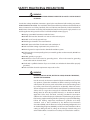
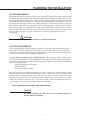
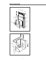
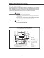
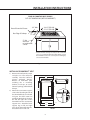
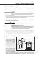
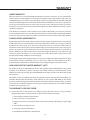
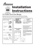
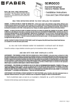
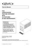
THE PROFESSIONAL DOWNDRAFT
Installation Guide
MODELS:
DD-36SS
DD-30SS
A MESSAGE TO OUR CUSTOMERS
Thank you for selecting this DCS Downdraft Vent System. Because of its unique features, we have developed
this Installation Guide. It contains valuable information on how to properly install your new Downdraft
Vent System for years of safe and enjoyable cooking.
For your convenience, product questions can be answered by a DCS Customer Care Representative by
phone: 1-888-281-5698, email: [email protected]
or by mail:
Fisher & Paykel Appliances, Inc.
Attention: DCS Customer Care
5900 Skylab Road,
Huntington Beach, CA 92647
WARNING
TO REDUCE THE RISK OF A COOKTOP GREASE FIRE:
Never leave surface units unattended at high settings. Boilovers cause
smoking and greasy spillovers that may ignite. Heat oils slowly on low or
medium setting. Always turn the Downdraft “ON” when cooking at high heat
or when cooking flaming foods. Clean ventilating fans frequently. Grease
should not be allowed to accumulate on fan or filter. Use proper pan size.
Always use cookware appropriate for the size of the surface element.
WARNING
TO REDUCE THE RISK OF INJURY TO PERSONS IN THE EVENT OF A COOKTOP
GREASE FIRE, OBSERVE THE FOLLOWING: SMOTHER FLAMES with a closefitting lid, cookie sheet, or metal tray, then turn off the burner. BE CAREFUL TO
PREVENT BURNS. If the flames do not go out immediately EVACUATE AND
CALL THE FIRE DEPARTMENT. NEVER PICK UP A FLAMING PAN - You may be
burned. DO NOT USE WATER, including wet dishcloths or towels - a violent
steam explosion will result. Use an extinguisher ONLY if:
1. You know you have a Class ABC extinguisher, and you already know how to
operate it.
2. The fire is small and contained in the area where it started.
3. The fire department is being called.
4. You can fight the fire with your back to an exit.
PLEASE RETAIN THIS MANUAL FOR FUTURE REFERENCE.
1
TABLE OF CONTENTS
SAFETY PRACTICES & PRECAUTIONS ..............................................................................................................................3
PLANNING THE INSTALLATION...........................................................................................................................................4
Venting Requirements...........................................................................................................................................4
Electrical Requirements ........................................................................................................................................4
SPECIFICATIONS .......................................................................................................................................................................5
INSTALLATION INSTRUCTIONS ....................................................................................................................................6-11
Tools Needed ............................................................................................................................................................6
Plan The Ductwork..................................................................................................................................................6
Calculate the Duct Run Length ..........................................................................................................................6
Plan And Make The Cutout ..................................................................................................................................7
Installing The Downdraft Vent .....................................................................................................................8-11
WIRING DIAGRAM .................................................................................................................................................................12
HOW TO OBTAIN SERVICE ..................................................................................................................................................13
WARRANTY ........................................................................................................................................................................14-15
2
SAFETY PRACTICES & PRECAUTIONS
WARNING:
ALL WALL AND FLOOR OPENINGS WHERE THE Downdraft IS INSTALLED MUST
BE SEALED.
Consult the cooktop installation instructions given by the manufacturer before making any cutouts.
MOBILE HOME INSTALLATION - The installation of this Downdraft must conform to the Manufactured
Home Construction and Safety Standards, Title 24 CFR, Part 3280 (formerly Federal Standard for
Mobile Home Construction and Safety, Title 24, HUD, Part 280). Four wire power supply must be used
and the appliance wiring must be revised. See Electrical Requirements (page 4).
Venting system MUST terminate outside the home.
DO NOT terminate the ductwork in an attic or other enclosed space.
DO NOT use 4" laundry-type wall caps.
Flexible-type ductwork is not recommended.
DO NOT obstruct the flow of combustion and ventilation air.
Failure to follow venting requirements may result in a fire.
Electrical ground is required on this downdraft ventilation system.
If cold water pipe is interrupted by plastic, non-metallic gaskets or other materials, DO NOT use
for grounding.
DO NOT ground to a gas pipe.
DO NOT have a fuse in the neutral or grounding circuit. A fuse in the neutral or grounding
circuit could result in electrical shock.
Check with a qualified electrician if you are in doubt as to whether the downdraft is properly
grounded.
Failure to follow electrical requirements may result in a fire.
WARNING:
TO REDUCE THE RISK OF FIRE, ELECTRICAL SHOCK, OR INJURY TO PERSONS,
OBSERVE THE FOLLOWING:
Use this unit only in the manner intended by the manufacturer. If you have
any questions, contact the manufacturer. Before servicing or cleaning unit,
switch power off at service panel and lock the service disconnecting means
to prevent power from being switched on accidentally. When the service
disconnecting means cannot be locked, securely fasten a prominent warning
device, such as a tag, to the service panel. Installation Work And Electrical
Wiring Must Be Done By Qualified Person(s) In Accordance With All
Applicable Codes And Standards, Including Fire-Rated Construction.
Sufficient air is needed for proper combustion and exhausting of gases from
fuel burning equipment through the flue (chimney) to prevent backdrafting.
Follow the heating equipment manufacturer's guideline and safety
standards such as those published by the National Fire Protection
Association (NFPA), and the American Society for Heating, Refrigeration and
Air Conditioning Engineers (ASHRAE), and the local code authorities. When
cutting or drilling into wall or ceiling, do not damage electrical wiring and
other hidden utilities. Ducted fans must always be vented to the outdoors.
3
PLANNING THE INSTALLATION
VENTING REQUIREMENTS
Determine which venting method is best for your application. Ductwork can extend either through
the wall or the roof. The length of the ductwork and the number of elbows should be kept to a minimum to provide efficient performance. The size of the ductwork should be uniform. Do not install
two elbows together. Use duct tape to seal all joints in the ductwork system. Use caulking to seal exterior wall or floor opening around the cap. Flexible ductwork is not recommended. If it is used, each
foot of flexible ductwork used is equivalent to two feet of straight metal ductwork when calculating
the duct run length. Thus, a flexible elbow equals two standard elbows. Make sure there is proper
clearance within the wall or floor for exhaust duct before making cutouts. Do not cut a joist or stud
unless absolutely necessary. If a joist or stud must be cut, then a supporting frame must be
constructed.
WARNING:
To Reduce The Risk Of Fire, Use Only Metal Ductwork.
ELECTRICAL REQUIREMENTS
A 120 volt, 60 Hz AC-only electrical supply is required on a separate 15 amp circuit, fused on both
sides of the line. A time-delay fuse or circuit breaker is recommended. The fuse must be sized per
local codes in accordance with the electrical rating of this unit as specified on the serial/rating plate
located inside the unit near the field wiring compartment.
THIS UNIT MUST BE CONNECTED WITH COPPER WIRE ONLY. Wire sizes must conform to the requirements of the National Electrical Code, ANSI/NFPA 70 -latest edition, and all local codes and ordinances.
Wire size and connections must conform with the rating of the appliance. Copies of the standard listed
above can be obtained from:
National Fire Protection Association
Battery March Park
Quincy, Massachusetts 02269
This appliance should be connected directly to the fuse disconnect (or circuit breaker) through
flexible, armored or non-metallic sheathed copper cable. Allow some slack in the cable so the
appliance can be moved if servicing is ever necessary. A UL Listed, 1/2" conduit connector must be
provided at each end of the power supply cable (at the appliance and at the junction box). When
making the electrical connection, cut a 1-1/4" hole in the wall. A hole cut through wood must be
sanded until smooth. A hole through metal must have a grommet.
NOTE: SUITABLE FOR USE WITH SOLID STATE SPEED CONTROLS.
CAUTION:
For General Ventilating Use Only. Do Not Use To Exhaust Hazardous or
Explosive Materials and Vapors.
4
SPECIFICATIONS
30"
or
36"
8-1/4"
1-1/2"
27" for 30" model
33" for 36" model
16"
26-1/8"
3-1/4" x 10"
16"
9-3/8"
2-1/8"
Fig. 01 Downdraft Dimensions
4-1/8"
+
1/2 "
min.
23-9/16"
17-3/16"
17-9/16"
3/8"
3-1/4"
3/8"
10"
4-1/8"
+
1/2"
min.
4-1/8"
+
1/2"
min.
FIG.02 Ductwork Cutout Dimensions
5
INSTALLATION INSTRUCTIONS
TOOLS NEEDED FOR INSTALLATION
PARTS SUPPLIED FOR INSTALLATION
Saber Saw or Jig Saw
6 Mounting Brackets
Drill
2 End Caps
1-1/4 Wood Drill Bit
16 Screws
Pliers
1 Backdraft Damper
Phillips Screwdriver
Flat Blade Screwdriver
Wire Stripper or Utility Knife
Metal Snips
Measuring Tape or Ruler
Level
Pencil
Caulking Gun
Duct Tape
PARTS NEEDED FOR INSTALLATION
2 Conduit Connectors
Power Supply Cable
1 Wall or Roof Cap
All Metal Ductwork
PLAN THE DUCTWORK
VENTING DOWN
The DCS 36” and 30” downdraft vent system can be
ducted in four different directions; down, left, right or
back using a 3-1/4" X 10" rectangular vent. Fig. 03
illustrates venting options. Fig. 02 shows the ductwork
cutout dimensions.
VENTING
LEFT
CALCULATE THE DUCT RUN LENGTH
R H
BACK
The ductwork length should not exceed 35 equivalent
feet for 3-1/4" X 10" duct, or 60 equivalent feet for 9"
FIG.03 Ducting
round duct. Calculate the length of the ductwork by
adding the equivalent feet listed in Fig. 04 for each piece
of duct in the complete system. An example is given in Fig. 05. For best results, use no more than
three 90° elbows. Make sure that there is a minimum of 24" of straight duct between elbows if more
than one is used. Do not install two elbows together. Round duct is recommended instead of
rectangular duct especially if elbows are needed. Rectangular duct should transition to round as soon
as possible (6” round minimum).
VENTING
45° Elbow
90° Elbow
90° Flat Elbow
Wall Cap
IG
T
VENTING
9 Feet Straight Duct
2 - 90° Elbows
Wall Cap
Total System
5.0 feet
7.0 feet
12.0 feet
0.0 feet
FIG.04
FIG.05
6
9.0 feet
14.0 feet
0.0 feet
23.0 feet
INSTALLATION INSTRUCTIONS
PLAN AND MAKE THE CUTOUT
It is recommended that the installer draw the cooktop and downdraft cutouts on the countertop
before making any cutouts to avoid mistakes. Fig. 06 shows the cutout dimensions for DCS CT-365
and CT-304 and for all other cooktops see Fig. 06a (page 8). Fig. 07 shows the tolerances between the
cooktop and the downdraft. These tolerances must be observed for proper installation.
WARNING:
When planning the cutout for the downdraft:
Draw both the cooktop and downdraft cutouts on the countertop before
making any cuts.
Check that there is enough room in the cabinet for both. Failure to follow
these warnings could result in damage to the countertop.
WARNING:
These tolerances must be observed!
DCS CT-365 AND CT-304 DROP-IN COOKTOP
CUT-OUT DIMENSIONS (WITH DOWNDRAFT)
K
CAUTION:
36" min. to
combustible
material ,
from cooking
surface
B
G
A
L
E
F
J
H
C
A)
B)
C)
D)
E)
D
I
electrical
and
gas supply
As defined in the “National Fuel Gas Code” (ANSI Z223.1, latest edition).
NOTE: See manufacturer's recommendations for ducting specifications.
NOTE: When installing a 30" Cooktop with a Downdraft (DD-30SS), a minimum of
a 26" cabinetry depth is required.
Fig. 06
7
F)
G)
H)
I)
J)
K)
L)
18” min.
13” max.
5” min. to combustibles∆
19-3/4” depth
34-3/4” width for CT-365
28-5/8” width for CT-304
33-1/2” width for DD36
27-1/2” width for DD30
1/2” min.
2-1/2”
9”
26-1/2”
Min. 36” for CT-365
Min. 30” for CT-304
26” Min.
INSTALLATION INSTRUCTIONS
DROP-IN COOKTOP (MISC. BRAND)
CUT-OUT DIMENSIONS (WITH DOWNDRAFT)
Rear of Downdraft Cutout
Rear Edge of Cooktop
1/2" Min.
33-1/2" (DD-36)
27-1/2" (DD-30)
* 1-3/4"
5" Min.
clearance
to combustible
surface
* Measured from the rear edge of cooktop to rear of downdraft
cutout. It is recommended that the installer draw the cooktop
and downdraft cutouts on the countertop before making any
cutouts to avoid mistakes.
Fig. 06a
INSTALLING DOWNDRAFT VENT
1)
2)
Remove the unit from the carton
and place on a flat surface for
assembly. Cover the surface to
prevent accidental damage.
Remove all downdraft parts
including the 6 mounting
brackets, 2 end caps, 16 screws,
literature package, and backdraft
damper.
Attach the overcounter support
arms to the left and right sides of
the downdraft body as indicated
in Fig. 08. Two short screws are
provided. Attach the end caps to
the left and right sides of the
downdraft over the overcounter
support arms. Attach the lower
support legs to left and right
sides of the downdraft into the
threaded slots on each side.
25 "
1/2" min.
CUTOUT DEPTH
COOKTOP
V
E
N
T
1/4"
36 "
1-7/8"
1/4"
FRONT
COOKTOP
COUNTERTOP
VENT
3/4"
22-1/2"
3/4"
24 "
FIG.07
8
INSTALLATION INSTRUCTIONS
INSTALLING DOWNDRAFT
end cap
(continued)
The lower support legs have
holes for mounting to the
cabinet floor and can be
installed on both sides
depending upon the length
required. Determine if the
holes should be in the front or
on the sides.
UNDER COUNTER
MOUNT BRACKETS
OVER COUNTER
SUPPORT ARMS
3) Carefully insert the unit into
the cutout. Due to the size and
weight, two people are
recommended when lifting
this unit. Make sure that the
downdraft is fully seated in the
cutout and the support arms
rest firmly on the countertop.
4) Adjust the lower support legs
until both rest firmly on the
cabinet floor. Place a level
vertically on the front side of
the blower box to make sure
that the unit is level and not leaning to
the front or rear. Once the unit is properly
aligned, mark a starter hole on the cabinet
floor where the lower support legs will
attach to the cabinet floor.
LOWER SUPPORT LEGS
FIG.08
5) Remove the unit from the cabinet. Drill
starter holes in the cabinet floor for the
leg screws.
6) DCS downdrafts are shipped from the
factory ready to vent in the down
position. If you need to vent back, left or
right, then the blower must be repositioned.
FIG.09
To vent to the left or the right:
Four hex nuts attach the blower box to the
downdraft body. Remove all four nuts and
carefully remove the blower box. To vent left
or right, simply rotate the blower box 90° to
the left or right and re-assemble.
Venting Left, Right or Down
Venting to the Rear
To vent to the rear:
Venting to the rear requires that the blower be
FIG.10
repositioned inside the blower box as
indicated in Fig. 09. The blower is attached to the blower box by 6 screws. Remove the blower from
the blower box. Note the position of the angle mounting rails on each side of the blower. To vent to
the rear, both mounting rails must be repositioned on the blower as illustrated in Fig. 10. Attach the
mounting rails as indicated. Re-attach the blower to the blower box. Re-attach the blower box to
9
INSTALLATION INSTRUCTIONS
INSTALLING DOWNDRAFT (continued)
the downdraft. The square metal frame must be attached to the mouth of the blower. The exhaust
knockout on the rear must be removed. A metal plate and two screws are supplied in the hardware
package to cover the unused exhaust exit.
CAUTION:
Make sure that the wiring cable connecting the blower to the field wiring
compartment remains securely attached under the two cable clamps.
7) Attach the Backdraft Damper.
8) Remove the field wiring compartment cover and determine which direction the wiring will run
from the appliance to the wiring box and remove the wiring knockout.
9) Insert the downdraft unit into the countertop cutout. Make sure that the unit is firmly placed at
the rear of the cutout. Fasten the legs to the cabinet floor using the two longer Phillips head
screws supplied in the hardware package.
WARNING:
When attaching the Under Counter Mounting Brackets:
DO NOT drill into the countertop surface.
Check that the mounting screws are the proper length and will not extend
through the countertop surface when tightened. Failure to follow these
warnings could result in damage to the countertop surface.
10) Attach the downdraft to the countertop using the undercounter mounting brackets (Fig. 08). This
system is designed to adjust to different countertop thicknesses. Using the small Phillips head
machine screws in the hardware package, attach one undercounter mounting bracket to the slot
on the upper right corner of the unit. Attach the other end of the bracket to the underside of the
countertop.
11) Thread the power supply cable through the wiring knockout into the field wiring compartment.
Connect the three white wires
together with a twist-on wire
Up/Down
connector. Connect the two
Button
black wires with a twist-on wire
Blower Control
connector. Attach the Green (or
Switch
Green and Yellow) ground wire
to the eyelet with the green
Knock-out
grounding screw. Replace the
field wiring compartment cover.
Wiring
Grounding
Box
Screw
12) Turn the power supply on. Push
and hold the Up/Down button
momentarily. The downdraft will
rise out of the countertop and
stop in the fully extended
Wiring Box Cover
position. Position the top strip
over the the top of the
downdraft, lining up the fixing
FIG.11
hooks and the hole for the push
button. Snap into place. Turn the blower on. The blower control switch is located on the right
hand side of the plenum as indicated in Fig. 11. If the blower does not work, refer to section
entitled "If The Blower Does Not Operate" located on page 11"
10
INSTALLATION INSTRUCTIONS
INSTALLING DOWNDRAFT (continued)
13) Connect the ductwork to the Backdraft damper. Seal all joints with duct tape and vent to the
outside of the home.
14) Install the cooktop according to the cooktop manufacturer's instructions. Check to make sure
that the rear edge of the cooktop overlaps the front edge of the downdraft by 3/8".
IF THE BLOWER DOES NOT OPERATE:
1) Check that the circuit breaker is not tripped or the house fuse blown.
2) Check that the grease filters are properly installed. (See the section on Safety Microswitches
page 4 of Use and Care Guide).
3) Disconnect the power supply and check that the wiring connections have been made properly.
11
WIRING DIAGRAM
SWITCH
FAN N.O.
BLU
GEAR
MOTOR
BLK
ISWITCH
DOWN N.C.
SWITCH
FILTER N.O.
BLK
BLK
PUSH
BUTTON
N.O.
WHT
M
BLU
BLU
WHT
BLK
BLK
11 UF
WHT
BLK
BLOWER
MOTOR
8/50K-A120
BLK
GRN
WHT
LINE IN
120 VAC
60 Hz
WIRING
BOX
WHT
BLK
12
WHT
BLK
SPEED
CONTROL
BLK
SWITCH
UP N.C.
BLK
SERVICE
HOW TO OBTAIN SERVICE:
Before you call for service:
1) Is the circuit breaker tripped or the fuse blown?
2) Is there a power outage in the area?
3) Are the grease filters properly installed?
4) Will the unit go up/down and the motor control is ON?
For warranty service, contact DCS Customer Care at (888) 281-5698. Before you call, please have the
following information ready:
Model Number
Serial Number
Date of installation
A brief description of the problem
Your satisfaction is of the utmost importance to us. If a problem cannot be resolved to your satisfaction,
please write at:
Write:
Fisher & Paykel Appliances, Inc.
Attention: DCS Customer Care
5900 Skylab Road
Huntington Beach, CA 92647
13
WARRANTY
LIMITED WARRANTY
When you purchase a new DCS Ventilation Product for personal or consumer use you automatically
receive a One year Limited Warranty covering parts and labor for the entire product, and a Five year
Limited Warranty on the switches and motor (parts only) for servicing within the 48 mainland United
States, Hawaii,Washington D.C and Canada. In Alaska the Limited Warranty is the same except that you
must pay to ship the Product to the service shop or for the service technician’s travel to your home.
Products for use in Canada must be purchased through the Canadian distribution channel to ensure
regulatory compliance.
If the Product is installed in a motor vehicle, boat or similar mobile facility, you receive the same One
year Limited Warranty, but you must bring the vehicle, boat or mobile facility containing the Product
to the service shop at your expense or pay the service technician’s travel to the location of the Product.
FISHER & PAYKEL UNDERTAKES TO:
Repair without cost to the owner either for material or labor any part of the Product, the serial number
of which appears on the Product, which is found to be defective. In Alaska, you must pay to ship the
Product to the service shop or for the service technician’s travel to your home. If the Product is
installed in a motor vehicle, boat or similar mobile facility, you must bring it to the service shop at your
expense or pay for the service technician’s travel to the location of the Product. If we are unable to
repair a defective part of the Product after a reasonable number of attempts, at our option we may
replace the part or the Product, or we may provide you a full refund of the purchase price of the
Product (not including installation or other charges).
This warranty extends to the original purchaser and any succeeding owner of the Product for products
purchased for ordinary single-family home use. All service under this Limited Warranty shall be
provided by Fisher & Paykel or its Authorized DCS Service Agent during normal business hours.
HOW LONG DOES THIS LIMITED WARRANTY LAST?
Our liability under this Limited Warranty for the entire product expires ONE YEAR from the date of
purchase of the Product by the first consumer. Our liability under this Limited Warranty for the
switches and motor (parts only) expires FIVE YEARS from the date of purchase of the Product by the
first consumer.
Our liability under any implied warranties, including the implied warranty of merchantability (an
unwritten warranty that the Product is fit for ordinary use) also expires ONE YEAR (or such longer
period as required by applicable law) from the date of purchase of the Product by the first consumer.
Some states do not allow limitations on how long an implied warranty lasts, so this limit on implied
warranties may not apply to you.
THIS WARRANTY DOES NOT COVER:
A. Service calls that are not related to any defect in the Product. The cost of a service call will be
charged if the problem is not found to be a defect of the Product. For example:
1. Correct faulty installation of the Product.
2. Instruct you how to use the Product.
3. Replace house fuses, reset circuit breakers, correct house wiring or plumbing, or replace light
bulbs.
4. Correct fault(s) caused by the user.
5. Change the set-up of the Product.
6. Unauthorized modifications of the Product.
14
WARRANTY
7. Noise or vibration that is considered normal, for example, drain/fan sounds, regeneration
noises or user warning beeps.
8. Correcting damage caused by pests, for example, rats, cockroaches etc.
B. Defects caused by factors other than:
1. Normal domestic use or
2. Use in accordance with the Product’s User Guide.
C. Defects to the Product caused by accident, neglect, misuse, fire, flood or Act of God.
D. The cost of repairs carried out by non-authorized repairers or the cost of correcting such
unauthorized repairs.
E. Travel Fees and associated charges incurred when the product is installed in a location with limited
or restricted access. (i.e. airplane flights, ferry charges, isolated geographic areas).
F. Normal recommended maintenance as set forth in the Product’s User Guide.
If you have an installation problem contact your dealer or installer. You are responsible for providing
adequate electrical, exhausting and other connection facilities. We are not responsible for
consequential or incidental damages (the cost of repairing or replacing other property damaged if the
Product is defective or any of your expenses caused if the Product is defective). Some states do not
allow the exclusion or limitation of incidental or consequential damages, so the above limitation or
exclusion may not apply to you.
HOW TO GET SERVICE
Please read your User Guide. If you then have any questions about operating the Product, need the
name of your local DCS Authorized Service Agent, or believe the Product is defective and wish service
under this Limited Warranty, please contact your dealer or call us at:
TOLL FREE 1-888-281 5698 or contact us through our web site: www.dcsappliances.com.
You may be required to provide reasonable proof of the date of purchase of the Product before the
Product will be serviced under this Limited Warranty.
COMMERCIAL USE
This warranty applies to appliances used in residential applications; it does not cover their use in
commercial situations.
NO OTHER WARRANTIES
This Limited Warranty is the complete and exclusive agreement between you and Fisher & Paykel
regarding any defect in the Product. None of our employees (or our Authorized Service Agents) are
authorised to make any addition or modification to this Limited Warranty.
Warrantor: Fisher & Paykel Appliances, Inc.
If you need further help concerning this Limited Warranty, please call us at the above number, or write
to:
Fisher & Paykel Appliances, Inc.
5900 Skylab Road, Huntington Beach, CA 92647
This Limited Warranty gives you specific legal rights, and you may also have other rights which vary
from state to state.
15
Fisher & Paykel Appliances, Inc.
5900 Skylab Road, Huntington Beach, CA 92647
Customer Care: 888.281.5698
Fax: 714.372.7003
www.dcsappliances.com
As product improvement is an ongoing process at DCS,
we reserve the right to change specifications or design
without notice.
DCS améliore constamment ses produits et se réserve le
droit de modifier les spécifications ou la conception de
ses produits sans aucun préavis.
Part No. 17493 Rev. C
Litho in USA 02/2005