1
INSTALLATION INSTRUCTIONS
PLAN AND MAKE THE CUTOUT
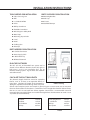
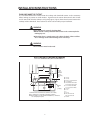
It is recommended that the installer draw the cooktop and downdraft cutouts on the countertop
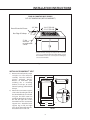
before making any cutouts to avoid mistakes. Fig. 06 shows the cutout dimensions for DCS CT-365
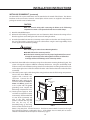
and CT-304 and for all other cooktops see Fig. 06a (page 8). Fig. 07 shows the tolerances between the
cooktop and the downdraft. These tolerances must be observed for proper installation.
WARNING:
When planning the cutout for the downdraft:
Draw both the cooktop and downdraft cutouts on the countertop before
making any cuts.
Check that there is enough room in the cabinet for both. Failure to follow
these warnings could result in damage to the countertop.
WARNING:
These tolerances must be observed!
DCS CT-365 AND CT-304 DROP-IN COOKTOP
CUT-OUT DIMENSIONS (WITH DOWNDRAFT)
K
CAUTION:
36" min. to
combustible
material ,
from cooking
surface
B
G
A
L
E
F
J
H
C
A)
B)
C)
D)
E)
D
I
electrical
and
gas supply
As defined in the “National Fuel Gas Code” (ANSI Z223.1, latest edition).
NOTE: See manufacturer's recommendations for ducting specifications.
NOTE: When installing a 30" Cooktop with a Downdraft (DD-30SS), a minimum of
a 26" cabinetry depth is required.
Fig. 06
7
F)
G)
H)
I)
J)
K)
L)
18” min.
13” max.
5” min. to combustibles∆
19-3/4” depth
34-3/4” width for CT-365
28-5/8” width for CT-304
33-1/2” width for DD36
27-1/2” width for DD30
1/2” min.
2-1/2”
9”
26-1/2”
Min. 36” for CT-365
Min. 30” for CT-304
26” Min.