1
INSTALLATION INSTRUCTIONS
DROP-IN COOKTOP (MISC. BRAND)
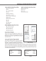
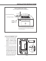
CUT-OUT DIMENSIONS (WITH DOWNDRAFT)
Rear of Downdraft Cutout
Rear Edge of Cooktop
1/2" Min.
33-1/2" (DD-36)
27-1/2" (DD-30)
* 1-3/4"
5" Min.
clearance
to combustible
surface
* Measured from the rear edge of cooktop to rear of downdraft
cutout. It is recommended that the installer draw the cooktop
and downdraft cutouts on the countertop before making any
cutouts to avoid mistakes.
Fig. 06a
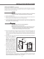
INSTALLING DOWNDRAFT VENT
1)
2)
Remove the unit from the carton
and place on a flat surface for
assembly. Cover the surface to
prevent accidental damage.
Remove all downdraft parts
including the 6 mounting
brackets, 2 end caps, 16 screws,
literature package, and backdraft
damper.
Attach the overcounter support
arms to the left and right sides of
the downdraft body as indicated
in Fig. 08. Two short screws are
provided. Attach the end caps to
the left and right sides of the
downdraft over the overcounter
support arms. Attach the lower
support legs to left and right
sides of the downdraft into the
threaded slots on each side.
25 "
1/2" min.
CUTOUT DEPTH
COOKTOP
V
E
N
T
1/4"
36 "
1-7/8"
1/4"
FRONT
COOKTOP
COUNTERTOP
VENT
3/4"
22-1/2"
3/4"
24 "
FIG.07
8