1
Electric Drives
and Controls
Hydraulics
Linear Motion and
Assembly Technologies
Pneumatics
Rexroth IndraControl VCH 08.1
Project Planning Manual
Service
R911320190
Edition 01
Bosch Rexroth AG | Electric Drives
and Controls
Title
Type of Documentation
Document Typecode
Internal File Reference
Purpose of Documentation
Record of Revision
Copyright
Rexroth IndraControl VCH 08.1 | Project Planning Manual
Rexroth IndraControl VCH 08.1
Project Planning Manual
DOK-SUPPL*-VCH*08.1***-PR01-EN-P
RS-9dbe22ee76daf77d0a6846a0018e2a10-1-en-US-6
This documentation
VCH 08.1.
describes
the
hand-held
terminals
IndraControl
Edition
Release Date
Notes
120-2100-B391-01/EN
02.2008
First edition
© Bosch Rexroth AG, 2007
Unless otherwise expressly permitted, the publication or duplication of this
document and the utilisation or communication of its contents is not permitted.
Non compliance will result in legal action for damages. All rights for the granting
of a patent or the registration of a design reserved (DIN 34-1).
Liability
Published by
The data stated merely serves the description of the product and is not to be
understood as being contractually committed property in the legal sense. All
rights of changes to the contents of the documentation and supply options of
the products are reserved.
Bosch Rexroth AG
Bgm.-Dr.-Nebel-Str. 2 ■ 97816 Lohr am Main, Germany
Telephone +49 (0)93 52/ 40-0 ■ Fax +49 (0)93 52/ 40-48 85
http://www.boschrexroth.com/
Dept. BRC/EAY2 (BaWe/MePe)
Dept. BRC/EAP2 (EH/MePe)
Note
This document has been printed on chlorine-free paper.
Project Planning Manual | Rexroth IndraControl VCH 08.1
Electric Drives | Bosch Rexroth AG
and Controls
I/IV
Table of Contents
Table of Contents
Page
1
1.1
1.2
1.3
1.4
1.5
1.6
1.7
2
2.1
2.1.1
2.1.2
2.2
3
3.1
3.1.1
3.1.2
3.1.3
3.1.4
3.2
3.2.1
3.2.2
3.2.3
3.2.4
3.2.5
3.2.6
3.2.7
3.2.8
4
4.1
4.2
4.3
4.4
4.5
4.6
4.7
4.8
4.9
4.10
4.11
System Presentation...................................................................................................... 1
Overview................................................................................................................................................. 1
Casing..................................................................................................................................................... 1
Keypad.................................................................................................................................................... 1
Front View of the IndraControl VAC 08.1............................................................................................... 2
Front View of the IndraControl VAC 30.2............................................................................................... 2
Operating System................................................................................................................................... 3
Start up .................................................................................................................................................. 3
Important Instructions for Use ....................................................................................... 5
Appropriate Use ..................................................................................................................................... 5
Introduction.......................................................................................................................................... 5
Areas of Use and Application.............................................................................................................. 5
Inappropriate Use................................................................................................................................... 6
Safety Instructions for Electric Drives and Controls....................................................... 7
Safety Instructions - General Information............................................................................................... 7
Using the Safety Instructions and Passing them on to Others............................................................ 7
How to Employ the Safety Instructions................................................................................................ 7
Explanation of Warning Symbols and Degrees of Hazard Seriousness.............................................. 8
Hazards by Improper Use.................................................................................................................... 9
Instructions with Regard to Specific Dangers....................................................................................... 10
Protection Against Contact with Electrical Parts and Housings......................................................... 10
Protection Against Electric Shock by Protective Extra-Low Voltage................................................. 11
Protection Against Dangerous Movements....................................................................................... 11
Protection Against Magnetic and Electromagnetic Fields During Operation and Mounting.............. 14
Protection Against Contact with Hot Parts......................................................................................... 14
Protection During Handling and Mounting......................................................................................... 14
Battery Safety.................................................................................................................................... 15
Protection Against Pressurized Systems........................................................................................... 15
Technical Data............................................................................................................. 17
IndraControl VCH 08.1......................................................................................................................... 17
Keypad, Casing and Display................................................................................................................. 17
STOP Push Button............................................................................................................................... 17
Enabling Device ................................................................................................................................... 18
Connection Module VAC 30.2.............................................................................................................. 18
Ambient Conditions............................................................................................................................... 19
Accessories.......................................................................................................................................... 19
Identification.......................................................................................................................................... 19
Weight................................................................................................................................................... 19
Applied Standards................................................................................................................................ 20
Compatibility Test................................................................................................................................. 21
II/IV
Bosch Rexroth AG | Electric Drives
and Controls
Rexroth IndraControl VCH 08.1 | Project Planning Manual
Table of Contents
Page
5
5.1
5.2
5.3
6
6.1
6.1.1
6.1.2
6.1.3
6.1.4
6.1.5
6.2
6.2.1
6.2.2
6.3
6.4
6.5
6.5.1
6.5.2
6.5.3
6.5.4
6.5.5
6.5.6
7
7.1
7.1.1
7.1.2
7.2
7.3
7.3.1
7.3.2
7.3.3
Dimensions.................................................................................................................. 23
Casing Dimensions of the IndraControl VCH 08.1............................................................................... 23
Casing and Mounting Dimensions of the IndraControl VAC 30.2......................................................... 24
Dimensions of the Wall Bracket VAS 01.1 ........................................................................................... 25
Display and Operating Components............................................................................ 27
Operating Elements ............................................................................................................................. 27
Overview............................................................................................................................................ 27
Casing of the IndraControl VAC 08.1................................................................................................ 27
Overview......................................................................................................................................... 27
Ergonomics..................................................................................................................................... 28
Keypad.............................................................................................................................................. 29
Position of the Keys on the IndraControl VCH 08.1....................................................................... 29
Safety Operating Elements ............................................................................................................... 29
Safety Concept............................................................................................................................... 29
Enabling Function........................................................................................................................... 30
Predictable Misuse of the Enabling Switch..................................................................................... 31
STOP Push Button......................................................................................................................... 32
Functionality of the STOP Circuit Jumper...................................................................................... 32
Optional Operating Elements............................................................................................................ 33
Additional Components.................................................................................................................. 33
Override Potentiometer.................................................................................................................. 34
Elektronic Hand Wheel................................................................................................................... 34
Display.................................................................................................................................................. 34
Overview............................................................................................................................................ 34
Contrast Setting................................................................................................................................. 34
Character Attributes.............................................................................................................................. 35
Character Sets...................................................................................................................................... 35
Keypad.................................................................................................................................................. 35
Overview............................................................................................................................................ 35
Editing Keys....................................................................................................................................... 35
Function Keys.................................................................................................................................... 36
Shift Key............................................................................................................................................ 36
Navigation Keys................................................................................................................................. 37
Special Keys...................................................................................................................................... 37
Pin Assignments of the IndraControl VCH 08.1........................................................... 39
Laying the Cables in the Cable Chamber............................................................................................. 39
Image of the Cable Chamber............................................................................................................ 39
Laying the Cables.............................................................................................................................. 39
STOP Switch........................................................................................................................................ 41
Connection of the IndraControl VCH 08.1 via IndraControl VAC 30.2................................................. 42
Overview............................................................................................................................................ 42
Pin Assignment of the IndraControl VAC 30.2.................................................................................. 43
X1: 24 VDC Power Supply ............................................................................................................... 44
Project Planning Manual | Rexroth IndraControl VCH 08.1
Electric Drives | Bosch Rexroth AG
and Controls
III/IV
Table of Contents
Page
7.3.4
7.3.5
7.3.6
7.4
8
8.1
8.2
8.3
9
9.1
9.2
9.2.1
9.2.2
9.2.3
9.2.4
9.2.5
9.2.6
9.2.7
9.3
9.3.1
9.3.2
9.4
9.5
9.5.1
9.5.2
9.5.3
9.5.4
9.5.5
10
10.1
10.1.1
X2.1: STOP Push Button .................................................................................................................. 47
Pin Assignment............................................................................................................................... 47
X2.2: Enabling Device....................................................................................................................... 47
Pin Assignment............................................................................................................................... 47
Examples for the Connection of the Enabling Switch..................................................................... 47
X3: Ethernet Interface ....................................................................................................................... 51
Personality Function............................................................................................................................. 51
Maintenance and Installation....................................................................................... 55
General Information.............................................................................................................................. 55
LCD Display.......................................................................................................................................... 55
Maintenance of the IndraControl VCH 08.1.......................................................................................... 55
Software....................................................................................................................... 57
Overview............................................................................................................................................... 57
Starting the IndraControl VCH 08.1...................................................................................................... 57
General Information........................................................................................................................... 57
Start-up Application .......................................................................................................................... 59
Customer Application........................................................................................................................ 60
Service Dialog................................................................................................................................... 60
Config Tool........................................................................................................................................ 61
Rexroth Settings................................................................................................................................ 61
Basic Settings.................................................................................................................................... 63
Evaluating the Commands of the Operating Elements......................................................................... 63
General Information........................................................................................................................... 63
Evaluation of the Operating Status in the Control............................................................................. 63
Remote Software ActiveSync............................................................................................................... 65
Operating Notes for the VCH 08.1........................................................................................................ 66
General Information........................................................................................................................... 66
Setting of Date and Time................................................................................................................... 66
Configuration Tool (Config Tool)....................................................................................................... 66
General Information........................................................................................................................ 66
Potentiometer Calibration............................................................................................................... 66
Display Settings ............................................................................................................................. 67
Setting the Zero Point of the Handwheel........................................................................................ 67
Switch-on Actions for Restart (Start-up)......................................................................................... 68
System Update............................................................................................................................... 68
Information on Version................................................................................................................... 69
Checking the Keyboard.................................................................................................................. 69
Saving Data....................................................................................................................................... 70
Transmission of Data......................................................................................................................... 70
Disposal and Environmental Protection....................................................................... 71
Disposal................................................................................................................................................ 71
Products............................................................................................................................................ 71
IV/IV
Bosch Rexroth AG | Electric Drives
and Controls
Rexroth IndraControl VCH 08.1 | Project Planning Manual
Table of Contents
Page
10.1.2
10.2
10.2.1
10.2.2
10.2.3
11
11.1
11.1.1
11.1.2
11.1.3
11.2
11.2.1
11.3
11.3.1
12
12.1
12.2
12.3
12.4
Packaging Materials.......................................................................................................................... 71
Environmental Protection...................................................................................................................... 71
No Release of Hazardous Substances.............................................................................................. 71
Materials Contained in the Products.................................................................................................. 71
Electronic Devices.......................................................................................................................... 71
Motors............................................................................................................................................. 71
Recycling........................................................................................................................................... 72
Ordering Information.................................................................................................... 73
Type Code............................................................................................................................................ 73
General Information........................................................................................................................... 73
IndraControl VCH 08.1...................................................................................................................... 74
IndraControl VAC 30.2...................................................................................................................... 75
Accessories.......................................................................................................................................... 75
Wall Bracket...................................................................................................................................... 75
Spare Parts........................................................................................................................................... 75
Connection Cable.............................................................................................................................. 75
Service and Support.................................................................................................... 77
Helpdesk............................................................................................................................................... 77
Service Hotline...................................................................................................................................... 77
Internet.................................................................................................................................................. 77
Helpful Information................................................................................................................................ 77
Index............................................................................................................................ 79
Project Planning Manual | Rexroth IndraControl VCH 08.1
Electric Drives | Bosch Rexroth AG
and Controls
1/80
System Presentation
1
System Presentation
1.1
Overview
The hand-held terminal IndraControl VCH 08.1 is a portable operation and vis‐
ualization device of rugged design with Windows CE compatible electronics.
Through its use of a powerful processor and configuration with ethernet, the
hand-held terminal IndraControl VCH 08.1 is ideally equipped for a variety of
applications (see chapter 2.1 "Appropriate Use " on page 5).
Instead of rotating mass storage devices such as floppy discs and hard drives,
which are not suitable for rough operating conditions, the IndraControl
VCH 08.1 contains FLASH- and RAM databases.
The IndraControl VCH 08.1 offers a Windows CE platform which can be equip‐
ped with applications using the VI Composer.
Through its optional operation and control elements, the IndraControl
VCH 08.1can be easily adapted to individual cases of operation.
The IndraControl VCH 08.1 is, for example, suited to the following areas of
application:
●
Operation and visualization of IndraLogic, IndraMotion MLC and Indra‐
Motion MTX.
●
Installation of machines and systems.
●
Operation and diagnosis of extended handling systems.
●
Visualization of simple operating fields on assembly lines.
For the normal operating modes, the "automatic" mode of operation is available,
for instance.
In the special modes of operation, such as semi-automatic and manual, the
options of installation, teaching, test runs and other functions are available.
An acceptance unit and also a STOP switch are installed in the IndraControl
VCH 08.1 as safety functions.
Manual operation terminals that are intended for temporary connection do not
need to have a red-yellow emergency stop switch. A manual operation terminal
with a gray STOP switch is available for this use case.
All of the safety functions are designed as dual circuits to ensure compliance
with safety category 4 according to EN 954-1.
The selection of the manual operating terminal which is suited to the machine
and the project planning of the possible additional options must be completed
under the responsibility of the machine manufacturer and on the basis of a
statutory evaluation of the dangers and risks.
1.2
Casing
The vibration and shock-proof casing consists of fire resistant material (UL 94V0). It is impact resistant and resistant to water, cleaning agents (alcohols and
tensides), oils, cutting oils (drilling oils), grease and lubricants. The double wal‐
led and extremely robust casing has been tested with a free fall onto an
industrial floor from a height of 1.5 m.
1.3
Keypad
The keypad consists of a chemical resistant polyester film which is equipped
with embossed keys.
2/80
Bosch Rexroth AG | Electric Drives
and Controls
Rexroth IndraControl VCH 08.1 | Project Planning Manual
System Presentation
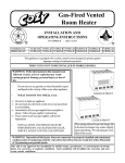
1.4
Front View of the IndraControl VAC 08.1
①
②
③
④
⑤
Fig.1-1:
1.5
Installation point for the override potentiometer
Installation point for electronic hand wheel
Emergency STOP key, dual circuit, or STOP push button
Keypad
Display
Front view of the IndraControl VAC 08.1
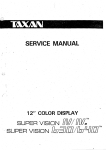
Front View of the IndraControl VAC 30.2
The hand-held terminal IndraControl VCH 08.1 is connected with the controller
via the IndraControl VAC 30.2 connection module. All of the connections for
wiring the connection module with the controller are located on the rear side of
the IndraControl VAC 30.2. At the front side, a 17pin female connector with a
screw top enables the easy connection of a IndraControl VCH 08.1.
Project Planning Manual | Rexroth IndraControl VCH 08.1
Electric Drives | Bosch Rexroth AG
and Controls
3/80
System Presentation
Fig.1-2:
1.6
Front view of the VAC 30.2
Operating System
For license related reasons IndraControl VCH 08.1 -type devices are only sup‐
plied with previously installed operating systems. For further information about
the operating system, please refer to chapter 9 "Software" on page 57.
1.7
Start up
Mount the IndraControl VAC 30.2 connection module according to the instruc‐
tions in chapter 5 "Dimensions" on page 23. Next, connect the connection
module to the power supply, the STOP circuit, the enabling circuit and to the
network.
Before starting up the IndraControl VCH 08.1 the operator must ensure that the
system, and especially the safety equipment, is in correct working order.
Before starting up the IndraControl VCH 08.1 it must be ensured
that the STOP push button is not depressed. The connection of a
IndraControl VCH 08.1 with a depressed STOP push button would
shut down the system.
To connect the IndraControl VCH 08.1, without applying any force, fit the angled
connector onto the flange of the VAC 30.2 connection module at an angle of
45° (to horizontal); refer tofig. 1-3 "Plug orientation at the
IndraControl VAC 30.2" on page 4. The correct position is only achieved if
the connector snaps in to place properly. Now turn the knurled nut on the flange,
applying a little pressure.
4/80
Bosch Rexroth AG | Electric Drives
and Controls
Rexroth IndraControl VCH 08.1 | Project Planning Manual
System Presentation
Fig.1-3:
Plug orientation at the IndraControl VAC 30.2
While the connector is being screwed on, a relay activates the
STOP push button. This ensures that the IndraControl VCH 08.1 is
supplied with power. To ensure the optimal connection of the con‐
tacts and to achieve the specified degree of protection, screw the
knurled nut until the rubber seal is completely covered and the end
position is reached.
During the starting up of the IndraControl VCH 08.1 and during routine opera‐
tion, regularly check all three positions of the enabling device on both sides for
correct functioning.
The device may only be started up and connected by appropriately qualified
staff.
The device and systems manufacturer provides further details about the startup in their documentation.
Project Planning Manual | Rexroth IndraControl VCH 08.1
Electric Drives | Bosch Rexroth AG
and Controls
5/80
Important Instructions for Use
2
Important Instructions for Use
2.1
Appropriate Use
2.1.1
Introduction
Rexroth products are developed and manufactured in accordance with the lat‐
est technologies. They are tested prior to delivery for their safe operation and
reliability.
The products may only be used appropriately. If the use is inappropriate, sit‐
uations may arise which can cause both physical damage as well as damage
to property.
As a manufacturer, Rexroth is unable to undertake any guarantee,
liability or payment of compensation pertaining to damages caused
by the inappropriate use of its products. The user is solely respon‐
sible for all risks resulting from the products which are not used as
intended.
Before you use Bosch Rexroth products, the following requirements must be
fulfilled in order to guarantee the appropriate use of the products:
2.1.2
●
Anyone handling a Rexroth product in any way must read and understand
the corresponding safety instructions as well as the instructions on ap‐
propriate use.
●
Hardware products must remain in their original state, in other words, no
modifications regarding their design may occur. Software products may
not be decompiled and their source codes may not be modified.
●
Damaged or faulty products may not to be installed or put into operation.
●
It must to be ensured that the products are installed according to the
specifications whcih are set out in the documentation.
Areas of Use and Application
The hand-held terminalIndraControl VCH 08.1 is a PC-based operation and
visualization device that can also complete control functions depending on the
application and configuration.
The hand-held terminalIndraControl VCH 08.1 may only be used
with the accessories and add-ons which are specified in this docu‐
mentation. Components which are not explicitly named may neither
be added nor connected. The same applies to cables and wires.
Operation my only be carried out in the specified configurations and
combinations of the components and with the software and firm‐
ware stated in the corresponding functional descriptions.
The hand-held terminalIndraControl VCH 08.1 has been developed for use in
control tasks.
Typical areas of application for the hand-held terminalIndraControl VCH 08.1:
●
Handling systems and assembly systems,
●
packaging and food processing machines,
●
printing and paper processing machines, and
●
machine tools.
6/80
Bosch Rexroth AG | Electric Drives
and Controls
Rexroth IndraControl VCH 08.1 | Project Planning Manual
Important Instructions for Use
IndraControl VCH 08.1 - type devices may only be operated under the assembly
conditions and installation conditions, in the specified purpose and under the
specified ambient conditions (temperature, protection type, humidity, EMC etc.)
which are stated in this documentation.
2.2
Inappropriate Use
The use of the hand-held terminalIndraControl VCH 08.1 outside the specified
areas of application or under operating conditions which deviate from the op‐
erating conditions and technical data specified in the documentation is consid‐
ered to be "inappropriate".
The hand-held terminalIndraControl VCH 08.1 may not be used if
●
it is exposed to operating conditions that do not fulfill the sepcified ambient
conditions. For example, operation under water, under extreme fluctua‐
tions of temperature and extremely high temperatures
●
which are not exlicitly approved for the application of Bosch Rexroth prod‐
ucts are not permitted. Please read the information which is stated in the
general safety instructions.
Project Planning Manual | Rexroth IndraControl VCH 08.1
Electric Drives | Bosch Rexroth AG
and Controls
7/80
Safety Instructions for Electric Drives and Controls
3
Safety Instructions for Electric Drives and Controls
3.1
Safety Instructions - General Information
3.1.1
Using the Safety Instructions and Passing them on to Others
Do not attempt to install or commission this device without first reading all doc‐
umentation provided with the product. Read and understand these safety
instructions and all user documentation prior to working with the device. If you
do not have the user documentation for the device, contact your responsible
Bosch Rexroth sales representative. Ask for these documents to be sent im‐
mediately to the person or persons responsible for the safe operation of the
device.
If the device is resold, rented and/or passed on to others in any other form,
these safety instructions must be delivered with the device in the official lan‐
guage of the user's country.
WARNING
3.1.2
Improper use of these devices, failure to follow the safety instructions in
this document or tampering with the product, including disabling of safe‐
ty devices, may result in material damage, bodily harm, electric shock
or even death!
Observe the safety instructions!
How to Employ the Safety Instructions
Read these instructions before initial commissioning of the equipment in order
to eliminate the risk of bodily harm and/or material damage. Follow these safety
instructions at all times.
●
Bosch Rexroth AG is not liable for damages resulting from failure to ob‐
serve the warnings provided in this documentation.
●
Read the operating, maintenance and safety instructions in your language
before commissioning the machine. If you find that you cannot completely
understand the documentation for your product, please ask your supplier
to clarify.
●
Proper and correct transport, storage, assembly and installation, as well
as care in operation and maintenance, are prerequisites for optimal and
safe operation of this device.
●
Only assign trained and qualified persons to work with electrical installa‐
tions:
●
–
Only persons who are trained and qualified for the use and operation
of the device may work on this device or within its proximity. The
persons are qualified if they have sufficient knowledge of the assem‐
bly, installation and operation of the product, as well as an under‐
standing of all warnings and precautionary measures noted in these
instructions.
–
Furthermore, they must be trained, instructed and qualified to switch
electrical circuits and devices on and off in accordance with technical
safety regulations, to ground them and to mark them according to the
requirements of safe work practices. They must have adequate safe‐
ty equipment and be trained in first aid.
Only use spare parts and accessories approved by the manufacturer.
8/80
Bosch Rexroth AG | Electric Drives
and Controls
Rexroth IndraControl VCH 08.1 | Project Planning Manual
Safety Instructions for Electric Drives and Controls
●
Follow all safety regulations and requirements for the specific application
as practiced in the country of use.
●
The devices have been designed for installation in industrial machinery.
●
The ambient conditions given in the product documentation must be ob‐
served.
●
Only use safety-relevant applications that are clearly and explicitly ap‐
proved in the Project Planning Manual. If this is not the case, they are
excluded. Safety-relevant are all such applications which can cause dan‐
ger to persons and material damage.
●
The information given in the documentation of the product with regard to
the use of the delivered components contains only examples of applica‐
tions and suggestions.
The machine and installation manufacturer must
–
make sure that the delivered components are suited for his individual
application and check the information given in this documentation
with regard to the use of the components,
–
make sure that his application complies with the applicable safety
regulations and standards and carry out the required measures,
modifications and complements.
●
Commissioning of the delivered components is only permitted once it is
sure that the machine or installation in which they are installed complies
with the national regulations, safety specifications and standards of the
application.
●
Operation is only permitted if the national EMC regulations for the appli‐
cation are met.
●
The instructions for installation in accordance with EMC requirements can
be found in the section on EMC in the respective documentation (Project
Planning Manuals of components and system).
The machine or installation manufacturer is responsible for compliance
with the limiting values as prescribed in the national regulations.
●
Technical data, connection and installation conditions are specified in the
product documentation and must be followed at all times.
National regulations which the user must take into account
●
European countries: according to European EN standards
●
United States of America (USA):
–
National Electrical Code (NEC)
–
National Electrical Manufacturers Association (NEMA), as well as
local engineering regulations
–
regulations of the National Fire Protection Association (NFPA)
●
Canada: Canadian Standards Association (CSA)
●
Other countries:
–
International Organization for Standardization (ISO)
–
International Electrotechnical Commission (IEC)
3.1.3
Explanation of Warning Symbols and Degrees of Hazard Seriousness
The safety instructions describe the following degrees of hazard seriousness.
The degree of hazard seriousness informs about the consequences resulting
from non-compliance with the safety instructions:
Project Planning Manual | Rexroth IndraControl VCH 08.1
Electric Drives | Bosch Rexroth AG
and Controls
9/80
Safety Instructions for Electric Drives and Controls
Warning symbol
Fig.3-1:
3.1.4
Signal word
Degree of hazard serious‐
ness acc. to ANSI Z
535.4-2002
Danger
Death or severe bodily harm
will occur.
Warning
Death or severe bodily harm
may occur.
Caution
Minor or moderate bodily
harm or material damage
may occur.
Hazard classification (according to ANSI Z 535)
Hazards by Improper Use
High electric voltage and high working current! Risk of death or severe
bodily injury by electric shock!
DANGER
Observe the safety instructions!
Dangerous movements! Danger to life, severe bodily harm or material
damage by unintentional motor movements!
DANGER
Observe the safety instructions!
High electric voltage because of incorrect connection! Risk of death or
bodily injury by electric shock!
WARNING
Observe the safety instructions!
Health hazard for persons with heart pacemakers, metal implants and
hearing aids in proximity to electrical equipment!
WARNING
Observe the safety instructions!
Hot surfaces on device housing! Danger of injury! Danger of burns!
Observe the safety instructions!
CAUTION
Risk of injury by improper handling! Risk of bodily injury by bruising,
shearing, cutting, hitting or improper handling of pressurized lines!
CAUTION
Observe the safety instructions!
10/80
Bosch Rexroth AG | Electric Drives
and Controls
Rexroth IndraControl VCH 08.1 | Project Planning Manual
Safety Instructions for Electric Drives and Controls
Risk of injury by improper handling of batteries!
Observe the safety instructions!
CAUTION
3.2
Instructions with Regard to Specific Dangers
3.2.1
Protection Against Contact with Electrical Parts and Housings
This section concerns devices and drive components with voltages
of more than 50 Volt.
Contact with parts conducting voltages above 50 Volts can cause personal
danger and electric shock. When operating electrical equipment, it is unavoid‐
able that some parts of the devices conduct dangerous voltage.
High electrical voltage! Danger to life, electric shock and severe bodily
injury!
DANGER
●
Only those trained and qualified to work with or on electrical equipment
are permitted to operate, maintain and repair this equipment.
●
Follow general construction and safety regulations when working on pow‐
er installations.
●
Before switching on the device, the equipment grounding conductor must
have been non-detachably connected to all electrical equipment in ac‐
cordance with the connection diagram.
●
Do not operate electrical equipment at any time, even for brief measure‐
ments or tests, if the equipment grounding conductor is not permanently
connected to the mounting points of the components provided for this
purpose.
●
Before working with electrical parts with voltage potentials higher than
50 V, the device must be disconnected from the mains voltage or power
supply unit. Provide a safeguard to prevent reconnection.
●
With electrical drive and filter components, observe the following:
Wait 30 minutes after switching off power to allow capacitors to discharge
before beginning to work. Measure the electric voltage on the capacitors
before beginning to work to make sure that the equipment is safe to touch.
●
Never touch the electrical connection points of a component while power
is turned on. Do not remove or plug in connectors when the component
has been powered.
●
Install the covers and guards provided with the equipment properly before
switching the device on. Before switching the equipment on, cover and
safeguard live parts safely to prevent contact with those parts.
●
A residual-current-operated circuit-breaker or r.c.d. cannot be used for
electric drives! Indirect contact must be prevented by other means, for
example, by an overcurrent protective device according to the relevant
standards.
●
Secure built-in devices from direct touching of electrical parts by providing
an external housing, for example a control cabinet.
Project Planning Manual | Rexroth IndraControl VCH 08.1
Electric Drives | Bosch Rexroth AG
and Controls
11/80
Safety Instructions for Electric Drives and Controls
For electrical drive and filter components with voltages of more than
50 volts, observe the following additional safety instructions.
High housing voltage and high leakage current! Risk of death or bodily
injury by electric shock!
DANGER
3.2.2
●
Before switching on, the housings of all electrical equipment and motors
must be connected or grounded with the equipment grounding conductor
to the grounding points. This is also applicable before short tests.
●
The equipment grounding conductor of the electrical equipment and the
devices must be non-detachably and permanently connected to the power
supply unit at all times. The leakage current is greater than 3.5 mA.
●
Over the total length, use copper wire of a cross section of a minimum of
10 mm2 for this equipment grounding connection!
●
Before commissioning, also in trial runs, always attach the equipment
grounding conductor or connect to the ground wire. Otherwise, high vol‐
tages may occur at the housing causing electric shock.
Protection Against Electric Shock by Protective Extra-Low Voltage
Protective extra-low voltage is used to allow connecting devices with basic in‐
sulation to extra-low voltage circuits.
All connections and terminals with voltages between 5 and 50 volts at Rexroth
products are PELV systems. 1) It is therefore allowed to connect devices
equipped with basic insulation (such as programming devices, PCs, notebooks,
display units) to these connections and terminals.
High electric voltage by incorrect connection! Risk of death or bodily
injury by electric shock!
WARNING
3.2.3
If extra-low voltage circuits of devices containing voltages and circuits of more
than 50 volts (e.g. the mains connection) are connected to Rexroth products,
the connected extra-low voltage circuits must comply with the requirements for
PELV. 2)
Protection Against Dangerous Movements
Dangerous movements can be caused by faulty control of connected motors.
Some common examples are:
●
improper or wrong wiring of cable connections
●
incorrect operation of the equipment components
●
wrong input of parameters before operation
●
malfunction of sensors, encoders and monitoring devices
●
defective components
●
software or firmware errors
Dangerous movements can occur immediately after equipment is switched on
or even after an unspecified time of trouble-free operation.
1)
"Protective Extra-Low Voltage"
2)
"Protective Extra-Low Voltage"
12/80
Bosch Rexroth AG | Electric Drives
and Controls
Rexroth IndraControl VCH 08.1 | Project Planning Manual
Safety Instructions for Electric Drives and Controls
The monitoring in the drive components will normally be sufficient to avoid faulty
operation in the connected drives. Regarding personal safety, especially the
danger of bodily harm and material damage, this alone cannot be relied upon
to ensure complete safety. Until the integrated monitoring functions become
effective, it must be assumed in any case that faulty drive movements will occur.
The extent of faulty drive movements depends upon the type of control and the
state of operation.
Project Planning Manual | Rexroth IndraControl VCH 08.1
Electric Drives | Bosch Rexroth AG
and Controls
13/80
Safety Instructions for Electric Drives and Controls
Dangerous movements! Danger to life, risk of injury, severe bodily harm
or material damage!
DANGER
●
Ensure personal safety by means of qualified and tested higher-level
monitoring devices or measures integrated in the installation.
These measures have to be provided for by the user according to the
specific conditions within the installation and a hazard and fault analysis.
The safety regulations applicable for the installation have to be taken into
consideration. Unintended machine motion or other malfunction is possi‐
ble if safety devices are disabled, bypassed or not activated.
To avoid accidents, bodily harm and/or material damage:
●
Keep free and clear of the machine’s range of motion and moving parts.
Possible measures to prevent people from accidentally entering the
machine’s range of motion:
–
use safety fences
–
use safety guards
–
use protective coverings
–
install light curtains or light barriers
●
Fences and coverings must be strong enough to resist maximum possible
momentum.
●
Mount the emergency stop switch in the immediate reach of the operator.
Verify that the emergency stop works before startup. Don’t operate the
device if the emergency stop is not working.
●
Isolate the drive power connection by means of an emergency stop circuit
or use a safety related starting lockout to prevent unintentional start.
●
Make sure that the drives are brought to a safe standstill before accessing
or entering the danger zone.
●
Additionally secure vertical axes against falling or dropping after switching
off the motor power by, for example:
–
mechanically securing the vertical axes,
–
adding an external braking/ arrester/ clamping mechanism or
–
ensuring sufficient equilibration of the vertical axes.
●
The standard equipment motor brake or an external brake controlled di‐
rectly by the drive controller are not sufficient to guarantee personal
safety!
●
Disconnect electrical power to the equipment using a master switch and
secure the switch against reconnection for:
●
–
maintenance and repair work
–
cleaning of equipment
–
long periods of discontinued equipment use
Prevent the operation of high-frequency, remote control and radio equip‐
ment near electronics circuits and supply leads. If the use of such devices
cannot be avoided, verify the system and the installation for possible mal‐
functions in all possible positions of normal use before initial startup. If
necessary, perform a special electromagnetic compatibility (EMC) test on
the installation.
14/80
Bosch Rexroth AG | Electric Drives
and Controls
Rexroth IndraControl VCH 08.1 | Project Planning Manual
Safety Instructions for Electric Drives and Controls
3.2.4
Protection Against Magnetic and Electromagnetic Fields During Oper‐
ation and Mounting
Magnetic and electromagnetic fields generated by current-carrying conductors
and permanent magnets in motors represent a serious personal danger to
those with heart pacemakers, metal implants and hearing aids.
Health hazard for persons with heart pacemakers, metal implants and
hearing aids in proximity to electrical equipment!
WARNING
3.2.5
●
Persons with heart pacemakers and metal implants are not permitted to
enter following areas:
–
Areas in which electrical equipment and parts are mounted, being
operated or commissioned.
–
Areas in which parts of motors with permanent magnets are being
stored, repaired or mounted.
●
If it is necessary for somebody with a pacemaker to enter such an area,
a doctor must be consulted prior to doing so. The noise immunity of pres‐
ent or future implanted heart pacemakers differs greatly so that no general
rules can be given.
●
Those with metal implants or metal pieces, as well as with hearing aids,
must consult a doctor before they enter the areas described above. Oth‐
erwise health hazards may occur.
Protection Against Contact with Hot Parts
Hot surfaces at motor housings, on drive controllers or chokes! Danger
of injury! Danger of burns!
CAUTION
3.2.6
●
Do not touch surfaces of device housings and chokes in the proximity of
heat sources! Danger of burns!
●
Do not touch housing surfaces of motors! Danger of burns!
●
According to the operating conditions, temperatures can be higher than
60 °C, 140°F during or after operation.
●
Before accessing motors after having switched them off, let them cool
down for a sufficiently long time. Cooling down can require up to 140 mi‐
nutes! Roughly estimated, the time required for cooling down is five times
the thermal time constant specified in the Technical Data.
●
After switching drive controllers or chokes off, wait 15 minutes to allow
them to cool down before touching them.
●
Wear safety gloves or do not work at hot surfaces.
●
For certain applications, the manufacturer of the end product, machine or
installation, according to the respective safety regulations, has to take
measures to avoid injuries caused by burns in the end application. These
measures can be, for example: warnings, guards (shielding or barrier),
technical documentation.
Protection During Handling and Mounting
In unfavorable conditions, handling and mounting certain parts and compo‐
nents in an improper way can cause injuries.
Project Planning Manual | Rexroth IndraControl VCH 08.1
Electric Drives | Bosch Rexroth AG
and Controls
15/80
Safety Instructions for Electric Drives and Controls
Risk of injury by improper handling! Bodily injury by bruising, shearing,
cutting, hitting!
CAUTION
3.2.7
●
Observe the general construction and safety regulations on handling and
mounting.
●
Use suitable devices for mounting and transport.
●
Avoid jamming and bruising by appropriate measures.
●
Always use suitable tools. Use special tools if specified.
●
Use lifting equipment and tools in the correct manner.
●
If necessary, use suitable protective equipment (for example safety gog‐
gles, safety shoes, safety gloves).
●
Do not stand under hanging loads.
●
Immediately clean up any spilled liquids because of the danger of skidding.
Battery Safety
Batteries consist of active chemicals enclosed in a solid housing. Therefore,
improper handling can cause injury or material damage.
Risk of injury by improper handling!
CAUTION
●
Do not attempt to reactivate low batteries by heating or other methods (risk
of explosion and cauterization).
●
Do not recharge the batteries as this may cause leakage or explosion.
●
Do not throw batteries into open flames.
●
Do not dismantle batteries.
●
When replacing the battery/batteries do not damage electrical parts in‐
stalled in the devices.
●
Only use the battery types specified by the manufacturer.
Environmental protection and disposal! The batteries contained in
the product are considered dangerous goods during land, air, and
sea transport (risk of explosion) in the sense of the legal regulations.
Dispose of used batteries separate from other waste. Observe the
local regulations in the country of assembly.
3.2.8
Protection Against Pressurized Systems
According to the information given in the Project Planning Manuals, motors
cooled with liquid and compressed air, as well as drive controllers, can be par‐
tially supplied with externally fed, pressurized media, such as compressed air,
hydraulics oil, cooling liquids and cooling lubricating agents. Improper handling
of the connected supply systems, supply lines or connections can cause injuries
or material damage.
16/80
Bosch Rexroth AG | Electric Drives
and Controls
Rexroth IndraControl VCH 08.1 | Project Planning Manual
Safety Instructions for Electric Drives and Controls
Risk of injury by improper handling of pressurized lines!
CAUTION
●
Do not attempt to disconnect, open or cut pressurized lines (risk of explo‐
sion).
●
Observe the respective manufacturer's operating instructions.
●
Before dismounting lines, relieve pressure and empty medium.
●
Use suitable protective equipment (for example safety goggles, safety
shoes, safety gloves).
●
Immediately clean up any spilled liquids from the floor.
Environmental protection and disposal! The agents used to operate
the product might not be economically friendly. Dispose of ecolog‐
ically harmful agents separately from other waste. Observe the local
regulations in the country of assembly.
Project Planning Manual | Rexroth IndraControl VCH 08.1
Electric Drives | Bosch Rexroth AG
and Controls
17/80
Technical Data
4
Technical Data
4.1
IndraControl VCH 08.1
Processor
Intel PXA 270/416 MHz
Random access memory (RAM)
SDRAM: max. 64 MB
Flash memory
64 MB
Interfaces
1 x Ethernet connection (RJ 45, 10/100 Base-T),
USB-Client in cable duct (Debug and ActiveSync Device)
Casing material
ABS, resistant to grease, oils, lubricants, alcohol, etc.
Degree of protection
IP 65
Power supply
24 VDC
Input voltage range
24 VDC (+19.2 VDC to +30 VDC according to EN 61131-2)
Max. inrush current:
5.6 A (current limiting available)
Prescribed external protection
2 A time-lag safety fuse
Max. power consumption at maximum con‐ 4.8 W (200 mA at 24 VDC)
figuration
Protection class
III according to EN 61131-2 and/or EN 50178
Fig.4-1:
4.2
Technical data of the IndraControl VCH 08.1
Keypad, Casing and Display
Display
3.8" (76.8 x 57.6 mm) STN, back lit LC display, 320 x 240 Pixel 262, 5 gray shades
Keypad type
membrane keypad with tactile feedback
key control panel designed for thumb operation
operation suitable for left and right handed persons
Number of keys
40 membrane keys with mechanical pressure points
Display components
12 status LEDs
Front panel surface
color: RAL 7035 light gray
Degree of protection
front panel IP 65 according to EN 60529, IEC 60529
Dimensions
diameter: 250 mm
total height, including handle: 114 mm
Fire resistance
UL94-V0
Standard operating elements
two three-stage enabling switches, double-circuit, externally wired
STOP push button, dual circuit, externally wired
Operating elements
electronic hand wheel, internally wired
override potentiometer, internally wired
Fig.4-2:
4.3
Technical data, front side of the IndraControl VCH 08.1
STOP Push Button
Nominal voltage
24 VDC
Prescribed external fusing
2 A time-lag safety fuse
18/80
Bosch Rexroth AG | Electric Drives
and Controls
Rexroth IndraControl VCH 08.1 | Project Planning Manual
Technical Data
Minimum current
10 mA (per contact)
Maximum current load
1,000 mA (per contact)
Utilization category
DC-13 (according to IEC 60947-5-1)
Fig.4-3:
4.4
Technical data of the STOP push button
Enabling Device
Nominal voltage:
24 V DC (voltage tolerance 19.2 V DC to 30 V DC according to EN 61131-2)
Nominal current:1)
max. 500 mA
Prescribed external fusing
2 A time-lag safety fuse
Operating cycles
switch position 2: 105
switch position 3: 5 x 10⁴
output type
solid state output
Maximum breaking current
circuit 1: 1.5 A
circuit 2: 0.8 A
Maximum inductive load
circuit 1: 145 mJ / 1.16 H at 24 VDC, 500 mA (comparable with DC13 according
to EN 60947-5-1)
circuit 2: 145 mJ / 1.16 H at 24 VDC, 500 mA (comparable with DC13 according
to EN 60947-5-1)
Short circuit and overload protection
circuit 1: yes (integrated in the output-FET)
circuit 2: yes (through protective circuit)
Reverse voltage protection
circuit 1: yes
circuit 2: yes
Actuation forces
from switch 1 to 2: typically 5N
from switch 2 to 3: typically 10 N
Fig.4-4:
4.5
Technical data of the enabling device
Connection Module VAC 30.2
Connections
●
1 x ethernet connection (RJ 45, 10/100 Base-T)
●
STOP push button
●
Enabling device
●
Power supply 24 V (see IndraControl VCH 08.1)
Prescribed external fusing
2 A time lag safety fuse
Material
front panel: aluminum, metal cover: V2A
Degree of protection
front panel IP 65, rear side IP 30
Fig.4-5:
1)
Technical data of the IndraControl VAC 30.2
Please fuse cables against short circuits and cross circuits caused by the installation!
Project Planning Manual | Rexroth IndraControl VCH 08.1
Electric Drives | Bosch Rexroth AG
and Controls
19/80
Technical Data
4.6
Ambient Conditions
In operation
Storage
Transportation
Max. ambient temperature
+0 °C to 50 °C
-20 °C to +70 °C
Relative humidity
5% to 95%
Air pressure
up to 2,000 m above sea level up to 3,000 m above sea level up to 3,000 m above sea level
according to EN 61131-2
according to EN 61131-2
according to EN 61131-2
Free fall
free fall from 1.5 m height in
active status, hazardous im‐
pact
free fall from 1.5 m height in
active status, hazardous im‐
pact
free fall from 1.5 m height in
active status, hazardous im‐
pact
Mechanical strength
max. vibration:
max. shock:
max. shock:
5 Hz ≤ f < 9 Hz with 7 mm
25 g/11 ms (IEC 60068-2-27) 25 g/11 ms (IEC 60068-2-27)
5 Hz ≤ f < 150 Hz with 2 g
Fig.4-6:
4.7
Ambient conditions of the IndraControl VAC 08.1
Accessories
Wall bracket
for stationary operation or for storage
VAS 01.1
wall bracket with cable bracket
Connection cable
resistant against distorsion, bending and treading, with assembled 17 pole cir‐
cular connector
VAS 05.1
8m
VAS 05.2
16 m
Fig.4-7:
4.8
Accessories for the VCH 08.1
Identification
Users identify the device using the name plate on the rear side of the device.
Fig.4-8:
4.9
Name plate of the IndraControl VAC 08.1
Weight
IndraControl VCH 08.1
approx. 1.2 kg without cable
Fig.4-9:
Weight of the IndraControl VAC 08.1
20/80
Bosch Rexroth AG | Electric Drives
and Controls
Rexroth IndraControl VCH 08.1 | Project Planning Manual
Technical Data
4.10
Applied Standards
The system components of the hand-held terminal IndraControl VCH 08.1 cor‐
respond with the following standards:
Standard
Meaning
EN 418:1992
machine safety, EMERGENCY STOP device, functional aspects, design princi‐
ples
EN 954-1:1996
machine safety - safety-related control system components
– part 1: general design principles
EN 60204-1:1997, chapter 9, chapter 10
machine safety - eletrical configuration of machines
– part 1: general requirements
EN 61131-2:2003 chapters 8, 9
programmable logic controllers
– part 2: operating equipment requirements and tests
EN 61000-6-2:2001
EMC interference resistance standard for industrial applications
EN 61000-6-4:2001
EMC emitted interference standard for industrial applications
EN ISO 12100-1:2003
machine safety - generic terms, general design principles
– part 1: basic terminology, methods
EN ISO 12100-2:2003
machine safety - generic terms, general design principles - part 2: technical prin‐
ciples
EN 954-1:1996
machine safety - safety-related control system components
– part 1: general design principles
EN 60204-1:1997
machine safety - eletrical configuration of machines
– part 1: general requirements
ISO 10218-1:2006
manipulating industrial robots – safety
EN 60204-1:1997 chapters 9, 10
machine safety - eletrical configuration of machines
– part 1: general requirements
EN 614-1:1995
machine safety - principles of ergonomic design
– part 1: terms and general principles
EN 894-1:1997
machine safety - ergonomic requirements concerning the design of displays and
control elements
– part 1: general principles for user interactions with displays and control elements
EN 894-2:1997
machine safety - ergonomic requirements concerning the design of displays and
control elements
– part 2: displays
EN 894-3:1997
machine safety - ergonomic requirements concerning the design of displays and
control elements
– part 3: control elements
EN 60529:1991
degrees of protection through casings
EN 61131-2:2003 chapter 12
programmable logic controllers
– part 2: requirements and tests
EN 61131-2:2003 chapter 11
programmable logic controllers
– part 2: requirements and tests
EN 50178
configuration of power installations with electronic operating equipment
Project Planning Manual | Rexroth IndraControl VCH 08.1
Electric Drives | Bosch Rexroth AG
and Controls
21/80
Technical Data
Standard
Meaning
EN 61131-2:2003 chapter 4
programmable logic controllers
– part 2: requirements and tests
EN 50178
configuration of power installations with electronic operating equipment
EN 50173-1:2002
information technology - application independent communication cable systems
ISO/IEC 11801:2002
information technology – generic cabling for customers premises
Fig.4-10:
Applied standards
All CE requirements are fulfilled concerning supplied IndraControl
VCH 08.1.
UL/CSA Certification
The hand-held terminal IndraControl VCH 08.1 device is certified according to
●
UL508 (Industrial Control Equipment) and
●
C22.2 no. 142-M1987 (CSA)
It is possible, however, that there are combinations or extension stages for
which the certification is either restricted or missing. For this reason please
verify the registration by referring to the UL marking on the device.
To guarantee UL/CSA-compliant operation, the following conditions
must be fulfilled:
●
Only use 140/167 F insulated copper wire.
●
All connections must be protected by a 2 A time-lag safety
fuse.
The UL/CSA marking is only valid for the device as in its delivery
status. The UL compliancy must be verified subsequent to modifi‐
cations to the device.
4.11
Compatibility Test
All Rexroth controls and drives are developed and tested according to the latest
state-of-the-art of technology.
As it is impossible to follow the continuing development of all materials (e. g.
lubricants in machine tools) which may interact with our controls and drives, it
cannot be completely ruled out that any reactions with the materials used by
Bosch Rexroth might occur.
For this reason, before using the respective material a compatibility test has to
be carried out for new lubricants, cleaning agents etc. and our housings / our
housing materials.
Bosch Rexroth AG | Electric Drives
and Controls
Rexroth IndraControl VCH 08.1 | Project Planning Manual
Project Planning Manual | Rexroth IndraControl VCH 08.1
Electric Drives | Bosch Rexroth AG
and Controls
23/80
Dimensions
5
Dimensions
5.1
Casing Dimensions of the IndraControl VCH 08.1
The IndraControl VCH 08.1 is 252 mm wide and 240 mm high.
Fig.5-1:
Dimensions of the IndraControl VAC 08.1
24/80
Bosch Rexroth AG | Electric Drives
and Controls
Rexroth IndraControl VCH 08.1 | Project Planning Manual
Dimensions
5.2
Casing and Mounting Dimensions of the IndraControl
VAC 30.2
Fig.5-2:
Casing and mounting dimensions of the IndraControl VAC 30.2
Project Planning Manual | Rexroth IndraControl VCH 08.1
Electric Drives | Bosch Rexroth AG
and Controls
25/80
Dimensions
5.3
Dimensions of the Wall Bracket VAS 01.1
Fig.5-3:
Rear and side view of the VAS 01.1
Bosch Rexroth AG | Electric Drives
and Controls
Rexroth IndraControl VCH 08.1 | Project Planning Manual
Project Planning Manual | Rexroth IndraControl VCH 08.1
Electric Drives | Bosch Rexroth AG
and Controls
27/80
Display and Operating Components
6
Display and Operating Components
6.1
Operating Elements
6.1.1
Overview
Information from almost all of the operating elements is transmitted to the con‐
troller in the form of a real time protocol and is available there via a function
block. For further information, please see the chapter 9.3 "Evaluating the Com‐
mands of the Operating Elements" on page 63.
6.1.2
Casing of the IndraControl VAC 08.1
Overview
An enabling switch with two actuators for the enabling switch is integrated in
the IndraControl VCH 08.1 which when appropriately wired and evaluated an
be used in safety circuits up to category 4 (EN 954-1).
Fig.6-1:
Front view of the IndraControl VAC 08.1
28/80
Bosch Rexroth AG | Electric Drives
and Controls
Rexroth IndraControl VCH 08.1 | Project Planning Manual
Display and Operating Components
①
②
Fig.6-2:
Functional multi-grip handle
Two dual circuit, 3 stage enabling switches (one on the left, one on the
right),
Side view of the IndraControl VAC 08.1
The enabling switch and the two actuators for the enabling switch are integrated
in the bottom part of the casing.
Ergonomics
●
Functional multi-grip handle
●
Round casing
●
Different handle positions
●
Operation suitable for left and right handed persons
●
Operation on a table
●
Operation in wall bracket
●
Optional cable guidance left or right of the housing through simple rerout‐
ing
●
clearly legible display
Project Planning Manual | Rexroth IndraControl VCH 08.1
Electric Drives | Bosch Rexroth AG
and Controls
29/80
Display and Operating Components
6.1.3
Keypad
Position of the Keys on the IndraControl VCH 08.1
①
②
③
④
⑤
⑥ (at the rear)
Fig.6-3:
6.1.4
Shift key
Editing keys
Special keys
Function keys
Navigation keys
Enabling switch
Positions of the keys on the IndraControl VCH 08.1
Safety Operating Elements
Safety Concept
The hand-held terminal IndraControl VCH 08.1 contains a dual circuit, 3-stage
enabling switch which is operated by two integrated actuators located on the
rear side of the housing. The enabling switch consists of individual switching
elements and can be used in safety circuits up to category 4 (EN 954-1) if the
evaluation is appropriate. For this, the two circuits have been ndirect coupled
and designed in a redundant manner.
In operating modes with enabling switches one of the actuators of the handheld terminal IndraControl VCH 08.1 must be consciously held in the central
30/80
Bosch Rexroth AG | Electric Drives
and Controls
Rexroth IndraControl VCH 08.1 | Project Planning Manual
Display and Operating Components
switch position. Releasing or firmly pushing through the actuator leads to the
stopping of dangerous movements. When moving back from the pushed posi‐
tion to the inactivated position, no enabling signal is emitted.
As an additional safety operating element, the hand-held terminal IndraControl
VCH 08.1 includes a STOP push button which is also designed as a dual circuit
element. The switch contacts are directly guided outwards above the connect‐
ing cables and can be connected via the IndraControl VAC 30.2. It is possible
to interrupt the operation of the system in all operating modes using the STOP
push button (STOP category 0).
Enabling Function
The IndraControl VCH 08.1 includes two enabling switches which are located
on both sides of the device. This means that operation using either the left or
the right hand is possible. The two enabling switches are parallel connected
and have an equal effect on the shared safety circuits in the connection cable.
Only one of the two switches must be actuated.
The enabling switch consists of a 3-stage operating element and separate
evaluation electronics. One essential feature is the consistent dual circuit de‐
sign, beginning at the actuation elements and continuing to the connection
clips. The evaluation circuits have been realized with different technologies and
circuits. Subject to observance of the nominal values (ohmic, inductive and ca‐
pacitive), the electronic switching contacts are wear-free.
The switching elements of the enabling switch are designed with reverse-volt‐
age protection. The outputs of the two circuits are protected against short
circuiting and overloading:
circuit 1: thermally protective circuit
circuit 2: fold back characteristic
Operating Principle
The actuation element consists of two symmetrically arranged rocker switches,
the position of which can be detected and transmitted to the evaluation elec‐
tronics using electric buttons.
The enabling switch can assume three different switch positions:
Switch position
Function
Enabling switch
Switching contact
1
zero position
is not confirmed
off (open)
2
enabling
is confirmed
on (closed)
3
panic
is extruded
off (open)
Fig.6-4:
Normal Actuation
Switching positions of the enabling switch
Zero position ⇒ x ⇒ enabling ⇒ y ⇒ zero position
Project Planning Manual | Rexroth IndraControl VCH 08.1
Electric Drives | Bosch Rexroth AG
and Controls
31/80
Display and Operating Components
Fig.6-5:
Panic Actuation
Switch path diagram for normal actuation
Zero position ⇒ x ⇒ enabling ⇒ u ⇒ panic ⇒ v ⇒ zero position
Fig.6-6:
Switch path diagram for panic actuation
The enabling switches with the IndraControl VCH 08.1 are designed
as dual circuit switches.
Attaining safety category 3 according to EN 954-1:1996 can be achieved
through realizing the enabling device with 2 circuits.
Safety category 3 means that a failure does not have to lead to loss of safety
and that an individual failure is detected whenever this can be appropriately
realized.
Predictable Misuse of the Enabling Switch
Impermissible fixing of the enabling switch in the enabling position by using
auxiliary means is considered as foreseeable misuse. Such foreseeable misuse
is to be prevented. The following measures which result in the standstill of the
machine during manual operation are recommended:
●
A request of the enabling switch when switching on the machine or the
system and a request of the enabling switch when changing the mode of
operation from automatic to manual (manual operation). (The enabling
switch must not be in the "enabling" position.)
●
The enabling switch must be released within a determined period and
must be reset to the "enabling" position. The length of the period must be
chosen in accordance with the operation requirements.
32/80
Bosch Rexroth AG | Electric Drives
and Controls
Rexroth IndraControl VCH 08.1 | Project Planning Manual
Display and Operating Components
The enabling switch is only suitable as a protective function if the person
actuating the enabling switch identifies potential hazards to people in
time and immediately takes measures to prevent such hazards!
WARNING
A reduced velocity of travel may be required as additional measure. The per‐
mitted velocity must be determined on the basis of a risk evaluation.
No commands that result in hazardous states may be triggered using only a
single enabling switch. A second starting command is required for this (key on
manual operating device).
Only the person actuating the enabling switch may remain in the area of risk.
STOP Push Button
The IndraControl VAC 30.2 is equipped with an automatic STOP circuit jumper.
This allows the operator to connect or disconnect the hand-held terminal In‐
draControl VCH 08.1 via the IndraControl VAC 30.1 connection module without
causing the unintended stopping of the system.
Before starting up the IndraControl VCH 08.1 it must be ensured
that the STOP push button is not depressed. The connection of a
IndraControl VCH 08.1 with a depressed STOP push button would
shut down the system.
Functionality of the STOP Circuit Jumper
Fig.6-7:
STOP circuit jumper
If the hand-held terminal IndraControl VCH 08.1 is not plugged in, the contacts
K1.1 and K1.2 of relay K1 in the IndraControl VAC 30.1 connection module
Project Planning Manual | Rexroth IndraControl VCH 08.1
Electric Drives | Bosch Rexroth AG
and Controls
33/80
Display and Operating Components
keep STOP circuits 1 and 2 of the controller closed. The STOP circuits are
active and the controller is ready for operation.
If the 17-pin connector of the IndraControl VCH 08.1 is screwed onto the In‐
draControl VAC 30.2 connection module, advanced contacts switch the open
contacts ST1.1 and ST1.2 into the STOP circuits. The IndraControl VCH 08.1
remains without power supply and the STOP push button has no effect.
If the 17-pin connector is completely screwed onto the connection module, relay
K1 switches and supplies the IndraControl VCH 08.1with power via NO contact
K1.3. Through opening contacts K1.1 and K1.2 the STOP circuit jumping is
simultaneously deactivated. The STOP circuits are active, the controller is
ready for operation and the STOP push button is integrated into the STOP cir‐
cuits.
The VAC 30.2 connection module must be permanently supplied with power
(24 V) via pin 1 X1.1 or pin 1 X1.2. In order to ensure a 100% safe integration
of the STOP push button, you must provide power monitoring at this point. The
connected manual operating device can be supplied with 24 V by means of pin
3 X1.1 or pin 3 X1.2 and can thus be arbitrarily switched on and off.
The time sequence of the connection procedure is illustrated in fig. 6-8 "Time
sequence when connecting the IndraControl VEH 08.1 STOP circuit" on page
33.
Fig.6-8:
6.1.5
Time sequence when connecting the IndraControl VEH 08.1 STOP cir‐
cuit
Optional Operating Elements
Additional Components
The following additional components to operate the controls and systems are
available:
●
Override potentiometer
34/80
Bosch Rexroth AG | Electric Drives
and Controls
Rexroth IndraControl VCH 08.1 | Project Planning Manual
Display and Operating Components
●
Electronic hand wheel
Override Potentiometer
If the IndraControl VCH 08.1 is equipped with an override potentiometer, this
is evaluated in the device via software and transmitted to the control as a 4 bit
Gray code via the real time protocol.
The override potentiometer is suitable for a variety of applications, for example,
in determining the spindle speed and feed at machine tools.
The application takes over the display of the set value.
●
Resolution: Gray code
Also see chapter 9.3 "Evaluating the Commands of the Operating Elements"
on page 63.
Elektronic Hand Wheel
If the IndraControl VCH 08.1 is equipped with an electronic hand wheel, the
hand wheel pulses are evaluated in the processor and transmitted to the con‐
troller via the real time protocol as a 16 bit value transfer.
50 pulses are counted per revolution. Turning the hand wheel clockwise in‐
creases the counter value, turning it anti-clockwise decreases the counter value
(0 to 65535, 16 bit value).
The application takes over the display of the set value. The resetting of the set
values occurs via an operating element on the applicable application.
●
50 detents per revolution
●
1 pulse per detent
Also refer to chapter 9.3 "Evaluating the Commands of the Operating Ele‐
ments" on page 63.
In the event that the hand-held terminal IndraControl VCH 08.1
should fall on the floor, check the mechanical position of the turning
knob. The turning knob may be re-locked into position by applying
central pressure to it.
6.2
Display
6.2.1
Overview
Danger of poisoning
WARNING
If the display is damaged, avoid direct skin contact with or swallowing or inhaling
any of the leaking liquids or gases!
Danger of burning
WARNING
6.2.2
If the display is damaged, avoid direct skin contact with or swallowing or inhaling
any of the leaking liquids or gases!
Contrast Setting
To set the contrast you must set the "LcdContrast" system variable in a random
screen in the project planning software.
Project Planning Manual | Rexroth IndraControl VCH 08.1
Electric Drives | Bosch Rexroth AG
and Controls
35/80
Display and Operating Components
To do this, follow the instructions in the project planning software
manual as stated under point "How to design the contrast settings
for the operating device".
Enter the following values for the lower and upper limits for the presentation
type in the project planning software:
System variable
Lower limit
Upper limit
Basic setting
LcdContrast
+1
+31
+15
Fig.6-9:
Values for the type of display
If you to not project the "LcdContrast" system variable, the initial
setting will be applied during the initialization of the device.
If the system variable has been installed, you can set the contrast as follows:
as a prerequisite, you must already be in the screen in which you installed the
system variable.
1. Press the "enable data" key if the data enabling function is not automati‐
cally activated.
2. Enter a new value for the contrast. To do this, use either keys 0 to 9 or the
plus and minus keys.
3. Press the "Apply data " key.
4. Press the "enable data" key.
The contrast changes directly after pressing the "Apply data" key.
You may need to repeat steps 2 and 3 until the contrast meets with your re‐
quirements.
6.3
Character Attributes
You can display the following character attributes with the operating device:
6.4
●
Flashing
●
Underline
●
Foreground and background color
Character Sets
You have the option of using Windows fonts. Both Windows and Unicode char‐
acter sets are available.
6.5
Keypad
6.5.1
Overview
The key elements are located beneath an embossed polyester membrane
which is resistant to environmental influences. The assignement of keypad
functions can be set in the project planning software.
6.5.2
Editing Keys
In order to activate the editing mode you must first press the special key "Enable
data".
36/80
Bosch Rexroth AG | Electric Drives
and Controls
Rexroth IndraControl VCH 08.1 | Project Planning Manual
Display and Operating Components
Fig.6-10:
Editing keys of the VCH 08.1
When projecting the system variables "Shift" or "ShiftCase" entering the char‐
acters "A" to "Z" as well as punctuation marks and special characters is
possible.
6.5.3
Function Keys
The functions of the function keys can be freely assigned (with soft-key func‐
tionality). You can optionally use the function keys as direct keys for menu
navigation or for triggering a function in the controller.
Fig.6-11:
6.5.4
Function keys of the VCH 08.1
Shift Key
The shift key should be dealt with the same way as a function key and can be
freely assigned. It should be assigned with the function "Shift" or "ShiftCase",
however.
Project Planning Manual | Rexroth IndraControl VCH 08.1
Electric Drives | Bosch Rexroth AG
and Controls
37/80
Display and Operating Components
Fig.6-12:
6.5.5
Shift key of the VCH 08.1
Navigation Keys
The navigation keys can be projected for the direct selection of any screens;
this does not apply to the "scroll" key, however. In Editor, the navigation keys
move the cursor according to the direction of the arrow.
Fig.6-13:
6.5.6
Navigation keys of the VCH 08.1
Special Keys
The IndraControl VCH 08.1 has the following special keys:
①
②
③
④
⑤
Fig.6-14:
Delete
Enable data
Print
Help
Apply data
Special keys of the VCH 08.1
Delete
In the editor the "Delete" key deletes the character beneath the cursor. It also
removes the selected messages from the data memory
Enable data
The "Enable data" key switches from the menu to the editor. By pressing the
key again in the editing mode, the device switches back to the menu.
Print
The "Print" key can be projected for the activation of various printing processes.
Help
The "Help" key always displays the applicable help text (online help). The sys‐
tem messages are always displayed in full text.
Apply data
The "Apply data" (Enter) key serves the completion of the data input. During
the start-up dialog, the setup dialog is selected by pressing the "Apply data"
key.
Bosch Rexroth AG | Electric Drives
and Controls
Rexroth IndraControl VCH 08.1 | Project Planning Manual
Project Planning Manual | Rexroth IndraControl VCH 08.1
Electric Drives | Bosch Rexroth AG
and Controls
39/80
Pin Assignments of the IndraControl VCH 08.1
7
Pin Assignments of the IndraControl VCH 08.1
7.1
Laying the Cables in the Cable Chamber
7.1.1
Image of the Cable Chamber
Fig.7-1:
7.1.2
Cable chamber of the VCH 08.1
Laying the Cables
After opening the cable chamber the connection lines can be layed as illustrated
in the chapters below.
Before opening the IndraControl VCH 08.1, please observe the following ad‐
vice:
40/80
Bosch Rexroth AG | Electric Drives
and Controls
Rexroth IndraControl VCH 08.1 | Project Planning Manual
Pin Assignments of the IndraControl VCH 08.1
Opening the cable chamber.
●
Place the IndraControl VCH 08.1 on an even and clean sur‐
face with the display facing upwards so that the IndraControl
VCH 08.1 or its operating elements are not damaged (e.g.
ESD mat).
●
Use a sized 2 Philips screw driver to topen and close the cable
chamber.
Modifications in the cable chamber:
●
When disconnecting the main connector (S22) please ensure
that the connector is disconnected by pulling at its core (do not
use any pointed devices).
●
When disconnecting the RJ-45 connectors (S11 or S4) please
make sure that you press the locking lever.
Fig.7-2:
In order to prevent functional interference, please ensure that when connecting
the S22 and S11/S4 connectors they are correctly locked in place.
Advice on closing the cable chamber:
Cable Guidance RS-232-C, Black
RJ-45 Connector
.
.
●
The seal must be clean and intact and be situated at the cor‐
rect position in the cable chamber cover.
●
No cables may be clamped.
●
The cable chamber cover must be screwed on using all 6
screws (torque: 0.4 to 0.5 Nm). It is only in this way that an
adequate degree of protection can be guaranteeed.
Project Planning Manual | Rexroth IndraControl VCH 08.1
Electric Drives | Bosch Rexroth AG
and Controls
41/80
Pin Assignments of the IndraControl VCH 08.1
①
②
Fig.7-3:
Cable Guidance Ethernet
Cable running on the left or the right when using the RS-232-C interface
.
①
②
Fig.7-4:
7.2
Right
Left
Right
Left
Cable running on the left or the right when using the ethernet interface
STOP Switch
The STOP switch is dual circuit wired and the contacts are realized as opening
contacts.
The following applies for the version with the red-yellow EMERGENCY STOP
switch: The red-yellow EMERGENCY STOP switch on the IndraControl
VCH 08.1 complies with the requirements of EN 418. Its mode of operation must
be determined as a stop of category 0 or of category 1 on the basis of the risk
evaluation for the machine (see EN 60204-1 chapter 9.2.5.4.2). The wiring of
the spring loaded switching contacts must comply with the safety category (ac‐
cording to EN 954-1) that is determined on the basis of the risk analysis
(according to EN 1050) of the machine.
In practical terms, the gray STOP switch has the same functionality as the redyellow EMERGENCY STOP switch. It complies with all of the mechanical
aspects of EN 418 and merely differs in color. However, by means of its color‐
42/80
Bosch Rexroth AG | Electric Drives
and Controls
Rexroth IndraControl VCH 08.1 | Project Planning Manual
Pin Assignments of the IndraControl VCH 08.1
ing, the gray STOP switch is to prevent the operator from using the EMER‐
GENCY STOP switch when the manual operating terminal is disconnected; in
this case the EMERGENCY STOP switch has no effect.
Non-functioning EMERGENCY STOP devices can have disasterous
consequences!
Red-yellow marked EMERGENCY STOP switches must be in working order at
all times and for all modes of operation of a machine or a system.
WARNING
Hand operated devices with a red-yellow EMERGENCY STOP switch that are
not connected to a machine must be stored in such a manner that they are not
visible and hence cannot be confused with functioning devices in the event of
an emergency.
For this reason, hand operated devices that are intended for frequent temporary
connection and disconnection to/from machines must not be equipped with a
red-yellow EMERGENCY STOP switch. Instead, the gray STOP switch is to be
used for such devices.
A release of the EMERGENCY STOP device must not activate an un‐
controlled restart.
WARNING
The EMERGENCY STOP switch is not intended to dunction as a re‐
placement for safety devices.
WARNING
The EMERGENCY STOP switch on the hand-operated device is not
intended to function as a replacement for EMERGENCY STOP switches
which are to be directly fitted to the machine.
WARNING
Specific mechanical faults in the EMERGENCY STOP or the STOP
switches can only be detected on actuation.
WARNING
Notes on Maintenance
The EMERGENCY STOP switch must also be tested cyclically (every 6
months) by actuating the EMERGENCY STOP switch and observing whether
or not the machine shuts off.
The manufacturer guarantess a life span of >50,000 switching cycles.
7.3
Connection of the IndraControl VCH 08.1 via
IndraControl VAC 30.2
7.3.1
Overview
The hand-held terminal IndraControl VCH 08.1 is connected via the connection
module VAC 30.
A voltage of 24 V must be permanently applied to X1.1 pin 1 or X1.2 pin 1. The
hand operated terminal can be started by applying 24 V to X1.1 pin 3 or X1.2
pin 3.
Project Planning Manual | Rexroth IndraControl VCH 08.1
Electric Drives | Bosch Rexroth AG
and Controls
43/80
Pin Assignments of the IndraControl VCH 08.1
7.3.2
Pin Assignment of the IndraControl VAC 30.2
Fig.7-5:
Pin assignment of the IndraControl VAC 30.2 connection module
Pin
Signal name
X1.1 Pin1
24 VDC connection module VAC30
X1.1 Pin2
0V
X1.1 Pin3
24 VDC hand operated terminal
X1.2 Pin1
24 VDC connection module VAC30
X1.2 Pin2
0V
X1.2 Pin3
24 VDC hand operated terminal
X1.1 Pin4
terminal connected IN
X1.2 Pin4
terminal connected OUT
X2.1 Pin1
STOP push button 1 IN
X2.1 Pin2
STOP push button 1 OUT
X2.1 Pin3
STOP push button 2 IN
X2.1 Pin4
STOP push button 2 OUT
X2.2 Pin1
enabling device 1 IN
X2.2 Pin2
enabling device 1 OUT
X2.2 Pin3
enabling device 2 IN
X2.2 Pin4
enabling device 2 OUT
Fig.7-6:
Pin assignment of the IndraControl VAC 30.2 connection module
The IndraControl VAC 30.1, which is the version preceding the connection
module IndraControl VAC 30.2, is not equipped with a separate voltage supply
and an alarm contact. Therefore, the pins 3 and 4 of the X1.1 and X1.2 terminal
blocks are not available on the IndraControl VAC 30.1. All pins available on the
VAC 30.1 are compatible with the pins of the IndraControl VAC 30.2.
44/80
Bosch Rexroth AG | Electric Drives
and Controls
Rexroth IndraControl VCH 08.1 | Project Planning Manual
Pin Assignments of the IndraControl VCH 08.1
7.3.3
X1: 24 VDC Power Supply
All internally required voltages are generated with electrical isolation via a DC/
DC converter. The connection is designed as male connector strip S, 3.50 mm
pin spacing, so that cables up to a maximum line cross section of 1.5 mm2 can
be connected.
Parameters
Value
Rated voltage UN
24 VDC; (+19 V to +30 V)
Residual ripple with UN
see fig. 7-9 "Illustration of the limit values for the 24
VDC voltage" on page 45
Noise and surge immunity
Umax= 35 V (for t < 100 ms)
Power consumption with UN
max. 0.7 A
Prescribed external fusing
2 A time-lag safety fuse
Reverse voltage protection
occurs via isolating diode; the line-side fuse is ac‐
tivated when polarity reversal occurs.
Fig.7-7:
Technical data of the 24 VDC connection
The external voltage supply must have a rated voltage of 24 V and
must not exceed an output voltage of 30 V. The 24 V line to the
connection module must be protected by a 2 A time-lag safety fuse.
Danger without protective separation!
DANGER
⇒ The 24 VDC input voltage must comply with the requirements of "Protective
separation"!
⇒ Plug and unplug the connector only in zero voltage state!
Fig.7-8:
Safety transformer according to EN 60742
Interfering AC voltage components such as those resulting from an uncontrolled
3-phase current bridge connection without smoothing with a ripple factor (see
DIN 40110/10.75, section 1.2) of 5 % are permissible.
It follows from the above that as an upper voltage limit, the greatest absolute
value is 30.2 V, and as a lower voltage limit, the lowest absolute value is 18.5 V.
Project Planning Manual | Rexroth IndraControl VCH 08.1
Electric Drives | Bosch Rexroth AG
and Controls
45/80
Pin Assignments of the IndraControl VCH 08.1
Fig.7-9:
Illustration of the limit values for the 24 VDC voltage
46/80
Bosch Rexroth AG | Electric Drives
and Controls
Rexroth IndraControl VCH 08.1 | Project Planning Manual
Pin Assignments of the IndraControl VCH 08.1
Fig.7-10:
Wiring of the 24 VDC power connection and the hand operated device
Project Planning Manual | Rexroth IndraControl VCH 08.1
Electric Drives | Bosch Rexroth AG
and Controls
47/80
Pin Assignments of the IndraControl VCH 08.1
7.3.4
X2.1: STOP Push Button
Pin Assignment
Pin
Signal name
X2.1 Pin1
STOP push button 1 IN
X2.1 Pin2
STOP push button 1 OUT
X2.1 Pin3
STOP push button 2 IN
X2.1 Pin4
STOP push button 2 OUT
Fig.7-11:
Pin assignment of the STOP push button X2.1
The circuit of the STOP push button may be operated with a max‐
imum of 30 V and must be protected with a 2 A safety fuse.
7.3.5
X2.2: Enabling Device
Pin Assignment
Pin
Signal name
X2.2 Pin1
enabling device 1 IN
X2.2 Pin2
enabling device 1 OUT
X2.2 Pin3
enabling device 2 IN
X2.2 Pin4
enabling device 2 OUT
Fig.7-12:
Enabling device X2.2
The circuit of the enabling device may only be operated with a max‐
imum of 30 V and must be protected with a 2 A safety fuse.
Examples for the Connection of the Enabling Switch
Overview
The connection examples in chapter "Connection Example with PILZ PST1
Monitoring Device" on page 48 and chapter " Connection Example with ELAN
SRB-NA-R-C.27/S1 Monitoring Device" on page 50 illustrate how to reach
safety category 3 with the hand-held terminal IndraControl VCH 08.1 and its
safety-related components. Please consider that the entire concept of the ma‐
chine must be appropriately constructed for this.
Monitoring the simultaneity by means of the monitoring device is required, oth‐
erwise an accumulation of undetected failures could occur which could result
in a loss of safety.
Example:
If, due to an error, a channel of the enabling device switches to 'enable' and
after a specific period the second channel also signals 'enable' as a result of
an error, a shutdown using the enabling switch would become impossible.
In addition, EN60204-1:1997 prescribes that the enabling device is to be con‐
nected to a stop of category 0 or 1, i.e. that the energy supply must be switched
off.
48/80
Bosch Rexroth AG | Electric Drives
and Controls
Rexroth IndraControl VCH 08.1 | Project Planning Manual
Pin Assignments of the IndraControl VCH 08.1
Connection Example with PILZ PST1 Monitoring Device
Fig.7-13:
Functional Sequence
●
Suggestion for connection: Wiring of the enabling switches for safety
category 3 and a PILZ monitoring device. Please also refer to the oper‐
ating manual by PILZ for the PST1 device.
Connection Example with PILZ PST1 Monitoring Device
Only with both enabling circuits connected "simultaneously" (by actuation
of an enabling switch), do the two output relays K1 and K2 switch to the
operating position and the output contacts 13-14 and 23-24 close.
Project Planning Manual | Rexroth IndraControl VCH 08.1
Electric Drives | Bosch Rexroth AG
and Controls
49/80
Pin Assignments of the IndraControl VCH 08.1
●
●
Under the following conditions the output relays K1 and K2 will not switch
to the operating position:
–
Only one enabling circuit has been closed due to an error.
–
The tolerance value for simultaneity has been exceeded.
–
The feedback circuit X1-X2 is open.
If an enabling circuit is interrupted after activation (be releasing the ena‐
bling switch or through a failure), the output relays K1 and K2 switch back
to the neutral position. The operator controlled contacts between the con‐
nection terminal 13-14 and 23-24 will open. The output relays will only
respond if both enabling circuits are opened and simultaneously closed
again.
This procedure means that the requirement for a single failure not to lead to
loss of the safety function is complied with. An individual failure is detected after
the next cycle at the latest.
50/80
Bosch Rexroth AG | Electric Drives
and Controls
Rexroth IndraControl VCH 08.1 | Project Planning Manual
Pin Assignments of the IndraControl VCH 08.1
Connection Example with ELAN SRB-NA-R-C.27/S1 Monitoring Device
Fig.7-14:
Functional Sequence
Suggestion for connection: Wiring of the enabling switches for safety
category 3 with the SRB-NA-R-C.27/S1 ELAN monitoring device.
Please also refer to the operating manual of the SRB-NA-R-C.27/S1
device.
Connection Example with ELAN SRB-NA-R-C.27/S1 Monitoring Device
●
Only with both enabling circuits connected "simultaneously" (by actuation
of an enabling switch) do the two output relays K2 and K3 switch to op‐
erating position and the output contacts 13-14, 23-24 and 33-34 close.
●
Under the following conditions the output relays K2 and K3 will not start:
–
Only one enabling circuit has been closed due to an error.
Project Planning Manual | Rexroth IndraControl VCH 08.1
Electric Drives | Bosch Rexroth AG
and Controls
51/80
Pin Assignments of the IndraControl VCH 08.1
●
–
The tolerance value for simultaneity has been exceeded.
–
The feedback circuit S11-S12 is open.
If an enabling circuit is interrupted after activation (be releasing the ena‐
bling switch or through a failure), the output relays K2 and K3 switch back
to neutral position. The operator controlled contacts between the connec‐
tion terminal 13-14 and 23-24 will open. The output relays will only respond
if both enabling circuits are opened and simultaneously closed again.
This procedure means that the requirement for a single failure not to lead to
loss of the safety function is complied with. An individual failure is detected after
the next cycle at the latest.
7.3.6
X3: Ethernet Interface
The embedded terminal can be connected with an Ethernet network via an
Ethernet interface.
RJ45 female connector, 8-pin
Type:
Ethernet 10Base T / 100Base X
Cable length:
Maximum 65 m; category 6 patch cable (in accord‐
ance with specifications) for VAC 30.2 and higher
Cable type:
shielded, twisted pair
Transmission rate:
10 or 100 MBit/s; class D
Fig.7-15:
Ethernet interface
Fig.7-16:
Pin assignment of the Ethernet interface X3
The configuration of the Ethernet interfaces is described in detail in chapter 9
"Software" on page 57.
7.4
Personality Function
Network Settings from the Connec‐
tion Module VAC 30.2
In the majority of cases, the system features a continuous Ethernet network.
However, M-Keys, STOP push buttons or enabling devices are permanently
assigned to one control. The STOP push button and the enabling device are
permanently wired to the connection module VAC 30.2. The network data of
the IndraControl VCH 08.1 and the IP address of the control are stored in the
connection module VAC 30.2 by means a storage function.
In this way different sections of a system can be visualized with one IndraCon‐
trol VCH 08.1 via several IndraControl VAC 30.2 connection modules. With
each change of the plugin location the IndraControl VCH 08.1 gets e.g. a new
target IP address or UDP address.
52/80
Bosch Rexroth AG | Electric Drives
and Controls
Rexroth IndraControl VCH 08.1 | Project Planning Manual
Pin Assignments of the IndraControl VCH 08.1
The following functionality is being prepared:
As far as IndraWorks is concerned, in future the intelligent connec‐
tion module IndraControl VAC 30.2 will serve as wildcard for a firmly
projected CE operator terminal, for which the application is stored
in the IndraControl VCH 08.1on a server in the network or ideally in
the controller (see IndraWorks VCH configuration dialogs).
On every restart, the network settings that are read from the VAC 30.2 con‐
nection module are applied to the IndraControl VCH 08.1. These settings can
be adjusted in Rexroth settings, see chapter 9.2.6 "Rexroth Settings" on page
61. These modifications are subsequently stored in the IndraControl VAC
30.2.
Network Settings from the File in
IndraControl VAC 30.2
In certain cases the save function of the IndraControl VAC 30.2 is not available,
for example, with the direct wiring of the IndraControl VCH 08.1 in the switching
cabinet and also with a defective VAC 30.2 connection module. In such cases
the network settings are stored in a file in the IndraControl VCH 08.1. However,
the hand operated device is only connected to one single controller.
If a IndraControl VCH 08.1 that was previously connected to an IndraControl
VAC 30.2 is directly wired in a switching cabinet by cable exchange, or con‐
nected to an IndraControl VAC 30.2 with a defective memory function, this is
indicated with a message as illustrated in figure 7-17.
Fig.7-17:
Notice that external memory functions cannot be accessed.
The message in figure 7-17 is confirmed with the "Apply data "key.
In the following dialog you can select whether or not you want to store the net‐
work settings in an inernal file in the IndraControl VCH 08.1:
Project Planning Manual | Rexroth IndraControl VCH 08.1
Electric Drives | Bosch Rexroth AG
and Controls
53/80
Pin Assignments of the IndraControl VCH 08.1
Fig.7-18:
Dialog for creating and internally storing network settings
If this dialog is acknowledged by "Yes" and the subsequent saving of the inter‐
nal file was successful, you will receive the following notice:
Fig.7-19:
Confirmation that network settings have been saved
The notice in figure 7-19 is confirmed by means of the "Apply data "key.
The device will subsequently restart with the settings determined in "Rexroth
settings". Check "Rexroth settings" after successful registration of the internal
file.
Priority of the Network Settings
from the Connection Module Indra‐
Control VAC 30.2
If on switching on the IndraControl VCH 08.1 an IndraControl VAC 30.2 with
memory function is recognized and the data for network configuration are suc‐
cessfully read, this configuration always has priority.
If, however, no configuration data are found in the VAC 30.2, the IndraControl
VCH 08.1 starts with the internally saved settings.
In both cases this is communicated by the output sequence as illustrated in
figures 7-17, 7-18 and 7-19.
Bosch Rexroth AG | Electric Drives
and Controls
Rexroth IndraControl VCH 08.1 | Project Planning Manual
Project Planning Manual | Rexroth IndraControl VCH 08.1
Electric Drives | Bosch Rexroth AG
and Controls
55/80
Maintenance and Installation
8
Maintenance and Installation
8.1
General Information
The embedded terminals are maintenance free. However, some components
are subject to wear and must be replaced.
Maintenance
Include the following measures in the maintenance schedule:
●
Clean the screen surface at least once a week with an anti-static cloth or
window cleaning agent that contains denatured alcohol.
Disolving of the keypad surface and the display seal through contact
with solvents!
Do not use any solvents (e. g. paint thinner)!
CAUTION
●
At least once a year, check all plug and terminal connections for the correct
tightness and against damage.
Check that cables are not broken or crushed. Replace damaged parts
immediately.
8.2
LCD Display
A fading backlight leads to a progressive deterioration of the LCD display's
readability. This means that a backlight exchange is necessary. For further in‐
formation please contact the Bosch Rexroth Service.
8.3
Maintenance of the IndraControl VCH 08.1
The IndraControl VCH 08.1is designed for the use in an industrial environment.
It does not need any special maintenance.
We recommend users to keep the device away from humidity, oils and emul‐
sions.
If a particular degree of fouling is achieved - from the ergonomic point of view
- the IndraControl VCH 08.1 should be cleaned with a smooth, dry and fuzzfree cloth to restore e. g. the full grip.
Bosch Rexroth AG | Electric Drives
and Controls
Rexroth IndraControl VCH 08.1 | Project Planning Manual
Project Planning Manual | Rexroth IndraControl VCH 08.1
Electric Drives | Bosch Rexroth AG
and Controls
57/80
Software
9
Software
9.1
Overview
Thehand-held terminal IndraControl VCH 08.1 is supplied with a pre-installed
software which is permanently stored in the Flash of the device. This software
is also referred to as "Image" as it combines all software content in a single file.
The Image contains the Windows CE operating system kernel and possibly
additional applications.
This description applies to Images from Version 1.00 and higher (indication of
the version via configuration tool, see chapter 9.5.3 " Configuration Tool (Config
Tool)" on page 66).
The IndraControl VCH 08.1 IndraControl VCH 08.1 is equipped with the fol‐
lowing software as standard:
●
Windows CE 5.0 .NET operating system:
●
Flash file system:
●
Pre-installed application programs:
–
FlashDrv
–
VI-Composer Runtime
–
Standard appliacations
–
Configuration tool (extension in system control for the configuration
of contrast, brightness, backlight, screen saver, joystick and poten‐
tiometer calibration, deleting of registry, image update, ...)
–
"Rexroth settings"
9.2
Starting the IndraControl VCH 08.1
9.2.1
General Information
The following setting dialogs of the IndraControl VCH 08.1 are available:
●
In "Start-up application" you select whether to start the customer applica‐
tion or change the system settings, for further information about this see
chapter 9.2 "Starting the IndraControl VCH 08.1" on page 57.
●
In "Service application" the access password for the "Service dialog" is
requested, for further information about this see chapter 9.2.4 "Service
Dialog" on page 60.
●
In "Service dialog" you can assign a new password and you can access
the setting dialogs "Rexroth settings" and "Config tool", for this see chapter
9.2.4 "Service Dialog" on page 60.
●
In "Rexroth settings" you can enter the network parameters, for this see
chapter 9.2.6 "Rexroth Settings" on page 61.
●
In "Config tool" you can set some of the sotware and hardware parame‐
ters, for this see chapter 9.2.5 "Config Tool" on page 61.
The following overview (fig. 9-1 "Structure of the setting dialogs" on page
58) highlights the structure of the setting dialogs:
58/80
Bosch Rexroth AG | Electric Drives
and Controls
Rexroth IndraControl VCH 08.1 | Project Planning Manual
Software
Fig.9-1:
Structure of the setting dialogs
All inputs in these dialogs as well as the navigation is exclusively carried out
via keypad. The following key assignments apply to some functions, see fig.
9-2 "Key assignment of the Start-up dialog" on page 59.
Project Planning Manual | Rexroth IndraControl VCH 08.1
Electric Drives | Bosch Rexroth AG
and Controls
59/80
Software
Fig.9-2:
9.2.2
Key assignment of the Start-up dialog
Start-up Application
The "Start-up application" is activated after the supply voltage has been applied
to the IndraControl VCH 08.1 and the operating system has been started.
Fig.9-3:
Start-up application
In this dialog you can reach the system settings via the "Service" button or you
can start the customer application by actuating "Run". You may only use the
cursor buttons to make your selection. If you do not select an application within
five seconds, the customer application will start automatically.
60/80
Bosch Rexroth AG | Electric Drives
and Controls
Rexroth IndraControl VCH 08.1 | Project Planning Manual
Software
9.2.3
Customer Application
The customer application can be started in the Start-up Application via the
"Run" button, see chapter 9.2.2 "Start-up Application " on page 59. Alternatively
the customer application is automatically started after five seconds.
9.2.4
Service Dialog
The customer application can be started in the Start-up Application via the
"Run" button, see chapter 9.2.2 "Start-up Application " on page 59. You can
configure the network and the hardware in the Service dialog.
After calling up the Service dialog a password request is displayed, see fig. 9-4
"Entering the password" on page 60. The standard password is "+-+-". Please
only enter the password using the keypad.
Fig.9-4:
Entering the password
If the password is entered correctly then the Service dialog is displayed, see
fig. 9-5 "Service dialog" on page 61.
Project Planning Manual | Rexroth IndraControl VCH 08.1
Electric Drives | Bosch Rexroth AG
and Controls
61/80
Software
Fig.9-5:
Service dialog
You can assign a new password in Service dialog. In addition, from this dialog
you can also reach "Config Tool" (see chapter 9.2.5 "Config Tool" on page
61) and "Rexroth settings" (see chapter 9.2.6 "Rexroth Settings" on page
61).
9.2.5
Config Tool
The config tool is started in Service dialog via the "Config tool" button, see fig.
9-5 "Service dialog" on page 61.
The following settings are available in Config tool:
●
Adjustment of the brightness and contrast (however, these settings are
mainly adjusted via standard application).
●
Adjustment and information display by means of the override and the hand
wheel.
●
Display of the image version.
●
Activation of a system update.
●
Testing the keypad.
Detailed information about the individual setting dialogs can be found in chapter
9.5.3 " Configuration Tool (Config Tool)" on page 66.
9.2.6
Rexroth Settings
The Rexroth settings are started in Service dialog via the "Rexroth settings"
button, see fig. 9-5 "Service dialog" on page 61. The " Rexroth settings" dialog
is devided into two tabs ("Network settings" and "Application settings").
The "Rexroth settings" read the network data from the connection module VAC
30 out, displays this data, and allows the editing of the values, see fig. 9-6
"Network settings" on page 62.
62/80
Bosch Rexroth AG | Electric Drives
and Controls
Rexroth IndraControl VCH 08.1 | Project Planning Manual
Software
Fig.9-6:
Obtain an IP Address via DHCP
Specify an IP Address
Network settings
The network parameters are automatically assigned via DHCP.
The network parameters must be manually configured.
The following data is required:
●
IP Address:
Manual input of the device's IP address.
●
Gateway:
Manual input of the Gateway.
●
Subnet Mask:
Manual input of the Subnet Mask.
Fig.9-7:
Visualization Data Source
Visualization and communication settings
The visualization software can reside locally on the IndraControl VCH 08.1 or
on the control to be visualized.
Project Planning Manual | Rexroth IndraControl VCH 08.1
Electric Drives | Bosch Rexroth AG
and Controls
63/80
Software
●
Control IP:
The IP address of the controller with which the visualization screen is to
be connected.
●
Upload from data source:
Select this function if the visualization screen is to be loaded from the
controller to the terminal and executed there.
If "Upload from data dource" has been selected, it is not the locally saved
visualization software that is started, but the application is loaded an star‐
ted from the controller to be visualized. If the loading process fails, an error
message is generated and the locally stored application is started.
Disable Key State Transmission to
Control
Enable Key State Transmission to
Control
The UDP telegrams are not transmitted to the control.
●
Control IP:
IP address of the control to which the UDP telegrams are to be sent.
The following data is sent to the control (control IP) via UDP telegram:
–
Keyboard codes for IndraControl VCH 08.1
–
Data concerning the additional elements, such as hand wheel, over‐
ride, key switches.
After editing the values and confirming using the "ENTER" key, the data is re‐
written to the connection module or to the local file and the IndraControl
VCH 08.1 is restarted, which causes the network driver to be initialized with
modified data.
9.2.7
Basic Settings
All the basic settings of the IndraControl VCH 08.1 are carried out via "Rexroth
settings". In the event of an operating system update, Rexroth settings is started
automatically.
The Rexroth settings of the IndraControl VCH 08.1are read from the IndraCon‐
trol VAC 30.2 connection module, for this see chapter 7.4 "Personality Func‐
tion" on page 51.
On initial start-up of the IndraControl VAC 30.2 all values are set to
standard values (Obtain an IP-address via DHCP, disable UDP).
9.3
Evaluating the Commands of the Operating Elements
9.3.1
General Information
A variety of operating actions can be triggered by the keys on the front panel.
In addition to the block with the navigation keys that provides conventional
functions of the cursor, enter and escape keys, function keys for the execution
of special tasks are fitted below the display. Depending on the design – in ad‐
dition to the keys – further operating elements such as override or hand wheel
can be provided on the front panel.
9.3.2
Evaluation of the Operating Status in the Control
The operating states of the F keys, the enabling device, and the additional op‐
erating elements are transmitted directly to the controller by means of a real
time protocol via Ethernet communication. In the controller, you have the pos‐
sibility to evaluate the status of the operating elements by means of a function
block. The bit assignment within the function block to the operating elements is
specified and cannot be modified.
The keys of the navigation key block are not transmitted into the controller.
64/80
Bosch Rexroth AG | Electric Drives
and Controls
Rexroth IndraControl VCH 08.1 | Project Planning Manual
Software
UDP bit
Function block
Controller
VEH
VCH
Note
0
data[0].7
L1
M-key
1
data[0].6
L2
M-key
2
data[0].5
L3
M-key
3
data[0].4
L4
M-key
4
data[0].3
L5
M-key
5
data[0].2
L6
M-key
6
data[0].1
L7
M-key
7
data[0].0
L8
M-key
8
data[1].7
R1
//
M-key
9
data[1].6
R2
hand
M-key
10
data[1].5
R3
->|
M-key
11
data[1].4
R4
12
data[1].3
R5
+
M-key
13
data[1].2
R6
-
M-key
14
data[1].1
R7
M-key
15
data[1].0
R8
M-key
16
data[2].7
1+
F1
Jog key
17
data[2].6
1-
F7
Jog key
18
data[2].5
2+
F2
Jog key
19
data[2].4
2-
F8
Jog key
20
data[2].3
3+
F3
Jog key
21
data[2].2
3-
F9
Jog key
22
data[2].1
4+
F4
Jog key
23
data[2].0
4-
F10
Jog key
24
data[3].7
5+
F5
Jog key
25
data[3].6
5-
F11
Jog key
26
data[3].5
6+
F6
Jog key
27
data[3].4
6-
F12
Jog key
28
data[3].3
0
0
device identification 1
29
data[3].2
0
1
device identification 0
30
data[3].1
enable
enable
enabling switch
31
data[3].0
panic
panic
enabling switch
Fig.9-8:
UDP bit
Function block
Controller
32
data[4].7
33
data[4].6
34
data[4].5
M-key
Bit assignment with function block
VEH
VCH
Note
Project Planning Manual | Rexroth IndraControl VCH 08.1
Electric Drives | Bosch Rexroth AG
and Controls
65/80
Software
UDP bit
Function block
Controller
VCH
Note
35
data[4].4
36
data[4].3
37
data[4].2
38
data[4].1
39
data[4].0
40
data[5].7
41
data[5].6
42
data[5].5
43
data[5].4
44
data[5].3
OvR.3
OvR.3
override
45
data[5].2
OvR.2
OvR.2
override
46
data[5].1
OvR.1
OvR.1
override
47
data[5].0
OvR.0
OvR.0
override
48
data[6].7
HW.15
HW.15
hand wheel
49
data[6].6
HW.14
HW.14
hand wheel
50
data[6].5
HW.13
HW.13
hand wheel
51
data[6].4
HW.12
HW.12
hand wheel
52
data[6].3
HW.11
HW.11
hand wheel
53
data[6].2
HW.10
HW.10
hand wheel
54
data[6].1
HW.9
HW.9
hand wheel
55
data[7].0
HW.8
HW.8
hand wheel
56
data[7].7
HW.7
HW.7
hand wheel
57
data[7].6
HW.6
HW.6
hand wheel
58
data[7].5
HW.5
HW.5
hand wheel
59
data[7].4
HW.4
HW.4
hand wheel
60
data[7].3
HW.3
HW.3
hand wheel
61
data[7].2
HW.2
HW.2
hand wheel
62
data[7].1
HW.1
HW.1
hand wheel
63
data[7].0
HW.0
HW.0
hand wheel
Fig.9-9:
9.4
VEH
Bit assignment for additional input devices
Remote Software ActiveSync
This software provides for the synchronization and transmission of data from
and to a PC and as debug interface.
The ActiveSync remote software is a Microsoft product and can be obtained for
free via the following download address:
http://www.microsoft.com/windowsmobile/downloads/activesync38.mspx
66/80
Bosch Rexroth AG | Electric Drives
and Controls
Rexroth IndraControl VCH 08.1 | Project Planning Manual
Software
9.5
Operating Notes for the VCH 08.1
9.5.1
General Information
This chapter describes deviations from conventional Windows CE devices and
Rexroth-specific settings.
9.5.2
Setting of Date and Time
The setting options for date and time are not yet supported by the system.
9.5.3
Configuration Tool (Config Tool)
General Information
The Config tool serves for the calibrating, the simple function checking of the
operating elements and for setting the start-up functions.
The Config tool can be called in the start-up mask as follows:
Service ▶ Configuration tool
The appearance of the Config tool depends on the operating ele‐
ments installed in the IndraControl VCH 08.1 (the menus for OV
potentiometer, joystick and hand wheel are only displayed if these
operating elements are integrated in the device).
If you have executed any changes to the configuration and you exit the program,
you are given the option to permanently saving all the changes in the registry
via "Registry Backup".
For specific modifications (e.g calibration) a window containing the following
message and selection option appears on exiting the program:
"Data has changed! Do you want to write the registry to the flash? Yes/No"
When you chose "No" the settings are not saved and will be lost on switching
off the IndraControl VCH 08.1.
When chosing "Yes" the settings are permanently saved to the flash and are
maintained when switching the device back on again. During the saving proc‐
ess the device is blocked for a maximum of 10 seconds.
Potentiometer Calibration
You will find the "potentiometer" register in the "Config tool", see chapter 9.5.3
" Configuration Tool (Config Tool)" on page 66.
Fig.9-10:
Dialog for potentiometer calibration
Project Planning Manual | Rexroth IndraControl VCH 08.1
Electric Drives | Bosch Rexroth AG
and Controls
67/80
Software
The potentiometer calibration is started via the "Calibrate" button, see fig. 9-10
"Dialog for potentiometer calibration" on page 66. The slider moves analogously
to the potentiometer setting. For verification purposes the current value is also
displayed as a numeric value. After the calibration has been completed this
number indicates the current value of the potentiometer (value range: 0 to 127).
Display Settings
You will find the "display/touch" register in the "Config tool", see chapter 9.5.3
" Configuration Tool (Config Tool)" on page 66.
Fig.9-11:
Dialog for display settings
In this dialog you can set the brightness and contrast.
Setting the Zero Point of the Handwheel
You will find the "hand wheel" register in the "Config tool", see chapter 9.5.3 "
Configuration Tool (Config Tool)" on page 66.
Fig.9-12:
Dialog for handwheel settings
The hand wheel provides a 16 bit value that can be freely processed in customer
application (e.g.: 0-65535, +/-32767, ...).
The value ranging from 0 to 65535 is displayed in the dialog box. The value of
the hand wheel is set to 0 when switching on the device. On actuation of the
"Reset" key the value of the hand wheel is reset to 0.
68/80
Bosch Rexroth AG | Electric Drives
and Controls
Rexroth IndraControl VCH 08.1 | Project Planning Manual
Software
Switch-on Actions for Restart (Start-up)
You will find the "start-up" register in the "Config tool", see chapter 9.5.3 "
Configuration Tool (Config Tool)" on page 66.
Fig.9-13:
Dialog for restart
The setting options on this register are being prepared and are currently un‐
available.
System Update
You will find the "system image" register in the "Config tool", see chapter 9.5.3
" Configuration Tool (Config Tool)" on page 66.
Fig.9-14:
Dialog for image update
This register serves the loading of an image file into the IndraControl
VCH 08.1. You can actualize the operating system with a newly loaded image
file.
The image file may be copied into any desired directory except the
\FlashDrv directory.
It is mandatory to execute "check file" before every image update.
The "tmp" directory may be considered as a sensible storage place
for the image file.
Image File
Here, a new WinCE image file can be selected in the file-selecting dialog.
Project Planning Manual | Rexroth IndraControl VCH 08.1
Electric Drives | Bosch Rexroth AG
and Controls
69/80
Software
In the case of an image update, the registry is automatically deleted
and the IndraControl VCH 08.1 is restarted. The IndraControl
VCH 08.1 then starts with the factory settings and all settings (touch
screen, joystick, override potentiometer, system controls, ...) must
be saved again.
Check File
The selected file can be checked for validity. "Check file" is only active if a valid
image file has been selected.
Start Update
This procedure means that the update process is started and the progress sta‐
tus is displayed. "Start update" is only active if the selected image file has been
successfully checked for validity using "Check File".
Clear Registry
By selecting this item the registry is deleted and the IndraControl VCH 08.1 is
automatically restarted. The IndraControl VCH 08.1 then starts with the factory
settings and all settings (touch-screen, joystick and override potentiometer,
system control, ...) must be saved again.
Information on Version
You can find the "version" register in the "Config tool", see chapter 9.5.3 "
Configuration Tool (Config Tool)" on page 66.
Fig.9-15:
Display of the version information
This window displays information on the version of the WinCE-SW image and
the Config tool and IndraControl VCH 08.1 version installed at the IndraControl
VCH 08.1.
Checking the Keyboard
You will find the "Key test" register in the "Config tool", see chapter 9.5.3 "
Configuration Tool (Config Tool)" on page 66.
70/80
Bosch Rexroth AG | Electric Drives
and Controls
Rexroth IndraControl VCH 08.1 | Project Planning Manual
Software
Fig.9-16:
Test field for checking the keyboard
This register is used for checking the keyboard.
On pressing a key the asigned virtual key code (HEX) and the event "press‐
ed" is displayed.
On releasing a key the assigned virtual key code (HEX) and the event "re‐
leased" is displayed.
9.5.4
Saving Data
The saving of data must be carried out in the "FlashDrv" directory. The content
of other directories is not saved on switching off.
9.5.5
Transmission of Data
Transmission via ActiveSync
For information about this, see chapter 9.4 "Remote Software ActiveSync" on
page 65.
Project Planning Manual | Rexroth IndraControl VCH 08.1
Electric Drives | Bosch Rexroth AG
and Controls
71/80
Disposal and Environmental Protection
10
Disposal and Environmental Protection
10.1
Disposal
10.1.1
Products
Our products can be returned to us free of charge for disposal. However, it is
a precondition that the products are free of oil, grease or other dirt.
Furthermore, the products returned for disposal must not contain any undue
foreign matter or foreign component.
Please send the products free domicile to the following address:
Bosch Rexroth AG
Electric Drives and Controls
Bürgermeister-Dr.-Nebel-Strasse 2
D-97816 Lohr am Main
10.1.2
Packaging Materials
The packaging materials consist of cardboard, wood and polystyrene. These
materials can be easily recycled in any municipal recycling system. For eco‐
logical reasons, please refrain from returning the empty packages to us.
10.2
Environmental Protection
10.2.1
No Release of Hazardous Substances
Our products do not contain any hazardous substances which may be released
in the case of appropriate use. Accordingly, our products will normally not have
any negative effect on the environment.
10.2.2
Materials Contained in the Products
Electronic Devices
Electronic devices mainly contain:
●
steel
●
aluminum
●
copper
●
synthetic materials
●
electronic components and modules
Motors
Motors mainly contain:
●
steel
●
aluminum
●
copper
●
brass
●
magnetic materials
●
electronic components and modules
72/80
Bosch Rexroth AG | Electric Drives
and Controls
Rexroth IndraControl VCH 08.1 | Project Planning Manual
Disposal and Environmental Protection
10.2.3
Recycling
Due to their high content of metal, most of the product components can be
recycled. In order to recycle the metal in the best possible way, the products
must be disassembled into individual modules.
Metals contained in electric and electronic modules can also be recycled by
means of special separation processes. The synthetic materials remaining after
these processes can be thermally recycled.
If the products contain batteries or rechargeable batteries, these batteries are
to be removed before recycling and disposed of.
Project Planning Manual | Rexroth IndraControl VCH 08.1
Electric Drives | Bosch Rexroth AG
and Controls
73/80
Ordering Information
11
Ordering Information
11.1
Type Code
11.1.1
General Information
The hand-held terminal IndraControl VCH 08.1 has the following features pur‐
suant to the type code illustrated below:
74/80
Bosch Rexroth AG | Electric Drives
and Controls
Rexroth IndraControl VCH 08.1 | Project Planning Manual
Ordering Information
11.1.2
IndraControl VCH 08.1
Fig.11-1:
Type code of the IndraControl VAC 08.1
Project Planning Manual | Rexroth IndraControl VCH 08.1
Electric Drives | Bosch Rexroth AG
and Controls
75/80
Ordering Information
11.1.3
IndraControl VAC 30.2
Fig.11-2:
11.2
Accessories
11.2.1
Wall Bracket
Type code of the IndraControl VAC 30.2
Ordering designation
Part number
Description
VAS01.1-002-NNN-NN
R9111170839
Wall bracket for IndraControl VCH 08.1
RKB0011/0XX,0
R911316888
Category 6 patch cable, freely designable, maximum 65 m
Fig.11-3:
11.3
Spare Parts
11.3.1
Connection Cable
Part number of the wall bracket for the IndraControl VEH 08.1
Ordering designation
Part number
Description
VAS05.1-002-008-NN
R911170863
Connection cable for IndraControl VCH 08.1, 17-pin
VAS05.1-002-0M5-NN
R911171027
Connection cable for IndraControl VCH 08.1, 17-pin, 0.5
m
RKS0009/016,0
R911171028
Extension cable for VAS05.1-002-0M5-NN connection ca‐
ble 0.5 m
Fig.11-4:
Part number of the connection cable for the IndraControl VEH 08.1
Bosch Rexroth AG | Electric Drives
and Controls
Rexroth IndraControl VCH 08.1 | Project Planning Manual
Project Planning Manual | Rexroth IndraControl VCH 08.1
Electric Drives | Bosch Rexroth AG
and Controls
77/80
Service and Support
12
Service and Support
12.1
Helpdesk
Our service helpdesk at our headquarters in Lohr, Germany, will assist you with
all kinds of inquiries.
Contact us:
●
By phone through the Service Call Entry Center,
Monday to Friday 7:00 am - 6:00 pm CET
+49 (0) 9352 40 50 60
●
By fax
+49 (0) 9352 40 49 41
●
12.2
By e-mail: [email protected]
Service Hotline
Out of helpdesk hours please contact our German service department directly:
+49 (0) 171 333 88 26
or
+49 (0) 172 660 04 06
Hotline numbers for other countries can be found in the addresses of each
region (see below).
12.3
Internet
Additional notes regarding service, maintenance and training, as well as the
current addresses of our sales and service offices can be found on
http://www.boschrexroth.com
Outwith Germany please contact our sales/service office in your area first.
12.4
Helpful Information
For quick and efficient help please have the following information ready:
●
Detailed description of the fault and the circumstances
●
Information on the type plate of the affected products, especially type co‐
des and serial numbers
●
Your phone and fax numbers as well as your e-mail address so we can
contact you in case of questions
Bosch Rexroth AG | Electric Drives
and Controls
Rexroth IndraControl VCH 08.1 | Project Planning Manual
Project Planning Manual | Rexroth IndraControl VCH 08.1
Electric Drives | Bosch Rexroth AG
and Controls
79/80
Index
Index
A
Accessories 75
Air pressure 19
Appropriate use
Cases of application 5
Introduction 5
C
Character attributes 35
Character sets 35
Config tool 61
Configuration tool 66
Connection cable 75
Connection of the IndraControl VCH 08.1 via
IndraControl VAC 30.2 42
Customer application 60
D
Dimensions 23
Casing and mounting dimensions of the Indra‐
Control VAC 30.2 24
Casing dimensions of the IndraControl VCH 08.1
23
Dimensions of the wall bracket for the IndraControl
VEH 30.2 25
Display 34
Display and operating components 27
Display settings 67
E
Electronic handwheel 34
Enabling device X2.2 on VAC 30 47
Enabling switch
Connection examples 47
Ethernet interface X3 on VAC 30 51
Evaluating the commands of the operating ele‐
ments 63
I
Inappropriate use, 6
Consequences, exclusion of liability 5
IndraControl VAC 30.2 2
K
Keyboard test 69
Keypad 35
M
Maintenance 55
IndraControl VCH 08.1 55
LCD display 55
Max. ambient temperature 19
Mechanical strength 19
N
Network settings from the connection module
VAC 30.2 51
O
Operating notes for the VCH 08.1 66
Opersting elements 27
Ordering information 73
Override potentiometer 34
P
Password 60
Personality function 51
Pin assignment
IndraControl VAC 30.2 43
Pin assignments of the IndraControl VCH 08.1 39
Position of the keys 29
Potentiometer calibration 66
Preinstalled application programs 57
R
Relative humidity 19
Remote software ActiveSync 65
Restart options 68
Rexroth settings 61
S
Safety instructions for electric drives 7
Safety operating elements 29
Saving data 70
Service dialog 60
Software 57
Config tool 61
Customer application 60
Rexroth settings 61
Service dialog 60
Start-up application 59
Standard password 60
Starting the IndraControl VCH 08.1 57
Start-up application 59
STOP push button X2.1 on VAC 30 47
System presentation 1
Overview 1
Start up 3
System representation
Operating system 3
System update 68
T
Technical data 17
Accessories 19
Ambient conditions 19
Applied standards 20
Connection module VAC 30.2 18
80/80
Bosch Rexroth AG | Electric Drives
and Controls
Rexroth IndraControl VCH 08.1 | Project Planning Manual
Index
Enabling device 18
Identification 19
IndraControl VCH 08.1 17
Keypad and display 17
STOP push button 17
Weight 19
Transmitting data 70
Type code 73
U
UL/CSA certification 21
Use 5
W
Wall bracket 75
X
X1
24-VDC power supply 44
X2.1
STOP push button 47
X2.2
Enabling device 47
X3
Ethernet interface 51
Z
Zero point of the handwheel 67
Project Planning Manual | Rexroth IndraControl VCH 08.1
Notes
Electric Drives | Bosch Rexroth AG
and Controls
Bosch Rexroth AG
Electric Drives and Controls
P.O. Box 13 57
97803 Lohr, Germany
Bgm.-Dr.-Nebel-Str. 2
97816 Lohr, Germany
Phone +49 (0)93 52-40-50 60
Fax
+49 (0)93 52-40-49 41
[email protected]
www.boschrexroth.com
R911320190
Printed in Germany
DOK-SUPPL*-VCH*08.1***-PR01-EN-P
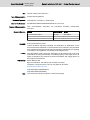
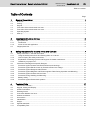

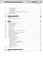
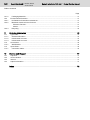

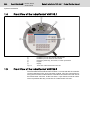

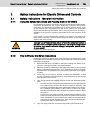


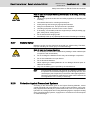
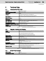

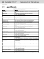


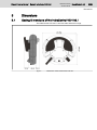
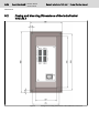


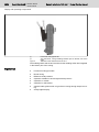
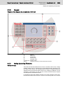


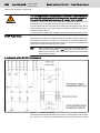
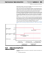
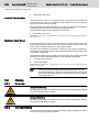
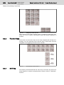


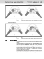
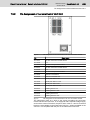
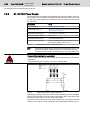
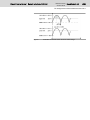
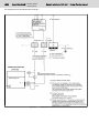


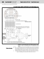


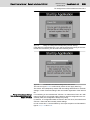


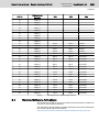
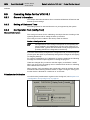

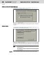

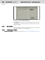


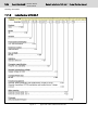


![[Download] azionamenti-hcs01](http://vs1.manualzilla.com/store/data/006141009_1-1242967de3765f3b826dc0b688197751-150x150.png)