1
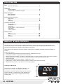
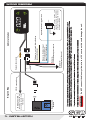
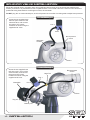
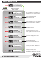
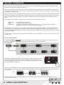
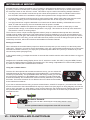
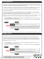
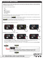
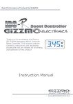
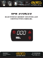
GFB
Electronic boost controller
instruction manual
MENU
SCRAMBLE
BOOST
Go Fast Bits P/L
P.O. Box 1017
Riverwood NSW 2210
Australia
Ph: +61 (0)2 9534 0099
Fax: +61 (0)2 9534 3999
Email: [email protected]
Web: www.gfb.com.au
contents
Intro
About the G-Force II
2
Installation
Wiring Diagram
Solenoid Valve Installation Diagram
3
4
Menu Navigation
Menu Structure
Boost Presets
5
6
Setting the Boost Pressure
Duty Cycle
Gain
Sensitivity
7
8
9
Controller Functions
Scramble Boost
Overboost
Peak Hold
Display Setting - Units of Pressure
Input Setup
Colour Settings
10
11
11
12
12
13
Additional Info
Tips
Troubleshooting
Tech
Warranty
14
15
16
16
about the g force ii
The GFB G-Force II boost controller is designed to bring on boost as fast and accurately as possible on a
turbocharged vehicle. It incorporates an advanced and unique boost control strategy that allows the user fine
control over the peak boost, rise rate, and closed-loop correction.
The G-Force II also features a new user interface, making menu navigation and setup as fast and simple as
possible.
Features at a glance:
?
6 individually programmable boost preset memories, selectable on-the-fly
?
Closed-loop correction - helps prevent boost variations
?
New scramble boost strategy - increase or decrease boost for a certain amount of time at the push of a button
?
Overboost protection - shuts down the solenoid and flashes a warning if boost goes too high
?
Peak hold display
?
Real-time boost/vacuum gauge display - in BAR, kPa, or PSI
?
External input - can be used to activate scramble or select boost memories remotely
?
Adjustable button colours - tie in with the car’s existing lighting
91.5mm
Installing the Head Unit
Alternatively, with its thin profile (18.5mm), the G-Force II
can be mounted on a vertical face of the dashboard, or
stood up on its edge using the supplied double-sided
mounting tape.
2 - intro
MENU
53.5mm
The G-Force II casing is a ½ DIN size, allowing to be
mounted into one half of a standard stereo slot.
SCRAMBLE
BOOST
3 - installation
1/8” I.D. vacuum hose
Red wire +12V switched power source
Blue wire - External input
(see notes below, and
pages 12 & 14 for details)
Yellow wire - not used, future features
(see notes below)
Black wire Vehicle ground (chassis)
Loom
Vacuum hose joiner
MENU
Remote trigger button (not
supplied). Use any switch, button
or sensor that grounds the blue
wire when activated
WARNING! Do NOT connect the blue or yellow wire to a 12V source as this could damage the unit.
If either the blue or yellow wire are not used, simply cut or bundle them and make sure they are insulated.
The yellow wire currently has no purpose, it is intended for use with future features.
BOOST
SCRAMBLE
Optional Remote Trigger Circuit
Vehicle Interior
The external input can be used as a remote trigger simply by connecting it to any kind of switch, button, or programmable ECU output
that grounds the blue wire to the vehicle earth when activated. For ideas on different ways to use the external input, see page 14. Once
connected, the purpose of the external input must be configured within the “INPUT” sub-menu within the menu (see page 12).
Boost Control
Solenoid
To intake manifold use small Tee to tap into
an existing vacuum hose
if necessary
Engine Bay
wiring diagram
solenoid valve installation
Mount the solenoid valve in a position away from significant heat sources (such as the exhaust manifold and
turbine), and where it is protected from rain or splashed water. The unused outlet of the solenoid valve should be
positioned facing downwards to avoid ingress of dust, dirt and water.
DO NOT plug the un-used solenoid port, as this will prevent the controller from being able to adjust boost pressure.
Internal Wastegate
Screw the two supplied hose
tails into ports 2 and 3 of the
solenoid valve, and connect
the ports to the correct
locations as shown using the
supplied 3/16” hose.
Port 2
Port 3
Boost pressure
source
Wastegate
actuator
Turbo
External Wastegate
Screw the two supplied hose
tails into ports 1 and 2 of the
solenoid valve, and connect
the ports to the correct
locations as shown using the
supplied 3/16” hose.
Wastegate
Boost pressure
source
Large Tee
Port 1
Port 2
Turbo
Top port
Bottom port
4 - installation
menu structure
RUNNING MODE
(Normal controller operation)
Hold
MENU
To exit from the
menu at any point
To enter menu and advance
through the options
Duty Cycle
Display scrolls “dUtY”, followed
by “PEAK”. Details see page 7.
Gain
Display scrolls “gAIn”.
For more details, see page 8.
Sensitivity
Display scrolls “SEnS”.
For more details, see page 9.
Scramble Seconds
Display scrolls “SCr SEC”.
For more details, see page 10.
Overboost
Display scrolls “OVErbSt”.
For more details, see page 11.
Peak Hold
Display scrolls “PEAK”.
For more details, see page 11.
Display Units
Display scrolls “dISP”.
For more details, see page 12.
Input Setup
Display scrolls “INPUt”.
For more details, see page 12.
Button Colours
Display shows “COL.”.
For more details, see page 13.
5 - Menu navigation
Controls peak boost pressure.
Duty Cycle is adjustable from 0-100%, where 0 results
in the lowest boost pressure, and 100 is the highest.
Controls how fast the turbo spools up.
Gain is adjustable from 0-100, where 0 is the slowest
spool-up, and 100 is the fastest.
Controls how strongly the G-Force II resists changes in
boost pressure. Sensitivity is adjustable from 0-100,
where 0 results in no correction and, and 100 is the
Sets the number of seconds that the scramble boost
feature remains on when activated.
Adjustable from 0-100 seconds.
Turns off the solenoid in the case of over boost.
The Overboost setting is adjustable from 0-345kPa, 03.45bar, or 0-50psi, depending on which display units
are currently in use.
Turns the Peak Hold display function on and off.
When set to “ON”, the display shows the peak boost
value for 3 seconds after the manifold drops to vacuum.
Changes the display pressure units.
Can be set to kPa (default setting), BAR, or PSI.
Changes the function of the external input wire.
“OFF” turns off the remote input, “PrE” jumps to the
next boost preset, and “SCr” activates scramble feature.
Allows changes to the button colours.
The display does not change, but pressing “up” will alter
the “scramble/preset active” button colour, and pressing
down” will alter the normal “background” button colour.
boost presets
The G-Force II has 6 boost presets (P1-6), each of which can be individually programmed and accessed quickly
on-the-fly using a variety of different methods.
There is an additional preset called “SCr”, which is the preset that is activated when the scramble feature is used.
See page 10 for more info on scramble. “SCr” can be set up and used just like any other preset, so effectively there
are actually 7 presets in total.
Whilst 7 presets may be more than most people will use, there are a number of ways they can be utilized to further
fine-tune your boost to suit whatever it is you plan to do with your car, whether it be for street, drag, circuit, or drift.
See the suggestions listed on page 14 for ideas on different ways the boost presets (and other features) can be
used.
Each boost preset consists of 3 adjustments that can be used to tailor the boost curve:
·
·
·
Duty cycle Gain Sensitivity -
controls peak boost pressure
controls how fast the boost rises
controls the strength of the closed-loop correction – i.e. how strongly the controller
attempts to correct boost pressure changes and taper
Note that it is not necessary to set or use Gain and Sensitivity to set the boost pressure - for simplicity, boost can
be controlled only by Duty Cycle if so desired. Usually, a well-matched turbo/wastegate/engine will respond very
well with only Duty Cycle adjustments, however these features are helpful when your goal is to extract the most out
of your turbo system.
For best results, these three adjustments should be made in the order listed above, as each correction ties into the
previous one.
To select boost presets:
From Running Mode, Tap BOOST (or the remote trigger button if installed and configured, see page 3 and 12 for
details) to sequentially scroll through the boost presets from SCr-1-6, as shown below:
Running Mode
Tap
BOOST
Whenever the down/boost button or remote trigger is used to change the preset,
the down/boost button changes colour as an additional visual indication that a
preset change has occurred. The colour that the button changes to can be set in
the Colour MENU (see page 13).
MENU
SCRAMBLE
BOOST
Whenever the manifold is in vacuum and a new boost preset is selected, the display will show the boost preset
number, followed by the target boost pressure associated with that preset before returning to Running Mode after a
few seconds:
Boost preset
Running mode
Peak boost
E.g.
If the manifold is in boost, the display stays as a boost gauge, but the down/boost button still changes colour to
indicate a preset change.
6 - MENU navigation
duty cycle
BEFORE adjusting duty cycle, it is HIGHLY recommended that you first set
up the OVERBOOST feature (see page 11 for more information).
STOP
OVERBOOST is a “global” setting that will turn off the solenoid if boost
pressure exceeds the overboost setting (regardless of the boost preset
currently being used), which is intended to prevent damage to your engine
if the controller is adjusted incorrectly or accidentally.
The factory default setting is 100kPa (1 bar, 14.5psi).
The duty cycle setting controls the peak boost pressure, and is adjustable from 0-100%, where 0 represents the
lowest possible boost pressure your turbo system is capable of running (commonly referred to as “gate pressure”),
and 100 represents the highest. Note however that the controller is very unresponsive to changes when using duty
cycles less than 10% or greater than 90%, and therefore all boost presets are factory set to 10%.
See page 16 for a detailed description of what duty cycle is and how it works.
The duty cycle must be increased carefully and incrementally until you arrive at a setting that results in the target
boost pressure that you want to achieve.
1.
Select the boost preset that you want to adjust (see page 6).
2.
Tap “MENU” once to navigate to “Duty Cycle” - the screen will scroll “DUtY”, followed by the current duty
cycle setting, then “PEAK”, followed by the current peak boost recorded for that duty cycle setting.
3.
Tap the up/down buttons to adjust the duty cycle setting - it is safest to start at 10 so you can see the
minimum boost pressure, and make adjustments from there. NOTE: whenever you make adjustments to
the duty cycle, the “PEAK” boost value will clear to 0.
4.
Do NOT exit the menu
5.
Drive the car to record the peak boost – you will need to ensure that you perform a full- throttle run,
sweeping through the engine's peak torque RPM in the highest gear possible/practical to ensure the
controller records the true peak boost - you can do this as many times as you like until you’re sure you’ve
recorded the true peak boost. If you exceed the overboost value, the peak value will be cleared back to 0.
6.
Adjust the duty cycle accordingly (higher for more boost), then drive the car again (using the same method
as above to ensure consistency) to record the new peak boost.
7.
Continue to make adjustments until you achieve your desired peak boost pressure.
8.
When done, tap “MENU” to move on to GAIN, or hold “MENU” to exit. In either case, the duty cycle setting
and peak boost will be saved to the boost preset that you are currently in. The G-Force II will use the
stored peak boost as the target, and will use this target boost for the GAIN and SENSITIVITY features. If
you do not record a peak boost, the controller will still work, but GAIN and SENSITIVITY will not be able to
make any closed-loop corrections.
9.
Repeat this procedure for any other boost presets you may wish to set up.
NOTES:
?
0-10% duty means the solenoid valve is completely off, and 90-100% duty is fully on - to run boost pressures that cannot be
achieved with 0-100% duty cycle, you must physically change the turbo and/or wastegate - it is not possible to achieve boost
pressures outside of this range with the controller alone (or any controller for that matter).
?
It is not unusual for duty cycle values of less than 10% to make little change to the boost pressure, because the solenoid
valve response is non-linear. That is why the default duty cycle in all boost presets is 10%. You may find you need to adjust it as
high as 25% before you start to notice an increase in boost pressure - this is completely normal.
?
The higher the required duty cycle to achieve your target boost, the harder boost is to control - it is more likely that boost will
taper at high RPM and vary more according to atmospheric conditions with duty cycles in the upper end of the range.
?
For the reason above, it may be difficult to run high and low boost pressures that are vastly different from each other, for
example a low boost of 10psi and a high boost of 30psi simply may not be possible with the turbo and wastegate.
7 - setting the boost pressure
Gain
The Gain setting controls how fast boost pressure rises during spool-up.
NOTE: the gain setting requires a target “peak” boost to be set up in duty cycle. If you adjust duty cycle
without performing a boost run, the target boost will be 0 and gain will not function.
Gain is adjustable from 0-100, where 0 gives a factory-like spool up, which is basically the “natural” rise rate of the
turbo system. A setting of 100 will attempt to make boost rise as fast as the turbo system is capable of by
delaying the opening of the wastegate.
Of course it may then be tempting to assume that the obvious setting would simply be 100 for fastest possible
spool-up, but in practice this will almost certainly result in an overshoot (boost spike), because the wastegate
needs time to move and curb the turbo’s enthusiasm!
Every turbo system is different, and some will handle more gain without noticeable spiking, whilst others may
require a lower gain setting. Note that gain is optimum when boost pressure rises as fast as possible WITHOUT
spiking.
1.
Make sure duty cycle has first been adjusted and peak boost set, as per page 7.
2.
Select the boost preset that you want to adjust (see page 6), then navigate to the “Gain” menu (tap
“MENU” twice from Running Mode) – the screen will scroll “gAIn”, followed by the current gain setting
(default is 0).
3.
Set gain to 0, then drive the car in such a way that the boost pressure rises as fast as possible – this is
usually done by flooring the throttle at relatively high RPM.
4.
Now increase the gain setting using the up/down buttons, then drive the car again (using the same method
as above to ensure consistency).
5.
Note how the boost spool-up rate changes, and continue to adjust the gain setting to achieve the desired
boost response. If you notice that boost starts to overshoot the target, reduce the gain setting until boost
pressure hits the target consistently without overshooting.
6.
When done, tap “MENU” to move on to Sensitivity, or hold “MENU” to exit. In either case, the Gain setting
will be saved to the boost preset that you are currently in.
7.
Repeat this procedure for any other boost memories you may wish to set up.
NOTE: the Gain function is automatically turned off when making boost pressure adjustments (in Duty Cycle) so
that you can record the true peak boost, however the Gain setting will be reactivated when you return to Running
Mode.
You may find it necessary to re-adjust the Gain setting after changing the boost pressure.
8 - setting the boost pressure
Sensitivity
The Sensitivity setting controls a closed-loop correction factor that attempts to correct any difference between the
actual boost and the target boost pressure. This is useful on a turbo that tends to drop boost pressure as RPM
rises (boost taper), and can also help pull boost pressure up to the target when it is rising very slowly (such as in a
very high gear).
NOTE: the sensitivty setting requires a target “peak” boost to be set up in duty cycle. If you adjust duty
cycle without performing a boost run, the target boost will be 0 and sensitivity will not perform closed-loop
corrections.
Boost taper is common on small factory turbos, because they are typically sized for mid-range response rather than
top end power, and as such they tend to “run out of puff” at high RPM.
The Sensitivity feature can help curb the boost drop-off. It is adjustable between 0-100, where 0 results in no
closed-loop correction at all, and 100 is the strongest correction possible.
If the setting is too high, the boost pressure might start getting unstable, so this is another setting that should be
tested experimentally to find what works best for your turbo.
If you notice that boost pressure falls away at high RPM and you want to try to correct this behaviour, follow the
steps below:
1.
Make sure duty cycle has first been adjusted and peak boost set, as per page 7. It is not necessary to set
gain for sensitivity to work, but if you do plan to use gain you should set it before adjusting sensitivity.
2.
Select the boost preset that you want to adjust (see page 6), then navigate to the “Sensitivity” menu (tap
“MENU” three times from Running Mode) – the screen will scroll “SEnS”, followed by the current Sensitivity
setting (default is 0).
3.
Drive the car in such a way that the boost pressure falls off at high RPM, and take note of the highest
pressure drop and the RPM, e.g. boost falls from 18psi at 5000RPM to 15psi by 7000RPM.
4.
Now increase the Sensitivity setting using the up/down buttons, then drive the car again (using the same
method as above to ensure consistency).
5.
Note how the boost taper rate changes, and continue to adjust the Sensitivity setting to achieve the desired
result. If you notice that boost starts to become unstable (i.e. oscillates or goes up and down rapidly),
reduce the sensitivity setting until stable boost pressure is achieved. It may not always be possible to
completely eliminate boost taper depending on how severe it is, but this setting will at least ensure that
everything the turbo system is capable of is being delivered.
6.
When done, tap “MENU” to move on to the next menu item, or hold “MENU” to exit. In either case, the
Sensitivity setting will be saved to the boost preset that you are currently in.
7.
Repeat this procedure for any other boost memories you may wish to set up.
NOTE: the Sensitivity function is automatically turned off when making boost pressure adjustments (in Duty Cycle)
so that you can record the true peak boost, however it will be reactivated when you return to Running Mode.
There are limits to what the G-Force II can do with the turbo and wastegate – if the duty cycle setting is already
quite high, there is not much adjustment left for the controller to make if boost drops off – once the closed-loop
corrections reach 100% duty cycle, there's nothing more the controller can do as this is the turbo system's limit.
Because of this, it may not always be possible to completely eliminate boost taper, although it should be able to be
reduced at the very least. The only solution (in this case) to hold more boost is a larger turbo, different wastegate
spring, or both.
9 - setting the boost pressure
scramble boost
Scramble boost is a feature that allows you to increase (or decrease) boost pressure for a certain amount of time
by clicking a remote-mounted button or switch (see page 3 for details on how to wire up a remote button/switch), or
the “scramble” button on the G-Force’s screen. This feature may be useful in the following example situations:
?
In a drag-race, the controller could be set up with a lower boost pressure in order to maintain traction off the
line. Scramble could then be activated to a higher boost pressure when enough traction is available.
?
In circuit racing, scramble could be used as a “push-to-pass” setup, where a little extra boost pressure could
help during overtaking, but is not desired throughout the entire race for the longevity of the engine.
?
In a high-powered car it might be desirable to run lower boost for better drivability, civilised behaviour on the
street, or better fuel economy, then use scramble when full power is needed.
Use scramble to LOWER boost pressure to safe-guard the engine, such as when a water spray or water
?
injection bottle is empty, or the ambient temperature is very high - this could even be set up to be automatic if
connected to a sensor or warning output.
The G-Force II uses a unique scramble approach where it jumps to a dedicated boost preset when activated,
instead of simply adding extra boost. This method offers much more flexibility in how it can be used because you
can tailor the duty cycle, gain, and closed-loop correction specifically to suit the purpose that you intend to use the
scramble feature for. In this way, you can raise OR lower boost pressure, as well as change the spool-up rate and
closed-loop correction, which cannot be done with traditional scramble methods.
Setting up scramble:
When activated, the scramble feature jumps from whatever boost preset you are currently in to the boost preset
called “SCr”. Therefore, you need to set the desired duty cycle, gain, and sensitivity parameters that you want when
scramble is activated. To do this, you simply set up the boost preset called “SCr” just as you would for any of the
other 6 boost presets (see pages 6-9).
In the scramble setting, you adjust the number of seconds that scramble remains active after the button or trigger is
released.
Navigate to the scramble setting (display shows “SC.S”, which then scrolls “SCr. SEC”) using the “MENU” button,
then use the up/down buttons to adjust the scramble time. This setting is adjustable from 0-99 seconds (default is
0). When 0 is selected, the scramble feature is inactive.
Using the scramble feature:
Once the SCr boost preset and scramble seconds are set up, you can activate the
scramble feature at any time by tapping the up/scramble button, or grounding the
remote input (see below). The up/scramble button will change colour (you can alter
the colour that it changes to in the Colour menu, see page 13) and scramble will
activate immediately. The scramble timer however will only start when you release
the button. The button will remain lit in a different colour to indicate that scramble is
active until the timer finishes.
MENU
SCRAMBLE
BOOST
If you want to activate scramble using a remote-mounted button, switch ECU output etc, you need to first connect
the blue remote wire to the button/switch/ECU output you want to use (see page 3 for wiring diagram), then set the
input to “SCr” (see page 12, “Input Setup”). Once you have done this, the remote input will replicate the function of
the up/scramble button, and the up/scramble button will also change colour in the same way to indicate when
scramble is active.
Hold
MENU
To exit
Tap
MENU
Scramble Seconds
Display scrolls “SCr SEC”, followed by the current setting (default is “OFF”).
Use the up/down buttons to adjust time from OFF-100 seconds.
Tap
MENU
10 - controller functions
overboost
Overboost is a safety feature that will turn off the solenoid and flash the buttons red if the boost pressure exceeds
the limit set in this menu option. This will help prevent damage to the engine if an accidental or incorrect adjustment
is made to the controller, which is particularly helpful during boost setup.
The factory default value for overboost is 100kPa (1bar, or 14.5psi). Overboost is adjustable between 0 - 345 kPa
(0 - 3.45 bar, 0 - 50 psi). If you do not want to use overboost, simply set it to the maximum boost pressure.
This is a “global” controller setting, and is therefore the same for every boost memory, and is shown in the same
pressure units as the display.
It is strongly advised that Overboost is set BEFORE making boost pressure adjustments. You should choose a
maximum limit slightly above your intended peak boost pressure. E.g. if you intend to run say 120 kPa maximum
boost, set the Overboost for approximately 130kPa so it doesn’t trigger prematurely.
NOTE: The Overboost feature CANNOT protect against a boost overshoot caused by a stuck wastegate or popped
wastegate/solenoid hose connection, since these kinds of failures are outside of the G-Force II’s control.
?
From Running Mode, use the “MENU” button to navigate to the Overboost setting (display scrolls “OVEr bSt”)
?
Use the “UP/DOWN” buttons to adjust the value
?
Tap “MENU” to save and move on to the next menu item, or hold “MENU” to save and exit to Running Mode
Hold
Tap
MENU
MENU
To exit
Overboost
Display scrolls “OVErbOOSt”, followed by the current setting (default is “OFF”).
Use the up/down buttons to adjust the value from 0-345 kPa (0-3.45bar, 0-50psi)
Tap
MENU
peak hold
Peak Hold (when turned on) will momentarily display the highest boost pressure recorded during a boost run.
Whenever the manifold starts to see positive boost pressure, Peak Hold will start recording and will store the
highest boost pressure value. When the manifold drops back into vacuum, the peak boost will be displayed on the
screen for 3 seconds. Each time the manifold goes into boost, Peak Hold is cleared and starts recording again.
Peak Hold can be set to “ON” or “OFF”.
?
From Running Mode, use the “MENU” button to navigate to the Peak Hold setting (display scrolls “PEAK”)
?
Use the “UP/DOWN” buttons to toggle it on or off
?
Tap “MENU” to save and move on to the next menu item, or hold “MENU” to save and exit to Running Mode
Hold
MENU
Tap
MENU
To exit
Peak Hold
Display scrolls “PEAK”, followed by the current setting (default is “OFF”).
Use the up/down buttons to turn Peak Hold on or off
Tap
MENU
11 - controller functions
display setting - units of pressure
Display allows you to configure the boost gauge display to read boost pressure in kPa (default), BAR or PSI.
Note that when PSI is selected, vacuum is displayed in inHg (inches mercury), which is the same as found on most
psi unit boost gauges.
?
From Running Mode, use the “MENU” button to navigate to the Display setting (display scrolls “dISP”)
?
Use the “UP/DOWN” buttons to select from “KPA” (default), “BAR” or “PSI”
?
Tap “MENU” to save and move on to the next menu item, or hold “MENU” to save and exit to Running Mode
Hold
Tap
MENU
MENU
To exit
Display
Display scrolls “dISP”, followed by the current setting (default is “KPA”).
Use the up/down buttons to adjust the value from kPa, BAR, or PSI
Tap
MENU
input setup
Input Setup allows you to configure the purpose of the external input (blue wire). For information on how to
connect the external input to a button or switch, see the wiring diagram on page 3.
There are three modes for the external input:
?
OFF - no action
?
SCr - the scramble feature is activated when the external input is triggered
?
PrE - scrolls sequentially through the boost pressure memories when triggered (in the same way as pressing
the “down” button in running mode)
?
From Running Mode, use the “MENU” button to navigate to the Input setting (display scrolls “INPUt”)
?
Use the “UP/DOWN” buttons to select from “OFF” (default), SCr, or PrE
?
Tap “MENU” to save and move on to the next menu item, or hold “MENU” to save and exit to Running Mode
Hold
MENU
Tap
MENU
To exit
Input
Display scrolls “INPUt”, followed by the current setting (default is “OFF”).
Use the up/down buttons to select from OFF, Scr, or PrE
Tap
MENU
12 - controller functions
Colour settings
Colour allows you to configure the button colours - both the normal “background” colour (i.e. when not pressed),
and also the “feature active” colour, which is the colour a button turns when either scramble or preset features are
activated (see pages 6 and 10).
There are 7 colour options available:
?
Red
?
Green
?
Blue
?
Aqua (green/blue)
?
Purple (red/blue)
?
Yellow (green/red)
?
Off (no light)
“Off” is provided as an option, which could be used for example if you don’t want the buttons lit at night, but still
want a visual indication when scramble is activated.
Within the Colour menu, Tap BOOST to scroll through the “background” colour options - you will see the buttons
change colour as you do this - the display screen will not change.
Tap SCRAMBLE to scroll through the “activated” colour options - you will see the button you are tapping briefly change
colour, indicating what all buttons will change to when activated.
Example 1: Changing “background” colours
MENU
MENU
MENU
SCRAMBLE
SCRAMBLE
SCRAMBLE
BOOST
BOOST
BOOST
Example 1: Changing “feature active” colours
MENU
MENU
MENU
SCRAMBLE
SCRAMBLE
BOOST
BOOST
SCRAMBLE
BOOST
?
From Running Mode, use the “MENU” button to navigate to the Colour setting (display shows “COL”)
?
Use the “UP/DOWN” buttons to make your selection as described above
?
Tap “MENU” to save and move on to the next menu item, or hold “MENU” to save and exit to Running Mode
Hold
MENU
Tap
MENU
To exit
Colour
Display shows “COL.”
Use the “up” button to adjust the “background” button colour
Use the “down” button to adjust the “pressed” button colour
Tap
MENU
13 - controller functions
Tips
Here are some handy suggestions for different ways you can set up and use the features on your G-Force II.
If you set the “INPUT” menu item to “SCr” (scramble), then you can use the external input wire to trigger scramble
in a variety of different ways to achieve different outcomes.
For example, you can connect the external input wire to:
?
Steering wheel button - easy access to use as a “push-to-pass” system. You can drive normally on low boost
and access high boot immediately when required (or when you have traction). If you set the scramble seconds
to 0, it will return to low boost as soon as the button is released, or you can have it time out after a few seconds.
?
Throttle switch - using a micro-switch on the throttle pedal (like a “kick-down” switch), or a configured output from
an aftermarket ECU, you can make the scramble feature activate when the throttle is floored, for an “automatic”
version of “push-to-pass” - i.e. you get high boost when you need it simply by flooring the throttle.
?
Brake/handbrake switch - you can activate high boost after a certain amount of time has passed during a drag
race to aid traction off the line. In this case, you would set the scramble boost preset to a lower boost setting for
launch, and set the scramble seconds to whatever time you want to engage the high boost setting (i.e. when
scramble times out). So when you are staging, the brake pedal/handbrake is held and scramble is active on a
low boost preset. When the brake is released and the run begins, the scramble timer starts and will turn off after
the chosen amount of time, reverting back to the original (high) boost preset.
?
Toggle switch - use a toggle (on/off) switch instead of a momentary button (press and release) to keep scramble
activated as long as the switch is on. This method gives you easy high/low boost selection, perhaps useful if you
need to fill the car with low octane fuel and the toggle switch gives you a good visual reminder that you’re in low
boost.
?
Warning light or programmable output from ECU - if you have other warning devices such as a knock light, low
water level (for water injection/intercooler spray), high intake air/water/oil/transmission temperature, you could
use such a warning light or programmable ECU output to activate scramble to a lower boost pressure to help
protect the engine.
If you set the “INPUT” menu item to “bOOSt” (boost preset selection), every time you activate the external input,
the controller jumps to the next boost preset.
This can be used to set up a kind of “boost-by-gear” feature for drag racing situations. You would connect the
external input to a clutch switch or gear selector switch in such a way that it triggers with each gearshift. Then,
when you stage your car, manually select boost preset 1 using the buttons on the G-Force II, and then each time
you shift gears after your launch, the external input on the clutch or gear selector will activate the next boost preset.
Since there are 6 boost presets, you can tailor the peak boost, rise rate and taper for each gear.
14 - Additional info
Troubleshooting
Boost pressure remains the same regardless of the duty cycle setting:
Turn the ignition off, then on again and listen for the solenoid to click rapidly for about 1 second. If you can’t hear it click
on power up, check the wiring loom to the solenoid valve.
If the solenoid does click rapidly on power up, check the hose connections to the solenoid valve and wastegate - make
sure the un-used solenoid valve port is not plugged, and that the boost pressure and wastegate hoses are connected to
the right ports.
Check the controller is receiving full battery voltage. If it is powered off a low voltage supply, the display will work but the
solenoid will not.
The peak boost pressure always seems to be higher than the target that was originally set:
The car may not have been driven in a way that achieved the “true” peak boost whilst duty cycle was being set up. Go
back into Duty Cycle and either reduce the duty cycle value so that peak boost comes down to where you want it, or
leave the duty cycle alone and drive the car again to learn the “true’ peak boost.
Reduce the Gain setting
Boost spiking should not be confused with boost taper (see
below). Boost taper often looks similar to spiking in low gears
because the RPM increases so quickly.
Boost pressure
Boost pressure spikes (overshoots the target):
RPM
Reduce the Sensitivity setting
If the closed-loop taper correction is set too high, the boost may
fluctuate rapidly up and down, which is a sign that the system is
going “unstable”. It means the correction is too strong, and whilst a
weaker setting will eliminate the instability, boost will likely still
drop off a little because the turbo is nearing its limits (see boost
taper below).
Boost pressure
Boost pressure oscillates significantly:
RPM
This is a sign that the turbo system is operating beyond its efficient
limits. Either the turbo is too small to hold high boost to redline, or
the wastegate spring is too soft. If you are using a duty cycle of
more than 70%, it’s possible that a stronger wastegate spring and
lower duty cycle will hold a more stable boost pressure.
Boost pressure
Boost tapers off even with a high Sensitivity setting
RPM
This is called boost creep, which is a result of the wastegate not
being large enough. It may hold boost stable for some of the rev
range, but at high RPM it is wide open and not flowing enough to
prevent boost from rising further. At this point the G-Force II can do
no more, the only solution is a larger wastegate.
Boost pressure
Boost pressure starts to increase significantly at high RPM:
RPM
15 - Additional info
Tech
Duty Cycle - what the heck is it?
Duty cycle refers to how the solenoid valve is actually controlled. The G-Force II boost controller outputs a signal to
the solenoid valve that rapidly pulses it on and off about 30 times a second (0.033 seconds per cycle) to bleed air
from the wastegate, and duty cycle alters how long it is on for each cycle, and how long it is off.
For example, a duty cycle of 25% means that the solenoid valve is pulsed ON for 25% of each cycle, and OFF for
75% of the cycle. A 25% duty cycle output from the G-Force to the solenoid valve is illustrated opposite:
The higher the duty cycle,
the longer the solenoid is
pulsed on each cycle, which
bleeds more air from the
wastegate actuator, resulting
in a higher boost pressure.
1 cycle
(0.033 seconds)
“ON” period
(0.008 seconds)
“OFF” period
(0.025 seconds)
Duty Cycle limits
Pulsing the solenoid at 0% duty cycle means that all of the pressure gets to the wastegate, which is effectively the
same as having no boost controller, meaning the turbo will run the minimum pressure (aka “gate” pressure)
possible.
Running the solenoid at 100% duty cycle prevents ALL of the pressure from getting to the wastegate, which is
effectively the same as removing the hose from the wastegate altogether, which results in the highest boost
pressure the turbo is capable of supplying.
Why can’t I just dial-in how much boost I want instead of fiddling with duty cycle?
Fair question. Unfortunately, the G-Force II (or any boost controller for that matter) doesn’t know what boost
pressure your specific turbo/wastegate/engine/weather conditions/etc will return for a given duty cycle - there
simply is no formula that says “for this turbo on that car, “X”% duty cycle will give “Y”psi of boost”.
The controller NEEDS to know this relationship between duty cycle and resulting boost pressure, because when
boost is rising quickly, it must pulse the solenoid at the correct duty cycle BEFORE the boost reaches the target
boost pressure. If it doesn’t know the correct duty cycle, it cannot do this.
The reason it must pulse the solenoid before boost reaches the target is because there is always a small delay
between the controller making a change to the duty cycle, and the wastegate (and therefore boost pressure)
responding to the change. This delay means that if the controller simply waited until the boost pressure reached the
target and then responded accordingly, boost pressure would overshoot the target.
Therefore, the only way to determine the duty cycle/boost relationship is through trial-and-error, by starting at a low
duty cycle, reading the resulting boost pressure, and increasing it until you reach the desired boost.
Once the G-Force II knows the duty cycle that results in the target boost pressure, it can then make changes to the
duty cycle to compensate for small variations in boost (when a value for “Taper” has been entered).
warranty
All products manufactured or distributed by Go Fast Bits P/L are subject to the following Limited Express
Warranties, and no others:
For a period of one year from and after the date of purchase of a new Go Fast Bits product, Go Fast Bits warranties
and guarantees only to the original purchaser/user that such a product will be free from defects of material and/or
workmanship in the manufacturing process. Go Fast Bits, at its sole discretion, shall replace or repair a defective
product. This express warranty shall be inapplicable to any product not properly installed or properly used by the
purchaser/user or to any product damaged or impaired by external forces. This is the extent of warranties available
on this product. Go Fast Bits shall have no liability whatsoever for consequential damages following from the use of
any defective product or by reason of failure of any product. Go Fast Bits specifically disclaims and disavows all
other warranties express or implied including, without limitation, all warranties of fitness for a particular purpose,
warranties of description, warranties of merchantability, trade usage or warranties of trade usage.
16 - Additional info