1
contents
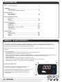
Intro
About the G-Force II
2
Installation
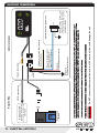
Wiring Diagram
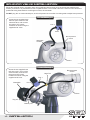
Solenoid Valve Installation Diagram
3
4
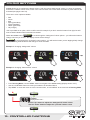
Menu Navigation
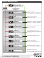
Menu Structure
Boost Presets
5
6
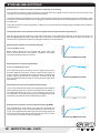
Setting the Boost Pressure
Duty Cycle
Gain
Sensitivity
7
8
9
Controller Functions
Scramble Boost
Overboost
Peak Hold
Display Setting - Units of Pressure
Input Setup
Colour Settings
10
11
11
12
12
13
Additional Info
Tips
Troubleshooting
Tech
Warranty
14
15
16
16
about the g force ii
The GFB G-Force II boost controller is designed to bring on boost as fast and accurately as possible on a
turbocharged vehicle. It incorporates an advanced and unique boost control strategy that allows the user fine
control over the peak boost, rise rate, and closed-loop correction.
The G-Force II also features a new user interface, making menu navigation and setup as fast and simple as
possible.
Features at a glance:
?
6 individually programmable boost preset memories, selectable on-the-fly
?
Closed-loop correction - helps prevent boost variations
?
New scramble boost strategy - increase or decrease boost for a certain amount of time at the push of a button
?
Overboost protection - shuts down the solenoid and flashes a warning if boost goes too high
?
Peak hold display
?
Real-time boost/vacuum gauge display - in BAR, kPa, or PSI
?
External input - can be used to activate scramble or select boost memories remotely
?
Adjustable button colours - tie in with the car’s existing lighting
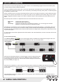
91.5mm
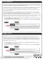
Installing the Head Unit
Alternatively, with its thin profile (18.5mm), the G-Force II
can be mounted on a vertical face of the dashboard, or
stood up on its edge using the supplied double-sided
mounting tape.
2 - intro
MENU
53.5mm
The G-Force II casing is a ½ DIN size, allowing to be
mounted into one half of a standard stereo slot.
SCRAMBLE
BOOST