1
MORPHEUS
Operation Manual
© 1993 E-mu Systems, Inc.
All Rights Reserved
• FI420 Rev. C
Manual - Riley Smith
E-mu World Headquarters
E-mu Systems, Inc. U.S.A.
P.O. Box 660015
Scotts Valley, CA USA
95067–0015
Telephone: 831-438-1921
Fax: 831-438-8612
Europe, Africa, Middle East
E-mu Systems, Ltd.
Suite 6, Adam Ferguson
House
Eskmills Industrial Park
Musselburgh, East Lothian
Scotland, EH21 7PQ
Telephone: 44-31-653-6556
Fax: 44-31-665-0473
Important Notice:
In order to obtain warranty service on your Morpheus unit, the serial number sticker must
be intact and you must have a sales receipt or other proof of purchase. If there is no serial
number sticker on Morpheus, please contact E-mu Systems at once.
This product is covered under one or more of the following U. S. patents: 3,969,682;
3,986,423; 4,404,529; 4,506,579; 4,699,038; 4,987,600; 5,013,105; 5,072,645;
5,111,727 and foreign patents and/or pending patents. Morpheus is a registered trademark of E-mu Systems, Inc.
PRINTED AND MADE IN THE USA
WARNING: READ THIS FIRST!
IMPORTANT SAFETY INSTRUCTIONS
Use in countries other than the U.S.A. may require the use of a different line
cord or attachment plug, or both. To reduce the risk of fire or electric shock,
refer servicing to qualified service personnel. To reduce risk of fire or electric
shock do not expose this product to rain or moisture.
GROUNDING INSTRUCTIONS
In this document, whenever the
word “Morpheus” is mentioned
we are referring to the
Morpheus Synthesizer by E-mu
Systems, Inc.
This product must be grounded. If it should malfunction or break down,
grounding provides a path of least resistance for electric current, reducing the
risk of electric shock. This product is equipped with a cord having an equipment-grounding conductor and a grounding plug. The plug must be plugged
into an appropriate outlet properly installed and grounded in accordance
with all local codes and ordinances.
DANGER
Improper connection of equipment grounding conductor can result in the
risk of electric shock. Check with a qualified electrician or service personnel
if you are in doubt as to whether the product is properly grounded. Do not
modify the plug provided with this product — if it will not fit the outlet,
have a proper outlet installed by a qualified technician.
CAUTION
If the Morpheus (model number 9053), is rack mounted, a standard 19-inch
open frame rack must be used.
This symbol is intended to alert
the user to the presence of
important operating and
maintenance (servicing)
instructions in the literature
accompanying the appliance.
USER-MAINTENANCE INSTRUCTIONS
1. Morpheus should be kept clean and dust free. Periodically wipe the unit
with a clean, lint free cloth. Do not use solvents or cleaners.
2. There are no user lubrication or adjustment requirements.
3. Refer all other servicing to qualified service personnel.
INSTRUCTIONS PERTAINING TO A RISK OF FIRE, ELECTRIC SHOCK, OR INJURY TO PERSONS
WARNING; When using electric products, basic precautions should
always be followed, including the following:
This symbol is intended to alert
the user to the presence of
uninsulated dangerous voltage
within the product's enclosure
that may be of sufficient
magnitude to constitute a risk o
electric shock to persons.
1. Read all instructions before using Morpheus.
2. To reduce the risk of injury, close supervision is necessary when Morpheus
is used near children.
3. Do not use Morpheus near water — for example near a bathtub, washbowl,
kitchen sink, in a wet basement, on a wet bar, or near or in a swimming
pool.
i
SAVE THESE INSTRUCTIONS
4. Morpheus should be situated so that its location or position does not
interfere with its proper ventilation.
5. Morpheus should be located away from heat sources such as radiators, heat
registers, fireplaces, stoves, or ovens.
6. Morpheus should only be connected to a power supply of the type described in the operating instructions and as marked on the product.
7. This product, in combination with an amplifier, headphones, and speakers, may be capable of producing sound levels that could cause full or
partial hearing loss or damaged equipment. Do not operate for long
periods of time at high volume levels or at a level that is uncomfortable.
Additionally, care must be taken when programming any of the filters
contained herein using extreme operating parameters. This action could
also produce signals which result in unacceptable high sound levels as
noted previously. If you experience any hearing loss or ringing of the ears
consult your physician.
8. Morpheus may be equipped with a polarized line plug (one blade wider
that the other). This is a safety feature. If you are unable to insert this plug
into the outlet, do not defeat the safety purpose of the plug. Contact an
electrician to replace your obsolete outlet.
9. The power supply cord of Morpheus should be unplugged from the outlet
when left unused for a long period of time.
10. Care should be taken so that objects do not fall and liquids are not spilled
into the enclosure of Morpheus through openings.
11. The product should be serviced by qualified service personnel when:
A. The power supply cord has been damaged; or
B. Objects have fallen, or liquid has been spilled into the product; or
C. The product has been exposed to rain; or
D. The product does not appear to operate normally or exhibits a
marked
change in performance; or
E. The product has been dropped or the enclosure damaged.
12. All servicing should be referred to qualified service personnel.
SAVE THESE INSTRUCTIONS
ii
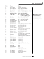
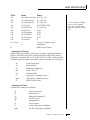
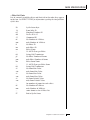
CONTENTS
INTRODUCTION & BASIC SETUP
1
Introduction ...........................................................................................
Getting Started ......................................................................................
Connection Instructions ......................................................................
Background - About Sampling ..........................................................
BASIC OPERATION
Main Controls ......................................................................................
Selecting MIDI Channels ...................................................................
Selecting Presets/Hyperpresets .........................................................
Adjusting Volume & Pan Position ...................................................
Memory Card .......................................................................................
Midimap Selection ..............................................................................
Multi-Timbral Operation ...................................................................
Playing the Demo Sequences ............................................................
MASTER MENU
Enabling the Master Menu ...............................................................
Master Tune .........................................................................................
Transpose .............................................................................................
User Key Tuning ..................................................................................
Global Bend .........................................................................................
Global Velocity Curve ........................................................................
MIDI Mode ...........................................................................................
MIDI Mode Change ............................................................................
MIDI Program Change Map ............................................................
MIDI Controller Assign ......................................................................
MIDI Footswitch Control .........................................................
Send MIDI Data ..................................................................................
Sysex Packet Delay .................................................................
Proteus Sysex .........................................................................
Auto Select ............................................................................
Compare Mode ......................................................................
Viewing Angle ......................................................................................
MIDIMAP MENU
3
4
5
9
11
12
14
14
14
15
15
16
16
17
19
19
19
20
20
20
22
22
23
24
24
24
25
26
26
26
26
27
The Midimap ....................................................................................... 29
Enabling the Midimap Menu ........................................................... 30
Midimap Select ...................................................................... 30
Midimap Name .................................................................... 31
Program to Channel Assign .................................................. 31
iii
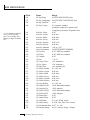
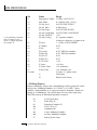
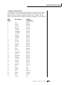
CONTENTS
MIDIMAP MENU (cont)
Volume, Pan & Output Mix .....................................................
MIDI Enables ........................................................................
Bank Select ............................................................................
Program Map Select ..............................................................
FX A .....................................................................................
FX B .....................................................................................
FX Amount ............................................................................
FX Output Select ....................................................................
Save Midimap .......................................................................
EFFECTS SECTION
Where are the Effects? ............................................................
Effects Output Routing ...........................................................
Morpheus Effects Bus Architecture ..........................................
Effect Programming Instructions ..............................................
Reverb ...................................................................................
Stereo Flanger .......................................................................
Stereo Phaser .........................................................................
Stereo Chorus ........................................................................
Stereo Delay ..........................................................................
Stereo Cross Delay .................................................................
Stereo Echo............................................................................
“B” Effects .............................................................................
Stereo Fuzz ............................................................................
Ring Modulator .....................................................................
HYPERPRESET MENU
The Hyperpreset ..................................................................................
Enabling the Hyperpreset Menu .............................................
Hyperpreset Name ................................................................
Preset to Zone Assignment .....................................................
Zone Volume and Pan ...........................................................
Zone Key Range ....................................................................
Zone Velocity Range ..............................................................
Zone Velocity Offset ...............................................................
Zone Transpose ....................................................................
Zone Pitch Tune....................................................................
Hyperpreset Portamento Mode..............................................
Free-Run Function Generator .................................................
Save Hyperpreset ...................................................................
iv
31
33
33
34
34
35
35
36
36
37
39
40
40
41
42
46
48
49
50
51
52
53
54
55
57
59
59
60
60
61
61
62
63
63
63
64
64
66
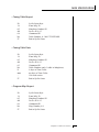
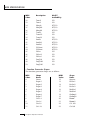
CONTENTS
PRESET PROGRAMMING
67
Starting to Program ..............................................................
Modulation ..........................................................................................
Modulation Sources ...........................................................................
Footswitch Modulation ..........................................................
Midipatch..............................................................................
Envelope Generators ..........................................................................
Low Frequency Oscillators ................................................................
Function Generators ..............................................................
Filter Modulation ...................................................................
Parametric Filters ...................................................................
The Morpheus Filter ...............................................................
The Z-Plane Filter ....................................................................
Another View ...........................................................................
Morpheus Signal Flow ...........................................................
Note-On Modulation Control .................................................
Realtime Modulation Control .................................................
Key Number ...........................................................................
Velocity Curves ......................................................................
MIDI Realtime Controls ..........................................................
PRESET MENU
Enabling the Preset Menu ....................................................
Preset Name ........................................................................
Primary Instrument ..............................................................
Secondary Instrument ..........................................................
Volume ................................................................................
Pan .....................................................................................
Key Range ...........................................................................
Primary Key Range ..............................................................
Secondary Key Range ...........................................................
Transpose ............................................................................
Coarse Pitch Tuning.............................................................
Fine Pitch Tuning .................................................................
Alternate Envelope On/Off ...................................................
Primary Alternate Envelope Parameters................................
Secondary Alternate Envelope Parameters ............................
Double + Detune .................................................................
Sound Delay ........................................................................
Sound Start .........................................................................
69
70
71
72
72
73
75
76
84
87
88
89
92
93
94
95
96
96
97
99
101
102
102
102
103
103
103
104
104
105
105
105
105
106
106
106
107
107
v
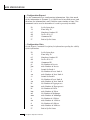
CONTENTS
PRESET MENU (cont)
Sound Reverse......................................................................
Nontranspose ......................................................................
Loop Enable .......................................................................
Loop Offset ..........................................................................
Solo Mode ...........................................................................
Solo Mode Priority ..............................................................
Portamento Rate ................................................................
Portamento Shape ..............................................................
Portamento Mode...............................................................
Crossfade Mode ..................................................................
Crossfade Direction ..............................................................
Crossfade Balance and Amount ..........................................
Cross-switch Point ..............................................................
Primary Filter Type ..............................................................
Secondary Filter Type ..........................................................
Filter Level ...........................................................................
Morph Offset ......................................................................
Filter Frequency Tracking .....................................................
Filter Transform 2 ...............................................................
Filter Reverse ......................................................................
Auxiliary Envelope ..............................................................
LFO 1 & 2 - Shape & Amount..............................................
LFO 1 & 2 - Rate, Delay & Variation ....................................
Function Generator 1 and 2 .................................................
Note-On Modulation Control ..............................................
Realtime Modulation Control ..............................................
Footswitch Control ..............................................................
Pitch Bend Range................................................................
Pressure Amount ..................................................................
MIDI Controller Amount .....................................................
Velocity Curve ......................................................................
Keyboard Center ..................................................................
Keyboard Tuning ................................................................
Mix Select ...........................................................................
Save Preset ..........................................................................
vi
107
108
108
108
109
110
110
110
111
111
112
112
113
113
113
113
114
114
115
116
116
117
117
118
122
123
124
124
124
124
125
126
126
127
127
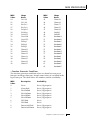
CONTENTS
COPY MENU
Enabling the Copy Menu .....................................................
Copy Preset .........................................................................
Copy Layer ..........................................................................
Copy Filter ...........................................................................
Copy LFO ...............................................................................
Copy Function Generator .....................................................
Copy Auxiliary Envelope ......................................................
Copy Note-On Control .........................................................
Copy Realtime Control .........................................................
Copy Hyperpreset ................................................................
Copy Zone .............................................................................
Copy Free-Run Function Generator.......................................
Copy Midimap .....................................................................
Copy Channel ......................................................................
Copy Effects .........................................................................
Copy Program Change Map..................................................
Copy Bank ...........................................................................
STEP-BY-STEP
Forward .................................................................................
Editing Presets .....................................................................
Starting From Scratch ..........................................................
The Instrument ......................................................................
Volume ..................................................................................
Pan ........................................................................................
Transpose ..............................................................................
Coarse Tuning .......................................................................
Fine Tuning ...........................................................................
Alternate Volume Envelope ....................................................
Anatomy of an Envelope .......................................................
Sound Delay ..........................................................................
Sound Start ...........................................................................
Application: Sound Splicing...................................................
Time to Save? ........................................................................
LFO Modulation ....................................................................
Modulating Modulators ........................................................
The Morpheus Filter ...............................................................
Just Do It ...............................................................................
Filter Filosophy ......................................................................
Morphology ...........................................................................
129
131
131
132
132
132
133
133
133
133
134
134
134
134
135
135
135
136
137
139
139
140
140
141
141
141
142
142
143
144
145
145
146
147
147
150
151
152
154
157
vii
CONTENTS
Using Morpheus with a Sequencer......................................... 158
More Advanced Sequencing .................................................. 159
REFERENCE SECTION
Factory RAM Presets - Bank 0 ................................................
Factory ROM Presets - Bank 1................................................
Instrument Listing..................................................................
B3 Wave Diagrams ................................................................
Percussion Instrument Locations ...........................................
Z-Plane Filter Descriptions .....................................................
Loop Offset Sample Locations................................................
Function Generator Curves ....................................................
Function Generator, LFO & Envelope Specifications ..............
Technical Specifications .........................................................
MIDI Implementation Chart ..................................................
MIDI Specifications ................................................................
MIDI SysEx Tutorial ...............................................................
INDEX
viii
161
162
163
164
169
170
174
211
214
222
223
224
225
251
255
INTRODUCTION
& BASIC SETUP
Chapter 1: Basic Setup
1
2
Morpheus Operation Manual
INTRODUCTION
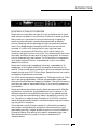
MORPHEUS Z-PLANE SYNTHESIZER
Morpheus is a completely new type of music synthesizer which represents a major landmark in the evolution of electronic sound synthesis.
Many electronic instruments involve the technology of sampling,
where sounds are digitally recorded and played back at different
pitches. Sampling has the advantage of highly accurate and realistic
sound. One disadvantage of sampling is that once the sounds are
recorded, it is difficult to change them in any significant way.
Morpheus introduces the Z-Plane filter, which has the ability to
smoothly change its function over time. This ultra-powerful device can
accurately simulate the resonance of musical instruments, the human
voice or create entirely new timbres. The Z-Plane filter is composed of
up to eight complex filters for unprecedented control over subtle
aspects of the sound.
Morpheus contains eight megabytes (internally expandable to 16
megabytes) of the highest quality 16 bit samples as the basis for its
sounds. These sounds can be combined or spliced, modulated and then
shaped through one of 197 Z-Plane filters. Sampled sounds can now be
re-shaped and expressively controlled.
The 16 bit sound samples are arranged into 256 preset locations, 128 of
which are user-programmable. 128 user-programmable Hyperpresets
allow ultra-flexible keyboard mapping of presets. The optional memory
card lets you create an expandable library of your favorite presets and
hyperpresets.
Morpheus features two studio-quality effects processors with 28 different effects to choose from. Hyperpresets allow you to have up to 32
different sounds on the keyboard at one time in any desired arrangement. Sounds can be placed side by side or layered with velocity control. The ability to respond multi-timbrally to all 16 MIDI channels
makes Morpheus ideally suited for multitrack sequencing and composing using a MIDI sequencer.
Other features include 3 stereo outputs for individually processing
sounds (also configurable as 6 polyphonic submixes with fully programmable panning), integral sends and returns to allow the addition
of external effects units without the need for a separate mixer, user
definable alternate tuning, and of course, an extensive MIDI
implementation.
Chapter 1: Basic Setup
3
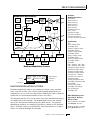
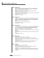
GETTING STARTED
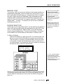
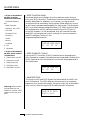
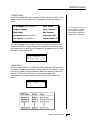
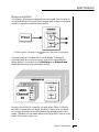
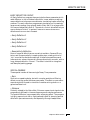
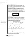
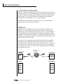
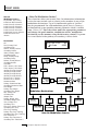
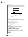
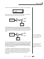
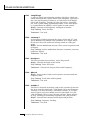
In it's most basic form, Morpheus is organized as shown in the diagram below. Complete acoustic instrument samples and electronically
created sounds are used as raw material to form Presets.
The Preset is a complete set of all program functions and combinations for a complete Morpheus sound. Each preset consists of one or
two Instruments. An Instrument is a complete set of samples or a
digital waveform which covers the entire keyboard range. An instrument can be assigned to each of the Primary and Secondary layers of
the preset.
The primary and secondary layers of the preset are essentially two
instruments with complete modulation controls. The memory is organized into banks of 128 programmable RAM presets, unalterable ROM
presets and Hyperpresets.
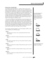
RAM Presets can be
moved, erased or modified as
esired.
ROM Presets cannot be
moved or altered unless they
re first copied to a RAM
ocation.
Hyperpresets are groups
f presets arranged on the
eyboard to form splits or
ayers.
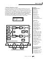
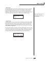
A Hyperpreset is a combination of up to sixteen presets arranged
either side by side on the keyboard (to create a keyboard split) or on
top of each other (to create a denser sound). Each preset in a
hyperpreset is assigned to a keyboard Zone, with an associated key
range, volume, pan, tuning and transpose setting. In addition, each
zone can be assigned to a velocity range so that different presets can
play depending on the key velocity. There are 128 Hyperpreset locations available to store your own custom keyboard setups.
Memory Card - Allows
ou to easily load and save
dditional Presets and
Hyperpresets.
4
Morpheus Operation Manual
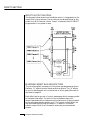
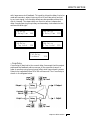
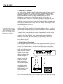
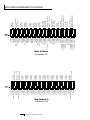
CONNECTION INSTRUCTIONS
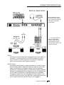
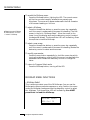
SETUP #1 BASIC SETUP
▼ The headphone output
monitors the main outputs
only. The submix outputs do
NOT feed into the headphone output.
• • • If Morpheus does not
seem to be responding
correctly, make sure that
both Morpheus and your
MIDI controller are set to the
same MIDI channel.
MIDI In
Morpheus is controlled by MIDI messages received at the MIDI In
connector. Connect the MIDI In of the Morpheus to the MIDI
Out connector of a MIDI controller such as a MIDI keyboard,
MIDI wind controller or MIDI guitar controller.
Audio Outputs
Morpheus is a high quality, stereo audio device. In order to reproduce its wide dynamic range and frequency response, use a high
quality amplification and speaker system such as a keyboard
amplifier or home stereo system. A stereo setup is highly desirable
because of the added realism of stereophonic sound. Headphones
can be used if an amplifier and speaker system is not available.
Plug stereo headphones into the headphone jack located on the
left side of the front panel. The Right Main output jack serves as a
mono output when the Left Main plug is not plugged in.
Chapter 1: Basic Setup
5
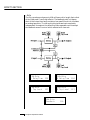
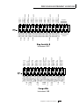
CONNECTION INSTRUCTIONS
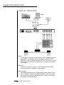
SETUP #2 STUDIO SETUP
MIDI In
In this setup, Morpheus is controlled by MIDI messages received
at the MIDI In connector which have been routed by a MIDI
switcher. The MIDI switcher allows any MIDI controller such as a
MIDI keyboard, MIDI wind controller or a computer to be easily
connected.
MIDI Out
The MIDI Out jack is normally used to transmit MIDI System
Exclusive data to a computer or other device.
Audio Outputs
Morpheus has three sets of programmable stereo outputs; Main,
Sub 1, and Sub 2. Specific Morpheus presets (or MIDI channels)
can be routed to one of these stereo pairs in order to be further
processed or mixed separately.
6
Morpheus Operation Manual
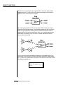
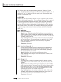
CONNECTION INSTRUCTIONS
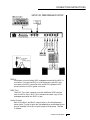
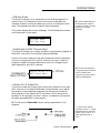
SETUP #3 PERFORMANCE SETUP
MIDI In
Morpheus is controlled by MIDI messages received at the MIDI In
connector. Connect the MIDI In of Morpheus to the MIDI Out
connector of a MIDI controller such as a MIDI keyboard, MIDI
wind controller or MIDI guitar controller.
MIDI Thru
The MIDI Thru jack is used to connect additional MIDI devices
onto the MIDI chain. MIDI Thru transmits an exact copy of the
messages received at the MIDI In jack.
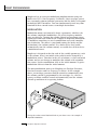
Audio Outputs
Each of the Sub 1 and Sub 2 output jacks on the Morpheus are
stereo jacks. The tip of each jack (accessed when a standard phone
plug is inserted) is the left or right output of that group. The Sub
1 outputs
Chapter 1: Basic Setup
7
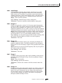
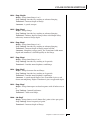
CONNECTIONS
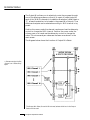
bypass the internal effects section. The Sub 2 outputs are fed from the
effects section. If a stereo plug is inserted, the Ring of the stereo plug
serves as a signal Return which sums into the Main outputs.
Therefore, the Sub 1 and Sub 2 jacks can serve as effect sends and
returns in order to further process selected instruments and then
return them to the main mix.
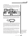
The diagram shows the Sub 1 and Sub 2 jacks being used as send/
returns in order to further process selected Morpheus presets without
using the effects bus on the mixing board. In a pinch, the effect returns could also be used to sum additional instruments into the main
outputs.
Morpheus Output Section
The Sub 1 and Sub 2 jacks can be used as effect returns to the Main Outputs.
POWER UP!
The power switch is located on the right side of the front panel.
Morpheus and its MIDI controller may be turned on in any order.
When power is applied, the liquid crystal display will light, indicating
that Morpheus is operating. You may have noticed that there is no
110/220 Volt power selector switch on Morpheus.
Morpheus automatically switches itself for 110 or 220 Volt
operation.
8
Morpheus Operation Manual
BACKGROUND
ABOUT SAMPLING
Morpheus utilizes digital recording of acoustic sounds for the basis of
each Instrument. This is similar to a tape recorder except that inside
the Morpheus, the sounds are permanently recorded on digital
memory chips.
Sound and instrument waveforms are first sampled into the Emulator
III, our top of the line, 16 bit stereo digital sampler. After the sounds
and waveforms have been truncated, looped and processed, they are
permanently encoded into the Morpheus ROM (Read Only Memory)
chips.
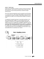
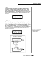
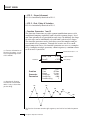
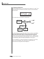
Conceptually, the sampling process is very simple, as shown in the
Basic Sampling System diagram. As a sound wave strikes the diaphragm of a microphone, a corresponding voltage is generated. To
sample the sound, the voltage level is repeatedly measured over time
and the corresponding data values are stored in memory. To play the
sound back, the numbers are read back out of memory, modified by
the Z-plane filter, converted back into voltages, then amplified and fed
to a speaker which converts the voltage back into sound waves. Of
course, playing back 32 channels at different pitches tends to complicate matters, but this is basically how it works.
Chapter 1: Basic Setup
9
10
Morpheus Operation Manual
BASIC
OPERATION
Chapter 2: Basic Operation
11
MAIN CONTROLS
Volume Control
This is the master volume control for all audio outputs. Note: For
maximum dynamic range, set this control at full level.
Card Slot
The card slot accepts RAM and ROM cards containing additional
presets, hyperpresets and midimaps.
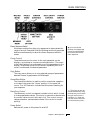
Master Menu Select Button
The Master menu contains global parameters which affect the
entire machine. The LED to the left of the button indicates that
you are in the Master menu.
Midimap Menu Select Button
A Midimap is a set of parameters used to configure Morpheus to
other MIDI gear such as a sequencer or keyboard setup. The 16
Midimaps contain digital effects setting as well as assignments of
presets/hyperpresets to MIDI channels. An LED to the left of the
button indicates that you are working in the Midimap menu.
Preset Menu Select Button
The Preset menu is used when you want to create or modify a
preset. The LED to the left of the button indicates that you are
working in the Preset menu. To Compare an edited preset with the
unedited version, simply exit Preset Edit mode. The stored preset
will be heard whenever the main screen is selected. Changing the
preset will erase the edited version.
Hyperpreset Menu Select Button
The Hyperpreset menu is used to place presets at certain locations
on the keyboard to create custom keyboard layouts. The LED to
the left of the button indicates that you are working in the
Hyperpreset menu.
12
Morpheus Operation Manual
MAIN CONTROLS
Demo Sequence Select
Morpheus contains four play-only sequences to demonstrate the
range of sounds. Press and hold the Midimap and the Hyperpreset
buttons simultaneously to select the Demo Sequence selection
screen.
▼ You must hold the
Midimap and Hyperpreset
buttons for approximately
two seconds to start the
demo sequences.
Cursor Control
These buttons move the cursor to the next parameter on the
display in a clockwise or counter-clockwise direction. (The cursor
is the little flashing line underneath one of the parameters in the
display.) Press either cursor control button repeatedly until the
cursor is underneath the desired parameter.
Copy Button
The copy menu allows you to copy selected groups of parameters
between Presets, Hyperpresets, and Midimaps.
Home/Enter Button
The Home/Enter button is used to confirm a particular operation
or to return the cursor the “Home” position in the upper left
corner. The LED flashes to indicate that Morpheus is waiting for
your response.
Data Entry Control
The data entry control is a stepped, variable control which is used
to change parameter values. The control increments or decrements
the current value one unit with each click. This control incorporates acceleration (values advance faster if the control is turned
quickly).
••• The cursor can also be
moved bidirectionally using
the data entry control while
the right cursor button is
held down. (i.e. Press and
hold the cursor button and
turn the data entry knob.)
Power Switch
Switches AC power to Morpheus On and Off.
Chapter 2: Basic Operation
13
BASIC OPERATION
MIDI Activity LED
Indicates that MIDI data is being received.
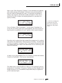
MIDI CHANNEL SELECTION
Press the cursor key repeatedly until the cursor is underneath the
channel number. (The cursor is the little flashing line underneath one
of the parameters in the display.) Rotate the data entry control to
select MIDI channel 01-16. As the channel is changed, the display will
change to show the preset/hyperpreset, volume and pan associated
with the displayed channel.
• • If Morpheus is not
esponding properly or plays
he wrong preset, make sure
hat both Morpheus and
our MIDI controller are set
o the same MIDI channel
nd that the MIDI Volume is
urned up.
or more information about
MIDI, see MIDI Realtime
ontrols on page 97.
C01 VOL127 PAN=P
0
000 Preset Name
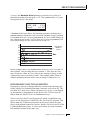
PRESET/HYPERPRESET (PROGRAM) SELECTION
Press the cursor key repeatedly (or press Home/Enter) until the cursor
is underneath the program number. A Program is a Preset or a
Hyperpreset. As the data entry control is rotated, the program number
and name will change. The displayed program will be assigned to the
displayed MIDI channel. Programs are arranged into banks of 128, as
shown in the diagram at left. Banks can be selected independently of
the program number by pressing the Home/Enter button while turning the data entry knob.
C01 VOL127 PAN=P
0
000 Program Name
↔
↔
MIDI Channel Parameters
Preset/Hyperpreset Name
CHANNEL VOLUME
Press the cursor key repeatedly until the cursor is underneath the
volume value. Rotate the data entry control to select volume 000-127.
(This is the same parameter as MIDI volume control #7, and changes
made over MIDI will be shown in the display.)
•• Channel Pan should
ormally be set to “P” unless
ealtime control of panning is
esired. If Pan is set to “0”, a
tereo preset will play in
mono.
14
CHANNEL PAN
Press the cursor key repeatedly until the cursor is underneath the pan
value. Rotate the data entry control to select pan values -7 to +7 or
“P”. When “P” is selected, the pan value specified in the preset is
selected. Any other value will override the pan parameter in the preset. (This is the same parameter as MIDI pan control #10, and changes
made over MIDI will be shown in the display.)
Morpheus Operation Manual
BASIC OPERATION
MEMORY CARD
The memory card is a convenient method of saving and transferring
presets and hyperpresets. Insert the card firmly into the slot on the
front panel with the label facing up. Press the eject button to release
the card. A RAM card stores 128 presets, 128 hyperpresets and 16
midimaps. RAM cards may be Write-Protected by moving the little
switch on the end of the card. If a memory card is NOT inserted, the
display reads “ --noCard-- ” for banks 3 & 4 and the list of selectable
midimaps shrinks to 16.
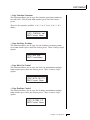
MIDIMAP SELECTION
A Midimap is a set of parameters which can be used as a pre-sequence
setup, storing the program and other parameters for each MIDI channel or it could be used as an “Effects Preset”, since each Midimap
stores a complete effects setup. There are 16 Midimaps in Morpheus
and an additional 16 Midimaps can be stored on a memory card.
RAM Cards can be used to
store your own presets,
hyperpresets and midimaps.
ROM Cards contain prerecorded presets,
hyperpresets and midimaps.
You cannot save data to a
ROM card.
▼ RAM Cards need to be
initialized before they are
first used. They display will
prompt you to initialize a
blank card.
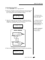
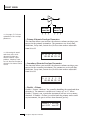
To Select a Midimap
Press the Midimap key, lighting the LED. The current screen will
be the one most recently selected since powering up Morpheus.
The first screen in the menu is Midimap Select. Move the cursor
to the lower line and use the data entry control to select one of
the 16 Midimaps. The Home/Enter LED will be flashing. Press the
Home/Enter key to load the new Midimap.
MIDIMAP SELECT
M00 -defMIDIMap-
••• The “current Midimap”
is remembered on powerdown, even though you may
not have saved it. This
effectively gives you a total o
17 internal Midimaps.
Simply scrolling through the list DOES NOT change the Midimap.
You must move the cursor down to line two and press Enter. Try
out the different Midimaps and notice that the effects change with
each one.
Chapter 2: Basic Operation
15
BASIC OPERATION
MULTI-TIMBRAL OPERATION
Multi-timbral operation means that the Morpheus can play more
than one sound at the same time. To access multiple presets on
different MIDI channels simultaneously, follow these instructions:
1. Set the MIDI mode to MULTI-Mode, using the MIDI mode
function in the Master menu (page 22).
2. Decide which MIDI channels you wish the Morpheus to receive, and turn “All Messages” Off for the MIDI channels that
you DO NOT want Morpheus to receive using the MIDI Enables in the Midimap menu (page 33). Turning “All Messages
Off” turns that channel Off.
If you do not turn any channels Off, Morpheus will
receive all 16 MIDI channels simultaneously!
3. Select the desired preset or hyperpreset for each of the MIDI
channels you wish the Morpheus to receive using the
Preset/Hyperpreset -> MIDI Channel selection screen in the
Midimap menu (page 31).
4. Save the Midimap using the last screen in the Midimap menu.
5. Morpheus will now respond multi-timbrally on the MIDI
channels you have specified.
6. The effects can be programmed and each MIDI channel assigned to an effects bus if so desired. The volume and pan
position can be adjusted for each MIDI channel in the
Midimap Volume and Pan screen. Remember to SAVE the
Midimap or all of your work will be LOST when you select
another Midimap.
PLAYING THE DEMO SEQUENCES
Morpheus contains a play-only sequencer with 4 different sequences
to give you an idea of what is possible using this amazing instrument.
Press and hold both the Midimap and Hyper buttons. The sequence
will start momentarily. Press the Enter button to stop the sequence.
Press the right cursor button to advance to the next sequence.
Sequences will cycle automatically.
DEMO 1 2 3 4
ENTER=Stop >=Nxt
16
Morpheus Operation Manual
MASTER
MENU
Chapter 3: Master Menu
17
18
Morpheus Operation Manual
MASTER MENU
The Master menu contains functions that affect the overall operation
of Morpheus. For example, changing the Master Tune will change the
tuning of all the presets, not just the one currently displayed.
To enable the Master menu
Press the Master button, lighting the LED. The current screen will
be the one most recently selected since powering up Morpheus.
The Cursor will appear underneath the first character of the
screen heading on line one.
To select a new screen
Press the Home/Enter button or press the Cursor
buttonrepeatedly until the cursor is underneath the screen title
heading. Rotate the data entry control to select another screen.
To modify a parameter
Press the Cursor button repeatedly (or hold the right cursor key
while turning the data entry control) until the cursor is underneath the parameter value. Rotate the data entry control to
change the value.
To return to the main screen
Press the Master button, turning off the LED.
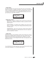
MASTER MENU FUNCTIONS
• Master Tune
Master tune adjusts the overall tuning of all presets so that Morpheus
can be tuned to other instruments. The master tuning range is ± 1
semitone in 1/64th semitone increments. A master tune setting of
“+00” would indicate that the Morpheus is perfectly tuned to concert
pitch (A=440 Hz).
MASTER TUNE
+63
• Transpose
This function transposes the key of Morpheus in half-step intervals.
The transpose range is ± 12 semitones or one octave.
TRANSPOSE
+12 semitones
Chapter 3: Master Menu
19
MASTER MENU
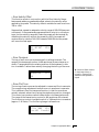
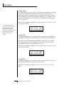
• User Key Tuning
In addition to standard twelve tone equal temperament, Morpheus
contains four additional preset tuning tables (Just C, Vallotti, 19 tone,
and Gamelan) and one user definable tuning. User Key Tuning allows
you to alter the parameters of the user definable tuning stored in
memory. The initial frequency of every key can be individually tuned,
facilitating the creation of microtonal scales. Using the cursor key and
the data entry control, select the key name, the MIDI key number and
the fine tuning. The key name is variable from C-2 to G8. Coarse
Tuning (which also happens to be the MIDI key number) is variable from 0
to 127. The fine tuning is variable from 00 to 63 in increments of 1/64
of a semitone (approx. 1.56 cents). For each preset, the specific tuning
table is selected in the Preset menu.
•• Application: The user
ey tuning can be used to
une individual percussion
nstruments.
▼ It is possible to tune the
itch up so high that the
ange of Morpheus' pitch
hifter is exceeded. If the
itch will not go any higher,
ry using the Transpose
ontrol instead of Coarse
uning.
USER KEY TUNING
Key:C1
036-00
• Global Bend
This function sets the range of the pitch wheel controller (even when
pitch wheel is not routed to control pitch). The maximum pitch bend
range is ± 12 semitones. This function only affects presets which have
their individual pitch bend range set to global.
•• In order for the Pitch
Wheel to control pitch, it
must be routed to this
estination in the Realtime
Modulation Control screen.
GLOBAL BEND
+/- 12 semitones
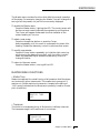
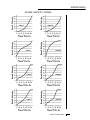
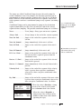
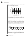
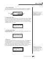
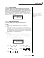
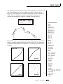
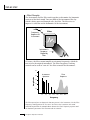
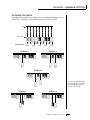
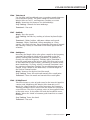
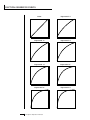
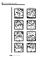
• Global Velocity Curve
Incoming velocity data can be modified by a velocity curve in order to
provide different types of dynamics in response to your playing or to
better adapt to a MIDI controller. This function allows you to select
one of eight global velocity curves or leave the velocity data unaltered
(off). Global velocity curve only affects presets which have their individual velocity curve set to global.
GLOBAL VEL CURVE
8
20
Morpheus Operation Manual
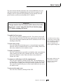
MASTER MENU
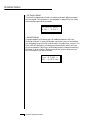
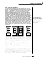
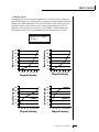
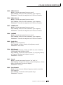
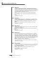
GLOBAL VELOCITY CURVES
Chapter 3: Master Menu
21
MASTER MENU
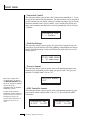
• MIDI Mode
This function selects one of the four MIDI receive modes and the MIDI
system exclusive ID number.
Omni mode
Morpheus responds to note information on all MIDI channels
and plays the preset currently displayed in the main screen.
Poly mode
Morpheus only responds to note information received on the
currently selected MIDI channel (the “basic channel”, displayed
on the main screen) and plays that channel’s associated preset.
Multi mode
Morpheus responds to data on any combination of MIDI channels and plays the specific preset associated with each of the MIDI
channels.
Mono mode
Morpheus responds to data on any combination of MIDI channels but plays each channel monophonically. If a new note on a
channel is played before the last note is released, the envelopes
will not be retriggered. Mono mode is particularly useful with
alternate controllers such as MIDI guitars, etc.
▼ Warning: MIDI Sysex data
will not be transferred
etween two Morpheus units
nless the ID numbers of
oth units match.
Device ID
This function allows an external programming unit to distinguish
between multiple Morpheus units. In the case of multiple
Morpheus units, each unit should have a different device ID
number.
MIDI MODE
Omni
ID
00
•MIDI Mode Change
This function selects whether or not MIDI mode change commands
are accepted or ignored when received over MIDI (see MIDI Mode).
MIDI MODE CHANGE
Disabled
22
Morpheus Operation Manual
MASTER MENU
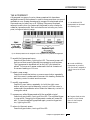
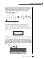
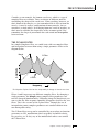
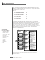
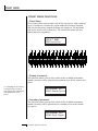
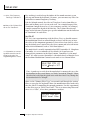
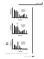
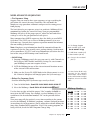
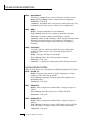
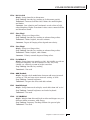
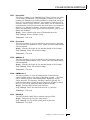
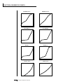
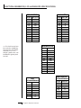
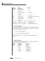
• MIDI Program Change Map
Incoming MIDI program changes can be remapped to a different
numbered preset. This is a handy feature when you want a specific
MIDI program number sent from the master synth to be linked with a
specific preset or hyperpreset on Morpheus. For example, the Program
Change Map could be set to call up preset 12 whenever Morpheus
receives program change number 26. Any preset or hyperpreset in
Morpheus can be mapped to any incoming MIDI program change
number. There are four separate Program Change Maps available. This
feature also allows you to call up presets in any bank, which are not
accessible through a standard MIDI program change. Note: The
Program Map only operates if it is selected in the Midimap
and if the Bank Select function in the Midimap is set to
bank 0.
PROG CHG 0MAP
026 > 012
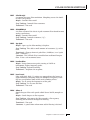
••• The Bank Select function
is located in the Midimap
menu.
#1
••• On some synthesizer
Program 00 is called Program
01 with a corresponding di
ference through all the num
bers.
This chart shows how MIDI preset changes can be re-mapped. In this example,
program changes 10-29 have been re-mapped. All other programs will be selected
normally.
Chapter 3: Master Menu
23
MASTER MENU
•• A few of the standardzed MIDI Controller
umbers are listed below.
- Modulation Wheel or
ever
- Breath Controller
- Aftertouch: Rev 1 DX7
- Foot Pedal
- Portamento Time
- Data Entry
- Volume
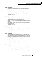
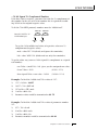
• MIDI Controller Assign
Morpheus allows you to assign up to four realtime control sources
from your MIDI controller. These control sources could be modulation
wheels, data sliders or whatever. In this screen, you set up which
controllers will be received by the Morpheus. What effect the controller will have is programmed separately for each preset. The Morpheus
MIDI controllers are each assigned a letter, A-D. Each controller letter
can be assigned to a MIDI realtime controller from 00-31. Note: If
controller numbers 7 or 10 are selected, they will override the standard MIDI volume and pan control routings. For more information,
see MIDI Realtime Controls in the
Programming Basics section.
- Balance
CONTROLLER# ABCD
01 02 03 04
- Undefined
0 - Pan
1 - Expression
•• A few of the standardzed MIDI switch numbers
re listed below.
4 - Sustain Switch (on/off)
5 - Portamento (on/off)
6 - Sostenuto (on/off)
• MIDI Footswitch Control
Like the MIDI Controllers, 3 MIDI footswitches can be assigned to
MIDI footswitch numbers. Footswitches can be assigned numbers from
64-79. Destinations for the footswitch controllers are programmed in
the Preset menu.
7 - Soft Pedal (on/off)
FOOTSW CTL# 123
64 65 66
9 - Hold Pedal 2 (on/off)
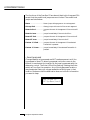
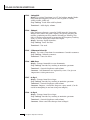
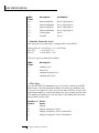
• Send MIDI Data
▼ Warning: When transferng Sysex data from one
Morpheus to another, the ID
umbers of both units must
match.
24
This function will send MIDI System Exclusive data to the MIDI Out
port of Morpheus. The MIDI data can either be sent to a computer/
sequencer or to another Morpheus. Using the cursor key and the data
entry control, select the type of MIDI data you wish to transmit.
SEND MIDI DATA
RAM Presets
Morpheus Operation Manual
MASTER MENU
The Enter LED will be flashing. Press the Enter button to confirm the
operation. To receive MIDI data, simply send the MIDI data into
Morpheus from another Morpheus or your sequencer. The choices are:
To Record MIDI Data into
a Sequencer:
RAM Presets ......................................... Transmits all the user RAM presets.
ROM Presets ................................... Transmits all the factory ROM presets.
2. Place sequencer into
record mode, then Send MIDI
Data.
Card Presets ................................... Transmits all the memory card presets.
To Receive MIDI Data
from a Sequencer:
RAM Hypers ............................... Transmits all the user RAM hyperpresets.
1. Simply play back the
sequence into Morpheus.
Card Hypers .......................... Transmits all the memory card hyperpresets.
RAM MIDI Maps ................................... Transmits all the user MIDI maps.
Card MIDI Maps .................... Transmits all the memory card MIDI maps.
Program Change Maps ............ Transmits all the program change maps.
1. Setup sequencer to receive
system exclusive data.
▼ Warning: Send data
from your sequencer as you
would a regular sequence.
Sending data in one huge
chunk may clog the
Morpheus input buffer.
Master Settings .................... Transmits all parameters in the Master menu
except tuning table, program change map & viewing angle.
The “scratch” Midimap is also transmitted.
Tuning Table ..................................... Transmits only the user tuning table.
All RAM Data ................. Transmits all the user RAM data in the machine.
Individual Program ... Transmits only the specified preset or hyperpreset.
Individual Midimap....................... Transmits only the specified midimap.
Individual Program Change Map Transmits the specified program map.
When Individual Programs, Midimaps or Program Change Maps are
received via SysEx, they are placed in their proper locations.
• Sysex Packet Delay
Errors can sometimes occur when transferring Sysex data from
Morpheus to a computer because the computer cannot process and
store the incoming data fast enough. This function allows you to
change the amount of delay between MIDI Sysex data packets so that
the input buffer of your computer does not overflow. The default
speed is 300 delay units. A setting of “000” allows full speed MIDI
Sysex. If you are having data transmission errors, increase the delay
until the problem disappears.
▼ A Midimap received by
Morpheus does not change
the “scratch” Midimap
unless it is currently selected.
You must select the Midima
for it to be active. See page
159.
••• The Individual Midimaps
and Program Change Maps
are located after the Individual Programs (keep
scrolling).
▼ Turn “Keyboard Thru”
mode OFF on your sequencer
when transferring SysEx data
or a MIDI feedback loop may
result.
SYSEX PKT DELAY
300
Chapter 3: Master Menu
25
MASTER MENU
• Proteus Sysex
When this function is On, Proteus presets can be transferred over
MIDI into Morpheus. It also allows the use of Proteus patch editing
programs. Instrument numbers and parameters which are unique to
Morpheus will, of course, NOT be transferred. This function defaults
to Off to avoid unplanned conflicts with Proteus Sysex transfers.
PROTEUS SYSEX
Off
• Auto Select
When editing a parameter which involves the keyboard, such as a
zone range, the parameter can be automatically selected simply by
playing the keyboard. This is a handy feature for “power programmers”, but can sometimes be confusing. Therefore, Auto-Select can be
turned On or Off. Auto-Select affects the following parameters: User
Key Tuning, Zone Select, Key Range, Midimap, Preset & Hyperpreset
Naming, Cross-switch Point, Keyboard Center.
AUTO-SELECT
Off
• Compare
This function turns the Compare feature (accessed by pressing the
Preset button when editing) On or Off. If Compare is turned On,
changes made via MIDI SysEx will not be heard except when the
Preset menu is enabled.
▼ If Morpheus does not
espond to external preset
ditors, turn the Compare
unction Off.
COMPARE
On
• Viewing Angle
This function allows you to change the viewing angle of the display so
that it may be easily read from either above or below. The angle is
adjustable from +7 to -8. Positive values will make the display easier to
read when viewed from above. Negative values make the display easier
to read from below.
VIEWING ANGLE
+7
26
Morpheus Operation Manual
MIDIMAP
MENU
Chapter 4: Midimap Menu
27
28
Morpheus Operation Manual
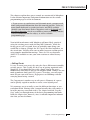
MIDIMAP MENU
THE MIDIMAP
A Midimap is a group of parameters which you might associate with a
specific sequence or song. You can also use the Midimaps as “Effects
Presets” for your favorite effects setups. The Midimap contains all the
pre-sequence setup information, such as the program (preset or
hyperpreset) for each MIDI channel, effects settings, etc. There are 16
Midimaps in Morpheus and an additional 16 can be stored on a
memory card.
••• Midimaps can also be
changed using a SysEx
Parameter Change command. See page 159.
Midimaps are often used with Morpheus connected to an external
sequencer in MULTI mode. Multi mode allows Morpheus to receive
MIDI data on all 16 channels simultaneously. Morpheus can store 16
different Midimaps. The two digital effects processors are also part of
the Midimap.
Chapter 4: Midimap Menu
29
MIDIMAP MENU
To enable the Midimap menu
Press the Midimap button, lighting the LED. The current screen
will be the one most recently selected since powering up
Morpheus. The cursor will appear underneath the first character
of the screen heading on line one.
To select a Midimap
Press the Home/Enter button or press the cursor key repeatedly
until the cursor is underneath the screen title heading. The first
screen in the list is “Midimap Select”. Move the cursor to the
lower line of the display and use the data entry control to select
the desired Midimap. The Home/Enter LED will be flashing. Press
Home/Enter to load the Midimap.
▼ Selecting a new Midimap
will overwrite the “current”
r “scratch” Midimap.
To select a new screen
Press the Home/Enter button or press the cursor key repeatedly
until the cursor is underneath the screen title heading. Rotate the
data entry control to select another screen.
To modify a parameter
Press the cursor button repeatedly (or hold the cursor key while
turning the data entry control) until the cursor is underneath the
parameter value. Rotate the data entry control to change the
value.
To return to Program Select mode
Press the Midimap button, turning off the LED.
MIDIMAP MENU FUNCTIONS
• Midimap Select
This is where you select one of the 16 Midimaps. You can use the
Midimaps to setup a particular sequence or song. Position the cursor
under the Midimap number and use the data entry control to select
the Midimap. The Home/Enter LED will be flashing. You MUST
press Enter to load the Midimap.
MIDIMAP SELECT
M00 Cool FX
30
Morpheus Operation Manual
MIDIMAP MENU
• Midimap Name
This function allows you to name each of the 16 Midimaps with a
name of up to 12 characters. Position the cursor underneath the
character location and use the data entry control to change the character. The keyboard can also be used to select characters.
This screen displays the current Midimap. The Midimap Select screen
is the last screen in the menu.
▼ The Auto-Select feature in
the Master menu must be
turned On in order to use the
keyboard for naming
Midimaps.
MIDIMAP NAME
M15 New Song
• Preset/Hyper to MIDI Channel Assign
This function allows you to assign a preset or hyperpreset (program) to
each MIDI channel for the currently selected Midimap.
Position the cursor under the channel number and use the data entry
control to change the MIDI channel. Position the cursor under the
program number and use the data entry control to change the program assigned to each MIDI channel.
▼ The MIDI channel shown
in the right side of the screen
is NOT the MIDI basic
channel, only the one being
edited in the Midimap.
PRESET/HYPER C01
0
061 Space Wash
• Volume, Pan & Output Mix
This function sets the Volume, Pan Position and Output Mix for each
MIDI channel in the selected Midimap. Volume allows you to adjust
the relative volume between programs. Pan allows you to position
each program in the stereo field. The Volume control acts as an attenuator on the program volume. It cannot increase the volume past
the setting programmed in the program.
▼ The Pan control Overrides the pan value programmed in the
program.
VOL PAN MIX
127 =P FxA
••• Channel Pan should
normally be set to “P” unless
realtime control of panning i
desired. If Pan is set to “0”, a
stereo preset will play in
mono.
C01
Chapter 4: Midimap Menu
31
MIDIMAP MENU
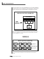
The Output Mix allows you to selectively route the program through
one of the effects processors or direct it to a pair of output jacks (for
each of the 16 MIDI channels). An additional selection called Preset or
“P”, allows the selection to be made in the preset (Mix Output). Thus
effects and outputs can be selected according to MIDI channel or by
preset.
Position the cursor under the channel number and use the data entry
control to change the MIDI channel. Position the cursor under the
volume, pan or mix and use the data entry control to change the
value. The volume and pan values are the same ones shown in the
main screen.
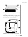
The diagram below shows the function of Output Mix Select.
•• Please note that the Sub
Output is an “Effects Only”
utput.
The Output Mix Select (for each MIDI channel) selects which bus in the Output
Section will be used.
32
Morpheus Operation Manual
MIDIMAP MENU
• MIDI Enables
The MIDI enables allow you to enable or filter out specific MIDI messages on a per-channel basis. MIDI messages that can be filtered include:
All Messages (turns channel off)
Pitch Wheel
Program Change
Mono Pressure
Bank Select
Key Pressure
Volume Control (controller #7)
Controllers A-D
Pan Control (controller #10)
Footswitches 1-3
••• The Channel Pan contro
can be disabled to prevent
incoming MIDI messages
from altering stereo effects
programmed in the presets.
The “All Messages” filter is useful when you have other MIDI devices
connected and do not want Morpheus to respond to the MIDI channels reserved for other devices. Messages will be passed when On and
filtered out when turned Off.
MIDI ENABLES C01
AllMessages
On
• Bank Select
The MIDI specification only allows for 128 presets per MIDI channel.
This function selects which bank of 128 presets will be used for incoming MIDI program change commands. Banks can be set for each MIDI
channel. This function allows you to access all presets and
hyperpresets in Morpheus without using a MIDI Bank Select command.
BANK SELECT
0
C01
Chapter 4: Midimap Menu
33
MIDIMAP MENU
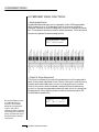
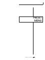
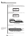
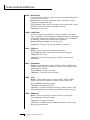
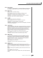
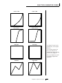
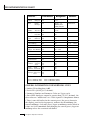
• Program Map Select
There are four Program Maps in Morpheus. Program Maps allow
incoming MIDI program changes to be translated into another number. For example, a program map could be set up so that program
number 12 is selected whenever program change number 26 is received at the MIDI in port. The Program Map Select function allows
you to select one of the four Program Maps to be used in the currently
selected Midimap or turn the Program Map function Off. Note: The
Program Map only operates if it is turned On and the Bank
Select function is set to bank 0.
•• The Program Change
Maps are located in the
Master menu.
PROG CHG MAP
Off
This chart shows how MIDI preset changes can be re-mapped. In this example
program changes 10-29 (darkened area) have been re-mapped. All other programs
will be selected normally.
• FX A
This function allows you to select which effect is active on Effect
Processor A. Processor A effects include several types of reverb as well
as other effects such as delays, chorus, flanger, and phase shifter. Each
effect has one or more adjustable parameters which are accessed by
moving the cursor to the lower line. See the Effects section for detailed
information on these functions.
FXA: Room
Decay Time
34
Morpheus Operation Manual
100
MIDIMAP MENU
• FX B
This function allows you to select which effect is active on Effect
Processor B. Processor B effects include echo, delay, chorus, phase
shifter, distortion and ring modulator. Each effect has one or more
adjustable parameters which are accessed by moving the cursor to the
lower line. See the Effects section for detailed information on these
functions.
FXB:StereoFlange
LFO Rate
050
• FX Amount
This function allows you to adjust the ratio of dry (unprocessed) to
wet (processed) signal coming out of the effect processor. A setting of
100% indicates that all of the signal is being processed by the effect.
The B->A parameter allows you to adjust the amount of effect B which
will be fed through the A effect. If B->A is set to one value above
100%, the word “Only” is displayed and the B amount changes to Off.
This disconnects effect B from the main outputs and routes ALL of
effect B through effect A.
FX AMOUNT A:50%
B->A:0%
B:75%
Chapter 4: Midimap Menu
▼ If the B->A amount is set
to “Only”, no sound will
result if “No Effect” is
selected for effect A
35
MIDIMAP MENU
• FX Output Select
This function selects which pair of output jacks each effect processor
will be routed. This is shown in the diagram on page 32 by the 3-way
switches after each effect processor.
FX OUTPUT SELECT
A:Main B:Sub 1
• Save Midimap
Changes made to a Midimap are not made permanent until the
Midimap is Saved. To save a Midimap, move the cursor to the bottom
line and select one of the 16 locations with the data entry control. The
Enter LED will be flashing. Pressing the Home/Enter switch will confirm the operation. Writing to a Midimap location erases the existing
Midimap in that location. Make sure that the location does not contain information you want to keep.
Save MIDIMAP to
M00 -defMIDIMap-
36
Morpheus Operation Manual
EFFECTS
SECTION
Chapter 5: Effects Section
37
38
Morpheus Operation Manual
EFFECTS BASICS
Where are the Effects?
The effects in Morpheus are separate from the preset. This is similar to
an external effects unit except that the signal path is kept in the digital
domain to maintain excellent sound quality.
The Effects section in Morpheus is located external to the preset in the Midimap
menu.
The effects section is located within the Midimap. There are 16
Midimaps (and 16 more on a memory card) which store different
effects setups. You could think of a Midimap as an Effects Preset
(although they store other parameters as well).
For each of the 16 MIDI channels, you may select: Effect A, Effect B,
the Main Outputs (with no effect), the Sub 1 Output (with no effect),
or you may choose to use the Mix Select programmed as part of the
preset. Therefore you can select effects routings by MIDI channel or by
preset. The choice is up to you.
Chapter 5: Effects Section
39
EFFECTS SECTION
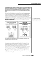
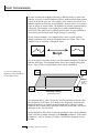
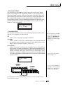
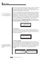
EFFECTS OUTPUT ROUTING
The diagram below shows how the effects section is integrated into the
output jack routing scheme. The mix bus can be selected either by the
preset or by MIDI channel. When “Preset” is selected, the MIX SELECT
programmed in the preset is used.
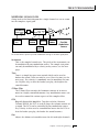
MORPHEUS EFFECT BUS ARCHITECTURE
The two stereo effect processors on Morpheus are designated as A and
B effects. “A” effects contain Reverb and other effects. The “B” effects
do not include Reverbs, but include a host of other great effects which
are listed on page 53.
Each effect has its own set of control parameters which are appropriate
to that particular effect. For both the A and B effects there is an
amount parameter which determines the relative mix of the processed
and unprocessed signals (wet/dry mix). The output of the B effect can
also be routed back through processor A. In addition, the stereo
submix outputs (Sub 1) can be used to externally process selected
presets.
40
Morpheus Operation Manual
EFFECTS SECTION
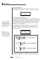
TO PROGRAM AN EFFECT:
1) Press the MIDIMAP button lighting the LED.
2) Slowly turn the data entry knob clockwise until you find the screen
shown below. Select one of the effect processors in the Mix Selection. This selects the input to the effect processors.
VOL PAN MIX
127 =P FXA
••• The diagram on the
previous page illustrates the
function of Mix Select.
C01
3) Set the FX Amount for the A or B effect. This adjusts the ratio of
effected to un-effected signal. B->A allows you to route the output
of effect B through effect A (set the MIX to effect B).
FX AMOUNT A:50%
B->A:0%
B:50%
••• Setting the B->A percent
age to maximum selects
“Only” which disconnects
effect B from the main
outputs and routes all of the
signal through effect A.
▼ If the B->A amount is set
to “Only”, no sound will
result if “No Effect” is
selected for effect A
4) Select the desired Effect and program the appropriate parameters.
FXA:Echo
L Delay Time 255
Chapter 5: Effects Section
41
EFFECTS SECTION
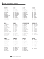
A EFFECTS
Room
Warm Room
Small Rooms 1 & 2
Halls 1, 2 & 3
Chambers 1 & 2
Plates 1 & 2
Early Reflections 1-4
Reverse Early Refl.
Rain & Shimmer
Stereo Flange
Phaser
Stereo Chorus
Delay
Cross Delay
Echo
B EFFECTS
Fuzz
Fuzz Lite
Stereo Flange
Phaser
Stereo Chorus
Delay
Cross Delay
Ring Modulator
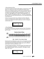
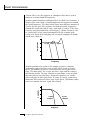
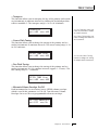
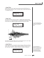
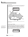
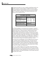
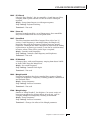
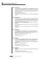
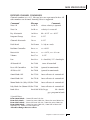
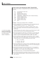
REVERB
Reverberation is a simulation of a natural space such as a room or hall.
The reverb effects in Morpheus simulate various halls, chambers,
rooms and reverberation plates. In addition, there are several other
reverb effects such as Early Reflections and Rain. There is only one
adjustable parameter on the reverbs - Decay Time. Decay time is the
length of time that it takes for the reflected sound from the walls of
the room to die away. In general, the larger the room, the longer the
decay time.
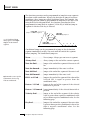
The diagram below breaks down the reverberated sound into its component parts. After an initial pre-delay period, the echoes from the
closest walls or ceiling are heard. These first echoes or the early reflection cluster, vary greatly depending on the type of room. Roughly 20
milliseconds after the reflection cluster, the actual reverberation begins
and decays according to the time set by the decay time parameter.
Floor, Wall &.
Ceiling Reflections
Thousands of
Very Complex
Reflections
42
Morpheus Operation Manual
EFFECTS SECTION
Room programs simulate small rooms with high frequency absorption
caused by drapes and furniture.
Plates simulate plate type reverbs with their tight, dense early reflections and sharp reverb build-up.
Chambers simulate medium sized rooms with hard reflective surfaces.
Hall programs recreate the open, spacious ambience of large concert
halls.
Early Reflection programs consist of the reflection cluster only without the reverb decay. These effects are similar to a multiple tap delay
line and have a single adjustable parameter - Ambience.
The special reverbs Rain & Shimmer are variations of the early reflection programs and consist of a dense group of short echoes followed
by longer echoes.
FXA:Hall 1
Decay Time: 165
Place the cursor underneath the reverb name and use the data entry
control to change the type of reverb. Moving the cursor to the lower
line allows you to change the decay time of the reverb. The decay
times of the reverb programs range from 100-255. The ambience
control of the Early Reflection programs range from 0-100.
• Room
A bright, medium sized room. The apparent source position is fairly
close to the listener. Suitable for use with 100% wet mix setting for
adding ambience.
• Warm Room
This reverb is similar to “Room” with more high frequency absorption,
slightly larger size and a more distant source position.
• Small Room 1
This reverb is also to “Room” with shorter initial reflections, shorter
decay times and higher reflection density, due to the reduced room
size. The apparent source position is closer to the listener.
• Small Room 2
This reverb is a variation of “Small Room 1” with greater high frequency damping and a more distant source position.
Chapter 5: Effects Section
43
EFFECTS SECTION
• Hall 1
Hall 1 is a large, highly reverberant space with auditorium-like acoustics. Like all the Hall programs, “Hall 1” exhibits a warm, distant
ambience with slow reflection density buildup. With the decay parameter set to maximum, “infinite” reverberation effects can be obtained.
Adjustment of wet-dry mix can be used to position the listener from
the “front row” (≈25%) to “back of the balcony” (≈100%).
• Hall 2
This reverb is similar to “Hall 1”, but harder and brighter, with more
pronounced slap echoes that come from parallel reflecting surfaces in
the room. Hall 2 also exhibits a pronounced reverb “bloom” or latereflection buildup. A 50% wet mix creates the optimum “close” distance adjustment.
• Hall 3
Hall 3 is similar to “Hall 2”, but with larger scale stadium-like acoustics. Hall 3 is warmer than Hall 2 (more high frequency damping) and
does not display the obvious early reflections and slap echoes. It also
exhibits a distinct predelay of approximately 100 milliseconds and a
pronounced late reflection buildup both of which contribute to the
impression of a large space. Wet mix values of 10% to 50% are most
appropriate, although a setting of 100% produces an effective cave
simulation.
• Chamber 1
A simulation of a bright, medium-sized chamber reverb or recital hall
with hard walls. Early reflections are very prominent, with high reflection density. Moderately long decays are possible at the maximum
decay setting.
• Chamber 2
Similar to “Chamber 1” but with a much warmer sound. The wet mix
adjustment provides an effective control over the apparent source
location from close (10%) to very distant (100%).
• Plate 1
Simulates a plate reverb unit. Gives a tight, bright, slightly metallic
sound. Reflection buildup is very rapid, with high density. Early reflections are minimized.
• Plate 2
An effect similar to Plate 1, but slightly warmer with less density.
44
Morpheus Operation Manual
EFFECTS SECTION
EARLY REFLECTION GROUP
All Early Reflection programs have a single Ambience parameter which
adds diffusion to the individual reflections. Lower ambience settings
cause reflections to become more discrete, simulating harder reflecting
surfaces. The early reflection programs are simulations of increasingly
large acoustic spaces, from a small studio (Early Refl 1) to a large room
like a sound stage (Early Refl 4). The wet mix control acts effectively as
source distance control. In general, lower mix amounts are more
effective as the room size increases.
• Early Reflection 1
• Early Reflection 2
• Early Reflection 3
• Early Reflection 4
• Reverse Early Reflection
More of a special effect than an acoustic simulation, Reverse ER contains a set of exponentially increasing delay taps, creating a kind of
“zip” sound at low Ambience settings. At maximum ambience and
lower wet mix values, the sound is more authentically acoustic, with a
long, delayed reflection “bloom”. The effect is similar to a large but
well damped parking garage.
SPECIAL REVERBS
These special reverbs all have a single Decay Time parameter.
• Rain
Similar to a repeating delay, but with complex spatial and filtering
effects occurring across the stereo panorama. The effect on percussive
sounds might be likened to a bucket of marbles raining down on a
galvanized steel roof.
• Shimmer
Distantly related to the Rain effect, Shimmer causes input signals to be
progressively diffused in time and space across the stereo panorama.
The spatial diffusion is accompanied by a flanging effect. The program
is highly responsive to left or right-panned inputs. A stunning special
effect with percussive sounds, and especially through headphones.
Chapter 5: Effects Section
45
EFFECTS SECTION
• Stereo Flanger
A flanger consists of a short audio delay line whose output is mixed
together with the original signal. Mixing the delayed and original
signals together results in multiple frequency cancellations creating a
comb filter effect as shown in the diagram below. Since the flanger is a
type of filter, it works best with harmonically rich sounds such as
strings.
The flanging effect was originally created using two tape recorders
playing identical recordings. By exactly synchronizing the two decks
and then slowing the speed of one by grasping the tape reel flanges,
the flanging effect was born.
The flanger in the Morpheus is a stereo device consisting of two separate delay lines controlled by a single set of controls. The block diagram of the flanger is shown below.
46
Morpheus Operation Manual
EFFECTS SECTION
A Minimum Delay control serves to tune the flanger. In other words,
it adjusts the placement of the comb filter notches. The initial delay is
variable from 26 microseconds to 6.5 milliseconds.
FXA:StereoFlange
Min Delay
100
A Low Frequency Oscillator (LFO) varies this initial delay setting,
changing the frequency of the notches and adding animation to the
sound. The LFO Rate controls the rate of change and the LFO Depth
controls how much the delay is changed by the LFO. The LFO adds to
the initial delay time so that with LFO Depth set to 255 the maximum
delay time is 13 milliseconds.
FXA:StereoFlange
LFO Rate
038
FXA:StereoFlange
LFO Depth
150
The Feedback control sends some of the delayed signal through the
delay line again. When positive feedback is used (values +1 to +127),
the comb filter notches are deepened; when negative feedback is used
(values -1 to
-127) resonant peaks are formed between the notches which increase
with the amount of negative feedback.
FXA:StereoFlange
Feedback
-127
Chapter 5: Effects Section
47
EFFECTS SECTION
• Stereo Phaser
The stereo phaser is an effect similar to the flanger although much
more subtle. The phaser creates a swirly animation when used with
harmonically rich sounds such as strings and voices. It can also be
used like a chorus to thicken-up a thin sound.
48
FXA:Phaser
LFO Rate
060
FXA:Phaser
LFO Depth
100
FXA:Phaser
Min Freq
015
FXA:Phaser
Feedback
064
Morpheus Operation Manual
EFFECTS SECTION
• Stereo Chorus
The function of a chorus device is to thicken the sound or to make one
voice sound like many. The way the effect is achieved is by mixing one
or more delayed versions of the signal in with the original. The delay
times used are too short to be perceived as a an echo, but long enough
so that comb filtering does not occur. In addition, the delay time is
varied to simulate the random differences which occur when multiple
instruments are playing together. A slight amount of feedback improves the effect by creating multiple images of the sound as it recirculates again and again. The delay times are slightly different for each
channel and the LFO phase is inverted on the right channel to help
contribute to the overall chorus effect. The LFO Rate and Depth settings are critical to achieving a realistic effect with faster LFO Rates
generally requiring less LFO Amount and vice-versa.
The stereo chorus in the Morpheus is very similar to the stereo flanger
except that the delay time is longer. The delay times for the stereo
chorus range from 13 milliseconds to 52 milliseconds, compared with
the 26 microsecond to 6.5 millisecond range of the flanger.
Chorus simulates the effect of multiple instruments playing by creating multiple copies
of the sound using a varying delay time and feedback.
Chapter 5: Effects Section
49
EFFECTS SECTION
FXA:StereoChorus
LFO Rate
050
FXA:StereoChorus
Min Delay
036
FXA:StereoChorus
LFO Depth
050
FXA:StereoChorus
Feedback
+100
• Delay
The delay line is a stereo effect which can be used for doubling, echoes
or fixed formant comb filtering with completely independent delay
time and tap levels for the left and right sides. The delay is shown in
the diagram below.
The Delay Time parameter is independently variable from 0 to 209
milliseconds for both the left and right channels. The Tap Level
parameters control the amount of signal from the left and right delays
as well as how much signal from each is supplied to the feedback
control. Feedback controls how many echoes are produced. A setting
of 0 produces only one echo. The delay line is incredibly stable even
50
Morpheus Operation Manual
EFFECTS SECTION
with large amounts of feedback. This quality allows the delay line to be
used as a resonator, where it acts as a kind of oscillator when excited
by an input signal. Infinite delay effects are also possible without the
risk of runaway. The stereo delay can function as two independent
delay lines by panning the primary and secondary instruments to the
extreme left and right.
FXA:Delay
R DelayTime
FXA:Delay
R Tap Level
060
FXA:Delay
L DelayTime
120
120
FXA:Delay
L Tap Level
120
FXA:Delay
Feedback
120
• Cross Delay
Cross Delay is identical to the normal delay line except that the output
paths and the feedback paths cross over to the opposite channel in
order to produce a ping-pong type of effect when reproduced in stereo.
Delay time is adjustable from 0 to 209 milliseconds. The Cross Delay is
shown in the diagram below.
Chapter 5: Effects Section
51
EFFECTS SECTION
• Echo
The Echo produces echoes up to 400 milliseconds in length (twice that
of the Delay and Cross Delay effects). The feedback path is independent of the output level and contains a low pass filter which simulates
an analog tape echo. The left and right signals are kept completely
independent throughout the effect and have separate controls except
the feedback amount control which affects both channels.
FXA:Echo
L DelayTime
120
FXA:Echo
R DelayTime
100
FXA:Echo
L Tap Level
127
FXA:Echo
R Tap Level
127
FXA:Echo
Feedback
52
Morpheus Operation Manual
100
EFFECTS SECTION
B EFFECTS
The B effects include Stereo Flanger, Stereo Chorus, Phaser, Fuzz, Ring
Modulator, Delay, Cross Delay and Fuzz Lite. Some of the B effects
such as the Fuzz and the Ring Modulator are a bit bizarre (you won't
want to use them on every sound), but can be used to create some
truly amazing effects. The B effects can additionally be routed through
the A effect as shown in the diagram below. Simple effects such as Fuzz
can take on a completely new character when routed through the
Reverb.
• Stereo Delay B
The B Delay is identical to the delay line in the A effect group except
that the maximum delay time is 104 milliseconds (instead of 209
milliseconds). This delay is useful for short echoes, slapback and doubling effects, as well as for fixed formant comb filtering. Like Stereo
Delay A, the feedback parameter is extremely stable even with high
amounts, making it useful as a resonator for “infinite” delays.
• Stereo Cross Delay B
The B Cross Delay is identical to the cross delay line in the A effect
group except that the maximum delay time is 104 milliseconds (instead of 209 mS). This delay is useful for short ping-pong echoes,
stereo slapback and doubling effects.
Chapter 5: Effects Section
53
EFFECTS SECTION
STEREO FUZZ
The Stereo Fuzz introduces a controlled distortion to any signal passing through it. Distortion creates harmonics by clipping the top of the
wave when it exceeds a certain level. Sine waves are transformed into
square waves and complex waves take on noise-like qualities. There are
two types of fuzz in Morpheus: Fuzz and Fuzz Lite.
• Fuzz
This Fuzz is probably the grungiest fuzz you have ever heard. Two
filters, one at the input and one at the output of the fuzz, allow you to
control the amount and type of harmonics added to the sound. The
Input Filter controls the amount of harmonics produced by the fuzz
and the Output Filter removes harmonics at the output, smoothing
the sound. Higher values allow more harmonics to pass. The level of
the input sound greatly affects the amount of fuzz, so that Morpheus'
envelopes can now control harmonic content as well as the volume.
Output Volume sets the output level of the fuzz. There are two complete fuzz effects, controlled by the same set of controls as shown in
the diagram below.
Two independent sounds can be processed by panning primary and
secondary to opposite sides, or a single sound can be routed through
both sides. If a single sound is panned slightly off center, the fuzz will
act slightly differently on each side because of the difference in level.
• Fuzz Lite
This is a more restrained type of fuzz utilizing “soft-clipping”. As the
level increases, the waveform through Fuzz Lite becomes somewhat
squared. As signal level is increased further, it transforms into a square
wave. There is no Output Volume control on Fuzz Lite.
Experiment with the way the input and output filters work on the
sound. Fuzz is a specialized effect, not for every situation, but another
powerful tool in your arsenal.
54
Morpheus Operation Manual
EFFECTS SECTION
• Ring Modulator
A Ring Modulator is a device which takes two signals and multiplies
them together into one resultant signal containing only the sum and
difference frequencies of the two input waves. The original frequencies are not output! However, every harmonic of each signal multiplies
every other, according to its amplitude. As a result, ring modulators
tend to generate a lot of non-harmonic frequencies which can sound
very bell-like or out of tune.
This diagram shows the result of Ring Modulating two sine waves with frequencies of
200 Hz and 800 Hz. Only the Sum and Difference frequencies of 1000 Hz and 600
Hz will result.
Chapter 5: Effects Section
55
EFFECTS SECTION
There are no controls on the ring modulator as shown by the block
diagram below. The left and right outputs are simply multiplied together to form a monophonic output.
By routing the preset (or MIDI channel) to effect B and panning to
opposite sides (shown below), two different waves can be ring modulated. Ring modulation works well with simple waves such as sine
waves and the harmonic waveforms. Also, try complex waves modulated with sine waves. (Play chords!) Complex waveforms tend to
sound rather noise-like.
Pan the primary and secondary instruments to left and right in the
pan screen, then move to the Effect B screen and select Ring Modulator. There are no parameters to adjust in this effect so the lower line of
the display reads: None.
FXB:RingModulate
None
---
56
Morpheus Operation Manual
HYPERPRESET
MENU
Chapter 6: Hyperpreset Menu
57
58
Morpheus Operation Manual
HYPERPRESET MENU
THE HYPERPRESET
A Hyperpreset is a group of one to sixteen presets which have been
assigned to areas of the keyboard in order to have more than one sound
available at once. Presets are assigned to ranges of the keyboard called
Zones and may include 1 key or all 128 keys. Zones may be placed
adjacent to each other (to create a split keyboard) or may overlap (to
create fat, layered sounds). Each zone has its own volume, pan, transpose, tuning and velocity range.
••• An additional 128
Hyperpresets can be stored
on a memory card.
Up to sixteen presets can be assigned to the keyboard in any desired arrangement
To enable the Hyperpreset menu
Press the Hyper button, lighting the LED. The current screen will
be the one most recently selected since powering up Morpheus.
The Hyperpreset to be edited will be the LAST one selected or
edited. The cursor will appear underneath the first character of
the screen heading on line one.
▼ In order to HEAR the
Hyperpreset as you edit it,
you must have it assigned to
a MIDI channel in the main
screen.
To select a new screen
Press the Home/Enter button or press a cursor button repeatedly
until the cursor is underneath the screen title heading. Rotate the
data entry control to select another screen.
To modify a parameter
Press the Cursor button repeatedly (or hold the right cursor
button while turning the data entry control) until the cursor is
underneath the parameter value. Rotate the data entry control to
change the value.
To compare an edited Hyperpreset with the unedited original
Press the Hyper button, turning off the LED. The unedited Hyper
is now active. Changing the Hyperpreset number will erase the
edit. To hear the edited hyperpreset again, press the Hyper button, lighting the LED.
▼ Compare Mode must be
turned On in the Master
Menu for the Compare
feature to work.
To return to the main screen
Press the Hyper button, turning off the LED.
Chapter 6: Hyperpreset Menu
59
HYPERPRESET MENU
HYPERPRESET MENU FUNCTIONS
• Hyperpreset Name
Hyperpreset Name allows you to name each of the 128 hyperpresets
with a name of up to 12 characters. Position the cursor under the
character location and use the data entry control to change the character. The keyboard can also be used to select characters. The chart below
shows the keyboard character assignments.
HYPERPRESET NAME
000 2 Bass/Lead
• Preset to Zone Assignment
This function allows you to select the preset which will be assigned to
each of the sixteen keyboard zones. Position the cursor under the zone
number and use the data entry control to change the zone number.
Position the cursor under the preset number and use the data entry
control to change the preset associated with each zone. Any preset can
be assigned to a zone. Set the preset number of unused zones to Off
(located below preset 000).
▼ If the Auto-Select function
n the Master Menu) is
urned On, Zones will be
elected as the keyboard is
layed. In the case of
verlapping zones, the lowest
one number will be selected.
elocity will select the zone if
elocity switching has been
rogrammed.
60
PRESET
Z01
0030 Multi/Split
Morpheus Operation Manual
HYPERPRESET MENU
• Zone Volume and Pan
This function sets the Volume and Pan position for each zone. Volume
allows you to adjust the relative volume between presets and pan
allows you to change the position of each zone in the stereo field. The
Volume control acts as an attenuator on the preset volume. It cannot
increase the volume past the setting programmed in the preset. The
Pan control adds algebraically to the pan value programmed in the
preset. Therefore if the preset pan setting is -7, (full left) a hyperpreset
pan setting of +14 would move the sound to (+7) the extreme right side
of the stereo field.
Position the cursor under the zone number and use the data entry
control to change the zone number. Position the cursor under the
volume or pan number and use the data entry control to change the
value for each zone.
VOLUME
127
PAN
+00
Z01
• Zone Key Range
Key range sets the keyboard range associated with each of the sixteen
possible zones. The key range of each zone can be set anywhere from
key C-2 to G8.
By placing the key ranges next to each other on the keyboard, multiple
instruments can be accessed simultaneously. This is called “splitting”
the keyboard because the keyboard is literally split up into different
sections each containing a different sound.
If multiple presets are placed on the same range of the keyboard, they
will all be played simultaneously. This is called “layering” since multiple presets are layered on top of one another. This results in a very
dense, “fat” sound.
KEY RANGE
C-2 -> G8
Z01
Chapter 6: Hyperpreset Menu
61
HYPERPRESET MENU
• Zone Velocity Range
Each zone can be given its own velocity range so that different presets
will be selected according to the keyboard velocity. Imagine two presets assigned to the same keyboard range. If one preset were assigned
the velocity range 000 to 64, and the other to velocity range 65 to 127,
key velocities below 65 would select the first preset and key velocities
65 and above would select the second preset. Because there are sixteen
possible zones, presets can be layered 16 deep!
VEL RANGE
Z01
low:000
hi:127
Zone Velocity Range allows you to select different preset layers according to key
velocity.
62
Morpheus Operation Manual
HYPERPRESET MENU
• Zone Velocity Offset
This function works in conjunction with the Zone Velocity Range
feature and adds a programmable offset value to the velocity value
applied to the preset. The velocity offset is variable for each zone from 126 to +126.
Suppose that a preset is assigned a velocity range of 000-026 (see previous screen). If the preset was programmed with velocity to volume or
tone, the low velocity range will make the preset soft and muted. By
offsetting the velocity value to the preset by +100, the preset will
receive velocity values of 100-126 instead of 000-026 and the preset
will sound normal again.
VEL OFFSET
+000
Z01
• Zone Transpose
The key of each zone can be transposed in half-step intervals. The
range of the transpose function is ±36 semitones (three octaves up or
down). Transpose shifts the relative position of the keyboard in relation to middle C rather than actually changing the tuning of the zone.
TRANSPOSE
+36
▼ If the Auto-Select function
(in the Master Menu) is
turned On, Zones will be
selected as the keyboard is
played.
Z01
• Zone Pitch Tune
The tuning of each zone can be adjusted in coarse and fine increments.
The coarse tuning adjustment tunes the zone in semitone increments.
This is different from the transpose function in that the sounds are
actually retuned, rather than having the relative key position changed.
This control can produce radical timbre shifts in the sampled sounds.
The range of the coarse tuning control is ±36 semitones (±3 octaves).
The fine tuning control changes the pitch in 1/64 semitone increments
(approx. 1.56 cents). The fine tuning range is ±1 semitone.
PITCH TUNE
Z01
crse+36 fine+64
Chapter 6: Hyperpreset Menu
63
HYPERPRESET MENU
• Hyperpreset Portamento Mode
This function sets the number of notes that will be affected by portamento for all presets in a hyperpreset which have portamento turned
On. It works exactly the same as preset portamento mode, but controls
the mode for the hyperpreset.
If the Portamento Mode is set to two keys and a three-note chord is
played, only two of the notes will glide. Notes will glide from the
previous note or notes played. By setting the number of keys to match
the number of notes in your chords, smooth glides between those
chords can be accomplished without having notes glide in from random starting points. The number of keys can be set from mono to fivenote polyphonic.
PORTAMENTO MODE
Poly 2 keys
Free-Run Function Generator
The function generator is another kind of modulation source which is
much more programmable than an envelope generator or an LFO
(although it can function as either). The function generator can be
used when you want the type of complex control that a normal AHDSR
envelope cannot provide. See the Function Generator description in
the Preset Programming section for complete details.
•• The function generator
hapes are diagrammed on
age 214 of this manual.
FREE-RUN FG
S1
Level
+127
Function Generators contain up to eight segments, each with a level, time, shape,
and conditional jump parameter. The Free-Run FG is a kind of “Master” controller
which can control all presets contained in a hyperpreset.
64
Morpheus Operation Manual
HYPERPRESET MENU
Hyperpresets contain a slightly different version of the function generator called a Free-Running Function Generator or Free-Run FG. There is
one Free-Run FG per hyperpreset (effectively one per MIDI channel).
What the Free-Run FG actually controls is programmed in the preset
itself.
The Free-Run FG differs from the other FGs in two fundamental ways.
There is one Free-Run FG per Hyperpreset which can modulate any
presets in the hyper which have the Free-Run FG assigned. This differs
from the 2 function generators in the preset which are completely
independent from note to note. Because the Free-Run FG is like a global
modulation source, it can be used when you want to modulate multiple
sounds in the same way. The Free-Run FG is only active when
playing a Hyperpreset.
••• See the Programming
Basics section of this manual
for additional information on
the Function Generators.
The Free-Run Function Generator only works in a Hyperpreset, even though the
modulation routing is made in the preset.
For example, you could program the Free-Run FG to be an LFO and
modulate the pitch. All the voices in all presets in that hyperpreset
with Free-Run FG assigned would modulate up and down in
unison.The Free-Run FG begins the instant the hyperpreset is selected
and continues to run until stopped by its programming or when another hyperpreset is selected. If the Free-Run FG is not programmed to loop, it simply runs to the last segment and
stops! Because it continually runs (if so programmed) and is not
started at the beginning of a note like the preset function generators, it
is called “free-running”.
Chapter 6: Hyperpreset Menu
65
HYPERPRESET MENU
The functions of the Free-Run FG are almost identical to the preset FG's
except that the conditional jumps are more limited. The conditional
jumps are listed below.
Never ............................. Never jumps. Always goes on to next segment.
Always End .................. Always jumps at the end of the current segment.
Note On End ................. Jumps at the end of the segment if the note is still
on.
Note On Imm. .............. Jumps immediately if the note is still on.
Note Off End ................ Jumps at the end of the segment if the note is off.
Note Off Imm. ............. Jumps immediately if the note is off.
Footsw. 1-3 End........... Jumps at the end of the segment if the selected
Footswitch is pressed.
Footsw. 1-3 Imm. ........ Jumps immediately if the selected Footswitch is
pressed.
• Save Hyperpreset
Changes made to a hyperpreset are NOT made permanent until the
hyperpreset is Saved. To save a hyperpreset, move the cursor to the
bottom line and select the location for the new hyperpreset with the
data entry control. The Enter LED will be flashing. Pressing the Enter
switch will confirm the operation. Any of the hyperpreset locations
may be selected. Saving to a hyper erases the existing hyper in that
location. Make sure that the destination does not contain information
you want to keep.
SAVE
HYPER to...
2
000 SynBass/Lead
66
Morpheus Operation Manual
PRESET PROGRAMMING
PRESET
PROGRAMMING
Chapter 7: Preset Programming
67
PRESET PROGRAMMING
68
Morpheus Operation Manual
PRESET PROGRAMMING
This chapter explains how preset sounds are constructed in Morpheus.
It also contains important background information on the various
programming aspects of the instrument.
• If you are new to synthesizers and electronic music, you may need
more background information than this manual provides. There are
many books dedicated to synthesizer basics and MIDI available
through your local music dealer. Magazines such as Keyboard and
Electronic Musician, which are available at most newstands, contain
current information on the subject, as well as valuable
programming tips.
Your initial involvement with Morpheus will most likely consist of
using the existing presets and selecting MIDI channels. While the
factory presets are very good, there are probably some things you
would like to change, perhaps the LFO speed, the filter brightness, or
the attack time. You may also want to make your own custom presets
using complex modulation routings. There are 128 user locations
(000°-127°) available to store your own creations or edited factory
presets.
• Editing Presets
It’s easy to create new presets by using the Preset Edit menu to modify
existing presets. This is really the best way of getting aquainted with
Morpheus. If you don't like the results, simply change the preset
momentarily and you'll be back to the original sound. Changes are not
made permanent until you SAVE a preset. Therefore, you can experiment all you want with Presets, Hyperpresets or Midimaps without
worrying about losing a sound.
The Copy menu is another way to edit presets. Elements of a preset
can be quickly copied to another to create a new hybrid preset.
We encourage you to actually try out the different functions as you
read about them. Hearing what a control actually does will remove a
lot of the mystery associated with it. The chapter entitled “Step-ByStep” walks you through many of the basic programming functions.
Read this chapter first, however, since it contains important information that you need to know.
Chapter 7: Preset Programming
69
PRESET PROGRAMMING
Morpheus has an extensive modulation implementation using two
multi-wave LFO’s (Low Frequency Oscillators), three envelope generators, two multi-segment function generators and the ability to respond
to multiple MIDI controllers. You can simultaneously route any combination of these control sources to multiple destinations.
MODULATION
Modulation means to dynamically change a parameter, whether it be
the volume (amplitude modulation), the pitch (frequency modulation), or whatever. Turning the volume control on your home stereo
rapidly back and forth would be an example of amplitude modulation.
To modulate something we need a modulation source and a modulation destination. The source is your hand turning the knob, and the
destination is the volume control. If we had a device that would
automatically turn the volume control, we would also call that device
a modulation source.
Morpheus is designed so that for each of the variable parameters, such
as the volume, there is an initial setting which can be changed by a
modulation source. Therefore in the case of volume, we have an initial
volume and we can change or modulate that volume with a modulation source. Positive modulation Adds to the initial amount. Negative
modulation Subtracts from the initial amount.
The main modulation sources on Morpheus are Envelope Generators,
Function Generators and Low Frequency Oscillators. In the example
above, an envelope generator could be routed to automatically turn
the volume control as programmed by the envelope. Or, a low frequency oscillator could be routed to automatically turn the volume
control up and down in a repeating fashion.
Turning the volume control back and forth on your home stereo is an example of
Amplitude Modulation.
70
Morpheus Operation Manual
PRESET PROGRAMMING
MODULATION SOURCES
Morpheus uses three kinds of modulation sources.
• NOTE-ON MODULATION CONTROL
Values which are generated at the start of a note and do not change
during the note.
Keyboard Key
Which key is pressed.
Key Velocity
How fast the key is pressed.
Pitch Wheel, Control ABCD, Mono Pressure, Free-Run Func. Generator
These are variable controls which are measured only once at
Note-On time.
• REALTIME MODULATION CONTROL
Values which can be continuously changed during the entire duration
of the sound.
Pitch Wheel
A synthesizer pitch bend wheel.
Miscellaneous Controllers (A-B-C-D)
Any type of MIDI continuous controller data.
Keyboard Pressure (mono aftertouch)
Key Pressure applied after the key is initially pressed.
Polyphonic Key Pressure
••• See the end of this
chapter for more information
on MIDI controllers A-B-C-D.
Key Pressure from a controller capable of generating polyphonic
pressure data.
Low Frequency Oscillators (2 per preset)
Generate repeating waves.
Envelope Generators (3 per preset)
Generate a programmable “contour” which changes over time
when a key is pressed.
Function Generators (2 per preset)
Generate complex programmable shapes which begin when a key
is pressed.
Free-Running Function Generators (1 per hyperpreset)
Generate complex programmable shapes which begin whenever a
hyperpreset is selected.
Chapter 7: Preset Programming
71
PRESET PROGRAMMING
• FOOTSWITCH MODULATION
Changes a parameter when one of the three footswitches are pressed.
The footswitches can be programmed to switch: Sustain (pri/sec/both),
Alternate Volume Envelope (pri/sec/both), Alternate Volume Release
(pri/sec/both), Cross-Switch between the primary and secondary
instruments, or Portamento On or Off (pri/sec/both).
In addition, the footswitches can be used to execute conditional
jumps in any of the function generators.
MIDIPATCH
Connecting a modulation Source to a Destination is called a Patch.
Morpheus lets you connect the modulation sources in almost any
possible way to the modulation destinations. You can even modulate
other modulators. Each patch also has an amount parameter which
determines “how much” modulation is applied to the destination. The
modulation amount can be positive or negative and will either add or
subtract from the initial value.
In order to create a modulation patch, you must connect a modulation Source to a modulation Destination using either the Note-On
Control, Realtime Control, or Footswitch Control screens. Think of it
like connecting a cord. You must connect both ends of the cord for
the cord to work. There are 10 Note-On connections and 10 Realtime
connections per preset.
Amount +/Modulation
Source
72
-
+
Destination
LFO 1
Primary
Volume
Sources
Destinations
LFO 1
LFO 2
Aux Env
Wheel
Pressure
MIDI
etc.
Pitch
X-Fade
Volume
LFO Amt.
Filter Fc
Attack
etc.
Morpheus Operation Manual
PRESET PROGRAMMING
ENVELOPE GENERATORS
An envelope can be described as a “contour” which can be used to
shape the sound in some way over time. There are two different envelope generators on Morpheus. The Alternate Volume Envelope generator controls the volume of the primary or secondary instrument over
time and has 5 stages: Attack, Hold, Decay, Sustain, and Release. There
is also an Auxiliary Envelope generator which is a general purpose
envelope and can be routed to any realtime control destination. The
Auxiliary Envelope has an additional delay stage before the attack. The
time of each stage can be adjusted to create myriad envelope shapes,
which in turn shape the sound over time.
•␣ The way the volume of a sound changes over time determines how
we perceive that sound. For example, a bell struck with a hammer is
instantly at full volume, then slowly dies away. A bowed violin sound
fades in more slowly and dies away slowly. Using the Alternate Volume Envelope, you can simulate different types of instrument volume
envelopes by programming them appropriately. By routing the Auxiliary Envelope to control the pitch (realtime control screen) you can
easily hear the shape of the envelopes you are creating.
••• Shortening the release
times of the Alternate
Envelope can alleviate
channel “ripoff” problems.
Morpheus examines the
Alternate Envelope to determine if a channel can be
reused.
Piano
The envelope generator parameters can be described as follows. Refer
to the diagrams on the following page.
Organ
• Delay
The time between when a key is played and when the attack
phase begins.
•␣ Attack
Strings
The rate at which the envelope will go from zero to the peak (full)
level.
•␣ Hold
The time the envelope will stay at the peak level before starting
the decay phase.
•␣ Decay
The rate at which the envelope will go from the peak level to the
sustain level.
Percussion
••• The generalized envelope
shapes of a few types of
sounds are shown above.
•␣ Sustain
The level at which the envelope remains as long as a key is held
down.
•␣ Release
The rate at which the envelope will fall to the zero level after the
key is released.
Chapter 7: Preset Programming
73
PRESET PROGRAMMING
AUXILIARY ENVELOPE GENERATOR
Sustain
level
time
D
e
l
a
y
D
e
c
a
y
H
o
l
d
A
t
t
a
c
k
key
released
key
down
R
e
l
e
a
s
e
1) When a key is pressed, the envelope generator waits for the specified Delay time,
then begins to increase at the Attack rate.
2) At full level, it waits for the specified Hold time before gliding down at the Decay
rate, coming to rest at the Sustain level.
3) The envelope remains at the Sustain level until the key is released, then it glides
back down to zero at the programmed Release rate.
level
time
A
key
down
H
R
key
released
When the key is released, the Release phase immediately begins.
74
Morpheus Operation Manual
PRESET PROGRAMMING
LOW FREQUENCY OSCILLATORS (LFOs)
A Low Frequency Oscillator or LFO is simply a wave which repeats at a
slow rate. The Morpheus has two multi-wave LFOs for each of its 32
channels. The LFO waveforms are: Triangle, Sine, Square, Sawtooth,
and Random, which is a random “sample and hold” type of wave.
By examining the diagram of the LFO waveforms, you can see how the
LFO will affect a modulation destination. Suppose we are modulating
the pitch of an instrument. The sine wave looks smooth, and will
smoothly change the pitch. The square wave changes abruptly, and
will abruptly change the pitch from one pitch to another. The
sawtooth wave smoothly decreases, then abruptly changes back up.
The sound’s pitch will follow the same course. Controlling the pitch
of an instrument is an easy way to hear the effects of the LFO waves.
Triangle
Sawtooth
Sine
Random
Square
Like the Auxiliary Envelope, the LFOs can be routed to control any
realtime functions such as Pitch, Filter, Panning, or Volume. A common use for the LFO is to control the pitch of the sound (LFO ➡
Pitch). This effect is called vibrato and is an important performance
parameter. Many presets use this routing with the modulation wheel
controlling “how much” LFO modulation is applied. Another common effect, Tremolo, is created by controlling the volume of a sound
(LFO ➡ Volume) with the LFO.
Another use for the LFOs might be to add a slight bit of animation to
the sound by routing the LFO to control the filter. In this example, the
LFO amount would be set low, for a subtle effect.
When the amount of an LFO is a negative value, the LFO shape will be
inverted. For example, inverting the sawtooth wave produces a wave
that smoothly increases, then instantly resets down.
Negative Amount
-
Sawtooth
+
Inverted Sawtooth
Chapter 7: Preset Programming
75
PRESET PROGRAMMING
FUNCTION GENERATOR
The Function Generator is another kind of modulation source which is
much more programmable than an envelope generator or an LFO
although it can function as either. The function generator can be used
when you want the type of complex control that a normal AHDSR
envelope cannot handle. Refer to the diagram below.
Segment Number
Function Generator
1 or 2
FUNC GEN
Level
F1S1
+127
L3
L1
L5
T1
Parameter
T4
Value/Shape
T2
L7
T6
T7
T5
T3
T8
L6
L8
L4
L2
The function generator can have up to eight segments, each with a
Level and a Time parameter. The level parameter can be either positive
or negative. Each segment of the function generator can also have a
different Shape. There are 63 different shapes to choose from, many of
which have unusual shapes or are random in nature.
••• Routing the Function
Generator to control Pitch
makes it easy to hear what
you are doing.
Ch
al
s
Exp
on
en
ti
F1S1
Linear
ao
FUNC GEN
Shape
Linea
r
Ex
p
••• The function generator
shapes are diagrammed in
the Reference Section of this
manual.
+1
The function generator also has the ability to jump from one segment
to another based on certain programmable conditions. For example,
the function generator could be programmed to jump back to segment
5 if the key is held, but jump to segment 8 whenever the key is
released.
Jump if
Note On
2
3
1
4
5
6
7
Jump if
Note Off
76
Morpheus Operation Manual
8
PRESET PROGRAMMING
The jumps are called Conditional Jumps because they only jump if a
certain condition is met. For example, the function generator can be
programmed to jump to another segment only if the key is still being
held. Otherwise it will continue on to the next segment. Each of the
eight segments can have a conditional jump to any segment (including
itself).
Conditional Jumps can be programmed to jump to the destination
segment immediately or they can wait until the end of the current
segment before jumping. The possible conditional jumps are as follows:
••• A Conditional Jump
always goes to the Beginning of the destination
segment.
Never ........................ Never Jumps. Always goes on to next segment.
Always End .............. Always Jumps at the end of the current segment.
Note On End ............ Jumps at the end of the segment if the note is
still on.
Note On Immed. ..... Jumps immediately if the note is still on.
Note Off End............ Jumps at the end of the segment if the note is
off.
Note Off Immed. ..... Jumps immediately if the note is off.
LFO 1 or 2 End ........ Jumps at the end of the segment if the value of
the selected LFO is equal or greater than the
conditional value.
▼ Remember to turn up the
LFO amount when using
LFOs as conditionals.
Footsw. 1-3 End ....... Jumps at the end of the segment if the selected
Footswitch is pressed.
Footsw. 1-3 Immed. Jumps immediately if the selected Footswitch is
pressed.
Velocity End ............ Jumps at the end of the segment if the velocity
value is greater than a positive conditional
value or less than a negative conditional value.
See below.
Key End ..................... Jumps at the end of the segment if the note value
is greater than a positive conditional value or less
than a negative conditional value. See below.
FUNC GEN
CondValue
F1S1
+064
When the value is Positive, a jump
occurs if the velocity or key number is Greater than value shown.
FUNC GEN
CondValue
F1S1
-064
When the value is Negative, a
jump occurs if the velocity or key
number is Less than value shown
(ignoring the sign).
Chapter 7: Preset Programming
77
PRESET PROGRAMMING
In the example below, a standard ADSR envelope generator has been
programmed. Segments 5-8 have been set to zero since they are not
used. In addition, all conditional jumps for segments 5-8 have been set
to “Never ”.
••• Drawing your function
generator ideas on paper first
will simplify the programming process.
If Note Off
Jump to 4 at End of Segment
If Note On
Immediately Jump to 3
2
3
1
4
If Note Off
Immediately Jump to 4
••• When one segment
jumps to another at a
different level, a smooth
transition is made between
the two. The time to the end
of the destination segment
remains as specified.
5
6
7
8
The “Note Off End” conditional at segment 1 will cause a jump to the
beginning of segment 4 if the note has been released. Because of the
“End”, it will always finish its cycle first. Segment 2 is set for “Note Off
Immediate” and will immediately jump to the beginning of segment 4
if the note is released. Segment 3 is set for a “Note On Immediate”
jump which causes it to constantly jump back to the beginning of its
cycle unless the note is released.
• Programming the function generators can get a little complicated. For
this reason it is suggested that you draw out your ideas on paper
beforehand. Remember that you always jump to the beginning of a
segment.
A conditional jump could be programmed to skip a group of segments
based on the key velocity. In the example below, segments 2 and 3
would only be played if the velocity value were 84 or above. Velocity
values below 84 would cause the function generator to jump to
segment 4.
Jump to Segment 4
if Velocity is less than 84
2
3
1
4
6
5
7
8
78
Morpheus Operation Manual
PRESET PROGRAMMING
In the example below the function generator becomes a complex LFO
through the use of an “Always End” jump which always forces a jump
back to segment 1 from the end of segment 5. Thus the function
generator constantly repeats forming a low frequency oscillator.
Always Jump to 1 at End of Segment
3
1
2
4
5
FUNCTION GENERATOR DELTA & RANDOM LEVEL
There are 3 additional options in the function generator level screen,
Delta Level (level change), Random, and Random Delta (random
change). To access the Delta Level parameter, turn the level value of a
function generator one unit past +127. The delta (∆) symbol appears in
the value field.
FUNC GEN
Level
F1S1
∆-127
Delta Level causes the level to change by the specified amount instead
of going to an absolute level value. If Level 1 was set to +127 and Level 2
was ∆-027, then the resulting level 2 value would be +100 (127-27=100).
The ∆ Level parameter can be quite useful when looping segments. In
the example below, segment 3 has a level of ∆ -016 and loops back to
itself as long as the key is held. Because the level is a change rather than
an absolute amount, the level decreases by -16 each time the segment
loops.
127
112
112
96
80
64
48
-016
080
If Note On
Jump to 3
32
16
000
Chapter 7: Preset Programming
79
PRESET PROGRAMMING
A slightly more complex example could use non-linear segment
shapes or multiple segments in the loop. In the example below, the
function generator decays with a zig-zag pattern when the note is
released.
+32
+127
127
112
-32
96
-32
80
64
48
If Note Off
Jump to 2
Etc.
32
16
000
To access the Random parameter, turn the level value of a function
generator one unit past ∆ +127. The random (r) symbol appears in the
value field.
FUNC GEN
Level
F1S1
r-127
A random level allows the function generator to go to a random value
which does not exceed the random level specified. If a random level of
+48 were programmed, the level could go to any value between 0 and
+48. If a value of -48 were programmed, the level could go to any
value between 0 and -48. The random level parameter then, is a limit
on the degree of randomness and is useful for creating smooth, random curves. Smooth random curves can be used synthesize natural
sounds by slightly changing the timbre of a sound in a non-consistent
manner. In the example below, the function generator will follow a
random course within the limits of ±48.
+48
48
r +48
32
=
16
0
-16
••• Always End means
always jump at the end of
the segment.
-32
-48
80
-48
r -48
Always Jump to End
Morpheus Operation Manual
Etc.
PRESET PROGRAMMING
To access the Random Delta parameter, turn the level value of a
function generator one unit past r +127. The random delta (r ∆) symbol appears in the value field.
FUNC GEN
Level
F1S1
r∆-127
A Random Delta level allows the function generator to change by a
random amount which does not exceed the random change specified.
If a random delta of +16 were programmed, the level could change by
any value between 0 and +16. If a value of -16 were programmed, the
level could change by any value between 0 and -16.
64
48
32
r
+16
16
0
-16
-32
-48
-64
Meandering
Random
Control
=
Etc.
r
-16
Always Jump to
End
In the example above, the random delta values are set to +16 and -16
and segment 2 always loops back to segment 1. Note that the level
may exceed the values of ±16 as long as the amount of change in one
segment does not exceed these values. The example above shows a
smooth random generator whose rate of change is limited to ±16.
FREE-RUNNING FUNCTION GENERATOR
Hyperpresets contain a slightly different version of the function generator called a Free-Running Function Generator or Free-Run FG. The
Free-Run FG is only active when a Hyperpreset is in use, even though
its destination is programmed in the preset itself. The Free-Run FG
differs from the other FGs in two fundamental ways.
There is one Free-Run FG per Hyperpreset which can modulate any
presets in the Hyperpreset which have the Free-Run FG assigned. This
differs from the 2 function generators in the preset which are completely independent from note to note. Because the Free-Run FG is like
a global modulation source, it can be used when you want to modulate multiple sounds in the same way.
Chapter 7: Preset Programming
81
PRESET PROGRAMMING
If the Free-Run FG were to be programmed as an LFO and to modulate
the pitch, all the voices in all presets in that hyperpreset with the FreeRun FG assigned to pitch would modulate up and down in unison.
FREE-RUN FUNCTION GENERATOR
HYPERPRESET
Preset
Preset
Preset
Preset
MIDI
CHANNEL
Free-Run
Func Gen
There is one Free-Run Function Generator per MIDI channel which can affect any or
all presets in a Hyperpreset. The Free-Run Function Generator begins running the
instant the Hyperpreset is selected.
VERSUS
PRESET FUNCTION GENERATORS
Morpheus
Voice
Morpheus
Voice
Morpheus
Voice
Morpheus
Voice
Preset
Function
Generator
Preset
Function
Generator
Preset
Function
Generator
Preset
Function
Generator
2 independent
FG's per voice.
Function Generators
start at Note-on time
& are not synced
with each other.
There are two Function Generators per Preset which start at the time a note is
pressed.
82
Morpheus Operation Manual
PRESET PROGRAMMING
When Presets are Selected,
the Free-Run
Function Generator has No Effect
Preset 1
Preset 2
Morph
Volume
Free-Run
FG
Free-Run
FG
The Free-Run
Function Generator ONLY works
in a Hyperpreset.
Hyperpreset
Preset 1
Preset 2
Morph
Volume
Free-Run
FG
Free-Run
FG
Free-Run
FG
Free-Run
FG
Hyperpreset
The Free-Run Function Generator only works in a Hyperpreset, even though the
modulation routing is made in the preset.
The Free-Run FG begins the instant the Hyperpreset is selected and
continues to run until stopped by its programming or when another
Hyperpreset is selected. If the Free-Run FG is not programmed
to loop, it simply runs to the last segment and stops! Because
it continually runs (if so programmed) and is not started at the beginning of a note like the preset function generators, it is called “freerunning”.
The functions of the Free-Run FG are almost identical to the preset
FG's except that the conditional jumps are more limited. The conditional jumps are listed below.
Never ............................. Never jumps. Always goes on to next segment.
Always End ................ Always jumps at the end of the current segment.
Note On End ................ Jumps at the end of the segment if the note is still
on.
Note On Imm. ............. Jumps immediately if the note is still on.
Note Off End ............... Jumps at the end of the segment if the note is off.
Note Off Imm. ............ Jumps immediately if the note is off.
Footsw. 1-3 End .......... Jumps at the end of the segment if the selected
Footswitch is pressed.
Footsw. 1-3 Imm. ....... Jumps immediately if the selected Footswitch is
pressed.
Chapter 7: Preset Programming
83
PRESET PROGRAMMING
Chapter 7: Preset Programming
83
PRESET PROGRAMMING
FILTER MODULATION
The block diagram of a single channel is shown below.
Instrument
R
Morph
Filter
Tone
DCA
Pan
L
The Tone filter is a simple low-pass tone control which can be used to
darken the tone of an instrument. The Z-Plane filter is an ultrapowerful synthesizer filter which can dramatically alter the sound of
an instrument.
To understand how a filter works we need to understand what makes
up a sound wave. A sine wave is the simplest form of sound wave. Any
waveform except a sine wave can be analyzed as a mix of sine waves at
specific frequencies and amplitudes.
Any waveform can be analyzed as a mixture of sine waves.
One way to represent complex waveforms is to use a chart with frequency on one axis and amplitude on the other. Each vertical line of
the chart represents one sine wave at a specific amplitude and
frequency.
100
Amplitude
80
60
40
20
40
80
160
360
720
Frequency
84
Morpheus Operation Manual
1440 2880
...
PRESET PROGRAMMING
WHAT IS A FILTER?
Most of the instruments in Morpheus are complex waves containing
many sine waves of various amplitudes and frequencies. A filter is a
device which allows us to remove certain components of a sound
depending on its frequency. For example, a Low Pass Filter lets the
low frequencies pass and removes only the high frequencies.
Cutoff Frequency
100
Amplitude
80
Output of Filter
Low Pass
Filter
60
40
20
40
80
160
360
720
1440 2880
...
Frequency
A filter that lets only the high frequencies pass is called a High Pass
Filter.
Initial Frequency
100
Amplitude
80
Filter Output
High Pass
Filter
60
40
20
40
80
160
360
720
1440 2880
...
Frequency
A filter which only lets a certain band of frequencies pass is called a
Bandpass Filter.
Center Frequency
100
Filter
Output
Amplitude
80
Band Pass
Filter
60
40
20
40
80
160
360
720
1440 2880
...
Frequency
Chapter 7: Preset Programming
85
PRESET PROGRAMMING
A Notch Filter is just the opposite of a bandpass filter and is used to
eliminate a narrow band of frequencies.
Amplitude
Another control found on traditional filters is called Q or resonance. A
lowpass filter with a high Q would emphasize the frequencies around
the cutoff frequency. The chart below shows how different amounts of
Q affect the low pass filter response. In terms of sound, frequencies
around the cutoff will tend to “ring” with high Q settings. If the filter
is slowly swept back and forth, with a high Q, various overtones will
be “picked out” of the sound and amplified as the resonant peak
sweeps over them. Bells and gongs are real world examples of sounds
which have a high Q.
Low Q
Med Q
High Q
Frequency
Amplitude
Another parameter on a filter is the number of poles it contains.
Traditional synthesizer filters were usually either 2-pole or 4-pole
filters. The number of poles in a filter describes the steepness of its
slope. The more poles, the steeper the filter's slope and the stronger
the filtering action. The tone controls on your home stereo are probably one-pole or two-pole filters. Parametric equalizers are usually
either two-pole or three-pole filters. In terms of vintage synthesizers,
Moog and ARP synthesizer filters used 4-pole filters, Oberheim synthesizers were famous for their 2-pole filter sound.
4-pole
Lowpass
Frequency
86
Morpheus Operation Manual
2-pole
Lowpass
PRESET PROGRAMMING
Using a filter, we now have a way to control the harmonic content of
a sampled sound. As it turns out, even a simple low pass filter can
simulate the response of many natural sounds.
For example, when a piano string is struck by its hammer, there are
initially a lot of high frequencies present. If the same note is played
softer, there will be fewer of the high frequencies generated by the
string. We can simulate this effect by routing the velocity of the
keyboard to control the amount of high frequencies that the low pass
filter lets through. The result is expressive, natural control over the
sound.
If an envelope generator is used to control the cutoff frequency of a
low pass filter, the frequency content can be varied dynamically over
the course of the note. This can add animation to the sound as well as
simulate the response of many natural instruments.
PARAMETRIC FILTERS
A more complex type of filter is called a parametric filter. A parametric
filter gives you control over three basic parameters of the filter. The
three parameters are: Frequency, Bandwidth, and Boost/Cut. The Frequency parameter allows you to select a range of frequencies to be
boosted or cut, the Bandwidth parameter allows you to select the
width of the range, and the Boost/Cut parameter either boosts or cuts
the frequencies within the selected band by a specified amount. Frequencies not included in the selected band are left unaltered. This is
different from a band pass filter which attenuates (reduces) frequencies
outside the selected band.
Freq.
+18 dB
Amplitude
Boost
Parametric
Filter
0 dB
Bandwidth
Cut
-18 dB
Frequency
The parametric filter is quite flexible. Any range of frequencies can be
either amplified or attenuated. Often times, several parametric sections are cascaded (placed one after another) in order to create complex filter response curves.
Chapter 7: Preset Programming
87
PRESET PROGRAMMING
If four parametric filter sections were cascaded, it would be possible to
create the following complex filter response.
4 Parametric Equalizers
dB Magnitude
20
15
10
5
0
-5
500
10,000
15,000
20,000
Linear Frequency - Hertz
Many natural instruments have complex resonances which are based
on their soundboard or tube size. The resonance shown above would
be impossible to create using a normal synthesizer filter.
THE MORPHEUS FILTER
The Morpheus filter is actually much more complex than the four
parametric sections described above. As an example of its power, the
diagram below shows one of the possible ways that the Morpheus
filter can be configured. This amount of filtering is unprecedented in
all of electronic music history. (Especially when you consider that we
are only talking about one of the 32 channels.)
6 Parametric Equalizer Sections
1 Low Pass
Section
In
Out
Fc Q
Fc
Bw
Gain
Fc
Bw
Gain
Fc
Bw
Gain
Fc
Bw
Gain
Fc
Bw
Gain
Fc
Bw
Gain
Right away you can see that we now have 20 different parameters to
control. Ah, there's the catch. How can all these parameters be effectively controlled? 20 envelope generators? We don't think so.
88
Morpheus Operation Manual
PRESET PROGRAMMING
Consider, as an example, the human vocal tract, which is a type of
complex filter or resonator. There are dozens of different muscles
controlling the shape of the vocal tract. When speaking, however, we
don't think of the muscles, we just remember how it feels to form the
vowels. A vowel is really a configuration of many muscles, but we
consider it a single object. In changing from one vowel to another, we
don't need to consider the frequencies of the resonant peaks! You
remember the shape of your mouth for each sound and interpolate
between them.
THE Z-PLANE FILTER
In a simple Morpheus filter, we would start with two complex filters
and interpolate between them using a single parameter. Refer to the
diagram below.
Morph
Amplitude
B Filter
A Filter
Morph
Frequency
The Morpheus Z-plane filter has the unique abilty to change its function over time.
Filters A and B represent two different complex filters. By changing a
single parameter, the Morph, many complex filter parameters can
now be changed simultaneously. Following along the Morph axis you
can see that the filter response smoothly interpolates between the two
filters. This is the essence of the Z-plane filter. Through the use of
interpolation, many complex parameters are condensed down into
one manageable entity.
This Z-Plane filter sweep can be controlled by an envelope or function
generator, an LFO, modulation wheels or pedals, keyboard velocity,
key pressure, etc. In fact, any of the modulation sources can control
the Z-Plane filter.
Chapter 7: Preset Programming
89
PRESET PROGRAMMING
Because creating the complex filtering is difficult and very time consuming, we have created hundreds of filters and installed them permanently in ROM for your use. You simply select and use the filters in a
manner similar to choosing an instrument. Because there are so many
types of filters to choose from, the number of possible permutations is
staggering. For example, you could play a guitar sound through a
vocal tract filter and create a talking guitar sound. Or you could have
an acoustic guitar whose body shape changes as you play.
In the current example, two complex filters were created and the
Morph parameter was used to interpolate between them. This is the
simplest way to visualize a Morpheus filter
Morph
The next logical extension of this two filter model would be to add yet
another filter pair. The diagram below shows an example using four
filters. Now we have two parameters that can be controlled.
••• See the Step-By-Step
chapter for more information
on the Z-plane filters.
Morph
(Envelope,
Wheel,
LFO, etc.)
Frequency Tracking
(Set at Note-On Time)
The diagram above, adds a Frequency Tracking parameter which varies
the frequency of the filter. If we had set the frequency tracking and
morph parameters as shown in the diagram above, the dot would
represent the resulting filter position: a mixture of all four, but closest
in nature to the left rear filter.
In the Morpheus filter there is only one parameter that can be continuously varied in realtime and that is the Morph parameter. Other filter
parameters, such as Frequency Tracking, can only be changed at noteon time.
90
Morpheus Operation Manual
PRESET PROGRAMMING
Suppose we added yet another dimension to the filter model. We
could have the realtime Morph parameter, the Frequency Tracking
parameter (set at note-on time) and one more parameter, perhaps
controlling the amount of the filter peaks with key velocity. A way to
visualize a three-dimensional filter model is shown by the diagram
below.
Frequency Tracking
ph
ph
or
or
M
M
Transform 2
Transform 2
Transform 2
Transform 2
Velocity
Frequency Tracking
Frequency Tracking
ph
ph
e
or
or
M
M
im
••• If the frequency graphs
at the corners of the cube are
confusing you, think of them
as the settings on a graphic
equalizer.
-T
al
Re
Frequency Tracking
Key Number
The Cube filters are actually constructed of eight different complex filters.
Each axis of the three-dimensional cube changes the filter in a different way. In the example above, key number is being applied to the
Frequency Tracking parameter in order to make the filter frequency
track or follow the notes played on the keyboard. Assigning the Keyboard to frequency is called Key Tracking and is used to keep the timbre of the sound constant as you play up and down the keyboard.
Without key tracking the sound would get duller as you move up the
keyboard and could sound completely different at opposite ends of the
keyboard. Because Frequency Tracking is so important it has been
assigned its own parameter which is used in many of the filters (there
are exceptions).
In the filter model above, there is another note-on (defined at the time
the note is pressed) parameter, Transform 2. Unlike the Frequency
Tracking parameter, the effect of Transform 2 may vary from filter to
filter. In the example above, Transform 2 is being used to vary the size
of the peaks and notches in the filter. The frequency plots in the
upper plane of the cube have sharper peaks. Key velocity could be
used to control Transform 2 and the sharpness of the filter peaks.
Chapter 7: Preset Programming
••• Note: The Frequency
Tracking parameter is
Transform 1.
91
PRESET PROGRAMMING
• Another View
Another way to look at the Z-Plane filter is simply as a “black box”.
You don't really need to think about all the possible filter permutations in order to use it. You just need to know what the controls do
and listen to the sound. Each Z-Plane filter is described in the Reference Section of this manual.
Filter Type
Filter
Level
Reverse
Morph
Offset
Freq.
Track
Transform
2
The Z-Plane filter can change its function in time.
Imagine a Lowpass filter transforming into a Bandpass filter. The
Morph parameter (Morph Offset) typically handles this type of
function.
Frequency
Amplitude
Amplitude
Amplitude
Lowpass Filter Morphing into a Bandpass Filter
Frequency
Frequency
The Morph and Transform 2 parameters vary in function from filter to
filter. About half of the Z-Plane filters are not Cubes and
therefore DO NOT use Transform 2. The Frequency Tracking
parameter usually controls the frequency of the filters, moving peaks,
shelves or notches up and down in frequency. Refer to the Reference
Section of this manual for specific information on each filter.
••• On some filters, the
Frequency Tracking parameter DOES NOT control the
filter frequency. See the filter
descriptions in the Reference
Section for details.
Many of the filter types in Morpheus are models of traditional acoustic
instruments such as electric piano or guitar. When an electric piano
sample is played through an electric piano filter, the harmonics of the
sample can now be controlled using the filter parameters.
Of course, you can put any instrument through the filter and the filter
will shape the basic character of the instrument. This “building-block”
approach to synthesis is only a part of what makes Morpheus such a
unique and powerful synthesizer.
92
Morpheus Operation Manual
PRESET PROGRAMMING
MORPHEUS SIGNAL FLOW
Going back to the block diagram for a single channel we can re-examine the complete signal path.
Instrument
Pitch
Sample
Start
Tone
Z-Plane Filter
Freq Trans
Morph Trk
2
R
DCA
Pan
L
Volume
Function
Gen.
Aux.
DAHDSR
Velocity
Key
Position
Volume
AHDSR
Possible
Modulation
Sources
The vertical arrows represent possible modulation routings to the basic signal path.
Instrument
This is the sampled sound wave. The pitch of the instrument can
be modulated by any modulation source. The sample start point
can only be modulated by a velocity or key source (see the next
page).
Tone
Tone is a simple low-pass tone control which can be used to
darken the sound. Tone can only be set at Note-On time (see the
next page). Key velocity is commonly used to modulate the tone
(in a negative way) so that the harder you play, the brighter the
sound becomes.
Z-Plane Filter
The Z-Plane Filter controls the harmonic content of an instrument in a highly controlled manner. Any modulation source can
be used to control the various aspects of this complex filter.
DCA
Digitally Controlled Amplifier. Together with the Alternate
Volume AHDSR, the DCA is used to shape the volume contour of
a sound. The DCA can be controlled by any modulation source.
Key Velocity is often used as a modulation source for the DCA so
that the harder you play, the louder the sound becomes.
Pan
Adjusts the balance of sound between the left and right channels.
Chapter 7: Preset Programming
93
PRESET PROGRAMMING
Note-On
Modulation Sources
Key Number, Key Velocity
Initial Pitch Wheel Amount
Initial Controller A Amount
Initial Controller B Amount
Initial Controller C Amount
Initial Controller D Amount
Initial Mono Pressure Amount
Initial FR Func. Gen. Amount
Destinations
Off
Pitch, Primary Pitch
Secondary Pitch
Volume, Primary Volume
Secondary Volume
Attack, Primary Attack
Secondary Attack
Decay, Primary Decay
Secondary Decay
Release, Primary Release
Secondary Release
Crossfade
LFO 1 Amount, LFO 1 Rate
LFO 2 Amount, LFO 2 Rate
Auxiliary Envelope Amount
Auxiliary Envelope Attack
Auxiliary Envelope Decay
Auxiliary Envelope Release
Function Gen 1 Amount
Function Gen 2 Amount
Portamento Rate
Primary Portamento Rate
Secondary Portamento Rate
Filter Morph
Primary Filter Morph
Secondary Filter Morph
Pan, Primary Pan
Secondary Pan
Sample Start
Primary Sample Start
Secondary Sample Start
Tone, Primary Tone
Secondary Tone
Filter Level, Primary Filter Level
Secondary Filter Level
Filter Frequency Track
Primary Filter Frequency Track
Secondary Filter Freq. Track
Filter Transform 2
Primary Filter Transform 2
Secondary Filter Transform 2
94
Modulation Destinations
Primary
Instrument
LFO 1
Amount Rate
Pitch
Tone
Sample
Start
R
Z-Plane
Filter
DCA
Pan
Attn. Morph Trk T2
L
Volume
LFO 2
Amount Rate
Volume
AHDSR
Portamento
Rate
Auxiliary
DAHDSR
X-Fade
Atk Dec Rel
Atk Dec Rel Amt
Function
Generator 1
Cond
Secondary
Instrument
Amount
Pitch
Tone
Sample
Start
R
Z-Plane
Filter
DCA
Attn. Morph Trk T2
L
Function
Generator 2
Cond
Pan
Volume
Amount
Volume
AHDSR
Atk Dec Rel
CONTROLLER
A-B-C-D
KEYBOARD
CENTER
VELOCITY
CURVE
FR FUNCTION
GENERATOR
(INITIAL SETTING)
(INITIAL SETTING)
PITCH WHEEL
(INITIAL SETTING)
KEY NUMBER
VELOCITY
PRESSURE
(INITIAL SETTING)
Note-On Modulation Sources
Source
NOTE-ON CTRL #0
Vel Attack +064
Patch Number
Modulation
Amount
Destination
NOTE-ON MODULATION CONTROL
Modulation sources must be connected to a destination in order to
have any effect. The diagram and the LCD screen above show how
modulation sources are connected to destinations. The modulation
sources can control any of the destinations indicated by the small
arrows.
▼ Note-On modulation sources are only measured once at Note-On
time, hence the name. Even a controller like the Pitch Wheel is only
measured once (at note-on time) when routed as a Note-On control.
The Realtime Modulation screen (on the next page), allows continuous variation.
The possible modulation routings are completely flexible as shown in
the diagram above. Multiple sources can control the same destination,
or a single source can control multiple destinations.
Morpheus Operation Manual
PRESET PROGRAMMING
Modulation Destinations
Primary
Instrument
LFO 1
Amount Rate
Tone
R
Z-Plane
Filter
DCA
Pan
Morph
Pitch
L
Volume
LFO 2
Amount Rate
Portamento
Volume
AHDSR
Rate
Atk Dec Rel
X-Fade
Auxiliary
DAHDSR
Atk Dec Rel Amt
Secondary
Instrument
Function
Generator 1
Amt
Tone
R
Z-Plane
Filter
DCA
Pan
Morph
Pitch
L
Volume
Function
Generator 2
Volume
AHDSR
Amt
Atk Dec Rel
MONO
PRESSURE
PITCH WHEEL
MIDI
CONTROLLER
A/B/C/D
AUXILIARY
ENVELOPE
LFO 1
POLY
PRESSURE
FUNCTION
GENERATOR
LFO 2
FREE-RUN
FUNCTION
GENERATOR
Realtime Modulation Sources
Source
REALTIME CTRL #9
PWhl Pitch +064
Realtime
Modulation Sources
Pitch Wheel
MIDI Control A
MIDI Control B
MIDI Control C
MIDI Control D
Mono Pressure
Polyphonic Pressure
LFO 1, LFO 2
Auxiliary Envelope
Function Generator 1
Function Generator 2
Free-Run Function Generator
Patch Number
Modulation
Amount
Destination
REALTIME MODULATION CONTROL
Realtime modulation sources are parameters which can be continuously varied over time. The velocity and keyboard modulations, in
comparison, are set at the key depression. Modulation sources must be
connected to a destination in order to have any effect.
The diagram and the LCD screen above show how modulation sources
are connected to destinations. The modulation sources can control
any of the destinations indicated by the small arrows. The possible
modulation routings are completely flexible as shown in the diagram
above. Multiple sources can control the same destination, or a single
source can control multiple destinations.
Chapter 7: Preset Programming
Destinations
Off
Pitch, Primary Pitch
Secondary Pitch
Volume, Primary Volume
Secondary Volume
Attack, Primary Attack
Secondary Attack
Decay, Primary Decay
Secondary Decay
Release, Primary Release
Secondary Release
Crossfade
LFO 1 Amount, LFO 1 Rate
LFO 2 Amount, LFO 2 Rate
Auxiliary Envelope Amount
Auxiliary Envelope Attack
Auxiliary Envelope Decay
Auxiliary Envelope Release
Function Gen 1 Amount
Function Gen 2 Amount
Portamento Rate
Primary Portamento Rate
Secondary Portamento Rate
Filter Morph
Primary Filter Morph
Secondary Filter Morph
Pan, Primary Pan
Secondary Pan
When Modulating Envelope Attack, Decay or
Release Times:
Positive amounts of modulation increase the time.
Negative amounts of modulation decrease the time.
95
PRESET PROGRAMMING
KEY NUMBER
The Key Number is affected by the Keyboard Center parameter which
can be set to any key from A-1 to C7. The keyboard center establishes
a reference point for keyboard modulation; keys above this point will
have a positive value, while keys below it will be negative. For example, if we wished to change the volume of an instrument using key
number and the key center were set to key A1, the instrument would
get progressively louder above A1 and progressively softer below A1.
KEY CENTER
- +
+
0
-
VELOCITY CURVES
120
Result Velocity
Result Velocity
Incoming velocity values can be scaled by one of the four velocity
curves or by one of the eight Global velocity curves in order to match
your playing style or better adapt to the MIDI controller. Experiment
with the curves to find the one that works best for your style and
MIDI controller.
100
80
60
Curve 1
40
20
0
120
100
80
60
Curve 2
40
20
0
0
20
40
60
80 100 120
0
120
100
80
60
Curve 3
40
20
0
40
60
80 100 120
120
100
80
60
Curve 4
40
20
0
0
20
40
60
80 100 120
Played Velocity
96
20
Played Velocity
Result Velocity
Result Velocity
Played Velocity
Morpheus Operation Manual
0
20
40
60
80 100 120
Played Velocity
PRESET PROGRAMMING
MIDI REALTIME CONTROLS
The MIDI realtime controllers may seem confusing at first, but they
are really very simple to understand. You probably already know that
there are 16 MIDI channels that can be used. Each of the 16 MIDI
channels uses basically 3 types of messages; note on/off, program
changes, and continuous controller messages. Your MIDI keyboard, in
addition to telling Morpheus which note was played, may also send
realtime control information, which simply means occurring in real
time or live. (You may be using a MIDI device other than a keyboard,
but for simplicity's sake we'll presume that you're using a keyboard.)
Realtime control sources include such things as pitch wheels or levers,
modulation wheels or levers, control pedals, aftertouch, etc. and are
used to add more expression or control. Your MIDI keyboard sends out
realtime controller information as continuous controllers. There is a set
of 32 continuous controllers for each of the 16 MIDI channels. Some
of the controllers, such as pitch wheel, volume, and pan have standardized numbers. For example, volume is usually sent on continuous
controller #7.
MIDI
Channel 1
MIDI
Channel 2
MIDI
Channel 3
MIDI
Channel 16
Note
On/Off
Note
On/Off
Note
On/Off
Note
On/Off
Program
Change
Program
Change
Program
Change
Program
Change
Continuous
Controllers
Continuous
Controllers
Continuous
Controllers
Continuous
Controllers
••• MIDI wind controllers
may work better if you assign
one of the MIDI A, B, C, D
controllers to control volume.
This will allow the MIDI
volume to be added to the
current volume.
Common realtime controllers such as the pitch wheel, volume, pan
and pressure are pre-programmed to their proper destinations. Your
keyboard may have other realtime controls such as a control pedal or
data slider which can also be programmed to control most of the
parameters on Morpheus.
Morpheus is equipped with the sophisticated MidiPatch™ system,
which allows you to route any continuous controller to any realtime
modulation destination. The MidiPatch system is also very easy to use.
First, you must know which controller numbers your keyboard can
transmit.
Let's say for example, that you are using a Yamaha DX7 as your master
keyboard. The DX has pitch and mod. wheels, a breath controller, a
data slider and a foot pedal, all of which transmit their values over
MIDI. The standard MIDI controller numbers for the controls are listed
below (the pitch wheel has a dedicated controller, PWH).
Chapter 7: Preset Programming
97
PRESET PROGRAMMING
First, we would go to the Master menu, MIDI Controller Assign and
define the 4 MIDI controllers that we wish to use. Assign each controller number to one of the letters
A-B-C-D.
01 - Modulation Wheel
A
02 - Breath Controller
B
04 - Foot Pedal
C
06 - Data Entry
D
To complete the connections for a particular preset, go to the Edit
menu, Realtime Modulation Control, and route the MIDI A, B, C, D to
the desired destinations. These could be patched to any four destinations or even to the same destination. The MIDI Controller Amount
menu, (in the Preset menu) allows you to scale the amounts of each of
the controllers by a positive or negative value. The signal flow is
shown in the diagram below.
Standard MIDI
Controller Numbers
Master
Menu
1 Modulation Wheel
Edit
Menu
A
2 Breath Controller
0
1
2
3
3 Pressure (Rev 1 DX7)
4 Foot Pedal
31
MIDI
-
+
Controller
A
5 Portamento Time
B
0
1
2
3
6 Data Entry
7 Volume
31
8 Balance
MIDI
-
Controller
B
MIDI
C
0
1
2
3
9 Undefined
10 Pan
+
31
MIDI
-
+
Controller
C
D
0
1
2
3
31
MIDI
Controller
D
-
+
Amount
Control Destinations
Pitch
Primary Pitch only
Secondary Pitch only
Volume
Primary Volume only
Secondary Volume only
Attack
Primary Attack only
Secondary Attack only
Decay
Primary Decay only
Secondary Decay only
Release
Primary Release only
Secondary Release only
Crossfade
LFO 1 Rate
LFO 1 Amount
LFO 2 Rate
LFO 2 Amount
Auxiliary Envelope Amount
Auxiliary Envelope Attack
Auxiliary Envelope Decay
Auxiliary Envelope Release
Portamento Rate
Primary Portamento Rate
Secondary Portamento Rate
Filter Morph
Primary Filter Morph
Secondary Filter Morph
Pan
Primary Pan
Secondary Pan
The MIDI controllers A-B-C-D must have both a source (0-31), and a control
destination assigned.
98
Morpheus Operation Manual
PRESET
MENU
Chapter 8: Preset Menu
99
100
Morpheus Operation Manual
PRESET MENU
The Preset menu contains functions that can be modified by the user
and then saved as preset information in one of the user presets. For
example, the LFO speed or other parameter can be edited, then the
preset can be saved to a user location (0-127, bank 0).
WARNING
Changes made in the Preset menu will be forever lost unless
the preset is “saved” using the Save Preset function (page
127) before changing the preset.
To enable the Preset menu
Press the Preset button, lighting the LED. The current screen will
be the one most recently selected since powering up the machine.
The cursor will appear underneath the first character of the screen
heading on line one.
To select a new screen
Press the Home/Enter button or press a cursor button repeatedly
until the cursor is underneath the screen title heading. Rotate the
data entry control to select another screen.
••• While the Preset menu
is activated, incoming MIDI
preset changes are ignored.
This is a quick and easy
way to temporarily turn
MIDI Program Change OFF.
To modify a parameter
Press the cursor button repeatedly (or hold the right cursor button
while turning the data entry control) until the cursor is underneath the parameter value. Rotate the data entry control to
change the value.
To compare an edited preset with the original preset
Press the preset button, turning off the LED. The unedited preset
is now active. Changing the preset number will erase the edit. To hear
the edited preset again, press the Preset button, lighting the LED.
The stored version of the preset will be heard whenever you are in
the main screen.
▼ Compare Mode must be
turned On in the Master
Menu for the Compare
feature to work.
To return to the main screen
Press the Preset button, turning off the LED.
Chapter 8: Preset Menu
101
PRESET MENU
PRESET MENU FUNCTIONS
• Preset Name
Preset Name allows you to name each of the user presets with a name of
up to 12 characters. Position the cursor under the character location
and use the data entry control to change the character. The keyboard
can also be used to select characters. The chart below shows the keyboard character assignment.
PRESET NAME
0
000 Untitled
%
#
!
*
1
(
/
-
6
=
4
;
B
I
@
9
G
E
N
U
L
S
Z
a
X
Q
_
]
f
m
d
k
i
r
y
p
w
->
|
u
b
&
+
0
5
:
?
D
J
O
T
Y
^
c
h
n
s
x
}
l "
'
,
2
7
<
A
F
K
P
V
[
`
e
j
o
t
z
<a $
)
.
3
8
>
C
H
M
R
W
¥
b
g
l
q
v
{
n
k
• Primary Instrument
This function allows you to select which of the available instrument
sounds (or none) will be placed on the primary layer of the current user
preset.
••• Changing the instrument
is a simple way to create a
new sound while retaining all
other parameters of the
preset.
INSTRUMENT pri
I003 DancerSynth
• Secondary Instrument
This function allows you to select which of the available instrument
sounds (or none) will be placed on the secondary layer of the current
user preset.
INSTRUMENT sec
I038 Rock Organ
102
Morpheus Operation Manual
PRESET MENU
• Volume
Volume sets the amplitude of the primary and secondary instruments.
This function also allows you to compensate for the relative volume
differences between instruments.
VOLUME
pri:127
sec:64
• Pan
Pan allows you to independently set the initial pan position of the
primary and secondary instruments. A value of -7 pans the instrument
hard left and a value of +7 pans the instrument hard right. This pan
setting is only valid if “P”, for preset pan, is selected in the main display
(or the Midimap).
PAN
pri:-7
sec:+7
• Key Range
Key range sets the keyboard range of both primary and secondary
instruments. This sets the keyboard range for the entire preset and will
further limit the primary and secondary keyboard ranges. The key range
can be set anywhere from C-2 to G8.
KEY RANGE
C-2 -> G8
Morpheus Keyboard Range
MIDI
Key #
Key
Name
0
12
24
36
48
60
72
84
96
108
C-2
C-1
C0
C1
C2
C3
C4
C5
C6
C7
120 127
C8
= Standard 5 Octave Keyboard Range
Chapter 8: Preset Menu
103
PRESET MENU
• Primary Key Range
Key range sets the keyboard range of the primary instrument. This is
useful for creating positional crossfades and keyboard splits between the
primary and secondary layers. The key range can be set anywhere from
C-2 to G8.
KEY RANGE pri
C-2 -> G8
• Secondary Key Range
Key range sets the keyboard range of the secondary instrument. The key
range can be set anywhere from C-2 to G8.
KEY RANGE sec
G#4 -> G8
Primary Instrument
Key Range
Secondary Instrument
Key Range
SPLIT KEYBOARD
This diagram shows how a “split” keyboard can be programmed using the primary
and secondary instruments.
••• Entire presets can also be
combined to form split or
layered keyboards. See the
chapter on Hyperpresets in
this manual.
Key Range
Pri Instr.
Sec Instr.
LAYERING TWO INSTRUMENTS
This diagram shows how instruments can be layered or “stacked” using the primary
and secondary instruments.
104
Morpheus Operation Manual
PRESET MENU
• Transpose
This function allows you to transpose the key of the primary and secondary instruments in semitone intervals by shifting the keyboard position
relative to middle C. The transpose range is -36 to +36 semitones.
••• Use Transpose when you
want the instrument's timbre
to remain constant.
TRANSPOSE
pri:+00 sec:+00
Use Coarse Tuning when you
want to change the timbre of
the instrument.
• Coarse Pitch Tuning
This function allows you to change the tuning of the primary and secondary instruments in semitone intervals. The coarse tuning range is -36
to +36 semitones.
PITCH TUNE crse
pri:+00 sec:+00
••• Use the Coarse Tuning
control to change the tuning
of multiple drum instruments.
• Fine Pitch Tuning
This function allows you to change the tuning of the primary and secondary instruments in 1/64 semitone intervals (approx. 1.56 cents). The
fine tuning range is ± 1 semitone.
PITCH TUNE fine
pri:+00 sec:+00
• Alternate Volume Envelope On/Off
Each instrument has its own factory preset AHDSR volume envelope
which is used if this parameter is set to Off. Turn Alternate Volume
Envelope On to use the user-programmable alternate envelope.
ALT VOL ENVELOPE
pri:Off sec:On
Chapter 8: Preset Menu
105
PRESET MENU
DCA
••• See pages 73-74 for an
explanation of the envelope
parameters.
Normal
Envelope
Alternate
Envelope
Atk Dec Rel
Atk Dec Rel
• Primary Alternate Envelope Parameters
This function allows you to adjust the alternate volume envelope parameters for the primary instrument. The parameters are Attack time,
Hold time, Decay time, Sustain level, Release time and are adjustable
from 00 to 99.
••• Shortening the attack
and release times of the
Alternate Envelope can
alleviate channel “ripoff”
problems. Morpheus examines the Alternate Envelope to
determine if a channel can be
reused.
P: A H D S R
00 00 00 99 16
• Secondary Alternate Envelope Parameters
This function allows you to adjust the alternate volume envelope parameters for the secondary instrument. The parameters are Attack time,
Hold time, Decay time, Sustain level, Release time and are adjustable
from 00 to 99.
S: A H D S R
00 00 00 99 16
• Double + Detune
Double + Detune “thickens” the sound by doubling the sound and then
detuning it. The amount is variable over a range of 1 to 15. When
Double + Detune is on, a particular instrument will use twice as many
channels. If Double + Detune is used for both the primary and secondary instruments, the preset will use four channels per key.
DOUBLE + DETUNE
pri:Off sec:07
106
Morpheus Operation Manual
PRESET MENU
• Sound Delay
Sound Delay varies the time between the arrival of a MIDI Note-On
message and the onset of a note. The delay time is adjustable from 0 to
14 seconds (000-127).
SOUND DELAY
pri:000 sec:000
• Sound Start
This function allows you to set where a sample begins playing when
you hit a key. A setting of 000 plays a sound from the beginning, higher
values move the sample start point toward the end of the sound.
••• See the Step-By-Step
section of this manual for an
application using Sound
Start.
SOUND START
pri:000 sec:000
Sound
Start
The Sound Start parameter allows you to cut off the beginning of the sound. Higher
values move the start point toward the end of the sound.
• Sound Reverse
When sound reverse is turned On, the instrument will be played backwards. Since instruments tend to sound very different when reversed,
this function extends the number of possible sounds in Morpheus.
SOUND REVERSE
pri:Off sec:On
Chapter 8: Preset Menu
••• The Sound Start
parameter can be useful to
remove the gradual attack
of a reversed sound. The
Loop Offset parameters
can also be put to good
use with reversed sounds.
107
PRESET MENU
• Nontranspose
This function turns keyboard transposition On or Off for the primary
and secondary instruments. With Nontranspose On, the keyboard will
not control the pitch of the instrument. This is a useful function for
drones or “chiffs”, which you may not want to track the keyboard.
NONTRANSPOSE
pri:Off sec:On
• Loop Enable
This function allows you to turn the loop in a sound On or Off. Looping
is a way that sounds can be sustained indefinitely. If you want an instrument to play once, then stop, turn Off the Loop Enable function.
▼ In some cases, such as the
individual percussion sounds,
looping may not be desirable.
If this is the case, turn Loop
Enable Off.
LOOP ENABLE
pri:Off sec:On
• Loop Offset
All the Morpheus instruments have been factory looped for your convenience. The Loop Offset function allows you to modify the Loop Start
Point and the Loop Size so you can create your own loops.
By looping the sound on the attack portion of an instrument, you can
create new waveforms. The Loop Start and Loop Size parameters can
cross sample boundaries so that more than one instrument will play.
Sample boundary crossing may be useful to create a special effect or
background ambience. A Start and Size Offset of 000,000 returns you to
the factory loop setting.
LOOP OFFSET IDEAS
••• Loop offset can be used
to create interesting new
timbres by looping on the
attack transient of an
instrument.
••• By traversing several
instruments you may find
interesting polyrhythms.
Primary
LOOP OFFSET
StartP +000,000
LOOP OFFSET
SizeP
+000,000
Secondary
LOOP OFFSET
StartS +000,000
LOOP OFFSET
SizeS
+000,000
••• Extremely LONG loop
sizes can create incredible
background ambience. Use
pitch-shifting and multiple
keys.
108
Morpheus Operation Manual
PRESET MENU
Loop
- Start Point
+ Start Point
Loop
Loop
Piano
Choir
Strings
Brass
Synth
Sample Memory
Changing the Loop Offset Start point moves the loop forward or backward (+ or-)
through the sample memory, keeping the loops size constant. Large changes will
move the loop completely out of the original sample.
Loop Size
••• Sounds are looped so
that they will continue to
sound as long as the key is
held.
Loop
Strings
Brass
Synth
Sample Memory
Changing the Loop Offset Size alters the size of the loop, leaving the loop start point
stationary. Large positive offsets will enlarge the loop to encompass multiple samples.
••• When using a negative
loop start point, the sound
may jump back to a point
before the start of the
sample during the loop cycle.
• Solo Mode
Solo mode provides the playing action of a monophonic instrument. It
can make wind and string instruments sound more realistic by preventing more than one note from sounding at once. Two types of solo mode
are provided: Wind Controller mode and Synth mode. In either solo
mode, if a new note is played while another is being held, the envelope
generators do not retrigger and the sample remains in the loop. This
allows a legato playing technique to be used.
Wind Mode
The envelope generator attack always begins at the start of the
attack phase when playing staccato. When playing legato, the
envelope generator stays in the sustain phase.
Synth Mode
The envelope generator attack begins at whatever point in the
release phase is in when a new key is pressed. When playing legato,
the envelope generator stays in the sustain phase.
••• Solo Mode allows you to
simulate certain playing
techniques such as
“Tongueing” on a saxophone, where the attack is
only heard on certain notes.
SOLO MODE
p:Off
s:Wind
Chapter 8: Preset Menu
109
PRESET MENU
• Solo Mode Priority
When multiple notes are played and held in solo mode, the last note
played is always heard. As notes are released, the solo mode priority
determines which note will take over from the last note played.
▼ There is a four note limit
for remembering notes in the
First and Last Note Priority
modes.
• High Note Priority - If multiple notes are being held in solo mode,
the highest key being held will play when the last-played key is
released.
• Low Note Priority - If multiple notes are being held in solo mode,
the lowest key being held will play when the last-played key is released.
• First Note Priority - If multiple notes are being held in solo mode,
and the last note is released, the note will jump back to the first note.
• Last Note Priority - If multiple notes are being held in solo mode,
only the note last pressed will play. If the note is released it jumps
back to the last note before that.
• Drum - If multiple notes are being held in solo mode, only the note
last pressed will play. If the note is released, no jumping occurs.
SOLO PRIORITY
p:Low
s:Hi
• Portamento Rate
Portamento is a smooth gliding between notes instead of the normal
instantaneous change in pitch when a new key is pressed. The portamento rate is the time it takes to glide to the new pitch. The larger the
value, the slower the glide rate. The rate is adjustable from 1-127 or it
can be turned Off. Portamento glides at a linear rate between notes and
can be set separately for the primary and secondary layers. Portamento
works both in and out of Solo Mode.
PORTAMENTO RATE
pri:127 sec:Off
Ex8
Ex4
• Portamento Shape
The portamento is variable from convex exponential (8) to linear, for
both the primary and secondary instruments. Using the exponential
shapes, the portamento rate will slow as the note nears its destination.
Lin
The portamento shape can
be varied from linear to
convex exponential.
PORTAMENTO SHAPE
pri:Ex4 sec:Lin
110
Morpheus Operation Manual
PRESET MENU
• Portamento Mode
This function sets the number of notes that will be affected by portamento. For example, if the Portamento Mode is set to two keys and a
three-note chord is played, only two of the notes will glide. Notes will
glide from the previous note or notes played. By setting the number of
keys to match the number of notes in your chords, smooth glides
between those chords can be accomplished without having notes glide
in from random starting points. The number of keys can be set from
mono to 5 note polyphonic.
PORTAMENTO MODE
Poly 2 keys
• Crossfade Mode
This function determines which of the following crossfade modes will be
selected: Off, Crossfade, or Cross-Switch.
Off
When “Off” is selected, crossfade is disabled.
Crossfade
When “X-Fade” is selected, a control input is used to fade between
the primary and secondary instruments. Any modulation source
may be used as an input (velocity, wheel, etc.).
▼ To enable the crossfade or
cross-switch functions, you
must assign Crossfade to a
modulation source in the
Realtime or Note-On Modulation screen.
Cross-Switch
When “X-Switch” is selected, the secondary layer is selected if the
input crosses a certain threshold or if a footswitch controlling crossswitch is activated. The switch occurs only at the start of the note; no
further switching takes place while the key is held down. If key
position or velocity is routed to cross-switch, the threshold is the
switch point. Realtime controllers do not have any effect when routed
to cross-switch.
••• See also, Cross-Switch
Point on page 113.
XFADE MODE
Off
Primary
Instrument
Key Range
••• To use the keyboard for
crossfade, set the Crossfade
Balance to 64 and the Key
Center to the split point.
Secondary
Instrument
Key Range
Crossfade Range
By overlapping the primary and secondary instruments, you can crossfade or crossswitch between the layers.
Chapter 8: Preset Menu
111
PRESET MENU
• Crossfade Direction
This function determines the polarity of the crossfade or cross-switch.
The direction is either primary ➝ secondary, or secondary ➝ primary.
XFADE DIRECTION
Pri -> Sec
• Crossfade Balance and Amount
••• A Crossfade Balance
setting of 000 would be
appropriate with a source
such as a modulation wheel
or footpedal, either of which
can only change the value in
a positive direction.
▼ In order to use the
Crossfade or Cross-Switch
functions, you must assign
Crossfade to a modulation
source in the Realtime or
Note-On modulation screens.
The crossfade balance parameter determines the initial balance between
the primary and secondary layers. Higher values shift the balance to the
secondary instrument. When the Crossfade Direction is Pri->Sec, Modulation subtracts from the primary volume and adds to the secondary
volume. When crossfade modulation and balance equal 64, the two
instruments are at equal volume.
The crossfade amount parameter determines the range over which
crossfading will occur. Crossfade amount is variable from 000 to 255.
The larger the value, the more modulation will be required to effect a
complete crossfade.
XFADE BAL
064
0
AMT
128
255
Pri
Sec
Large Crossfade Amount
Balance + Mod
0
255
Pri
Sec
Medium Crossfade Amount
Balance + Mod
0
255
Pri
Sec
Small Crossfade Amount
Balance + Mod
Modulation and Crossfade balance are added together to determine the mixture of
primary and secondary instruments. Higher values increase the secondary volume.
112
Morpheus Operation Manual
PRESET MENU
• Cross-Switch Point
The cross-switch point determines the point at which cross-switching
will occur when key position or velocity is controlling cross-switch.
Velocity
XSWITCH POINT
064 (E3)
Key
▼ To enable the Cross-switch
function, you must assign
Crossfade to a modulation
source in the Note-on or
Realtime Cords screens.
• Primary Filter Type
This screen allows you to select one of 197 Z-Plane filter types available
in ROM. These filters include: traditional low-pass filters, flanger simulators, vowel formants, distortion filters, acoustic instrument models
and many, many more. See the reference section for a complete listing
and descriptions of the filters.
FILTER TYPE pri
F035 Ee-Yi.4
• Secondary Filter Type
This screen allows you to set the filter type for the secondary layer. See
Primary Filter Type.
FILTER TYPE sec
F139 MidFeedBk2
• Filter Level
This function sets the amount of signal into the filter. This control can
be used to balance the levels between instruments or to control the
distortion characteristics of the filter. Depending on the type of instrument and the filter, this control can have a dramatic effect on the
sound. This control differs from the Volume parameter which adjusts
the volume after the filter. The default setting is 255 (full level).
▼ Under certain unusual
circumstances the filters may
overload, producing a loud
objectionable noise. Turn
down the Filter Level value to
alleviate the problem.
FILTER LEVEL
pri:198 sec:255
Chapter 8: Preset Menu
113
PRESET MENU
• Morph Offset
This function allows you to set the initial point in the filter morph with
no modulation applied. Subsequent modulation will be added or subtracted to this value.
MORPH OFFSET
pri:096 sec:000
Morph
Amplitude
B Filter
A Filter
Morph
Frequency
The Morph Offset sets the point along the morph axis where the filter starts with no
modulation applied.
• Filter Frequency Tracking
If the filter frequency remains constant as the pitch of a sound is varied,
the timbre of the sound will change with pitch. A way to correct this is
to have the filter's frequency track the pitch of the note. This function sets the initial frequency of the filter's pitch tracking. In
general, you can think of frequency tracking as a tone control. In order
to have keyboard tracking, you must also patch the “Keyboard to Filter
Frequency Tracking” in the Note-On modulation screen.
••• In many of the filters,
the Filter Frequency
Tracking works like a tone
control which brightens or
darkens the sound.
FILT FREQ TRACK
pri:000 sec:000
114
Morpheus Operation Manual
PRESET MENU
Morph
Filter Frequency Tracking
(Envelope, Wheel,
LFO, etc.)
Frequency
Key Number
Filter Frequency Tracking allows the timbre of the sound to remain constant up and
down the keyboard (if Key Number is routed to this parameter).
• Filter Transform 2
Suppose we added yet another dimension to the filter model. We have
the realtime Morph parameter, the Frequency Tracking parameter (set at
note-on time) and one more parameter, perhaps controlling the
amount of the filter peaks with key velocity. A way to visualize a threedimensional filter model is shown in the diagram below.
Frequency Tracking
ph
ph
or
or
M
M
Transform 2
Transform 2
Transform 2
Transform 2
Velocity
Frequency Tracking
Frequency Tracking
ph
ph
e
or
or
im
M
M
l-T
a
Re
Frequency Tracking
Key Number
Each Morpheus filter is actually constructed of up to eight different complex filters.
Chapter 8: Preset Menu
115
PRESET MENU
Each axis of the three-dimensional cube changes the filter in a different
way. In the example above, key number is being applied to the Frequency Tracking parameter in order to make the filter frequency track
or follow the notes played on the keyboard.
••• The filters labeled with
“.4” in their name do not use
the Transform 2 parameter.
In the 3-D filter model, there is another note-on (defined at the time the
note is pressed) parameter, Transform 2. Unlike the frequency tracking
parameter, the effect of Transform 2 varies from filter to filter. In the
example above, Transform 2 is being used to vary the size of the peaks
and notches in the filter. The frequency plots in the upper plane of the
cube have sharper peaks. In the example above, key velocity is being
used to control Transform 2 and the sharpness of the filter peaks.
Filter Transform 2 sets the Initial Point along the Transform 2 axis.
Subsequent modulation (from note-on modulation) adds to this initial
setting for the primary and secondary filters.
FILT TRANSFORM 2
pri:000 sec:127
• Filter Reverse
This function allows you to reverse the direction of all of the filter
controls. Key Tracking, Transform 2 and the Morph parameters will all
operate in reverse. The Offset points are reversed, as well as the direction of filter modulation.
FILTER REVERSE
pri:Off sec:Off
• Auxiliary Envelope
••• For more information on
the Envelopes, see the Preset
Programming section of this
manual.
This is a supplementary, utility envelope that can be routed to any
realtime control destination including the Morph filter. The auxiliary
envelope parameters are: Envelope Amount, Delay, Attack Time, Hold
Time, Decay Time, Sustain Level, and Release Time. The delay time is
variable from 0 to 13 seconds (000-127). The envelope amount is variable from -128 to +127. Negative values will produce inverted
envelopes.
AUX ENV
116
AMT DLY
+127 000
Morpheus Operation Manual
A: A H D S R
00 00 00 99 20
PRESET MENU
• LFO 1 - Shape & Amount
This screen controls the waveshape and amount of Low Frequency
Oscillator 1. The LFO can be used to produce vibrato (when routed to
pitch), or tremolo (when routed to volume). The LFO can be routed to
control any of the Realtime Modulation destinations (page 123). The
five LFO waveshapes are: Triangle, Sine, Square, Sawtooth, and Random. The amount can be varied from -128 to +127. Negative values will
produce inverted waveshapes.
LFO1
SHAPE AMT
Rand +127
••• For more information on
the LFOs, see the Preset
Programming section of this
manual.
• LFO 1 - Rate, Delay & Variation
This screen controls the rate, delay and variation of LFO 1.
LFO Rate
Varies the LFO speed from 0.052 Hz to 25 Hz (000-127).
LFO Delay
Sets the amount of time between hitting a key and the onset of
modulation. This can be used to simulate an effect often used by
acoustic instrument players, where the vibrato is brought in only
after the initial note pitch has been established. The delay range is
variable from 0 to 13 seconds (000-127).
LFO Variation
Sets the amount of random variation of an LFO each time a key is
pressed. This function is useful for ensemble effects, where each
note played has a slightly different modulation rate. The higher
the number, the greater the note to note variation in LFO rate.
LFO variation is variable from 000-127.
LFO1 RT DLY VAR
000 000 000
Triangle
Sawtooth
Sine
Random
Square
Chapter 8: Preset Menu
117
PRESET MENU
• LFO 2 - Shape & Amount
LFO 2 is functionally identical to LFO 1.
• LFO 2 - Rate, Delay & Variation
LFO 2 is functionally identical to LFO 1.
• Function Generators 1 and 2
••• For more information on
Function Generators, see the
Preset Programming section
of this manual.
The Function Generators are eight segment modulation sources with
conditional jumping capabilities and selectable segment shapes. Level
and Time parameters are provided for each stage. In addition, the shape
of each stage can be individually selected from a palette of 63 shapes.
The function generator can be used when you want complex and precise control over a parameter. Through the creative use of its conditional jumps and curves, the function generator can serve as a complex
LFO, a complex envelope generator, a mini-sequencer, a random source
or all at once if you desire.
Function Generator 1 or 2
FUNC GEN
Level
Parameter
Segment Number
Value/Shape
Level
+127
Time
0750ms
Shape
Linear
CondJump
Never
CondValue
+000
CondDestSeg
2
Function
Generator
Parameters
••• Routing the Function
Generator to control Pitch
makes it easy to hear what
you are doing.
F1S1
+124
L3
L1
L5
T1
T4
T2
L7
T6
T5
T3
T7
L6
T8
L8
L4
L2
The Function Generator contains eight segments, each with a level and time parameter.
118
Morpheus Operation Manual
PRESET MENU
The function generator can have up to eight segments, each with a Level
and a Time parameter. The level parameter can be either positive or
negative. Each segment of the function generator can have a different
Shape. There are 63 different shapes consisting of various curves,
straight and crooked line segments, random, chaos and delays.
FUNC GEN
Level
F1S1
+124
ao
Ch
s
Exp
on
en
ti
al
Linea
r
Ex
p
+1
Four of the 63 curves are shown below. By combining the various curve
shapes, extremely complex functions can be created. See the Reference
Section of this manual for the complete set of function generator curve
diagrams.
Circle 16 R
Fast Line 2
Chaos 6
Random K
Chapter 8: Preset Menu
Function Generator
Curves
Linear
Exponential +1
Exponential +2
Exponential +3
Exponential +4
Exponential +5
Exponential +6
Exponential +7
Circle 1.4
Circle 1.6
Circle 1.8
Circle 1.16
Squeeze
Fast Line 1
Fast Line 2
Fast Line 3
Medium Line 1
Medium Line 2
Slow Ramp 1
Slow Ramp 2
Bloom
Bloom 2
Circle 1.16 Reverse
Circle 1.8 Reverse
Circle 1.6 Reverse
Circle 1.4 Reverse
Slow Curve 1
Slow Curve 2
Delay DC
DC Delay
Curve 2x
Curve 2x B
Curve 2x C
Ziz Zag 1
Ziz Zag 2
Ziz Zag 3
Chaos 03, 06, 12, 16, 25, 33,
37, 50, 66, 75, 95, 99
Linear Shuffle 1
Linear Shuffle 2
Random A-L
Random Z
119
PRESET MENU
The function generator can be programmed to jump between segments
based on certain conditions. Because the decision to jump is based on
conditions, these jumps are called Conditional Jumps. For example, the
function generator could be programmed to loop only if the key is still
being held. In the diagram below, the function generator has been
programmed to jump back to segment 3 if the key is held but jump to
segment 4 whenever the key is released.
If Note Off
Jump to 4 at End of Segment
2
3
If Note On
Immediately Jump to 3
1
••• A Conditional Jump
always goes to the Beginning of the destination
segment.
4
If Note Off
Immediately Jump to 4
5
6
7
8
Conditional jumps can be programmed to jump to the destination
segment immediately or they can wait until the end of the segment
before jumping. The conditional jumps are:
Never .......................... Never jumps. Always goes on to next segment.
Always End .............. Always jumps at the end of the current segment.
Note On End ............. Jumps at the end of the segment if the note is still
on.
Note On Immed. ...... Jumps immediately if the note is still on.
Note Off End ............ Jumps at the end of the segment if the note is off.
Note Off Immed. ..... Jumps immediately if the note is off.
▼ Remember to turn up the
LFO amount when using
LFOs as conditionals.
LFO 1 or 2 End ......... Jumps at the end of the segment if the value of the
selected LFO is equal or greater than the
conditional value.
Footsw. 1-3 End ....... Jumps at the end of the segment if the selected
footswitch is pressed.
Footsw. 1-3 Immed. Jumps immediately if the selected footswitch is
pressed.
Velocity End ............ Jumps at the end of the segment if the velocity
value is greater than a positive conditional value
or less than a negative conditional value. See the
following page.
Key End ..................... Jumps at the end of the segment if the note value
is greater than a positive conditional value or less
than a negative conditional value. See the
following page.
120
Morpheus Operation Manual
PRESET MENU
For Velocity End & Key End
FUNC GEN
CondValue
F1S1
+064
FUNC GEN
CondValue
F1S1
-064
When the value is Positive, a jump
occurs if the velocity or key number
is Greater than value shown.
When the value is Negative, a jump
occurs if the velocity or key number
is Less than value shown (ignoring
the sign).
••• Drawing your function
generator ideas on paper first
will simplify the programming process.
••• When one segment jumps to another at a different level, a smooth
transition is made between the two. The time to the end of the destination segment remains as specified.
Jum
p
••• Remember that you must
assign the function generator
to a destination in the
Realtime Control screen.
3
2
4
1
5
Time = .4 sec
Time = .4 sec
In the example above, segment 4 has been skipped, but the time to the end of
segment 5 will remain the same (400 milliseconds). This will alter the slope of
segment 5.
• Function Generator Amount
This control scales the output of the function generator before it is
applied to a modulation destination (in the Realtime Control screen).
The amount is like a water faucet. It controls “how much” of the function generator is output. If a negative value is selected, the function
generator output will be inverted. Function generator 1 or 2 is selected
on the top line of the display (F1 or F2).
FUNC GEN AMT
+064
••• The Function Generator Amount can also be
modulated by a Realtime
Control source.
F1
Chapter 8: Preset Menu
121
PRESET MENU
Note-On
Modulation Sources
Key Number, Key Velocity
Initial Pitch Wheel Amount
Initial Controller A Amount
Initial Controller B Amount
Initial Controller C Amount
Initial Controller D Amount
Initial Mono Pressure Amount
Initial FR Function Gen.
Amount
Destinations
Off
Pitch, Primary Pitch
Secondary Pitch
Volume, Primary Volume
Secondary Volume
Attack, Primary Attack
Secondary Attack
Decay, Primary Decay
Secondary Decay
Release, Primary Release
Secondary Release
Crossfade
LFO 1 Amount, LFO 1 Rate
LFO 2 Amount, LFO 2 Rate
Auxiliary Envelope Amount
Auxiliary Envelope Attack
Auxiliary Envelope Decay
Auxiliary Envelope Release
Function Gen 1 Amount
Function Gen 2 Amount
Portamento Rate
Primary Portamento Rate
Secondary Portamento Rate
Filter Morph
Primary Filter Morph
Secondary Filter Morph
Pan, Primary Pan
Secondary Pan
Sample Start
Primary Sample Start
Secondary Sample Start
Tone, Primary Tone
Secondary Tone
Filter Level, Primary Filter Level
Secondary Filter Level,
Filter Freq. Tracking,
Primary Filter Freq. Tracking
Secondary Filter Freq. Tracking
Filter Transform 2
Primary Filter Transform 2
Secondary Filter Transform 2
122
• Note-On Modulation Control
These functions allow you to route Note-On information (information
received at note-on time such as velocity or key number) to any of the
modulation destinations. Up to 10 simultaneous paths or “patches”
may be programmed. For each modulation patch, there is a source, a
destination and a corresponding amount parameter which is variable
from -128 to +127. Place the cursor under the appropriate parameter
and change the patch number, modulation source, modulation
destination, or the amount, using the data entry control. If a parameter is not labeled either primary or secondary, it affects both.
NOTE-ON CTRL
#0
V Volume
+000
Primary
Instrument
LFO 1
Amount Rate
Pitch
Tone
Sample
Start
R
Z-Plane
Filter
DCA
Pan
Attn. Morph Trk T2
L
Volume
LFO 2
Amount Rate
Volume
AHDSR
Portamento
Rate
Auxiliary
DAHDSR
X-Fade
Atk Dec Rel
Atk Dec Rel Amt
Function
Generator 1
Cond
Amount
Secondary
Instrument
Pitch
Tone
Sample
Start
R
Z-Plane
Filter
DCA
L
Function
Generator 2
Cond
Pan
Attn. Morph Trk T2
Volume
Amount
Volume
AHDSR
Atk Dec Rel
Modulation Destinations
CONTROLLER
A-B-C-D
KEYBOARD
CENTER
VELOCITY
CURVE
(INITIAL SETTING)
(INITIAL SETTING)
PITCH WHEEL
(INITIAL SETTING)
FR FUNCTION
GENERATOR
KEY NUMBER
VELOCITY
Note-On Modulation Sources
Morpheus Operation Manual
PRESSURE
(INITIAL SETTING)
PRESET MENU
• Realtime Modulation Control
These functions allow you to route realtime controllers to any of the
modulation destinations except Tone, Sample Start, Filter Frequency
Tracking and Filter Transform 2. Up to 10 simultaneous patches may be
programmed. For each modulation patch, there is a source and a destination parameter. Place the cursor under the appropriate parameter
and change the patch number, modulation source, modulation
destination, or the amount using the data entry control. If a parameter is not labeled either primary or secondary, it affects both.
REALTIME CTL #0
PWhl Off
+127
Primary
Instrument
LFO 1
Amount Rate
Tone
R
Z-Plane
Filter
DCA
Pan
Morph
Pitch
L
Volume
LFO 2
Amount Rate
Portamento
Volume
AHDSR
Rate
Atk Dec Rel
X-Fade
Auxiliary
DAHDSR
Atk Dec Rel Amt
Secondary
Instrument
Function
Generator 1
Amt
Tone
R
Z-Plane
Filter
DCA
Pan
Morph
Pitch
L
Volume
Function
Generator 2
Volume
AHDSR
Amt
Atk Dec Rel
Modulation Destinations
MONO
PRESSURE
PITCH WHEEL
MIDI
CONTROLLER
A/B/C/D
POLY
PRESSURE
FUNCTION
GENERATOR
AUXILIARY
ENVELOPE
LFO 1
Realtime
Modulation Sources
Pitch Wheel
MIDI Control A
MIDI Control B
MIDI Control C
MIDI Control D
Mono Pressure
Polyphonic Pressure
LFO 1, LFO 2
Auxiliary Envelope
Function Generator 1
Function Generator 2
Free-Run Function Generator
Destinations
Off
Pitch, Primary Pitch
Secondary Pitch
Volume, Primary Volume
Secondary Volume
Attack, Primary Attack
Secondary Attack
Decay, Primary Decay
Secondary Decay
Release, Primary Release
Secondary Release
Crossfade
LFO 1 Amount, LFO 1 Rate
LFO 2 Amount, LFO 2 Rate
Auxiliary Envelope Amount
Auxiliary Envelope Attack
Auxiliary Envelope Decay
Auxiliary Envelope Release
Function Gen 1 Amount
Function Gen 2 Amount
Portamento Rate
Primary Portamento Rate
Secondary Portamento Rate
Filter Morph
Primary Filter Morph,
Secondary Filter Morph
Pan, Primary Pan
Secondary Pan
LFO 2
When Modulating Envelope Attack, Decay or
Release Times:
FREE-RUN
FUNCTION
GENERATOR
Realtime Modulation Sources
Positive amounts of modulation increase the time.
Negative amounts of modulation decrease the time.
Chapter 8: Preset Menu
123
PRESET MENU
• Footswitch Control
This function allows you to route the 3 footswitch controllers (1, 2 or 3)
to any of the footswitch destinations. The footswitches can be routed to
switch: Sustain (pri/sec/both), alternate volume envelope (pri/sec/both),
alternate volume release (pri/sec/both), cross-switch between the primary and secondary instruments or switch portamento Off or On (pri/
sec/both).
FOOTSWITCH CTRL
1 -> Sustain
• Pitch Bend Range
This function allows you to specify the pitch wheel range for the current preset if pitch bend is not being globally controlled in the Master
menu. Pitch bend range is only used when the pitch wheel is used to
control pitch.
PITCH BEND RANGE
+- 12 semitones
• Pressure Amount
This function allows you to specify an overall amount parameter for
mono or poly keyboard pressure data (pre-patch cord). The pressure
amount is variable from -128 to +127.
▼ Pressure Amount and
Controller A-B-C-D Amount
are MASTER Controls which
affect the amount of modulation which can be
programmed in the Realtime
Modulation section.
In order for the Realtime
Modulation Control amounts
for these functions to have a
full range of control, the
Pressure and Controller A-D
amounts must be set to
+127.
124
PRESSURE AMOUNT
+127
• MIDI Controller Amount
This function allows you to specify an overall amount parameter (prepatch cord) which variable from -128 to +127 for each of the MIDI
controllers.
CONTROLLER AMT
A:+127
B:+127
Morpheus Operation Manual
CONTROLLER AMT
C:+127
D:+127
PRESET MENU
• Velocity Curve
Incoming velocity data can be modified by a velocity curve in order to
provide different types of dynamics in response to your playing or better
adapt to the MIDI controller. This function allows you to select one of
the four velocity curves or leave the velocity data unaltered (Off). In
addition, the velocity curve can be set to “Global”, which means that
the global velocity curve (programmed in the Master menu) is used.
120
Result Velocity
Result Velocity
VELOCITY CURVE
Global
100
80
60
Curve 1
40
20
120
100
80
60
Curve 2
40
20
0
0
0
20
40
60
0
80 100 120
80
60
Curve 3
40
20
Result Velocity
Result Velocity
100
40
60
80 100 120
Played Velocity
Played Velocity
120
20
120
100
80
60
Curve 4
40
20
0
0
0
20
40
60
80 100 120
Played Velocity
0
20
40
60
80 100 120
Played Velocity
Chapter 8: Preset Menu
125
PRESET MENU
• Keyboard Center
The Keyboard Center parameter establishes a reference point for keyboard modulation. Keys above this point will have a positive value and
keys below it will be negative. The keyboard center can be set to any key
within the range C-2 to G8.
KEYBOARD CENTER
C#3
KEY CENTER
- +
+
0
-
• Keyboard Tuning
In addition to the standard equally divided octave tuning, Morpheus
contains four other types of scale tuning and one user-definable tuning.
This function selects which tuning will be used in the current preset.
The choices of keyboard tunings are:
Equal tuning (12 tone equal temperament)
Standard Western tuning.
Just C tuning (just intonation)
Based on small interval ratios. Sweet and pure, non-beating
intervals.
Vallotti tuning (Vallotti & Young non-equal temperament)
Similar to 12 tone equal temperament. For a given scale, each key
has a different character.
19 Tone tuning (19 tone equal temperament)
19 notes per octave. Difficult to play, but works well with a sequencer.
Gamelan (Javanese) tuning (5 tone Slendro and 7 tone Pelog)
Pelog-white keys, Slendro-black keys. Exotic tunings of Gamelan
flavor.
User tuning
Defined in the Master menu.
126
Morpheus Operation Manual
PRESET MENU
• Mix Select
This function allows you to direct a particular preset to one of the four
destinations (Main, Sub 1, FXA, FXB). This routing is utilized if Mix
Select for a particular MIDI channel is set to “Preset” in the current
Midimap. Otherwise this setting is ignored. This function allows you to
choose the effect bus in the preset rather than by MIDI channel.
▼ In order for the Preset Mix
Select to be utilized, the
Midimap Mix select must be
set to “Preset”.
MIX OUTPUT
Main
• Save Preset
Changes made to a preset in the Preset Edit menu are not made permanent until the preset is Saved. To save a preset, move the cursor to the
bottom line and select the location for the new preset with the data
entry control. The Enter LED will then flash. Pressing the Enter button
will confirm the operation.
Any user preset (000-127, bank 0) or RAM card location (000-127, bank
3) may be selected using the data entry control. Writing to a user preset
erases the existing preset in that location. Make sure that the destination preset does not contain information that you want to keep.
SAVE PRESET to
0
064 Preset Name
Chapter 8: Preset Menu
127
128
Morpheus Operation Manual
COPY MENU
COPY
MENU
Chapter 9: Copy Menu
129
COPY MENU
130
Morpheus Operation Manual
COPY MENU
The Copy menu functions allow you to copy data between Presets,
Hyperpresets or Midimaps. Selected groups of parameters, such as
Function Generator or Effects settings, can be simply copied, making it
easy to build new Presets, Hyperpresets or Midimaps.
• When using the Copy functions, you always copy INTO the Current “Scratch” Preset, Hyperpreset or Midimap. The copy menus
allow you to copy data from anywhere in the machine.
To enable the Copy menu
Press the Copy key, lighting the LED. The current screen will be
the one most recently selected since powering up the machine.
The cursor will appear underneath the first character of the screen
heading on line one.
To select a new screen
Press the Home/Enter key or press the cursor keys repeatedly until
the cursor is underneath the screen title heading. Rotate the data
entry control to select another screen.
To modify a parameter
Press the cursor key repeatedly (or hold the right cursor key while
turning the data entry control) until the cursor is underneath the
parameter value. Rotate the data entry control to change the
value.
To return to the module
Press the Copy key, turning off the LED. You will be returned to
the main screen.
COPY MENU FUNCTIONS
• Copy Preset
This function allows you to copy a preset from any location in
Morpheus into the current preset location. The current preset is the
preset showing in the main screen.
▼ Remember to SAVE your
edited Preset, Hyper presret
or Midimap if you want to
keep it.
COPY PRESET
0
000 Preset Name
Chapter 9: Copy Menu
131
COPY MENU
• Copy Layer
This function allows you to copy everything in the primary or secondary layer (or both) from another preset into the current preset. A
primary layer may be copied into the secondary layer and vice-versa.
Only parameters which are designated “primary” or “secondary” will
be copied. Parameters such as the LFOs or modulation routings will
NOT be copied.
There are five options available: Pri to Pri, Pri to Sec, Sec to Sec, Sec to
Pri, Pri & Sec (Both)
••• Data copied from the
same preset will come from
the saved version of the
preset, NOT the edited
version. This could be used as
a “Revert” feature if you
make a mistake while
editing.
COPY
LAYER P P
0
000 Preset Name
• Copy Filter
This function allows you to copy the filter settings for the primary or
secondary layer (or both) from another preset into the current preset.
Copy Filter copies the following parameters only: Filter Type, Filter
Level, Morph Offset, Filter Frequency Track (initial setting), Filter
Transform 2 (initial setting) and Filter Reverse.
There are five options available: Pri to Pri, Pri to Sec, Sec to Sec, Sec to
Pri, Pri & Sec (Both)
COPY FILTER P P
0
000 Preset Name
• Copy LFO
This function allows you to copy the LFO settings for LFO1, LFO2 or
both from another preset into the current preset.
There are five options available: 1 to 1, 1 to 2, 2 to 2, 2 to 1, 1 & 2
(Both).
COPY
LFO
1 1
0
000 Preset Name
132
Morpheus Operation Manual
COPY MENU
• Copy Function Generator
This function allows you to copy the function generator parameters
for either FG1, FG2 or both from another preset into the current
preset.
There are five options available: 1 to 1, 1 to 2, 2 to 2, 2 to 1, 1 & 2
(Both).
COPY FUNCGEN 1 1
0
000 Preset Name
• Copy Auxiliary Envelope
This function allows you to copy just the auxiliary envelope parameters from another preset into the current preset. There is only a single
option.
COPY AUX ENV
0000 PresetName
• Copy Note-On Control
This function allows you to copy the Note-On modulation routings
from another preset into the current preset. There is only a single
option.
COPY NOTE-ON CTL
0
000 Preset Name
• Copy Realtime Control
This function allows you to copy the Realtime modulation routings
from another preset into the current preset. There is only a single
option.
COPY RLTIME CTL
0
000 Preset Name
Chapter 9: Copy Menu
133
COPY MENU
• Copy Hyperpreset
This function allows you to copy a hyperpreset from any hyperpreset
into the current hyperpreset location.
COPY HYPERPRESET
2
000 HyperName
•••The current hyperpreset is
the last one selected or
modified.
• Copy Zone
This function allows you to copy a single hyperpreset zone from any
hyperpreset into the current hyperpreset location. Zones may be
placed into any other zone number in the current hyperpreset.
COPY ZONE 01 03
2
000 HyperName
• Copy Free-Run Function Generator
This function allows you to copy all the Free-Run Function Generator
parameters from any hyperpreset into the current hyperpreset location.
COPY FREE-RUN FG
2
000 HyperName
• Copy Midimap
This function allows you to copy an entire midimap into the current
midimap location.
COPY MIDIMAP
M00 MidiName
134
Morpheus Operation Manual
COPY MENU
• Copy Channel
This function allows you to copy all the information from a single
MIDI channel from any midimap into the current midimap location.
Channels may be placed into any other channel number in the current midimap. The parameters that will be copied are: Preset/Hyper,
Volume, Pan, Mix, MIDI Enables, and Bank Select.
COPY CHAN 01 03
M00 MidiName
• Copy Effects
This function allows you to copy effects from any midimap into the
current midimap location. There are three options available: A to A, B
to B, A & B (Both). (Because of the differences between the A and B effects,
it is not possible to copy between A and B.)
Copying a single A or B effect includes all effects parameters and the A
or B amount (but not the A->B amount). When both effects are copied, the A->B amount is included.
COPY EFFECT A A
M00 MidiName
• Copy Program Change Map
This function allows you to copy a single Program Change Map into
any other Program Change Map number. Program Change Maps are
located in the Master menu.
COPY PRG CHG MAP
#1 #3
Chapter 9: Copy Menu
135
COPY MENU
• Copy Bank
This function allows you to copy an entire bank of 128 programs or a
set of 16 Midimaps between ROM, RAM and Card locations. “All”
allows you to copy all RAM presets, Hyperpresets and Midimaps to the
card or vice-versa.
WARNING
Be careful when using the Copy Bank function. It is very easy to
accidentally overwrite an entire bank of data!
There are ten options available:
Presets - RAM to Card, Card to RAM, ROM to RAM, ROM to Card,
Hypers - RAM to Card, Card to RAM,
MIDImap - RAM to Card, Card to RAM,
All - Card to RAM, RAM to Card
COPY BANK
Presets RAM Card
136
Morpheus Operation Manual
STEP-BY-STEP
STEP-BY-STEP
Chapter 10: Step-by-Step
137
STEP-BY-STEP
138
Morpheus Operation Manual
STEP-BY-STEP
This chapter walks you through Morpheus in a step-by-step manner.
Although it is not possible to cover every detail of programming a
synthesizer of this complexity, these first steps will hopefully get you
started in the right direction. Before starting this chapter, please read
the Programming Basics chapter of this manual. It contains important
background information, which will help you get the most of this
chapter.
• If you are new to synthesizers and electronic music, you may need
more background information than this manual provides. There are
many books dedicated to synthesizer basics and MIDI available through
your local music dealer. Magazines such as Keyboard and Electronic
Musician, which are available at most newsstands, contain current
information on the subject, as well as valuable programming tips.
Morpheus (or any synthesizer for that matter) is not really one instrument but a collection of modules which can be connected together to
create many different instruments. In programming a synthesizer, you
become an instrument builder. The more knowledge you have about
music, acoustics, and electronics, the more success you will have in
constructing the sounds of your dreams.
Learning about sound synthesis will be much easier if you learn to really
LISTEN to the sounds all around you, then try to recreate them. Listen
to how the pitch rises on that bird's chirp, or how the volume changes
on that organ. Soon you'll be hearing sounds in a whole new way. Of
course, imitating natural sounds is only a part of sound synthesis. The
real fun happens when you create a wonderful new sound that no one
has ever heard before. Experimentation + Knowledge = MAGIC!
Programming Morpheus is like exploring new territory. No one before
you has EVER had access to this powerful technology. You have to
explore to find what's out there!
EDITING PRESETS
A good way to get acquainted with Morpheus is by examining and
editing existing presets. If you hear an effect or a control you like, take
the time to discover how it was achieved.
Start with a preset you like and try changing it around. If you don't like
the result, simply change the preset momentarily and you'll be back to
the original sound. Changes are not made permanent until you SAVE a
preset. Therefore you can experiment all you want without worrying
about losing a sound.
Chapter 10: Step-by-Step
139
STEP-BY-STEP
STARTING FROM SCRATCH
When starting from scratch, first select the Default Preset (-defPreset-)
which is located in the factory location 127 (bank 1). A default is basically a blank preset which is ready to program. After selecting the default preset, press the Preset button.
• The Instrument
The instrument is the basis of your sound. The instruments in
Morpheus are digital recordings of various sounds from the simple (sine
wave) to the complex (Bosendorfer Piano). The second screen in the
Preset menu selects the primary instrument.
INSTRUMENT pri
I006 Vox Choir
Move the cursor down to the bottom line and change the primary
instrument using the data entry control. You should be hearing the
instrument change as you scroll through the instruments. A patch
diagram (shown below) is useful to visualize the connection you have
just made. Press Enter when you find an instrument you like.
Turn the data knob one click to the right to the secondary instrument
R
Instrument
DCA
Pan
L
select screen. The secondary instruments are identical to the primary
instruments. Change the secondary instrument and listen to the various
combinations of the two. What you are doing is actually a simple form
of additive synthesis. You are adding two sounds together to form a new
sound.
✓ Blending two instruments together can create an ensemble effect
if the instruments are different, or a thicker sound if both instruments are the same. Two instruments can “fuse” into one new sound
if their harmonic content is similar or if harmonic changes such as
vibrato (pitch variation) occur in both instruments simultaneously.
For the next experiment, set the primary instrument to “010 Acoustic
Guitar” and the secondary instrument to “034 Piano Bright”. Press
Enter.
140
Morpheus Operation Manual
STEP-BY-STEP
• Volume
Turn the data knob one click to the right to the Volume screen. This
screen adjusts the volumes of the two instruments. Refer to the block
diagram on the previous page as you adjust the volume of the DCA.
VOLUME
pri:110
sec:100
As you adjust the volume of the two instruments relative to each other,
notice how the quality of the sound changes. Whichever instrument is
loudest is perceived as the sound of both. But there is a range where the
two instruments seem to “fuse” into one unique entity, somewhat like a
harpsichord. Careful mixing can result in many beautiful timbres.
• Pan
The next screen, Pan adjusts the balance between the left and right
outputs. Panning one instrument hard right (+7) and the other hard left
(-7) is a good way to keep the identities of the instruments separate. Try
it and notice how the guitar and piano instruments are distinct and
separate. When you are finished, return the pan settings to “0” and
press Enter.
PAN
pri:+0
sec:+0
• Transpose
Move the data knob ahead four clicks until you find the transpose
screen. This function transposes the key of the primary or secondary
instrument. Each number represents a semitone interval up or down (+
or -). To transpose an instrument up an octave, move the cursor to the
bottom line and set the number to +12. A setting of +7 would result in a
perfect fifth. Try transposing the piano and guitar sounds. When you
are finished, return the settings to “0” and press Enter.
••• Use the coarse tuning
control to change the tuning
of multiple drum instruments.
TRANSPOSE
pri:+12 sec:+00
✓ Transposing an instrument out of its normal range will completely
change the character of the sound. Sine waves transposed down can
add a killer bottom end to an otherwise harmless bass sound.
Chapter 10: Step-by-Step
141
STEP-BY-STEP
• Coarse Tuning
••• To hear how Transpose
and Coarse Tuning differ, try
them on the multi-percussion
instruments.
This function is related to transpose and in fact, the two work well
together in the creation of new timbres. A little background: Transpose
works by shifting the keyboard assignment of the samples (as if you
were sliding the keyboard up and down). Coarse Tuning keeps the
keyboard sample placement constant and actually tunes the samples
up. With multisampled instruments such as a piano, the timbre can
change dramatically using coarse tuning. (A multisampled sound is one
that contains multiple samples placed at various points on the keyboard.)
To hear this effect, first Coarse Tune the guitar up one octave (+12),
then Transpose it down one octave (-12). The pitch remains the same,
but what a difference in the tone! (You may want to turn the Piano
instrument Off to make it easier to hear the guitar.)
••• Use Coarse Tuning to
tune multi-instrument
percussion instruments.
PITCH TUNE crse
pri:+12 sec:+00
• Fine Tuning
The Fine Tune control is related to the coarse tuning, but has a range of
one semitone. When both primary and secondary instruments are the
same, detuning one of the instruments slightly will create a “fat” sound
useful for strings or ensemble effects.
PITCH TUNE fine
pri:+00 sec:+00
In preparation for the next experiment, let's clean the slate. Since we
haven't SAVED the preset yet, any changes you made will be lost as
soon as you change the preset. Do that now. Simply press the Preset Edit
button extinguishing the LED, dial momentarily to another preset and
then go back to the ‘-defPreset-’. Now everything is erased. Set the
primary
instrument to I005 Spectrum Pad, press Home/Enter, then slowly turn
the data entry knob until you find the screen shown below.
ALT VOL ENVELOPE
pri:Off sec:Off
142
Morpheus Operation Manual
STEP-BY-STEP
• Alternate Volume Envelope
Turn the Alternate Volume Envelope On for the primary instrument.
This enables the next screen, the primary volume envelope.
P: A H D S R
00 00 50 99 15
Going back to the block diagram model, the preset now looks like this:
Every sound you hear, be it a piano note, a drum, a bell or whatever, has
Spectrum
Pad
R
DCA
Pan
L
Alternate
Volume
Envelope
Piano
a characteristic volume curve or Envelope which grows louder and softer
in various ways during the course of the sound. The volume envelope of
a sound is one of the clues that our brain uses to determine what type of
sound is being produced.
Organ
Every instrument in Morpheus has its own volume envelope which is
used when the Alternate Envelope parameter is turned Off. By turning
the Alternate Volume Envelope On, we can re-shape the instrument's
natural volume envelope any way we want. By re-shaping the volume
envelope, you can dramatically change the way the sound is perceived.
For example, by adjusting the envelope parameters you can make
“bowed” pianos or backwards gongs. The diagrams at right show the
volume envelopes of a few common sounds.
Set all the numbers to 00 and listen to the sound. You should only hear
a little blip. Now move the cursor under the Attack Time (A) and slowly
increase the value while playing the keyboard. The attack controls the
amount of time it takes for the sound to reach full volume when a key is
pressed and held.
Strings
Percussion
••• The generalized envelope
shapes of a few types of
sounds are shown above.
Set the attack to “00” and slowly increase the Decay (D) instead. Notice
how percussion-like the sound becomes. You have just created the
percussion envelope shown at the right.
Set the Sustain (S) to 99 and slowly increase the Release time. Note the
effect as you release the note. The release time controls the time it takes
for the sound to die away when a note is released.
Chapter 10: Step-by-Step
143
STEP-BY-STEP
Practice making different volume envelopes. As you hear everyday
sounds, try to imagine what the volume envelope of these sounds
might look like.
• Anatomy of an Envelope
••• For more information
about Envelopes, see the
Programming Basics chapter
in this manual.
When a key is pressed, the envelope generator level starts to increase at
the Attack rate. When it reaches full level, it Holds at that level for the
specified Hold time. After the hold time has elapsed, the envelope
begins to Decay back down at the Decay rate until it reaches the Sustain Level. (Note that all the other parameters are Rates, but the Sustain
is a Level.) The envelope will stay at the Sustain level for as long as the
key is held. When the key is Released, the envelope falls back down to
zero at the Release rate.
The secondary alternate volume envelope parameters perform the same
functions on the secondary layer.
••• The Delay parameter is
only available in the Auxiliary
Envelope.
Sustain
level
time
D
e
l
a
y
H
o
l
d
A
t
t
a
c
k
D
e
c
a
y
key
released
key
down
R
e
l
e
a
s
e
• Double + Detune
The next screen, Double + Detune, doubles the instrument and detunes
it slightly by an adjustable amount. This acts like a chorus effect and
serves to “fatten” the sound. Try it and notice how much fuller the
sound becomes. Because this function works by using two instruments
per layer, it halves the number of available notes that can be played.
Therefore you should only use this feature when necessary to achieve
the desired effect.
DOUBLE + DETUNE
pri:06 sec:Off
144
Morpheus Operation Manual
STEP-BY-STEP
• Sound Delay
This function delays the onset of the note after a key is pressed and is
mainly used when a secondary instrument is also present. Go ahead and
select a secondary instrument now, then come back to this screen to
experiment with the delay. A very small amount of delay can serve to
give each layer its own sonic “identity”.
SOUND DELAY
pri:000 sec:000
• Applications include:
Echo Effect - Bring in a slightly softer version of the same instrument or even a different instrument. Who says you have to have
normal echoes?
Delayed Chorus - Set primary and secondary to the same instrument. Use Double + Delay, Fine Tuning and Sound Delay on the
secondary layer.
Sound Splicing - Splice the attack of one sound with the body of
another using Sound Delay and Sound Start (the next subject of
our investigations). Read on.
• Sound Start
Sound Start removes the beginning (attack) of the sound as the value is
increased. It's probably time to clean the slate again. Change the preset
momentarily then return to the default preset (-defPreset-). Set the
primary instrument to: I033 Bright Electric Piano. Now flip back to the
Sound Start screen.
SOUND START
pri:000 sec:000
As you slowly increase the Sound Start, notice how the percussive attack
of the piano disappears. The sound becomes muted.
Chapter 10: Step-by-Step
145
STEP-BY-STEP
• Application - Sound Splicing
Sound Splicing is an operation that uses most of the features we've gone
over. As mentioned above, Sound Splicing merges the attack of one
sound with the body of another to form a new sound. The process is
illustrated below.
The alternate volume envelopes are used to fade one instrument out
while another fades in. Morpheus also contains many digitally generated waveforms that may be combined with sampled instruments to
change the character of the sound, perhaps to add a digital “edge” or
add bass. The Sound Delay, Sound Start, Volume and the Transpose
parameters allow you to refine the splice point between the primary and
secondary instruments.
As an example, let's splice a Piano and an Acoustic Guitar to create a
sort of “Piatar”. Start with the default preset again, and change only the
parameters listed below. The piano instrument is shaped by the Alternate Volume Envelope so that only the percussive attack is heard (a
short delay and decay with the sustain set to zero).
Primary
Secondary
Instrument: 033 BrightElPno
Instrument: 012 AcoustcGtr3
Volume: 082
Volume: 127
Transpose: +00
Transpose: +12
Alt Envelope: On
Alt Envelope: On
A
H
D
S
R
A
H
D
S
R
00 04 12
00
00
04 00 55
00
24
Sound Delay: 000
Sound Delay: 001
Sound Start: 000
Sound Start: 033
The Acoustic Guitar 3 instrument serves as the body of the sound. The
Sound Delay parameter is used to delay the onset of the guitar until the
piano attack has finished, The guitar attack is removed using the Sound
Start parameter. The Attack parameter of the Secondary Alternate Envelope is set to 04 so the guitar will smoothly fade in as the piano fades
out. The guitar has also been transposed up an octave so that the
pitches of the two instruments match. Finally, the volumes of the two
instruments are balanced with the volume control.
Splicing is only of the many things you can do with Morpheus. Think of
Morpheus as an audio construction set, which allows you to mold the
sound as you would a piece of clay. The instruments are like your raw
material and the other parameters are the sculpting tools.
146
Morpheus Operation Manual
STEP-BY-STEP
• Time to Save?
If you wanted to keep this sound, you would have to SAVE it using the
Save Preset function (the very last screen in the Preset menu). To save a
preset, simply move the cursor to the bottom line of the display, select
the preset location where you want to store it, then press Enter. That's
it!
Warning: Saving a preset erases whatever preset was already stored in
that location.
If you want to re-name your preset, do so using the first screen (Preset
Name), then save the preset again to the same location.
• LFO Modulation
Let's investigate how modulation routings can affect the sound. For
these experiments, you use the default preset. If you just wrote over it,
there is another one stored in permanent ROM (127, bank 1). Select any
primary instrument, but leave the secondary instrument turned Off.
The LFOs (Low Frequency Oscillators) generate repeating waves which
are commonly used to animate the sound or create vibrato (a cyclic
pitch change). To create vibrato we can use an LFO to modulate the
pitch. As you learned in the Programming Basics section, Modulation
requires a modulation Source and a Destination. The LFO is the source
and Pitch is the destination. The block diagram below illustrates this
connection.
R
Instrument
DCA
Pan
Pitch
L
LFO 1
To make the connection between the LFO and the Instrument Pitch,
move through the Preset parameters until you find the screen shown
below.
Source
REALTIME CTRL #0
PWhl Pitch +127
Patch Number
Modulation
Amount
Destination
••• You can think of each
modulation patch as a
“Cord”. You must connect
BOTH ends of a cord for it to
work.
The setting shown indicates that the Pitch Wheel is connected to the
Pitch, with an amount of +127 (full). Press the right cursor button (>)
twice to place the cursor under the modulation source. As you slowly
Chapter 10: Step-by-Step
147
STEP-BY-STEP
turn the data knob, each possible modulation source is displayed. Select
LFO 1 as the Source and press Home/Enter.
Turn the data entry knob counter-clockwise until you find the LFO 1
parameter screens shown below.
LFO1
SHAPE AMT
Tri
+000
LFO1
RT DLY VAR
060 000 000
Place the cursor under the Amount (AMT) parameter and set the value
to +127 (you have to re-key, to hear any changes). You should be hearing lots of vibrato. Adjust the other parameters such as Rate and Shape.
Controlling pitch is an easy way to hear the different LFO waveshapes.
Delay (DLY) sets a time before the LFO starts. Variation (VAR) makes the
rate of each LFO a little different for ensemble effects.
Now set the LFO Rate to about 20 and set the shape to “Saw”. Listen
••• LFO 2 is identical to LFO
1.
Triangle
Sawtooth
Sine
Random
Square
how the sawtooth wave smoothly ramps up then comes abruptly down.
Change the amount to -128 and notice that it now ramps down and
comes abruptly back up. Anytime you use a negative amount (in any
part of Morpheus), you Invert the modulation.
Negative Amount
-
Sawtooth
+
Inverted Sawtooth
In preparation for the next experiment, set the LFO waveform to “Sine”
and the rate to about “050”. Leave the amount set to “-128”. Press
Enter.
148
Morpheus Operation Manual
STEP-BY-STEP
Go back to the Realtime Modulation screen and set it as shown below.
REALTIME CTRL #0
Lfo1 Pan
+127
Notice how the LFO now moves the sound from side to side. The diagram below illustrates the connection you just made.
R
Instrument
DCA
Pan
L
LFO 1
The Realtime Control screen connects ANY realtime modulation
source to ANY realtime control destination! The amount parameter
controls “how much” modulation is applied. Change the destination to
Volume and listen. The block diagram for this connection is shown
below.
R
Instrument
DCA
Vol
Pan
L
LFO 1
Place the cursor under the “#0” on the top line of the display. Turn the
data entry knob and notice that the lower line changes with the patch
number. There are TEN (count 'em) realtime modulation patches available per preset! This is what sound synthesis is all about. By simultaneously controlling many parameters, the sound is shaped in complex
ways into the desired form.
••• An LFO modulating
volume is called “Tremolo”.
Tremolo is useful for organ,
voice, surf guitars, etc.
••• You can think of each
modulation patch as a
“Cord”. You must connect
BOTH ends of a cord for it to
work.
✓␣ Now that you understand how to connect modulation sources to
destinations, try using the Auxiliary Envelope Generator to control
pitch. You've already used the Alternate Volume Envelope generators.
The Auxiliary Envelope works exactly the same, except that it has an
initial Delay stage and it can be routed to any realtime control
destination.
Chapter 10: Step-by-Step
149
STEP-BY-STEP
• Modulating Modulators
Go back again to the LFO 1 screen and turn the amount to “+000”. Next
turn to the Note-On Control screen and set up the screen to look like
the one below.
NOTE-ON CTRL
#0
Vel Lfo1Amt +080
The connection you just made is shown below.
R
Instrument
DCA
Pan
Volume
-
L
+
Amount
Key
Velocity
LFO 1
Play the keyboard hard and then softly. The key velocity is controlling
the amount of LFO applied to the volume. The harder you play, the
more LFO modulation is applied. The modulation wheel (Realtime
Control screen) can also be routed to control the LFO 1 amount, or the
LFO rate or the Pan position, or all of the above. There can be ten NoteOn modulations and ten Realtime modulations in each preset.
You can probably see why patch diagrams are important (even if they
only exist in your mind). They allow you to visualize how the
connections are being made inside Morpheus.
150
Morpheus Operation Manual
STEP-BY-STEP
• The Morpheus Filter
This is what a lot of you have been waiting for. This incredible filter is
what puts the Morph in Morpheus. If you have not read the section on the
Z-Plane Filter in the Preset Programming section, please do so before proceeding, since it contains important background information. Now we can add
the Z-Plane filter to our block diagram.
Instrument
Pitch
Tone
Sample
Start
Z-Plane Filter
Freq Trans
Morph Trk
2
R
DCA
Pan
L
Volume
Function
Gen.
Aux.
DAHDSR
Velocity
Key
Position
Volume
AHDSR
Possible
Modulation
Sources
Let's examine the filter controls more closely. The vertical arrows in the
diagram below, indicate controls that can be modulated. The Morph
Offset is the only filter control that can be modulated continuously by a
Realtime Control source.
Filter Type
Filter
Level
Reverse
Morph
Offset
Freq.
Track
Transform
2
The filter has an input level control called the Filter Level which controls
how much signal is presented to the filter. This control (like most of the
controls in Morpheus) has an initial amount and can also be controlled
from a Note-on modulation source. Certain Morpheus filters are designed to distort the signal as a musical effect. The Filter Level allows
you to control the amount of distortion produced by these special filter
types.
The action of the Morph Offset varies from filter to filter. Because it can
be continuously varied, it can be thought of as the main filter control.
See the section on Morpheus Filters in the Reference Section of this
manual for specific information on each filter.
The Frequency Tracking control changes the frequency of the filter on
many of the filter types. This would correspond to Fc or the cutoff
frequency of a traditional lowpass filter, You can connect the keyboard
to this control (in the Note-on Control screen) with an amount setting
of “64” if you want the filter frequency to track the keyboard.
Chapter 10: Step-by-Step
••• Frequency Tracking does
not always control frequency
as the name would imply.
See the Z-Plane Filter Descriptions in the Reference
Section for details on each
filter type.
151
STEP-BY-STEP
••• Note: Filter Frequency
Tracking is Transform 1.
▼ Many of the Z-plane filters
do not use Transform 2.
Key tracking is used to keep the timbre of the sound constant as you
play up and down the keyboard. Of course, you can route any Note-On
controller to control Frequency Tracking.
Like the Morph control, the effect of Transform 2 varies from filter to
filter and in many cases it is not used at all. On a simple lowpass filter,
Transform 2 might be used as a Q (or resonance) control. On a flanger,
it might control the depth of the notches. The Z-plane filter descriptions in the Reference Section give specific information on the function
of Transform 2 in each filter.
Just Do It!
OK. Let's start experimenting with the filters. First, we should connect
the modulation wheel to control Morph so that it will be easy to hear
the effect of this important parameter. Start with a clean slate by selecting the default preset again. Enter the Preset menu and select an instrument rich in harmonics such as “I004 PunchyBrass”.
••• Information on connecting MIDI controllers can be
found at the end of the
Programming Basics section.
The mod wheel is usually transmitted on MIDI controller 01. Morpheus
Controller A is set to controller 01 by default. So if you have not
changed this parameter in the Master menu, Controller A is the mod
wheel. We want to route Controller A (the mod wheel) to Morph. Go to
the Realtime Modulation Control screen and set it as shown below.
REALTIME CTRL #1
CtlA Morph +127
Note: A good way to verify that the mod wheel is connected is to set the
destination (in the screen above) to “Pitch” instead of “Morph”. Move
the wheel to verify that the pitch varies with the wheel. If so, change the
destination back to “Morph”.
Move to the “Primary Filter Type” screen and scroll though the various
filters as you play the keyboard. Move the modulation wheel and verify
that the wheel is controlling the morph parameter. For this experiment,
set the filter type to “F029 Vocal Cube”. This is an interesting filter and
since it is a “cube”, it has three parameters to adjust.
FILTER TYPE pri
F029 Vocal Cube
152
Morpheus Operation Manual
STEP-BY-STEP
Move to the “Filter Frequency Tracking” screen and adjust the primary
offset while playing the keyboard. (You must re-key the keyboard to
hear the results of changing this value.) As specified, this parameter
changes the frequency of the filter, making it brighter as the value is
increased. Feel free to adjust the morph parameter as you adjust frequency tracking.
FILT FREQ TRACK
pri:127 sec:000
•••␣ Feel free to change the
instrument at any time
during these experiments.
They are just that, Experiments!
Next we'll adjust “Filter Transform 2”. On this filter, Transform 2 increases the size of the peaks in the vocal formant. The effect of increasing the peaks is a pronounced “nasal” quality which is quite dramatic.
FILT TRANSFORM 2
pri:127 sec:000
Now that you've explored the three main filter parameters, let's go back
and connect the keyboard to “Filter Frequency Tracking”. The keyboard
is a Note-On control. A setting of “064” is the proper setting for accurate
key tracking where the timbre will remain more or less constant up and
down the keyboard.
NOTE-ON CTRL #0
Key FrqTrk +064
As long as we're programming Note-On Controls, go ahead and connect
Velocity to Transform 2. The screen is shown below.
NOTE-ON CTRL #1
Vel Trans2 +127
The timbre of the sound should now change as the keyboard is played
hard and soft. Transform 2, Frequency Tracking, and the Morph are all
highly interactive, so a fair amount of adjustment may be required to
get the sound just right.
Chapter 10: Step-by-Step
153
STEP-BY-STEP
• Filter Filosophy
The Instrument and the Filter work together to determine the harmonic
content of the final sound. You can think of the instrument like clay
which is being squeezed through a die, the filter. The filter tries to
impress its structure on the harmonics of the instrument.
Filter
Frequency
Response of
Instrument
Instrument's
Response
Shaped by
Filter
Of course, the filter cannot amplify or attenuate frequencies which do
not exist in the original instrument. The Filter Frequency Tracking
control can be used to “tune in” the filter to match the instrument.
100
Amplitude
80
Instrument
Spectrum
Filter
Response
60
40
20
40
80
160
360
720
1440 2880
...
Frequency
The Filter can only act on frequencies that are present in the Instrument. Use the Filter
Frequency Tracking control to “fine tune” the filter to the instrument. No sound
would be output from the example above because the filter's frequency response and
the harmonic spectrum of the instrument do not coincide.
154
Morpheus Operation Manual
STEP-BY-STEP
Amplitude
Original
Instrument
Spectrum
40
80
160
360
720
1440 2880
Frequency
Filter
Response
Amplitude
Instrument
Through
Filter
40
80
160
360
720
1440 2880
Amplitude
Frequency
Resulting
Frequency
Spectrum
40
80
160
360
720
1440 2880
Frequency
The Filter imposes its response on the harmonic spectrum of the Instrument.
Chapter 10: Step-by-Step
155
STEP-BY-STEP
To illustrate the point, let's create a complete sound from scratch as an
example of how the various parameters combined with the Z-plane
filter can radically alter an instrument. In this case we'll try running a
saxophone through a clarinet and oboe filter using only the primary
layer. As in previous experiments, start with the default preset and
change only the parameters listed.
Sax-Obonet (pri only)
Instrument: 014 Tenor Sax 1
Note-On Ctrl
Alt Envelope: On
0 Key -> Freq. Trk +064
A
H
D
S
R
1 Vel -> Trans2
+080
00 00 00
99
03
2 Vel -> ToneP
-100
Double + Detune: 4
3 Vel -> VolumeP +049
Filter Type: 085 Clr>Oboe
Realtime Ctrl
Morph Offset: 000
1 Ctl A -> Morph +127
The Tenor Saxophone is an instrument rich in harmonics, making it
ideal for filtering. Double + Detune has been turned on to make the sax
sound a little “fatter”, and the Alternate Volume Envelope has been
adjusted slightly for a fast attack and release. The filter type is 085
Clarinet->Oboe, which models the resonance characteristics of a clarinet and morphs into the resonance of an oboe. On this particular filter,
Transform 2 controls a lowpass filter and increases the volume slightly
(more T2 equals brighter and louder). The Morph Offset is turned down
to 000 so that it can be turned back up using Controller A (which defaults to the Mod Wheel of your keyboard.). Control A has been routed
to control the filter Morph in the Realtime Modulation Control.
Now to the Note-On modulation. The Key Number has been routed to
Key Tracking with the standard setting of +064. This keeps the tone
constant as you play up and down the keyboard. Velocity has been
routed to Transform 2, which will make the sound brighter and louder
as you play harder. Velocity controls the Tone using negative modulation to slightly mute the sound with soft playing and controls volume
to increase the volume with hard playing.
This is just a simple example to get you started. To learn more about
how great presets are constructed, examine the factory presets in detail
and discover their secrets. Interesting and expressive sounds have many
different controls occurring simultaneously. In creating a preset, you are
actually designing a new musical instrument. Take the time to fine tune
and polish your creation!
156
Morpheus Operation Manual
STEP-BY-STEP
• Morphology
The best and ultimately the only way to choose filters is to try them out.
Morpheus is no mere mortal synthesizer with a single filter. Morpheus
has 197 filter types to choose from. Think of the filters as you do instruments: entities which have a particular sound. As you learn what the
instrument and the filters sound like, you can mix and match them to
suit your needs.
• A flanger filter (which is a parametric EQ with closely-spaced
notches) sounds like a traditional flanger when swept. If the frequency of the flanger is controlled by key velocity and not swept,
the flanger can simulate different plucks on a string or strikes on a
surface such as a cymbal.
• The need for Keyboard Tracking is reduced when using a parametric EQ since the high frequencies are preserved (unlike a
lowpass filter).
• Time-variant filter sweeps are good for traditional synthesizer
effects such as resonant sweeps, flanges, phasing, stereo panning,
vowels, etc. Time-invariant filters are useful for distortion, simulating instrument resonances, plucked strings, cymbals strikes, etc.
• Correlate the DCA envelope to emphasize or minimize parallel
filter attack and release characteristics.
• Try using vibrato (LFO to pitch) with vocal filters for more realistic vocal simulations.
• Velocity and Key Number generally alter the timbre in expressive
presets. Also, Harder (faster) usually equals Brighter.
• Natural sounds tend to use low Q filters.
• Fixed Formant Filters:
- Can reduce the unwanted effect of pitch shifting the samples
(munchkinization).
- Simulate instrument body resonances
- Simulate cymbal strikes, with variation in the stick position
- Simulate woodwind instrument resonance
- Simulate guitar and string plucks with variation in pick position
• Swept Filters:
- Flanger
- Traditional Synthesizer Lowpass Filter Effects
Chapter 10: Step-by-Step
157
STEP-BY-STEP
USING MORPHEUS WITH A SEQUENCER
We thought you’d never ask. Morpheus was designed from its conception with multi-timbral sequencing in mind. Just take a look at the
main screen.
C01 VOL127 PAN=P
000 Program Name
The preset for each MIDI channel is selected from the main screen or
from the Midimap menu which stores sixteen (32 with a RAM card
installed) complete 16-channel MIDI setups. The Main Screen settings
are the same settings in the currently selected Midimap and any
changes you make will be reflected in either screen. Press the cursor
button to move the cursor up so that it is underneath the channel
number.
C01 VOL127 PAN=P
000 Program Name
Turn the data entry control and you will see that every MIDI channel
has a preset assigned to it. Just select a preset or hyperpreset for each of
the MIDI channels. It’s simple! If you want to store the sixteen channel
MIDI setup, press the Midimap button and turn the data entry control
to the last screen, “Save Midimap to”. Then select a location and press
Enter.
In order to respond to multiple MIDI channels, Morpheus must be in
Multi-Mode. Multi-Mode is selected in the Master menu. Press the
Master menu button and use the data entry control to scroll through
the screens until you find MIDI MODE.
MIDI MODE
Multi
ID
00
Move the cursor down to the second line and change the mode to
Multi as shown. Morpheus will now respond to multiple MIDI
channels.
158
Morpheus Operation Manual
STEP-BY-STEP
MORE ADVANCED SEQUENCING
• Pre-Sequence Setup
Suppose that you want to have your sequencer set up everything for
you before the start of the song. Good idea. This will make the
Morpheus setup procedure automatic and prevent the wrong presets
from playing.
The basic idea of a pre-sequence setup is to send out a Midimap Select
command just before the start of the song. Your pre-programmed
Midimap will select all the proper presets, adjust the mix and effects
settings as well as the pan positions of each preset.
Most computer-based MIDI sequencers have the ability to send MIDI
SysEx data. The ONLY way to select a Midimap remotely is to use a
SysEx message. Consult your sequencer operation manual for information on sending SysEx messages.
Note: Morpheus setup information should be transmitted from the
sequencer before the song actually starts, perhaps during a lead-in measure or countdown. DO NOT send setup information just before the first
beat of the song or MIDI timing errors could result.
• Initial Setup
1) Program a Midimap exactly the way you want it, with Channels to
Preset/Hyper, MIDI Enables and Effect Settings. Be sure to name
your Midimap so you can recognize it later.
••• To Change Program
Banks via MIDI SysEx, send:
Bn 00 00 20 ll Cn pp
n = MIDI chan. number (0-F)
ll = Bank number (00-04)
pp = Preset in the new bank
(00-7F)
2) SAVE the Midimap in one of the sixteen internal locations or one
of the sixteen RAM card locations.
3) Make sure the Device ID (MIDI Mode in the Master menu) is set to
00. Otherwise Morpheus will simply ignore the SysEx messages.
• Before the Sequence Starts
Send the following MIDI SysEx messages exactly as listed.
••• Note: Device ID 00 is only
necessary for the example
shown below. Device IDs are
used to differentiate multiple
Morpheus units on the MIDI
cable.
1) Turn On Multi-Mode - Send: F0 18 0C 00 03 08 02 02 00 F7
2) Select the Midimap - Send: F0 18 0C 00 03 40 02 02 00 F7
Use the chart at right to find the proper “Hex” number (in Bold) to
insert into the MIDI string. For example, to select Midimap 10, you
would insert the hexadecimal number “0A” in the position shown
above.
Now your song will play perfectly every time according to the parameters in the Midimap. In addition, programs, volumes and pan positions
(or anything else for that matter) can be adjusted in realtime during the
song using standard MIDI controllers. Note: If the wrong programs are
being selected, check the MIDI Program Change Map.
Chapter 10: Step-by-Step
Midimap Number
Map Hx
00 = 00
01 = 01
02 = 02
03 = 03
04 = 04
05 = 05
06 = 06
07 = 07
08 = 08
09 = 09
159
10 = 0A
11 = 0B
12 = 0C
13 = 0D
14 = 0E
15 = 0F
16 = 10
17 = 11
18 = 12
19 = 13
20 = 14
21 = 15
22 = 16
23 = 17
24 = 18
25 = 19
26 = 1A
27 = 1B
28 = 1C
29 = 1D
30 = 1E
31 = 1F
STEP-BY-STEP
•␣ Using the 32 Channels
As stated earlier, Morpheus has 32 independent audio channels which
are utilized dynamically. With 32 channels and hundreds of sounds,
you have a universe of sonic textures at your disposal. You may have
noticed that many of the very “big” sounding hyperpresets in
Morpheus are constructed using layered presets or they may use
Double+Detune. While this is fine when the hyper is played solo, you
may begin to run out of channels when Morpheus is played multitimbrally. Layered hyperpresets and the Double+Detune function cause
extra output channels to be used. Learn to “budget” your output channels for maximum efficiency.
•␣ Channel Ripoff
••• Use the effects section to
“fatten” your sound instead
of the chorus feature in the
preset. This will help conserve
precious voice channels.
When Morpheus uses up all its 32 channels and needs more, it steals a
channel from the key that has been held the longest. This is commonly
known as “channel rip-off”. You will most commonly encounter this
“rip-off” when using Morpheus in multi-timbral mode or when using
massive hyperpresets. Long Alternate Envelope attack and release rates
can also cause this problem. Since Morpheus dynamically allocates
channels as needed, you must either, play fewer notes, shorten the
release rates, use simpler sounds, or turn off Double+Detune to eliminate channel rip-off.
• Using External Processing
Don't be afraid to use external processing on specific sounds if you feel
the urge. The submix sends and returns on Morpheus are there for a
reason. In certain instances, a little external signal processing will be
just the thing an instrument needs to give it a distinct identity. Incidentally, a real guitar or bass
amp can work wonders
OUTPUTS
on the guitar and bass
sounds. If you think
R - SUB2 - L
R - SUB1 - L
R - MAIN - L
MONO
STEREO
about it, playing these
sounds through an
R - SUB1 - L
instrument amp is
OR…
much closer to the
way they are normally processed.
Because the submix
outputs are proTip
grammable, only
Tip
Ring
Tip
Ring
selected presets or
MIDI channels will
be routed to the
Stereo
Effect Unit
guitar amp.
Guitar Amp
Using the programmable outputs and returns, specific presets can be routed through
outboard processors without using up precious mixer channels.
160
Morpheus Operation Manual
REFERENCE
SECTION
Chapter 11: Reference Section
161
FACTORY RAM PRESETS - BANK 0
MORPH
PAD
LEAD
DRUM
0.
10.
11.
12.
13.
14.
15.
16.
17.
18.
19.
3.
40.
41.
42.
43.
44.
45.
46.
47.
48.
49.
6.
70.
71.
72.
73.
74.
75.
76.
77.
78.
79.
9.
100.
101.
102.
103.
104.
105.
106.
107.
108.
109.
Z-Synth
Klav Klipper
Flute Too
Air String
Voices
Whisper
Rhythm Of Life
Metal Mlt
Phazbraz
Rezz Slither
SteinChoral
Strings
Synth River
BrassKin
Huge String
Synth Morph
Strang Thang
Mechanik
Leslike
Weird B3
Flange String
Eden Drone
Grunge
Sync Lead
Cheap Trick
Pulse Lead
Sinnleed
Metal Growl
Synthle
Stoked Up
Hooh Zayr
Nyles Song
Mallet
Sweep
House
Skritch
Reversa
Scratch
My Kick
Kicks
Snares
CymNoiz
Congas
Alien
REAL
BASS
ATMOSPHERE
SOUND FX
1.
20.
21.
22.
23.
24.
25.
26.
27.
28.
29.
4.
50.
51.
52.
53.
54.
55.
56.
57.
58.
59.
7.
80.
81.
82.
83.
84.
85.
86.
87.
88.
89.
110.
111.
112.
113.
114.
115.
116.
117.
118.
119.
Piano Vibe
Piano
E. Piano
Steinway Bass
Flute
Mute Me
Misty Vibe
Expr Acou. Guitar
String<Chorus
Brass String
Stein Tine
UpRight
Bozo250
Fat Sawz
Selazap
Bassa
Grindge
Q Fall
Some
Headcase
Form
Acous & Elect
Rave Gruv
Astralix
Nova Arp
Mosaic
Lunar Arp
Heavens Gate
Ferrous
Koto Breath
Vulkan Vowel
Movie
Flute Duo
Sonik Synth
Noise Band
Velimba
S/H
Hemlock
Wormhole
Manic Jig
Da Radio
Drumble
Dipped Metal
COMP
GUITAR
VOCAL
TEKNO
2.
30.
31.
32.
33.
34.
35.
36.
37.
38.
39.
5.
60.
61.
62.
63.
64.
65.
66.
67.
68.
69.
8.
90.
91.
92.
93.
94.
95.
96.
97.
98.
99.
120.
121.
122.
123.
124.
125.
126.
Electric Piano
Chik Willy
2 Pianos
Ring Fire
Tine Organ
Syntaks
Puck Muff
Organic
Vell Bell
Cookin’
Ear Candy
162
Trippy
Santa Cruz
New Dist.
String Ring
Expressive
Wheel
Guitarzan
Thunder Tar
Harmtoo
Flang Strat
Pick It
Morpheus Operation Manual
Why?
Flange Vox
Angel Heart
Cirrus
Uman String
Erica’s
Oz Boiz
Vox Sweep
Amazon
Wow Man
Window Pane
Omatika
Oral Oscillate
Java Tea
Razor Slice
Ravia Maj
Bell Epic
Krazy Rom
127. -defPreset-
FACTORY ROM PRESETS - BANK 1
MORPH
PAD
LEAD
DRUM
0.
10.
11.
12.
13.
14.
15.
16.
17.
18.
19.
3.
40.
41.
42.
43.
44.
45.
46.
47.
48.
49.
6.
70.
71.
72.
73.
74.
75.
76.
77.
78.
79.
9.
100.
101.
102.
103.
104.
105.
106.
107.
108.
109.
Morpheus
Phat Sky
Swell Pad
Windy Pip
Organ/Bass
Harpog
Sethy Sax
Sax Change
Shoop Dee
Picknal
SynBrass
Ball Heavies
Swirly
Centered
Oasis
Epic Moment
Weird Beard
Hough Finger
Beauty
Krone Wave
String Swell
FunkShun
Flute Morph
Jupiter Synth
Big Hooter
Barri Q
Jazz Synth
Talk Flute
JX Touch
Crunchy
Whofs
Reasonable
Brute Emu
Dance
New Jacq
Snare
Lo<Drum
Hi<Drum
Morphie
Notch
Sweep
Reverse
Deep Power
China
REAL
BASS
ATMOSPHERE
SOUND FX
1.
20.
21.
22.
23.
24.
25.
26.
27.
28.
29.
4.
50.
51.
52.
53.
54.
55.
56.
57.
58.
59.
7.
80.
81.
82.
83.
84.
85.
86.
87.
88.
89.
110.
111.
112.
113.
114.
115.
116.
117.
118.
119.
PianoVibe
Ambient Piano
Z Piano
UpRight
Pick Eldora
Mute Me
String/Brass
Pop Brass
Vibes
Double Bari
Flute
Sweep
Noir
Deep
The Q
Expanse
Breath
Thick
Friend
My Pulse
SawBass
Emu Mod
Atmorphs
Twit Pink
Ethereal Air
Ethereal Keys
Synth
Phobia
Air Flange
WaveMerge
Fools Water
Noise E!
AirWaves
Computer String
Bean Machine
Bass Drum
Snare Drum
Shaker
WhatYeah
Jaw Mama
Space Gum
DidgDink
Gruf Rumble
COMP
GUITAR
VOCAL
TEKNO
2.
30.
31.
32.
33.
34.
35.
36.
37.
38.
39.
5.
60.
61.
62.
63.
64.
65.
66.
67.
68.
69.
8.
90.
91.
92.
93.
94.
95.
96.
97.
98.
99.
120.
121.
122.
123.
124.
125.
126.
Electric Piano
Yeaowaho
Vox Organ
PianoStik
No Quarter
Elekt Piano
Hot Jazz
Schnap
Pad/Clav
Snowfall
Muf Horton
Trippy
Riphust
Electric
Mouth
Acoustic
Santa Cruz
Harmonix
Expressive Ac.
Slip Pick
Distort
Fuzz Tone
Vocal Wheel
Big Will
Noise Vowl
Yah Synth
Yuppies
Hissing
Chorus Vowel
Breathy Vowel
Pulse
Morfy Yes
Vox Pad
Chapter 11: Reference Section
LeadMeOn
Woofer
Blaster
FX
Poundage
Shame
Rave
127. -defPreset-
163
MORPHEUS INSTRUMENTS
SAMPLED SOUNDS
1. Dance Drums 1 ........................
2. Dance Drums 2 ........................
See the Percussion Instrument
Location Diagrams on page 168.
3. Dancer Synth
4. Punchy Brass
5. Spectrum Pad
6. Vox Choir
35. Piano Medium 1
7. Jupiter String
36. Piano Medium 2
8. Orchestral String 1
37. Piano Dark
9. Orchestral String 2
38. Rock Organ
10. Acoustic Guitar
39. Clean Strat
11. Acoustic Guitar 2
40. Harmonics
12. Acoustic Guitar 3
41. Bass Harmonic
13. Silver Flute
42. Electric Bass 1
14. Tenor Sax 1
43. Electric Bass 2
15. Tenor Sax 2
44. Electric Bass 3
16. Bari Sax
45. Electric Bass 4
17. Soprano Sax
46. Electric Bass 5
18. Alto Sax
47. Electric Bass 6
19. Metal String
48. Electric Bass 7
20. Gutt Bass
21. Upright Bass
164
22. Upright Bass 2
STANDARD SYNTHESIZER
WAVEFORMS
23. Fretless
49. Sawtooth
24. Quick Bass
50. Square
25. Cool Vibe
51. Pulse 50%
26. Bright Vibes
52. Pulse 75%
27. Vibe Stik
53. Pulse 90%
28. Crotales
54. Pulse 94%
29. Peking
55. Pulse 96%
30. Java Malet
56. Pulse 98%
31. Kenong
57. Pulse 99%
32. Icy Pad
58. Noise
33. Bright Electric Piano
59. Oct 3rd White Noise
34. Piano Bright
60. Triangle
Morpheus Operation Manual
MORPHEUS INSTRUMENTS
HARMONIC WAVEFORMS
61. Oct 1 (Sine)
62. Oct 2 All
Starting from the first octave (fundamental),
the harmonic waveforms contain the harmonics (odd, even, or all) present in each
octave. In each successive octave, the number
of
harmonics doubles. By combining (pri/sec or
link) the harmonic waveforms in various
amounts (volume), and transposing them
(course/fine tuning), a wide range of timbres
may be produced.
63. Oct 3 All
64. Oct 4 All
65. Oct 5 All
66. Oct 6 All
67. Oct 7 All
68. Oct 2 Odd
69. Oct 3 Odd
70. Oct 4 Odd
71. Oct 5 Odd
72. Oct 6 Odd
73. Oct 7 Odd
74. Oct 2 Even
75. Oct 3 Even
76. Oct 4 Even
77. Oct 5 Even
78. Oct 6 Even
79. Oct 7 Even
80. Low Odds
81. Low Evens
82. Four Octaves
Frequency (log)
OCTAVE-5 ODD
19
21
23
Level
17
Harmonic
1 2 3 4 5 6 7 8 9 10
Octave 1 2
3
15 161718
4
25
27
29
31
31
5
As an example, this chart shows the harmonics present in the Octave 5 Odd waveform.
Chapter 11: Reference Section
165
MORPHEUS INSTRUMENTS
SYNTHESIZER & ORGAN WAVEFORMS
Single cycle waveforms are sampled waves from various synthesizers
and organs. Waveforms highlighted in Bold lettering are multicycle
samples. The ohers are single cycle waveforms. B3 waves are various
harmonic drawbar settings designed to be used alone or layered.
166
83. B3 Wave 1
113. Organ Cycle 2
84. B3 Wave 2
114. Violin Essence
85. B3 Wave 4
115. Buzzoon
86. B3 Wave 5
116. Brassy Wave
87. B3 Wave 6
117. Woofer Pulse
88. Organ Wave 1
118. Trumpet Waves 1
89. Organ Wave 2
119. Trumpet Waves 2
90. Barber Pole
120. Trumpet Waves 3
91. Synth Cycle 1
121. Reedy Buzz
92. Synth Cycle 2
122. Growl Wave
93. Synth Cycle 3
123. HarpsiWave
94. Synth Cycle 4
124. Fuzzy Gruzz
95. Fundamental Gone 1
125. Power 5ths
96. Fundamental Gone 2
126. Reson TG
97. Bite Cycle
127. Hollow Whisp
98. Buzzy Cycle
128. Metal Whisp
99. Metalphone 1
129. Formant Axe
100. Metalphone 2
130. Crunchy Lead
101. Metalphone 3
131. Sync Lead
102. Metalphone 4
132. Pulse Sweep
103. Tine Wave
133. Pulse Wave
104. Duck Cycle 1
134. Emu Modular 1
105. Duck Cycle 2
135. Emu Modular 2
106. Duck Cycle 3
136. Mini MOOG
107. Theremin Saw
137. Saint Moog
108. Wind Cycle 1
138. Analog Bass
109. Wind Cycle 2
139. Liquid Moog
110. Wind Cycle 3
140. Quake Bass
111. Wind Cycle 4
141. Q Bass
112. Organ Cycle 1
142. Luxury Bass
Morpheus Operation Manual
MORPHEUS INSTRUMENTS
143. Reson Bass 2
144. Deep Bass
145. Eight 0 Eight
146. MOOG Wave 1
147. MOOG Wave 2
148. MOOG Wave 3
149. EMU RECTIFIER 1
150. MOOG RECTANGLE 1
151. MOOG RECTANGLE 2
152. MOOG RECTANGLE 3
153. MOOG RECTANGLE 4
154. MOOG RECTANGLE 5
155. Ring Mod Wave
156. Ice Bell
157. Bronze Age
158. Iron Plate
159. Aluminum
160. Lead Beam
161. Steel Xtract
162. Winter Glass
163. Ice Wash
164. Hollow Wash
165. Cluster
166. Swirly
167. Nyles Noise
168. Mellow Pad
169. Syn String 1
170. Syn String 2
171. Syn String 3
172. Thick String Wave
173. Silk Veil
174. Mecha Vox
175. Techno Vox
Chapter 11: Reference Section
167
MORPHEUS INSTRUMENTS
PERCUSSION INSTRUMENTS
See the Percussion
Instrument Location
Diagrams on the
following pages.
176. Rack Bell
210. Foot Hat
177. Solder Sucker
211. Tip Hat
178. Rasp Shaker
212. Hi Hat 808
179. Iron Rattle
213. Open Hi Hat
180. Burst Hats
214. Closed Hat
181. Vise Grips
215. Hip Hat
182. Record Scratch 1
216. Hip Hat 2
183. Record Scratch 2
217. Rim Shot
184. Record Scratch 3
218. Snare Drum 1
185. Record Scratch 4
219. Snare Drum 2
186. Record Scratch 5
220. Snare 808
187. Record Scratch 6
221. Rim 808 Shot
188. Record Scratch 7
222. Electric Snare 4
189. Modular Scratch
223. ROB 808 Claps
190. Distorto Kick
224. Dry 909 Clap
191. Beef Kick Rap
225. Open Hat 909
192. Bass 909 #2
226. Closed Hat 909
193. High Snare
227. Shaman Snare 1
194. Snap Snare
228. Shaman Snare 2
195. Snare 3
229. Shaman Snare 3
196. Crushed Snare
230. Ware Snare
197. Noise Hat
231. Snare 5
198. Bass Drum
232. Snare 909 1
199. Kick 909
233. Snare 909 2
200. Kick 909 #2
234. Film Click
201. Dry Bass Drum
235. All Kicks
202. Liquid Drum
236. All Snares
203. Power Kick
237. Hats & Noise
204. Cowbell
238 Rap Scratch A
205. Tamb707Noiz
239. Rap Scratch B
206. Shaker 808
240. Conga Hits
207. Shaker 2
241. Clave Log Drum
208. NoizTambHit
242. Combined Hit
209. Open Hat
168
Morpheus Operation Manual
B3 WAVES - DRAWBAR SETTINGS
DRAWBAR DIAGRAMS
Each drawbar controls the volume of its associated harmonic or overtone. The 8' drawbar is the fundamental pitch of the sound.
SUB-HARMONIC
SUB-3rd HARMONIC
FUNDAMENTAL
2nd HARMONIC
3rd HARMONIC
4th HARMONIC
5th HARMONIC
6th HARMONIC
8th HARMONIC
Off
16'
51 3 '
8'
4'
2 23 '
2'
13 5 '
11 3 '
1'
Full Volume
19th
Sub- 5th
Octave
15th
Octave
12th
17th
22nd
Unison
Scale Interval
B3 Wave 2
B3 Wave 1
16'
1
5 3'
8'
8
7
6
5
4
3
2
1
2
2 3'
2'
1
3
1 5'
1 3'
16'
1'
1
5 3'
8'
8
7
6
5
4
3
2
1
2
2 3'
4'
4'
8
7
6
5
4
3
2
1
13 5 '
11 3 '
1'
2'
B3 Wave 4
16'
1
5 3'
8'
8
7
6
5
4
3
2
1
2
2 3'
6
5
4
3
2
1
13 5 '
11 3 '
1'
••• You can add animation
to the single cycle waves by
modulating their pitch or
volume with the LFO.
2'
4'
B3 Wave 6
B3 Wave 5
16'
1
5 3'
8'
8
7
6
5
4
3
2
1
6
5
4
3
2
1
2'
3
1 5'
1
1 3'
1'
16'
1
5 3'
8'
4'
8
7
6
5
4
3
2
1
8
7
6
5
4
3
2
1
2 23 '
2'
13 5 '
11 3 '
1'
2 23 '
4'
Chapter 11: Reference Section
169
MIDI
Key #
Dry Bass Drum
Shamen Snare #1
Liquid Drum
Shamen Snare #3
Closed Hat 909
Open Hat 909
Electric Snare 4
Bass Drum
Ware Snare
Snap Snare
Rim Shot
Hip Hat
Hi-Hat
Open Hi-Hat
Kick'n 808
Snare 808
Rim Shot
Hip Hat
Rim Shot
Closed Hat
Open Hi-Hat
Killer 808
Snare Drum 2
Snare Drum 1
Ware Snare
Bass Drum
Snap Snare
High Snare
Distorto-Kick
Snare 5
Conga Tone
Conga Tone
Bass Conga
Conga
Conga
Beef Kick Rap
Cymbal
Chik
Beef Kick Rap
Snare 5
Kick 909
Snare 909 #2
Bass 909 #2
Distorto-Kick
Snare 5
Conga Tone
Bass Conga
Kick 909
Snare 909
24
36
170
48
60
Morpheus Operation Manual
72
Dance Drums 2
Instrument 002
84
Tip Hat
Cymbal
Kick 909
84
Distorto-Kick
Snare 5
Cymbal
Bock Clave
72
Beef Kick Rap
Tamb707Noiz
Tip Hat
Foot Hat
Open Hat
60
Distorto-Kick
Snare 5
Ware Snare
Beef Kick Rap
Snap Snare
Power Kick
Snare Drum 2
48
Cowbell
Rim Shot
Closed Hat
Open Hat
ROB 808 Claps
36
Rim Shot
Hip Hat
Hip Hat 2
Kick 909 #2
Snare Drum 2
Snare 1
Distorto-Kick
Bass Drum 2
Snap Snare
High Snare
Bass Drum
Snare 3
Crushed Snare
Rim Shot
Hip Hat
Hip Hat 2
Open Hi-Hat
TR808 Kick
Snare 808
Rim Shot
Shaker
Closed Hi-Hat
Open Hi-Hat
Cowbell
Hi-Hat 808
Noise Hat
Chik
Conga Tone
Conga Bass
Conga
Conga
Conga
Wah-Mute
Beef Kick Rap
Kick 909
909 Snare
Bass 909 #2
Snare 909 #1
Snare 909 #1
MIDI
Key #
Ware Snare
Snap Snare
Rim 808 Shot
Shaker 2
Shamen Snare #1
Dry 909 Clap
Shamen Snare #2
Kick 909
Snare 909 #1
Snare 909 #1
Electro-Clave
Bock-Clave
Tip-Hat
Foot-Hat
Open Hat
NoizTambHit
Cymbal
Shaker
Closed Hi-Hat
Open Hi-Hat
Kick'n 808
ROB 808 Claps
Rim Shot
Hip Hat
Hip Hat 2
Bass Drum
Shamen Snare 1
Ware Snare
Beef Kick Rap
Snap Snare
Power Kick
Snare 5
PERCUSSION INSTRUMENT LOCATIONS
96
Dance Drums 1
Instrument 001
96
24
36
48
60
72
84
All Snares
Instrument 236
Chapter 11: Reference Section
171
ROB 808 Claps
Snare 808
Snap Snare
Snare 5
Rim Shot
84
Shamen Snare #3
Dry 909 Clap
Electric Snare #4
Shamen Snare #1
Shamen Snare #2
72
Ware Snare
Shamen Snare #3
Snap Snare
Ware Snare
Ware Snare
60
Snare 909 #2
Snare 5
Snare 5
Snare 909 #2
909 Snare 3
48
Crushed Snare
Rim Shot
Snare 909 #2
Ware Snare
Electric Snare #4
Kick 909 #2
Power Kick
Distorto-Kick
Bass Drum
Beef Kick Rap
Bass Drum
TR808 Kick
Kick'n 808
Beef Kick Rap
Kick 909
Bass 909 #2
Dry Bass Drum
Dry Bass Drum
Bass Drum
Kick'n 808
Kick 909 #2
Power Kick
Bass Drum
Beef Kick Rap
Distorto-Kick
Beef Kick Rap
Beef Kick Rap
Dry Bass Drum
Kick 909 #2
Kick 909 #2
Dry Bass Drum
Power Kick
Beef Kick Rap
Bass Drum
Distorto-Kick
Power Kick
TR808 Kick 2
Kick 909
Kick 909 #2
Kick 909 #2
Kick 909 #2
Dry Bass Drum
Kick 909 #2
Kick 909 #2
Dry Bass Drum
Power Kick
Beef Kick Rap
Bass Drum
36
Dry 909 Clap
Snap Snare
Snare 5
Electric Snare #4
Dry 909 Clap
Snare 909 #1
Snare 5
Snare 5
Snare 909 #2
Snare 909 #2
Distorto-Kick
MIDI
Key #
Electric Snare #4
Ware Snare
Snap Snare
Snare Drum #2
Snare 5
Snare 5
Ware Snare
Snap Snare
High Snare
Snare #3
Shamen Snare #3
Crushed Snare
Snare Drum #2
Snare 808
Rim Shot
Snare 909 #2
909 Snare 3
Shamen Snare #1
Shamen Snare #2
Shamen Snare #3
Shamen Snare #1
Electric Snare #4
Ware Snare
Snap Snare
Rim Shot
Snare 808
Snare Drum #2
Snare 5
Ware Snare
Shamen Snare #2
High Snare
Snare 5
Snare 5
Electric Snare #4
Shamen Snare #1
Snare 909 #2
Snap Snare
Crushed Snare
Snare 909 #2
Snare Drum #2
Crushed Snare
Snare #3
Rim Shot
High Snare
Shamen Snare #1
High Snare
MIDI
Key #
Snare 909 #2
Snare 909 #2
Shamen Snare #1
Shamen Snare #2
Shamen Snare #3
Bass Drum
Bass 909 #2
Kick 909
Kick'n 808
Rap Beef Kick
Kick'n 808
Dry Bass Drum
Dry Bass Drum
909 Kick
Kick 909 #2
Bass Drum
Bass 909 #2
Kick 909
Bass 909 #2
Bass Drum
Dry Bass Drum
Bass 909 #2
Bass 909 #2
Power Kick
Power Kick
Beef Kick Rap
Beef Kick Rap
Beef Kick Rap
Kick'n 808
Beef Kick Rap
Distorto-Kick
Distorto-Kick
Dry Bass Drum
Distorto-Kick
Distorto-Kick
PERCUSSION INSTRUMENT LOCATIONS
96
All Kicks
Instrument 235
96
MIDI
Key #
24
36
172
48
60
Morpheus Operation Manual
72
Rap Scratch A
Instrument 238
84
Scratch 7
Scratch 5
Modular Scratch
84
Scratch 6
Scratch 7
Scratch 2
Scratch 5
Scratch 4
72
Scratch 6
Scratch 7
Scratch 7
Scratch 5
Scratch 4
60
Scratch 6
Scratch 7
Scratch 2
Scratch 5
Scratch 5
48
Scratch 6
Scratch 7
Scratch 2
Scratch 5
Scratch 4
Scratch 6
Scratch 7
36
Scratch 2
Scratch 5
Scratch 4
Scratch 1
Scratch 1
24
Modular Scratch
Scratch 4
Modular Scratch
Scratch 5
Modular Scratch
Tip Hat
Foot Hat
Open Hat
Tip Hat
Closed Hat 909
Open Hat 909
Open Hat
Tip Hat
Foot Hat
Open Hat
Tip Hat
Closed Hi-Hat
Hip Hat 2
Open Hat
Tip Hat
Foot Hat
Open Hat
Open Hat
Foot Hat
Tip Hat
Open Hat
Open Hi-Hat
Closed Hat 909
Hip Hat
Shaker 808
Closed Hat
Open Hi-Hat
Closed Hat
3rd Oct. White Noise
Noise
Hip Hat
Shaker 808
Closed Hat
Open Hi-Hat
Closed Hat
Hip Hat
Foot Hat
Tip Hat
Open Hat
3rd Oct. White Noise
3rd Oct. White Noise
3rd Oct. White Noise
3rd Oct. White Noise
Closed Hat
Open Hi-Hat
Open Hi-Hat
3rd Oct. White Noise
3rd Oct. White Noise
3rd Oct. White Noise
3rd Oct. White Noise
MIDI
Key #
Scratch 1
Scratch 5
Modular Scratch
Scratch 4
RScratch 4
Scratch 4
Modular Scratch
Scratch 4
Scratch 6
Scratch 1
Scratch 3
Scratch 2
Scratch 5
Scratch 5
Scratch 4
Scratch 6
Scratch 7
Scratch 8
Scratch 2
Scratch 5
Scratch 4
Scratch 4
Scratch 6
Scratch 7
Scratch 8
Scratch 2
Scratch 5
Scratch 5
Scratch 4
Scratch 6
Scratch 7
Scratch 8
Scratch 7
Scratch 5
Scratch 4
Scratch 4
Scratch 6
Scratch 7
Scratch 8
Scratch 2
Scratch 5
Scratch 4
Scratch 4
Scratch 6
Scratch 7
Scratch 8
Scratch 7
Scratch 5
Modular Scratch
Scratch 4
Scratch 6
Closed Hat
3rd Oct. White Noise
3rd Oct. White Noise
Shaker 808
Closed hat
Closed Hat
3rd Oct. White Noise
3rd Oct. White Noise
Tip Hat
Open Hat
Closed Hat 909
Closed Hat
Open Hi-Hat
3rd Oct. White Noise
3rd Oct. White Noise
Shaker 808
Closed Hat
Open Hi-Hat
Tip Hat
Open Hat
Tip Hat
Hip Hat
Hip Hat 2
Tip Hat
Foot Hat
Tip Hat
Foot Hat
Open Hat
Foot Hat
Open Hat
Closed Hat 909
Shaker 2
Open Hat 909
Tip Hat
Open Hat
PERCUSSION INSTRUMENT LOCATIONS
96
Hats & Noise
Instrument 237
96
MIDI
Key #
Tumba Tone
Conga Slap
Conga Tone
Conga Slap Open
Conga Slap
Conga Slap Closed
Conga Slap Open
Conga Slap Closed
Conga Tone
Tumba Tone
Conga Tone
Tumba Tone
Conga Slap Open
Conga Slap Closed
Conga Slap
Tumba Tone
Conga Tone
Conga Slap Open
Conga Slap Open
Conga Slap Open
Conga Tone
Conga Slap Closed
Conga Tone
Tumba Tone
Conga Slap Closed
Conga Slap Closed
Conga Tone
Tumba Tone
Conga Tone
Tumba Tone
Conga Slap Open
Conga Slap
Conga Slap
Tumba Tone
Conga Tone
Conga Slap Open
36
48
60
72
Chapter 11: Reference Section
Conga Slap Closed
Conga Slap
Conga Slap
Conga Tone
Conga Slap
72
Conga Slap Open
Conga Slap
Tumba Tone
Conga Slap
Conga Tone
60
Conga Slap Open
Conga Tone
Conga Slap Open
Conga Slap
Conga Slap
48
Conga Tone
Conga Slap
Conga Slap
Conga Slap
Tumba Tone
36
Conga Tone
Conga Tone
Conga Slap Closed
Tumba Tone
Tumba Tone
MIDI
Key #
Scratch 2
Scratch 1
Modular Scratch
Scratch 2
Scratch 5
Modular Scratch
Scratch 4
Scratch 5
Modular Scratch
Scratch 4
Scratch 2
Scratch 5
Modular Scratch
Scratch 4
Scratch 6
Scratch 7
Scratch 8
Scratch 2
Scratch 6
Scratch 7
Scratch 8
Scratch 6
Scratch 7
Scratch 8
Scratch 7
Scratch 5
Modular Scratch
Scratch 4
Scratch 6
Scratch 7
Scratch 8
Scratch 2
Scratch 5
Modular Scratch
Scratch 4
Scratch 2
Scratch 5
Modular Scratch
Scratch 6
Scratch 7
Scratch 7
Scratch 5
Modular Scratch
Scratch 6
Scratch 7
Scratch 2
Scratch 6
Scratch 7
Scratch 6
Scratch 7
Scratch 2
Scratch 5
Modular Scratch
Scratch 5
Modular Scratch
Scratch 2
Scratch 5
Modular Scratch
Scratch 2
Scratch 1
PERCUSSION INSTRUMENT LOCATIONS
Scratch 7
84
96
84
Conga Hits
Instrument 240
173
Scratch 7
Rap Scratch B
Instrument 239
96
Z-PLANE FILTER DESCRIPTIONS
The Z-Plane filters are categorized into groups of: Flangers, Vowel
Filters, Traditional Filters, Parametric Filters, Instrument Models, etc. A
suffix of “4” or “.4” indicates filter is square, not cube and does not
contain a Transform 2 axis.
FLANGERS
Members of this filter family contain a series of notches with various
depths, widths and frequencies. The traditional flange effect is created
by sweeping different frequency notches with a real time controller.
Another application for flangers is enhanced dynamic expression at
note-on by using velocity to modulate the frequencies of the notches
and overall cut-off. These filters can simulate different pick positions
on guitar strings and various locations of drum, mallet and cymbal
strikes, etc.
174
F000
F001
Null Filter
Low Pass Flange .4
Morph: Starts with high end roll-off and deep, narrow notches at
500Hz, 100Hz, 200Hz, 400Hz and 800Hz and transforms into less
deep, wider notches at 11799Hz, 13813Hz, 16169Hz, 17495Hz and
18928Hz with no roll-off.
Freq. Tracking: Moves the notches in the first frame of the Morph
axis up two octaves. The second frame is completely flat. Tracks
filter to keyboard frequencies with Note-on key assignment.
Controls brightness.
Transform 2: Not used.
F002
Low Pass Flange Bk .4
A series of deep notches spaced at octave intervals morphing to
less severe, more closely clustered high frequency notches. An
additional lowpass filter is at the start of the Morph, opening as
the maximum offset is reached.
Morph: Modulate this to create multi-flanging effects.
Freq. Tracking: Tracks flangers across the keyboard. Velocity controls brightness.
Transform 2: Not used.
F003
Flange 2 .4
This flanger has a series of 6 notches placed at octaves, not linearly. Frame 1 starts with notches at 50, 100, 200, 400, 800, and
1600Hz.
Morph: Moves all of the notches up in frequency to above 10kHz,
with decreasing depth. This means that the deepest flanging effect
is obtained in the first 1/3 to 1/2 of the morph parameter range.
Note that deep notches can cut out the fundamental of a sound
which might decrease the volume of the note.
Freq. Tracking: Moves the notches to 400, 800, 1600, 3200, 6400,
12800Hz, which allows key tracking to keep the “sweet spot” of
the flanger centered over the harmonics of the note.
Transform 2: Not used.
Morpheus Operation Manual
Z-PLANE FILTER DESCRIPTIONS
F004
CubeFlanger
A flanging filter featuring deep notches tuned in octaves and a
steep roll-off of high frequencies when all axes have no offset.
High settings for Transform 2 can produce some rather metallicsounding overtones. Apart from flanging effects, this filter can be
used in much the same way as a standard resonant synth filter.
Morph: Tunes the filter notches.
Freq. Tracking: Controls lowpass filter cutoff point.
Transform 2: Increases resonance and introduces some peaks.
F005
Flange3.4
Notches are spaced at a ratio of 1.61 between notch frequencies,
starting at 40Hz. This spacing means that notches will not fall on
top of all of the harmonics of a sound at once. Instead, they
should hit harmonics one at a time as they are swept in frequency.
Traditional flangers have notches spaced linearly, not log spaced.
Morph: Moves all of the notches up above 10kHz, with the relative
frequency spacing decreasing. The deepest flange effect will happen in the lower 1/3 to 1/5 of the morph parameter range.
Freq. Tracking: Sets the initial tuning of the notches, moving all of
the notches up from 40Hz to 325Hz as the base frequency.
Transform 2: Not used.
F006
Flange 4.4
A highly resonant flanger /filter type. Sweeping the Morph axis
produces dramatic effects. The Filter Frequency Track parameter
can be used to tune the flanger; higher values produce more open
sounds.
Morph: Increase to raise the cutoff frequency and vary the gain of
the various peaks and notches.
Freq. Tracking: Tunes the filter.
Transform 2: Not used.
F007
Flange 5
A complex flange possessing some vocal-sounding characteristics.
Sweeping along the Morph or Freq. Track axes produces flangerlike effects.
Morph: Tunes the notches.
Freq. Tracking: Spreads the notches.
Transform 2: Increase this to move the filter toward a more flat
curve.
F008
Flange 6.4
Introduces both peaks and notches which start widely spaced and
become more tightly distributed as Morph Offset reaches maximum. The center frequencies for the various filter bands move
towards higher ranges as the Morph or Filter Freq. Track parameters are swept upward; the effect is not unlike a sweeping of
multiple resonant band-pass filters.
Chapter 11: Reference Section
175
Z-PLANE FILTER DESCRIPTIONS
176
F009
Flange 6R.4
This is a variation of filter 008, Flange 6.4. It is a bit more resonant-sounding, due in part to higher ‘Q’ settings. Sweeping the
Morph axis can produce the syllable ‘yi’.
Morph: Sweep filter frequency bands up and together when
modulated in a positive direction.
Freq. Tracking: Sweep filter frequency bands up and together when
modulated in a positive direction.
Transform 2: Not used.
F010
Flanger 7.4
A series of harmonically related notches is moved from the lowermidrange to the upper-midrange as this filter is moved along the
Frequency Tracking axis. Morphing brings in the flanging effect
Morph: Use this to sweep the notches.
Freq. Tracking: Use this to tune the notches.
Transform 2: Not used.
F011
BriteFlnge.4
A series of notches, tuned in octaves, are swept upward and finally
converge at 19.5kHz as this filter is pushed up along the Morph
axis. A small bump at about 15kHz is introduced to maintain
brightness when Morph is at completely offset.
Morph: Increasing this value sweeps the filter notches upward and
together.
Freq. Tracking: Increasing this value raises the lowpass filter cutoff
point.
Transform 2: Not used.
F012
Flng>Flng1
Morph: Sweeps from flange 1 to flange 2
Freq. Tracking: Provides key tracking to maintain spectrum.
Transform 2: Provides volume and brightness control with velocity
and/or key position
Comments: Key tracking enhances the depth of the flange. Try
adding velocity to Frequency Tracking for more “Fun”.
F013
0>Flng2
Morph: Reveals flat to flange filter
Freq. Tracking: Provides key tracking to maintain spectrum
Transform 2: Adds volume, different flange
Comments: Nice for introducing a subtle flange to a pure sound.
Velocity has a natural effect increasing flange depth, volume and
brightness.
Morpheus Operation Manual
Z-PLANE FILTER DESCRIPTIONS
F014
Flng>Flng3b
Morph: Sweeps from flange 1 to 2
Freq. Tracking: Provides key tracking to enhance flanging
Transform 2: Increases depth of flange
Comments: A gentle sweeper.
F015: Flng>Flng4
Morph: Sweeps flange
Freq. Tracking: Provides key tracking to enhance flanging.
Transform 2: Reduces depth of flange effect with Morph offset,
otherwise, increases flange depth.
F016
Flng>Flng5
Morph: Sweeps from flange 1 to 2
Freq. Tracking: Provides key tracking to enhance flanging.
Transform 2: Increases depth of flange, more bell-like.
Comments: Morphing sweeps gently, but Transform 2 adds more
depth and introduces a bell-like quality to the flange.
F017
Flng>Flng6
Morph: Sweeps from flange 1 to 2.
Freq. Tracking: Provides key tracking to fix partials.
Transform 2: Provides more brightness and flange.
F018
Flng>FlngT
Morph: Sweeps between flat and flange.
Freq. Tracking: Provides key tracking to fix partials.
Transform 2: Provides more brightness and flange.
Comments: A gentle-touch flanger. Low Transform 2 gives a soft
chorus on morphing. Higher Transform 2 gives exaggerated depth.
F019
Flng>FlngC
Morph: Sweeps from open to closed response with all other axes at
0.
Freq. Tracking: Controls brightness.
Transform 2: Adds extra flange.
F020
CO>FlngT
Morph: Sweeps from a reveal (almost flat) point to low pass peaks
Freq. Tracking: Raises frequency of peaks.
Transform 2: Increases depth of flange.
Chapter 11: Reference Section
177
Z-PLANE FILTER DESCRIPTIONS
DIPTHONGS
Implemented with parametric equalizer subsections, the resonances do
not have the traditional overall lowpass effect that a true vocal resonance would have. Instead, they are placed at the same frequency as
the resonances would be found in a true vowel, but the response at
high frequencies is essentially flat to allow high frequencies of the
samples to get through the filter.
The Morph axis controls movement between vowels. Key tracking is
controlled by Frequency Tracking. Brightness and depth of effect is
controlled by Transform 2. In certain filters, brightness is controlled
by assigning velocity to Frequency Tracking. Each paravowel “A”
contains peaks at 800 1150, 2800, 3500 and 4950Hz. Each paravowel
“E” contains peaks at 400, 1600, 2700, 3300 and 4900Hz. Each “O”
has peaks at 450, 800, 2830, 3500 and 4950Hz. Each “U” has peaks at
325, 700, 2530, 3500 and 4950Hz.
178
F021
AEParLPVow
This paravowel has a low pass filter to provide additional roll off,
when desired. Otherwise, it behave as the other paravowels.
Morph: Controls movement between vowels. Try setting Transform 2 to 255 for additional brightness.
Freq. Tracking: Shifts all of the resonances up in frequency.
Transform 2: Controls volume, depth of effect.
F022
AEParaVowel
Morph: Controls movement between vowels. Try setting Transform 2 to 255.
Freq. Tracking: Shifts all of the resonances up in frequency.
Transform 2: Controls the amplitude of all of the resonances, with
000 providing the lowest resonance amplitude, and 255 providing
the highest resonance amplitude.
F023
AOLpParaVow
This paravowel has a low pass filter to provide additional roll off,
when desired. Otherwise, it behaves as the other paravowels.
Morph: Controls movement between vowels. Try setting Transform 2 to 255.
Freq. Tracking: Shifts all of the resonances up in frequency.
Transform 2: Controls the amplitude of all of the resonances.
F024
AOParaVowel
Morph: Controls movement between vowels.
Freq. Tracking: Shifts all of the resonances up in frequency.
Transform 2: Controls the amplitude of all of the resonances.
Morpheus Operation Manual
Z-PLANE FILTER DESCRIPTIONS
F025
AUParaVow.4
Morph: Controls movement between vowels.
Freq. Tracking: Shifts all of the resonances up in frequency.
Transform 2: Controls the amplitude of all of the resonances.
F026
UOParaVow.4
Morph: Controls movement between vowels.
Freq. Tracking: Shifts all of the resonances up in frequency.
Transform 2: Controls the amplitude of all of the resonances.
F027
SftEOVowel4
Morph: Controls movement between vowels.
Freq. Tracking: Shifts all of the resonances up in frequency.
Transform 2: Controls the amplitude of all of the resonances.
F028
SoftEOAE
Morph: Controls movement between vowels.
Freq. Tracking: Shifts all of the resonances up in frequency.
Transform 2: Controls the amplitude of all of the resonances.
F029
Vocal Cube
Morph: Sweeps frequencies.
Freq. Tracking: Assign to velocity for brightness control.
Transform 2: Tunes filter.
F030
C1-6 Harms4
Morph: Sweeps between a notch at 190Hz to a series of closely
spaced peaks from 120Hz to 640Hz
Freq. Tracking: Tracks filter with keyboard. Try assigning velocity
to Frequency Tracking for brightness control.
Transform 2: Not used.
F031
Voce.4
Morph: Controls movement between “oo” and “ee”.
Freq. Tracking: Designed for velocity control of brightness. (Transforms to frequencies two octaves higher.)
Transform 2: Not used.
F032
ChoralComb4
Morph: Sweeps between different frequency notches tuned for
vocal formants.
Freq. Tracking: Tracks filter with keyboard range.
Transform 2: Not used.
Chapter 11: Reference Section
179
Z-PLANE FILTER DESCRIPTIONS
180
F033
Bassutoi.4
Morph: Controls movement between “yu” and “ee”.
Freq. Tracking: Tracks filter with keyboard range and controls
brightness with velocity assigned.
Transform 2: Not used.
F034
Be Ye.4
Designed to say “Be Ye”.
Morph: Sweeps vocal formants.
Freq. Tracking: Tracks filter with keyboard range and controls
brightness with velocity assigned.
Transform 2: Not used.
F035
Ee-Yi.4
Morph: Controls movement between vowels “e” and “i”.
Freq. Tracking: Tracks filter with keyboard range and controls
brightness with velocity assigned.
Transform 2: Not used.
F036
Ii-Yi.4
Morph: Controls movement between vowels.
Freq. Tracking: Tracks filter with keyboard range and controls
brightness with velocity assigned.
Transform 2: Not used.
F037
Uhrrrah.4
Morph: Roars like a lion.
Freq. Tracking: Tracks filter with keyboard range and controls
brightness with velocity assigned.
Transform 2: Not used.
F038
YeahYeah.4
See “What Yeah” preset.
Morph: Moves between “ee” and “ya” sounds.
Freq. Tracking: Tracks filter with keyboard range and controls
brightness when assigned to velocity.
Transform 2: Not used.
F039
Vow>Vow1
Morph: Sweeps between “ah” and “oh”.
Freq. Tracking: Provides key tracking to balance keyboard brightness.
Transform 2: Provides volume and brightness control with velocity
and/or key position.
Comments: Transform 2 increases volume and depth of vowel
effect.
Morpheus Operation Manual
Z-PLANE FILTER DESCRIPTIONS
F040
Vow>Vow2
Morph: Sweeps between “ee” and “oh”.
Freq. Tracking: Provides key tracking to fix partials.
Transform 2: Provides volume and brightness control with velocity
and/or key position.
Comments: Morphing sweeps between vowels- slight “E” effect.
F041
YahYahs.4
Morph: Sweeps between “eeya” and “aa”.
Freq. Tracking: Introduces frequencies two octaves higher for key
tracking and brightness control.
Transform 2: Not used.
F042
YoYo.4
Morph: Sweeps between “ee” and “oh” sounds.
Freq. Tracking: Introduces frequencies two octaves higher for key
tracking and brightness control.
Transform 2: Not used.
F043
VowelSpace
Dr. William Martens developed this filter cube, which allows any
vowel to be approximated with only two parameters.
Morph: Sweeps the first formant of the vowel from 150Hz up to
850Hz.
Freq. Tracking: Sweeps the second formant from 500Hz up to
2500Hz.
Transform 2: Changes the vowel “stress.” Low stress means that all
of the vowel frequencies collapse to a relaxed “schwa” sound.
Maximum Transform produces the maximum excursion (stress)
for all of the vowel frequencies.
STANDARD
These filters are variations on traditional 2 and 4-pole filter models
F044
BrickWalLP.4
This filter features an extreme rolloff at the cutoff point, which
moves from 100Hz to 3000Hz. Use this filter to produce lowresonance filter sweeps, or to selectively filter out high frequencies
in the source sound.
Morph: Controls filter cutoff.
Freq. Tracking: Controls filter depth and provides gentler roll-off
beginning ~3000Hz.
Transform 2: Not used.
Chapter 11: Reference Section
181
Z-PLANE FILTER DESCRIPTIONS
182
F045
BrickWal LP2
Morph: Controls filter ‘Q’.
Freq. Tracking: Controls filter cutoff.
Transform 2: Use to control filter depth.
F046
MdQ 2PoleLP
A single pole of this filter is swept from low to high as the filter is
Morphed. This filter produces nice, not-too-resonant sweep effects.
Morph: Controls filter cutoff.
Freq. Tracking: Controls filter cutoff.
Transform 2: Controls resonance.
F047
HiQ 2PoleLP
A more resonant version of filter 046, again with a single frequency band being swept about according to Morph.
Morph: Controls filter cutoff.
Freq. Tracking: Controls filter cutoff.
Transform 2: Controls resonance.
F048
MdQ 4PoleLP
Similar to filters 046 and 047, in this filter two of the poles (tuned
to the same frequency) are swept to create a steeper rolloff at the
cutoff point, re-creating the classic 4-pole lowpass filter effect. This
filter features medium resonance which can be accentuated via the
Transform 2 offset.
Morph: Controls filter cutoff.
Freq. Tracking: Controls filter cutoff.
Transform 2: Controls resonance.
F049
HiQ 4PoleLP
Again, (as with filters 046-047), two poles tuned to the same
frequency are swept to create a steep rolloff at the filter cutoff
point. This filter features high ‘Q’, which can be controlled via
Transform 2.
Morph: Controls filter cutoff.
Freq. Tracking: Controls filter cutoff.
Transform 2: Controls resonance.
F050
2poleLoQLP4
This is basically a 2-pole lowpass filter which can be swept from
60Hz to 19.5kHz. Modulating the Frequency Tracking parameter
upward will increase filter resonance. A good choice for emulating
certain kinds of analog filter effects.
Morph: Controls filter cutoff.
Freq. Tracking: Controls resonance.
Transform 2: Not used.
Morpheus Operation Manual
Z-PLANE FILTER DESCRIPTIONS
F051
4 PoleLoQ.4
A resonant low-pass filter emulation. Morphing creates the familiar filter sweep effect.
Morph: Controls filter cutoff.
Freq. Tracking: Controls filter resonance.
Transform 2: Not used.
F052
4PoleMidQ.4
A 4-filter version of the classic 4-pole resonant filter found in most
analog synthesizers.
Morph: Controls filter cutoff.
Freq. Tracking: Controls resonance (“Q”).
Transform 2: Not used.
F053
2p>4p 0
Morph: Opens up the filter making it brighter.
Freq. Tracking: This adds a small amount of resonance (Q) to the
filter.
Transform 2: Changes from a 4-pole filter (-24dB/oct.) to a 2-pole
filter (-12dB/oct.).
Comments: This All Pole filter is modeled on traditional lowpass
filter. It has a soft resonance boost.
F054
LowPassPlus
Morph: Sweeps from octave peaks starting at 220Hz to
inharmonic, higher frequency peaks.
Freq. Tracking: Keyboard tracking.
Transform 2: Brightens the response.
F055
Low Past.4
Poles with fairly high ‘Q’ settings are grouped into the lower- to
upper-midrange. Sweeping along the Morph or Frequency Tracking axes can produce some rather vocal-sounding effects.
Morph: Use to sweep the frequencies of the pole.
Freq. Tracking: Use to tune the filter.
Transform 2: Not used.
F056
APass.4
Simple lowpass filter with gentle rolloff above 200Hz; morphs to
flat.
Morph: Gentle lowpass to flat response.
Freq. Tracking: Also moves the filter towards a flat response,
allowing you to control the depth of filtering
Transform 2: Not used.
Comments: A good choice when more subtle filtering is desired.
Chapter 11: Reference Section
183
Z-PLANE FILTER DESCRIPTIONS
184
F057
HPSweep.4
A highly resonant high-pass filter which generally rolls off frequencies steeply below ~2.5kHz.A low Morph Offset will create a
relatively flat response (with a gentle cut to the lower frequencies),
so the most subtle filtering is achieved with Morph Offset set to
000, and Frequency Tracking set to 255.
Morph: Positive values move the filter higher in frequency.
Freq. Tracking: Positive values move the filter toward a flatter
curve.
Transform 2: Not used.
F058
HiSwept1.4
A highly resonant filter with ‘Q’ increasing as the Morph or Frequency Tracking parameters are swept upward. Increase the value
for Frequency Tracking to accentuate this brightness and resonance.
Morph & Freq. Tracking: Control filter cutoff and resonance.
Transform 2: Not used.
F059
HghsSwpt2.4
A more open-sounding version of filter 058. Raises both the filter
cutoff point and filter ‘Q’.
Morph & Freq. Tracking: Raises both the filter cutoff point and
filter ‘Q’.
Transform 2: Not used.
F060
HighAccent.4
The center frequencies remain constant throughout all permutations of this filter along the Morph and Frequency Tracking axes;
what changes are the ‘Q’ settings for the various poles and zeros.
This allows you to accentuate various resonances, (generally in the
upper frequency ranges), of the source sound by manipulating the
Morph Offset point and the Frequency Tracking parameter.
Morph: Controls ‘Q’ of the various poles.
Freq. Tracking: Higher values produce brighter, thinner sounds.
Transform 2: Not used.
F061
HiPassSweep.4
A high-pass filter with the cutoff point moving from about 160Hz
to upwards of 2.5kHz (with a sizable gain in resonance) as the
filter is morphed upward.
Morph: Higher settings increase cutoff frequency and ‘Q’.
Freq. Tracking: Controls filter depth.
Transform 2: Not used.
Morpheus Operation Manual
Z-PLANE FILTER DESCRIPTIONS
F062
Deep Combs
This filter can provide a tremendous variety of comb-filtering and
filter sweep effects. Higher frequencies are sharply attenuated with
Frequency Tracking and Transform 2 set to low values, so be sure
at least one of these is either set in the mid- to high-range, or that
a modulator is used to offset.
Morph: Positive modulation moves frequency notches towards
lower values.
Freq. Tracking: Positive modulation moves frequency notches
towards lower values.
Transform 2: Positive modulation moves frequency notches
towards lower values.
F063
One Peak
Morph: Try setting Transform 2 to 255 for increased brightness
over morph range. Sweeps from a slight peak at 220Hz and roll-off
after 650Hz to a series of even peaks at 220,440, 880Hz, and a
smaller odd series at 330, 555 and 770Hz.
Freq. Tracking: Tracks filter to keyboard.
Transform 2: Increases the effect of Morph and provides velocity
sensing.
F064
More Peaks
Morph: Try setting Transform 2 to 255. Moves from a low cut-off
flat frame to a series of peaks at 220, 440, 880, 330, 1000 and
2000Hz.
Freq. Tracking: Tracks keyboard.
Transform 2: Intensifies effect and controls volume.
F065
Rev Peaks
Morph: Try setting Transform 2 to 255. Moves from flat with a
low-frequency cut-off to a series of peaks at 220, 440, 660, 880,
1100 and 1320.
Freq. Tracking: Tracks keyboard with notches three octaves higher.
Transform 2: Contains higher gain peaks at same frequencies as
Morph axis for volume control and deeper effect.
F066
Notcher 2.4
Frames 1 and 3 contain multiple, unevenly spaced notches and
peaks, while frames 2 and 4 are essentially flat. Modulating upward along the Morph axis, pushes the filter towards flat. Modulating Frequency Tracking upwards tends to give the source
material a bit rounder, more ‘open’ sound.
Morph: Sweeping over a narrow range with a quick LFO produces
some nice rotating speaker effects.
Freq. Tracking: Can be used to tune the filter.
Transform 2: Not used.
Chapter 11: Reference Section
185
Z-PLANE FILTER DESCRIPTIONS
F067
Ntches2Oct4
This filter is composed of a series of notches, tuned in octaves.
Morph & Freq. Tracking: Moves notches lower in frequency.
Transform 2: Not used.
Comments: Maximum shift is two octaves along either axis, for a
combined total of four octaves if both axes are modulated.
F068
Odd>+
Morph: Changes from odd to even harmonics.
Freq. Tracking: Provides key tracking to maintain spectrum.
Transform 2: Provides volume and brightness control.
Comments: Hints at odd harmonics which are then changed into a
different shape depending on the position of Transform 2.
(Transform 2 mostly respects natural changes in brightness,
however.)
F069
VarSlope.4
A low-pass filter in which the rolloff above the cutoff point
(400Hz) becomes steeper as the value for Morph Offset is
increased.
Morph: Changes the slope of the rolloff.
Freq. Tracking: Moves the filter toward flat response.
Transform 2: Not used.
Comments: A good choice when more subtle filtering is desired.
EQUALIZATION FILTERS
Most of these filters are variations of traditional parametric EQ filters.
186
F070
BassEQ 1.4
Morph: Contains deep notch at 196Hz, morphing to a slight
bump at 132Hz and a dip at 2600Hz.
Freq. Tracking: Frequency Tracking opens filter completely at
maximum offset.
Transform 2: Not used.
F071
B BOOST.4
Morph: Boosts frequencies around 60Hz, sweeping to open response.
Freq. Tracking: Provides gentle rise at 320Hz and 5kHz.
Transform 2: Not used.
F072
BssBOOST2.4
Morph: Boosts frequencies around 60Hz, sweeping to open response.
Freq. Tracking: Introduces a dip at 320Hz and a peak at 2059Hz.
With axes offset, a bump at 60Hz and 1200Hz is introduced.
Transform 2: Not used.
Morpheus Operation Manual
Z-PLANE FILTER DESCRIPTIONS
F073
BassDrumEQ
Morph: Adds low end boost.
Freq. Tracking: Tends to smooth out the filter.
Transform 2: This adds high end at the expense of low end.
Comments: This is an EQ filter designed for bass drums, based on a
low pass EQ filter. The transforms tailor to different types of bass
drums.
F074
Snare LPEQ2
Morph: Controls brightness.
Freq. Tracking: This moves the mid range bump down a bit.
Transform 2: This will smooth the boost (widens the “Q”).
Comments: This is an EQ filter designed for snares, based on a low
pass EQ filter. There is a strong boost in the 320Hz to 640Hz range
and some boost on the low end to give it some punch. The transforms tailor to different types of snares.
F075
HiHatLPEQ
Morph: Controls brightness.
Freq. Tracking: Tends to make the EQ more complex.
Transform 2: Tends to modify the low end.
Comments: This is an EQ filter designed for hi hats, based on a low
pass EQ filter. There is a strong boost in the 5kHz to 18kHz range
and some cut on the low end. The transforms tailor to different
types of hi-hats.
COMPLEX FILTERS
Many of these filters have never existed for musical applications
before!
F076
HP LP PZ
Morph: Sets how open or closed the filter is.
Freq. Tracking: Sets the transition from high pass to low pass.
Transform 2: This sets the sharpness of the cut off.
Comments: This Pole/ Zero filter models both low pass and high
pass filters.
F077
PZ Notch
Morph: Sets the notch's center frequency.
Freq. Tracking: This deepens the notch (more cut).
Transform 2: This makes the notch wider (widens the “Q”).
Comments: This Pole/ Zero filter is a notch that ranges from 80Hz
to 10kHz.
Chapter 11: Reference Section
187
Z-PLANE FILTER DESCRIPTIONS
F078
Band-aid
Morph: Sets the amount of cut on the high and low frequencies.
Freq. Tracking: This widens the band.
Transform 2: This softens the amount of cut on the high end.
Comments: This Pole/ Zero filter is a band pass that cuts both the
high and low end of the sample.
F079
LowQHiQ
Morph: Controls brightness.
Freq. Tracking: Changes from a 4-pole filter (-24dB/oct.) to a 2pole filter (-12dB/oct.)
Transform 2: This adds resonance (“Q”) to the filter.
Comments: This All Pole filter is modeled on traditional low pass
filter types. It can emulate most familiar analog sounds.
F080
Wah4Vib.4
Morph: Sweeps from slight rise above 1200Hz to a peak at 590Hz
with roll-off after. Sounds more mellow and rounded as offset is
increased.
Freq. Tracking: Tracks keyboard.
Transform 2: Not used.
F081 WaWa
Multiple resonant peaks flatten, then invert to become notches as
the value for Morph Offset or Frequency Tracking is increased.
Increasing the value for Transform 2 can have the effect of sweeping the peaks lower in frequency, inverting the peaks, or both,
depending on the settings for Morph Offset and Frequency Tracking.
Morph & Freq. Tracking: Controls polarity of filter gain.
Transform 2: Tunes filter and controls polarity of gain.
188
F082
BrassRez.4
Compelling trumpet mute effect.
Morph: Try assigning Control A or Velocity to Morph as a note-on
controller. Increasing Morph Offset reveals less muted, more open
response. Reverse filter for opposite response.
Freq. Tracking: Modulates between a similarly shaped second set of
resonances for additional Note-on control.
Transform 2: Not used.
F083
Clr>Oboe
Morph: Sweeps from Clarinet to Oboe
Freq. Tracking: Provides key tracking to fix partials.
Transform 2: Provides volume and brightness control with velocity
and/or key position.
Comments: Strong morphing effect with this filter. Transform 2
takes care of velocity expressivity.
Morpheus Operation Manual
Z-PLANE FILTER DESCRIPTIONS
F084
0>Muter
Morph: Introduces “Mute”.
Freq. Tracking: Provides key tracking to fix partials.
Transform 2: Selects “Mute” variety.
F085
PZ Syn Horn
Morph: Controls brightness.
Freq. Tracking: This moves the harmonic modifiers higher in
frequency.
Transform 2: This makes a modest change in brightness (fine
tuning).
Comments: This filter models the harmonic content of a synth
horn, thus will lend a synth horn sound to other samples.
F086
HP Brass
Generally, each frame in this filter cube provides either a steep
rolloff of low frequencies or a sharp boost of high frequencies,
with one axis arriving at flat response. Note that with Transform 2
set to 255, the polarity of the sweep along the Morph axis is
reversed. This filter can be a good choice when you need a sharp
accentuation of high-frequency material.
Morph: Sweeps the highpass filter, with direction dependent on
setting of Transform 2.
Freq. Tracking: Higher values produce thinner, brighter sounds.
Transform 2: Sweeps the highpass filter, with direction dependent
on setting of Morph Offset.
F087
BrassyBlast
This filter provides several responses similar to that of a lowpass
filter, but with the addition of a gentle bump in the midrange to
upper-midrange.
Morph: Use to sweep the filter.
Freq. Tracking: Adds a resonant bump at about 200Hz, which
flattens out as the value is moved upward.
Transform 2: Works similarly to Frequency Tracking, but adds a
gentle bump at about 8kHz as the offset is increased.
Comments: A very smooth-sounding filter, great for brass-type
filter sweep effects.
F088
BrassSwell
Similar to a lowpass filter, but multiple resonant peaks give this
one a bit of a vocal, phase-shifter-like quality.
Morph: Use to sweep the filter.
Freq. Tracking: Tunes the filter.
Transform 2: Higher values add midrange “beef” and resonance.
Chapter 11: Reference Section
189
Z-PLANE FILTER DESCRIPTIONS
190
F089
BrsSwell2.4
An emulation of a lowpass filter with low resonance designed for
brass-type filter sweeps.
Morph: Moves the cutoff frequency higher, and adds a gentle
bump in the upper-midrange.
Freq. Tracking: Adds a bit of resonance at the cutoff point, which
becomes flatter as the filter is morphed upward.
Transform 2: Not used.
F090
LoVelTrum
A series of tightly spaced peaks is swept upward by each of the
filter transforms, with the brightest sounds obtained at maximum
settings for Morph Offset, Frequency Tracking, and Transform 2.
In addition, Transform 2 increases the resonance.
Morph and Freq. Tracking: Sweeps the peaks.
Transform 2: Tunes the peaks and increases resonance.
F091
Chiffin.4
Morph: Sweeps between low frequency notches.
Freq. Tracking: Allows the notches to track the keyboard.
Transform 2: Not used.
Comments: Use with noise to create a chiff sound on wind
instruments.
F092
ShakuFilter
Morph: Sweeps between peaks at 400Hz, 1600Hz, 2700Hz and
3150Hz with roll-off after 30kHz to a mostly flat response with a
slight bump at 1900Hz.
Freq. Tracking: Keyboard tracking.
Transform 2: Controls tone and depth.
F093
Cym
Morph: Sweeps from peaks at 100Hz, 300Hz, 400Hz, 600Hz,
900Hz and 1500Hz to peaks at 200Hz, 600Hz, 800Hz, etc.
Freq. Tracking: Keyboard tracking.
Transform 2: Deepens the effect.
Comments: Designed to make interesting cymbal sounds. Both
Morph and Frequency Tracking manipulate frequency sweeps.
F094
VelMarim
Morph: Sweeps frequencies of small, closely-spaced peaks.
Freq. Tracking: Keyboard tracking.
Transform 2: Deepens the effect.
Comments: Designed to make dynamic marimba sounds using
mallet and plate sounds.
Morpheus Operation Manual
Z-PLANE FILTER DESCRIPTIONS
F095
EZ Vibez.4
Like 098-“Easy Rhodes”, this is essentially a 2-pole low-pass filter,
sweeping from a gentle roll-off at 65Hz to reveal a wide open
response.
Morph: Sweeps from lowpass to wide open response.
Freq. Tracking: Keyboard tracking.
Transform 2: Not used.
F096
Piano 01
Designed to make possible a set of Piano presets that sound like
they were recorded with the sustain pedal down.
F097
PianoFltr4
This filter functions much like a lowpass filter with a low ‘Q’
setting. Cutoff frequency is controlled along the Morph axis.
Increasing the value for Frequency Tracking increases overall
brightness. Although this filter is designed to work well for adding
expressiveness to piano-type sounds, it can also be useful in many
instances when a filter with a gentle slope is required.
Morph: Controls cutoff frequency.
Freq. Tracking: Controls cutoff frequency and brightness.
Transform 2: Not used.
F098
EZ Rhodez4
A lowpass filter, with cutoff frequency ranging from about 200Hz
to about 5kHz along the Morph axis.
Morph: Sets cutoff frequency.
Freq. Tracking: Controls filter depth.
Transform 2: Not used.
F099
MoogVocodr4
Designed to simulate the classic vocoder filter response. Morph
sweeps the frequencies. Frequency Tracking produces a more nasal
and enclosed effect.
Morph: Sweeps frequency.
Freq. Tracking: Increases resonance.
Transform 2: Not used.
F100
MoogVocSwp
Similar to “MoogVocodr4”, but brighter. Can create variety of
interesting responses by altering offsets of each axis, such as
sweeping Morph with Frequency Tracking at maximum.
Morph: Sweeps frequency.
Freq. Tracking: Increases resonance.
Transform 2: Changes the effect of the Morph parameter.
Chapter 11: Reference Section
191
Z-PLANE FILTER DESCRIPTIONS
192
F101
StrngThing4
A series of widely spaced notches produces this filter, which can
sound somewhat like a phase shifter when Morphed - especially if
the value for Frequency Tracking is set fairly high. With Morph
Offset and Frequency Tracking set high, the curve is essentially
flat, with a gentle bump approaching 20kHz, so this filter might
be a good choice for adding a subtle sparkle to some sounds.
Morph: Controls cutoff frequency and depth of notches.
Freq. Tracking: Tunes the filter.
Transform 2: Not used.
F102
StrSweep.4
Set Frequency Tracking between the ranges of 200 and 255, and
gently modulate the Morph Offset parameter in its upper ranges
for an effect that will accentuate bowing sounds in string programs.
Morph: Positive modulation increases filter center frequencies and
resonance.
Freq. Tracking: Positive modulation decreases resonance, increases
brightness slightly.
Transform 2: Not used.
F103
BassXpress
This filter provides increased bass, and a sharp notch.
Morph: Controls the depth of the notch.
Freq. Tracking: Tunes the notch.
Transform 2: Controls the lowpass filter cutoff frequency.
F104
Qbase.4
Morph: Sweeps from a bright nasal response to accentuated lowfrequency boost.
Freq. Tracking: Tracks filter with keyboard.
Transform 2: Not used.
F105
AcGtrRs.4
This filter is designed to emulate some of the resonant characteristics of an acoustic guitar body. With Morph Offset and Frequency
Tracking set to 000, the body is extremely resonant, as if a large
acoustic guitar were close-miked near the sound hole. Vary the
value for Morph Offset to vary the ‘mic position’. Route velocity
to Freq. Tracking for controlling brightness and ‘pick position’.
Morph: Controls filter formant notch depth and position.
Freq. Tracking: Frequency Tracking.
Transform 2: Not used.
Morpheus Operation Manual
Z-PLANE FILTER DESCRIPTIONS
F106
Tube Sust.4
Use this filter with broad-band waves to produce sounds characteristic of distorted guitars. The fullest sounds are achieved with
Morph Offset set to 255, and Frequency Tracking set to 000
Morph: Increasing this increases bass and midrange.
Freq. Tracking: Controls the lower-midrange.
Transform 2: Not used.
F107
GtrSkwk
Morph: Plays the squeak.
Freq. Tracking: Provides key tracking to balance keyboard brightness.
Transform 2: Makes brighter, adds more volume and squeak.
Comments: Higher Transform 2 allows morphing to “string
squeak”. Best used with Aux. Env or Function Generator to control
this. Routing Velocity to Transform 2 will reduce squeak on low
velocities.
F108
GuitXpress
Increasing the Morph Offset value places a notch in the frequency
spectrum, the tuning of which can be controlled via the Frequency Tracking and Transform 2 parameters. In addition, increasing the value for Frequency Tracking and/or Transform 2
raises the cutoff point of the lowpass filter. This filter can be used
to add a measure of expressiveness, particularly to acoustic instrument simulations. Try using velocity to control Transform 2 and
key position to Frequency Tracking. For an additional measure of
control, assign Control A (the mod wheel) to control Morph in
the Note-on Control section.
Morph: Increases the depth of the filter notch.
Freq. Tracking: Tunes the notch and controls filter cutoff point.
Transform 2: Tunes the notch and controls filter cutoff point.
F109
FG MajTrans4
This filter features a series of peaks tuned to the intervals found in
a major triad. Modulating the Morph Offset from 000 to 255
moves the ‘chord’ from first to second inversion; the Frequency
Tracking parameter can be used to tune the chord over a range of
several octaves. The effect is perhaps easiest to hear applied to one
of the noise waves. It also works well with the RecrdScrch waves.
Morph: Moves the ‘chord’ of resonant peaks from first to second
inversion.
Freq. Tracking: Tunes the chord.
Transform 2: Not used.
Chapter 11: Reference Section
193
Z-PLANE FILTER DESCRIPTIONS
194
F110
Tam
Morph: Sweeps frequencies from low to high. Try routing velocity
or mod wheel to Morph with offset at 255.
Freq. Tracking: Designed for velocity control of volume & brightness.
Transform 2: Controls brightness and depth.
Comments: Designed to make interesting, dynamic tambourine
sounds.
F111
HOTwell.4
Morph: Sweeps frequency range.
Freq. Tracking: Determines degree of frequencies accentuated.
Transform 2: Not used.
Comments: Works well with bell-like sounds.
F112
Bell.Waha
Morph: Sweeps between flat and bell.
Freq. Tracking: Provides key tracking to fix partials.
Transform 2: More dissonance and effect.
Comments: Morphing can pull bell-like sounds out of any sample.
Transform 2 adds more dissonance. This is best used with
BellWahb which has a similar action but uses different dissonant
partials.
113
Belwahb
Morph: Sweeps between flat and bell.
Freq. Tracking: Provides key tracking to fix partials.
Transform 2: Controls dissonance and depth of effect.
Comments: See BellWaha
F114
0>BellMorph: Sweeps from flat to dissonance.
Freq. Tracking: Provides key tracking to fix dissonant partials.
Transform 2: Increases bell-like effect, makes brighter, louder.
Comments: To be used in conjunction with 0>Bell+. Morphing
sweeps partials downwards just away from harmonic values causing bell-like effects.
F115
0>Bell+
Morph: Sweeps from flat to dissonance.
Freq. Tracking: Provides key tracking to fix dissonant partials.
Transform 2: Increases bell-like effect, makes the sound brighter
and louder.
Comments: To be used in conjunction with 0>Bell-. Morphing
sweeps partials to a different dissonance than with 0>Bell-.
Morpheus Operation Manual
Z-PLANE FILTER DESCRIPTIONS
F116
Bel>Crs>Bel
Morph: Sweeps from flat to dissonance.
Freq. Tracking: Provides key tracking to fix dissonant partials.
Transform 2: Increases bell-like effect. Makes the sound brighter
and louder.
Comments: Low velocities on Transform 2 reveals a hint of bells
when Morphing. Higher Transform 2 values create a more bell-like
and dissonant sound.
F117
Chrs>Flng1
Morph: Sweeps to a flange effect.
Freq. Tracking: Provides key tracking to enhance flange effect.
Transform 2: Makes brighter, increases volume.
Comments: Degree of flanging effect depends on velocity.
F118
Chrs>Flng2
Morph: Sweeps to a flange effect.
Freq. Tracking: Provides key tracking to enhance flange effect.
Transform 2: Makes brighter, adds volume.
Comments: Velocity controls degree of flange effect.
F119
Ev/OdNtch.4
Morph: Sweeps from even notches at 200, 400, 800Hz, etc with an
overall low frequency cut-off to notches at 300, 600, 1200,
2400Hz, etc. effecting a warm to bright transition.
Freq. Tracking: Provides key tracking.
Transform 2: Not used.
F120
Odd/EvnNtch
Morph: Provides subtle modulation between odd octave intervals
starting at 75Hz and even octave intervals starting at 50Hz.
Freq. Tracking: Controls brightness.
Transform 2: Deepens the effect and adds volume.
F121
NotchPkSwp4
Morph: Sweeps from nasal to bright; vowel shifts from ‘oh’ to ‘ee’.
Freq. Tracking: Controls brightness and tracks keyboard.
Transform 2: Not used.
F122
1.5/3KNBPR4
Morph: Morphs from thin and high to richer and deeper to a yet a
different timbre resonance; adds energy.
Freq. Tracking: Frequency Tracking thickens the spectral plot.
Transform 2: Not used.
Chapter 11: Reference Section
195
Z-PLANE FILTER DESCRIPTIONS
196
F123
Swingshift
Morph: Try setting Transform 2 to 255 for brighter morph. Modulates from low-frequency cut-off to series of peaks at 349Hz,
494Hz, 698Hz, 988Hz etc.
Freq. Tracking: Tracks filter with keyboard.
Transform 2: Adds depth, volume.
F124
500up.4
Poles and zeros alternate, spaced at 500Hz intervals. Increasing
Morph Offset boosts the peaks slightly, and greatly deepens the
notches, producing an effect similar to band-pass filtering. This
effect is further accentuated by increasing the Frequency Tracking
value, as well as tuning the entire filter higher.
Morph: Increases depth of notches.
Freq. Tracking: Tunes the filter.
Transform 2: Not used.
F125
C1Harmonic5oct.8R
Morph: Try setting Transform 2 to maximum. Controls resonance.
Freq. Tracking: Controls resonance.
Transform 2: Tunes the filter.
F126
Odd>Even
Morph: Changes from odds to even harmonics.
Freq. Tracking: Provides key tracking to maintain spectrum.
Transform 2: Controls brightness and volume.
Comments: Odd harmonics are replaced by evens. Can give an
impression a raising one octave.
F127
0>Shp1
Morph: Changes from flat to shape.
Freq. Tracking: Provides key tracking to maintain spectrum.
Transform 2: Controls brightness and volume.
Comments: Imposes a vowel like shape on a pure sound. (Can be
useful for morphing in and out using two samples.)
F128
0>Shp2
Morph: Changes from flat to shape.
Freq. Tracking: Provides key tracking to maintain spectrum.
Transform 2: Controls brightness and volume.
Comments: More vowel like changes than 0>Shape1.
Morpheus Operation Manual
Z-PLANE FILTER DESCRIPTIONS
F129
0>Shp3
Morph: Sweeps to shape.
Freq. Tracking: Provides key tracking to balance keyboard brightness.
Transform 2: Controls brightness and volume.
Comments: Morphing imposes a shape on the sound. Low velocity
for mellow, high for bright.
F130
Shp>Shp1
Starts with peaks every half octave from 66Hz and morphs to
peaks every octave beginning at 66Hz Effect is “ee” to “u” with
Frequency Tracking fully offset. Transform 2 reveals a completely
flat response with all axes offset.
F131
Lpeq Vel
Morph: Moves between different “softs” & “brights”.
Freq. Tracking: Provides key tracking to maintain spectrum.
Transform 2: Controls brightness and volume.
Comments: Position of the Morph determines the nature of the
softness and brightness.
F132
CleanSweep4
A number of lowpass, highpass and bandpass type effects can be
produced using this filter. It works particularly well on solo brass
waves to produce a variety of mute effects.
Morph: Effects range from lowpass with low ‘Q’ to highpass with
high ‘Q’.
Freq. Tracking: Increase for thinner, brighter and more resonant
sounds.
Transform 2: Not used.
F133
PowerSweeps
Alternating resonant peaks and notches, spaced at approximately
half-octave intervals can be used to produce a number of flanging
and vocal effects. The direction of Morph depends on the Freq.
Tracking setting.
Morph: Modulating this sweeps the peaks/notches up and/or
down.
Freq. Tracking: Tunes the filter; determines polarity of Morph.
Transform 2: Can also be used to tune the filter.
Chapter 11: Reference Section
197
Z-PLANE FILTER DESCRIPTIONS
F134
TSweep.4
A grouping of inharmonically related peaks gives this filter something of a metallic quality, although it can also produce voice-like
sounds. Increasing Morph Offset increases overall filter resonance
and raises the cutoff point of the lowpass filter. Frequency Tracking can be used to tune the filter.
Morph: Controls ‘Q’; controls lowpass cutoff.
Freq. Tracking: Tunes the filter.
Transform 2: Not used.
F135
SweepHiQ1.4
Morph: Sweeps from peaks at 150Hz, 430Hz, 870Hz , 1500Hz,
3000Hz and 7000Hz to peaks an octave higher.
Freq. Tracking: Introduces high Q peaks at 1.2kHz and 3.4kHz to
narrowly spaced peaks at 1500Hz to 15kHz.
Transform 2: Not used.
F136
V>FcQuad.4
Designed for velocity to control filter cut-off. Each frame has an
octave higher cut-off than the one before it.
Morph: Moves from a bump at 320Hz then a brickwall cut-off up
an octave.
Freq. Tracking: Tracks keyboard.
Transform 2: Not used.
F137
Nexus.4
Morph: Moves from a brickwall low pass to higher frequency,
relaxed slope response.
Freq. Tracking: Frequency Tracking at maximum inverts effect of
morph.
Transform 2: Not used.
Comments: Designed for Frequency Tracking to control brightness
with velocity.
F138
Krators.4
Morph: Provides resonant peaks at low-frequencies, morphing
from lower to higher frequency.
Freq. Tracking: Controls brightness.
Transform 2: Not used.
Comments: Designed to control brightness by assigning Velocity
to Frequency Tracking.
••• A “brickwall” filter is one
with an extremely steep
slope.
198
Morpheus Operation Manual
Z-PLANE FILTER DESCRIPTIONS
F139
Harmonix.4
Morph: Morphs between complex responses sweeping to mid
frequency resonances while leaving edges untouched.
Freq. Tracking: Controls brightness and tracks keyboard.
Transform 2: Not used.
F140
GreenWorld4
Morph: A mellow low-frequency sweeper designed for piano
applications.
Freq. Tracking: Controls brightness and tracks keyboard.
Transform 2: Not used.
F141
Comb/Swap.4
Morph: Controls a series of notches moving from 160Hz to 10kHz.
Freq. Tracking: Controls brightness and tracks keyboard.
Transform 2: Not used.
F142
Comb/HP.4
Morph: Sweeps between a series of low frequency notches to a
high pass response.
Freq. Tracking: Keyboard Tracking and brightness control.
Transform 2: Not used.
Comments: Control the brightness by assigning Velocity to Frequency Tracking.
F143
Swirly
Morph: Moves from series of notches to fewer notches.
Freq. Tracking: Tracks keyboard.
Transform 2: Alters timbre of effect and adds dynamics.
Comments: Try a Transform 2 setting of 255 for a brighter Morph.
F144
Cavatate.4
Emphasizes frequencies from 160Hz to 2kHz.
Morph: Morphs to a modified high pass response.
Freq. Tracking: Brightness control .
Transform 2: Not used.
Chapter 11: Reference Section
199
Z-PLANE FILTER DESCRIPTIONS
200
F145
GentleRZ4
A series of unevenly spaced resonant peaks converge to a single
peak as Morph Offset is increased. The Frequency Tracking offset
provides a somewhat muted sound (with several gentle bumps in
the mid-frequency range), moving toward a flat response. Sweeping this filter produces some very smooth wa-wa effects. Using this
filter with the trumpet waves can produce sounds suggestive of
French Horns.
Morph: Modulating this sweeps filter peaks.
Freq. Tracking: Use this to control filter depth and cutoff.
Transform 2: Not used.
F146
Bendup/Swap
This complex filter features several series of tuned resonant peaks
and notches which can seem to bend up or down in pitch depending on the settings for the various Morph, Frequency Tracking,
and
Transform 2 parameters.
Morph: Use to tune the filter.
Freq. Tracking: Low values make upward filter sweeps appear to
bend pitch up. High values make pitch bend appear to go down.
Transform 2: Higher values make the filter sound more open.
F147
Bendup
This is similar to filter number 146, except that the bend is always
in an upward direction (if the Morph axis is swept in a positive
direction). Frequency Tracking can be used to tune the filter over a
nearly 2-octave range. Transform 2 is used to set the cutoff point
of the lowpass filter; higher values raise the cutoff point.
Morph: Sweeps harmonic peaks.
Freq. Tracking: Tunes the filter.
Transform 2: Increase for a brighter effect.
F148
SKWEEZIT
This filter features a complex series of peaks and notches. Varying
the Morph parameter varies the ‘Q’ settings for most of the peaks
and notches, while sweeping the frequency and Q of the first pole.
Morph: Sweeps one of the resonant peaks and varies ‘Q’.
Freq. Tracking: Tunes the filter.
Transform 2: Controls resonance.
Morpheus Operation Manual
Z-PLANE FILTER DESCRIPTIONS
F149
Lo/High4
A scattering of poles and zeros with fairly high Q settings produces
this very resonant filter. Sweeping the Morph axis produces quite
pronounced wa-wa effects in which multiple resonances are
clearly audible. Morph Offset and Frequency Tracking can be used
to tune the filter, although with Morph Offset set to 255, the filter
is essentially flat.
Morph: Positive values increase pole/zero frequencies and decrease
‘Q’, opening the filter entirely.
Freq. Tracking: Similar to the Morph axis, but a bit higher in pitch.
Transform 2: Not used.
F150
SbtleMvmnt4
Morphing this filter to reverse the polarity of a series of more-orless evenly spaced peaks and notches produces an effect more
subdued than some types of filter sweeps. Using velocity or a mod
wheel (assigned through the Note-on Control section) to control
the Morph parameter can be useful when developing responsive
plucked-string instrument sounds, such as guitar.
Morph: Controls polarity of poles.
Freq. Tracking: Tunes the filter.
Transform 2: Not used.
F151
Buzzy Pad.4
This filter produces a bump at 65Hz and a rolloff above 250Hz at
low Morph values. Increasing the Morph value pushes the bump
up to about 2kHz, and the cutoff of the lowpass filter up to 20kHz.
Increasing the value of Frequency Tracking sends the bump higher
yet — up to about 8400Hz at maximum offset. The effect of
sweeping the Morph axis is similar to that of a classic 2-pole
lowpass filter with medium resonance.
Morph: Tunes the filter.
Freq. Tracking: Tunes the filter.
Transform 2: Not used.
F152
Bw5kHz+6.4
Lowpass cutoff is set to 400Hz with “0” Morph Offset. In addition,
there is a 6 dB bump at 5kHz. The bandwidth of this “bump” is
controlled by the Morph parameter. Sweeping the Morph Offset
upwards moves the bandwidth setting from very narrow to very
wide. Frequency Tracking moves the cutoff frequency of the
lowpass filter up to a maximum of 20kHz. The range of effects
available is from fairly dramatic to quite subtle.
Morph: Controls filter bandwidth.
Freq. Tracking: Controls filter cutoff.
Transform 2: Not used.
Chapter 11: Reference Section
201
Z-PLANE FILTER DESCRIPTIONS
202
F153
Bw65Hz/2k.4
This filter is similar to filter 152, but in addition to sweeping the
bandwidth of a single peak along the Morph and Frequency
Tracking axes, the peak itself is swept. The range of the frequency
sweep is one octave along either axis, although much greater
ranges of change are achieved when both the Morph and Frequency Tracking axes are combined. Effects range from gentle,
analog-style filter sweeps (with the Frequency Tracking parameter
set low), to more ‘digital’ sounding effects in which high-pitched,
whistling harmonics are produced.
Morph: Controls bandwidth and frequency.
Freq. Tracking: Tunes the filter.
Transform 2: Not used.
F154
Bb80Hzbw1.4
With a Morph Offset value of “0”, the lowpass filter cutoff is set at
400Hz, and there is a wide-band bump at 80Hz. Morphing the
filter increases the gain of this bump from 6 dB to 24 dB. Frequency Tracking increases the cutoff to 19.5kHz, and decreases the
bandwidth of the 80Hz bump.
Morph: Controls bandwidth.
Freq. Tracking: Tunes the filter.
Transform 2: Not used.
F155
HighsTwist4
The frequencies of the poles and zeros in this filter remain constant as Morph or Freq. Tracking are modulated, but the ‘Q’ values
are modulated in a variety of ways. The filter is closest to flat (with
some emphasis in the high frequency range and a small bump at
about 200Hz) when Morph Offset and Frequency Tracking are
both set to 000. Modulating either or both of these parameters
upward emphasizes more of the highs, with increased values for
Frequency Tracking, rolling off the lows as well.
Morph: Controls filter ‘Q’.
Freq. Tracking: Modulate upward for thinner, brighter sounds.
Transform 2: Not used.
F156
Cubix
Morphing this filter produces a lowpass filter sweep effect, while
pushing the Frequency Tracking parameter in a positive direction
moves the filter towards a more flat response, with a bit of subtle
emphasis in the higher frequencies.
Morph: Produces low-pass filter effects.
Freq. Tracking: Use to control key tracking or to set overall filter
depth.
Transform 2: Controls brightness.
Morpheus Operation Manual
Z-PLANE FILTER DESCRIPTIONS
F157
Intervallc4
This filter is similar to the ‘Bendup/Swap’ filter, but here the effect
is even more pronounced. With Frequency Tracking set to 000,
pushing the Morph Offset higher produces a downward sweep of a
series of very resonant harmonics. Set Frequency Tracking to 255,
however, and the sweep reverses. Other effects can be achieved by
experimenting with the interaction between these two parameters.
Because of its metallic overtones, this filter can make a good
choice for simulating certain percussion instruments, such as steel
drums and kalimbas.
Morph: Causes a downward sweep of harmonic intervals.
Freq. Tracking: Reverses Morph sweep.
Transform 2: Not used.
F158
EvenCuts4
This filter produces a series of notches in the frequency spectrum
(based on the even harmonic series), which turn into small bumps
when morphed.
Morph: Controls the depth of the notches/height of the bumps.
Freq. Tracking: Tunes the notches/bumps.
Transform 2: Not used.
F159
OddCuts.4
This filter produces a series of notches in the frequency spectrum
(based on the odd harmonic series), which turn into small bumps
when morphed.
Morph: Controls the depth of the notches/height of the bumps.
Freq. Tracking: Tunes the notches/bumps.
Transform 2: Not used.
F160
PWMtrans.4
This filter produces a series of harmonically related notches,
which become peaks as the filter is morphed upward — the effect
can be similar to pulse width modulation, depending on the
source material. As Frequency Tracking is moved upward, the
peaks/notches move toward the high end of the frequency range,
and ‘Q’ is increased, producing more resonant sounds.
Morph: Controls depth of the peaks/notches.
Freq. Tracking: Tunes the filter and controls ‘Q’ amount.
Transform 2: Not used.
F161
HiEndQ.4
This filter behaves much like a resonant low-pass filter.
Morph: Sweep this for low-pass filter effects.
Freq. Tracking: Sets the initial cutoff point of the filter.
Transform 2: Not used.
Chapter 11: Reference Section
203
Z-PLANE FILTER DESCRIPTIONS
204
F162
BroadRes.4
Sweeping filter for resonant effects. Can be used for a “waterdrop”
effect on percussion.
Morph: Sweeps to a series of peaks and notches. Notches: 80Hz,
160Hz, 320Hz. Peaks: 2kHz, 6kHz, 10kHz.
Freq. Tracking: Turns peaks into notches.
Transform 2: Not used.
F163
RubberHose4
This filter introduces a series of peaks spaced at octave intervals, in
the range of 95Hz to 1.5kHz, and a single notch at 47Hz. Increasing the Morph Offset further raises the peaks and lowers the
notch.
Morph: Use to control the depth of the peaks/notch.
Freq. Tracking: Higher values attenuate the effect of the filter.
Transform 2: Not used.
F164
HeeghCube
This filter produces a very subtle series of peaks above 4kHz.
Morphing increases the gain and bandwidth of the peaks, slightly,
and Frequency Tracking can be used to subtly raise the frequency
of the peaks. Increasing the value for Transform 2 increases the
gain of the peaks without affecting bandwidth.
Morph: Controls gain and bandwidth of peaks.
Freq. Tracking: Tunes the filter.
Transform 2: Controls gain of peaks.
F165
NoizCube
This filter introduces some subtle peaks into the high frequency
range, along with a single peak which can be swept.
Morph: Sweeps a single frequency.
Freq. Tracking: Determines range of sweep.
Transform 2: Tunes the sweep, bandwidth, and ‘Q’.
F166
VelctyTilt
This filter can function as a sweepable, subtle low-pass filter.
Morph & Freq. Tracking: Control filter cutoff.
Transform 2: Controls filter resonance.
F167
SynthWow4
An emulation of a resonant low-pass filter. Both Morph Offset and
Frequency Tracking control cutoff frequency; the brightest sounds
are obtained with both these parameters set to 255.
Morph & Freq. Tracking: Control filter cutoff.
Transform 2: Not used.
Morpheus Operation Manual
Z-PLANE FILTER DESCRIPTIONS
F168
CntrySweep4
Multiple peaks are swept in a variety of directions, imparting a
phase-shifter-like, almost vocal quality when this filter is
morphed.
Morph: Set this higher to move widely spaced peaks closer together.
Freq. Tracking: Set this higher to move low-frequency peaks
towards the higher ranges.
Transform 2: Not used.
F169
Diffuser4
Morphing this filter upward sweeps a resonant peak up in frequency and increases low frequency content. The Frequency
Tracking parameter can be used to tune the peak.
Morph: Use to tune the resonant peak and control low-frequency
content.
Freq. Tracking: Use to ‘tune’ the resonant peak and control lowfrequency content.
Transform 2: Not used.
F170
MdlySweep4
Morphing this filter upward sweeps several resonant peaks up in
frequency. The Frequency Tracking parameter can be used to tune
the peaks.
Morph & Freq. Tracking: Tune the resonant peaks.
Transform 2: Not used.
F171
StrongShimr
This filter produces several deep notches in the frequency spectrum, which can be tuned or swept according to the settings and
modulators for the Morph Offset, Frequency Tracking, and Transform 2 parameters.
Morph: Raising this value lowers the frequency of the notches,
producing thinner sounds.
Freq. Tracking: Raising this value lowers the frequency of the
notches, producing thinner sounds.
Transform 2: Raising this value raises the frequency of the
notches, producing fatter sounds.
F172
Acc.Vel-1
Morph: Fixes soft “Start-point”.
Freq. Tracking: Provides key tracking to balance keyboard brightness.
Transform 2: Controls brightness and volume.
Comments: Velocity cube. Use Morph to establish soft start point.
Chapter 11: Reference Section
205
Z-PLANE FILTER DESCRIPTIONS
206
F173
Acc.Vel-2
Variation of “Acc.Vel-1”, except somewhat brighter on bottom
and mellower on top.
F174
Vel2-Wind
Morph: Fixes soft “Start-point”.
Freq. Tracking: Provides key tracking to balance keyboard brightness.
Transform 2: Controls brightness and volume.
Comments: Velocity cube. Use morph to establish soft start point.
Good for wind instruments as more morph gives a “hollower” soft
sound.
F175
Harmo
Morph: Changes from “peaky” lowpass response to smooth
lowpass.
Freq. Tracking: Provides key tracking to balance keyboard brightness.
Transform 2: Controls volume, brightness and dissonance.
Comments: Cube construction - Use the Aux. Envelope to provide
attack transient which then fades off to rear frames.
F176
Start>EndA
Morph: Complex peak at 80Hz to a very gentle lowpass response.
Freq. Tracking: Provides key tracking to balance keyboard brightness.
Transform 2: Brighter, more volume, more harmonics.
Comments: Cube construction - Use the Aux. Envelope to provide
attack transient which then fades off to rear frames. Softer version
than “HarmoEP”. Volume changes for sensitivity are maintained
in the cube.
F177
Start>EndB
Morph: Flat response to gentle lowpass.
Freq. Tracking: Key tracking to balance keyboard brightness.
Transform 2: Controls volume, brightness and harmonic content.
Comments: Same model as Start>EndA but more bright and dissonant.
F178
MovingPick1
Morph: Tight<>Hollow
Freq. Tracking: Provides key tracking to balance keyboard brightness.
Transform 2: Controls brightness and volume.
Comments: Uses Morph to simulate acoustic versus electric type
response to velocity: plucking closer or further from the bridge of
a guitar for example.
Morpheus Operation Manual
Z-PLANE FILTER DESCRIPTIONS
F179
MovingPick2
A variation on “MovingPick1” to simulate different pick positions,
for example. Morph moves closer to neck, further from bridge.
F180
Mph+Trns1
Morph: Makes vowel like changes.
Freq. Tracking: Provides key tracking to enhance vowel.
Transform 2: Controls vowels, brightness, volume.
Comments: Uses Morph to sweep from one vowel to another.
Transform 2 takes care of velocity expression.
F181
0>Odds
Morph: Sweeps from flat to odds only.
Freq. Tracking: Provides key tracking to fix partials.
Transform 2: Controls brightness and volume.
Comments: Strong odds only spectrum with morphing. Transform
2 takes care of brightness.
F182
Comb Voices
Center frequencies of the poles and zeros in this filter can move in
opposite directions as the filter is modulated along any of its axes,
producing an amazing variety of possible curves. Sweeping the
Morph axis produces some lovely phase-shifter/flanger-type
effects, especially with the value for Transform 2 set fairly high.
Morph: Use this to animate the comb-filtering effect.
Freq. Tracking: Generally, this can be used to tune the filter.
Transform 2: Moves the filter toward more open sounds.
F183
Odd-Ev Hrm
A series of peaks and notches based on the odd and even harmonic series. Sweeping the Morph axis produces some lovely
comb filtering effects, which can be either subtle or dramatic
depending on other settings ( especially that of Transform 2).
Morph: Use this to sweep the peaks/notches.
Freq. Tracking: Tunes the filter.
Transform 2: Tunes the filter and controls resonance.
F184
OddHrm+rez
This filter cube, based on the odd harmonic series, provides a
number of comb-filtering effects. Use the Morph Offset to control
filter ‘Q’, and Frequency Tracking and Transform 2 to tune the
filter.
Morph: Increasing this parameter pushes the filter towards a flat
curve.
Freq. Tracking: Tunes the filter.
Transform 2: Tunes the filter. Higher values add a high-frequency
bump.
Chapter 11: Reference Section
207
Z-PLANE FILTER DESCRIPTIONS
208
F185
EvnHrm+rez
This filter cube is nearly identical to the ‘OddHrm+rez’ filter, but
it’s based on the even harmonic series. The overall effect is quite
similar, though somewhat less ‘hollow’ sound at certain settings.
Morph: Increasing this parameter pushes the filter towards a flat
curve and reduced “Q”.
Freq. Tracking: Tunes the filter.
Transform 2: Tunes the filter. Higher values add a high-frequency
bump.
F186
MellowPeaks
This filter provides two or three mildly resonant poles which can
be swept through the frequency spectrum in a number of ways,
depending on the settings for the various parameters. With lower
settings for Frequency Tracking , the filter takes on a distinctly
vocal quality on most source material.
Morph: Positive values generally move the poles upward in frequency.
Freq. Tracking: Positive values generally move the poles upward in
frequency.
Transform 2: Positive values generally move the poles upward in
frequency.
F187
AHmBnd.4
The Morph Offset can be swept to sweep a cluster of resonant
peaks, producing a pitch-bend effect. The effect is generally most
pronounced with Frequency Tracking set to a fairly low value.
Morph: Sweeping produces ‘pitch-bend’ effect.
Freq. Tracking: Tunes the filter.
Transform 2: Not used.
F188
Vintage
Features an accentuated low end, and a series of notches which
can be swept via morphing. The most dramatic resonant sweeps
are produced with Frequency Tracking set to minimum and
Transform 2 set to maximum, producing the classic analog filter
sweep sound.
Morph: Use to sweep the filter.
Freq. Tracking: Tunes the filter.
Transform 2: Controls filter resonance.
F189
MildQPole
Morph: Sweeps between a shallow roll-off low-pass to almost flat
response.
Freq. Tracking: Tracks keyboard.
Transform 2: At maximum, inverts morph effect.
Morpheus Operation Manual
Z-PLANE FILTER DESCRIPTIONS
F190
Bonk>CO
A series of highly resonant peaks alternating with notches are
spaced at intervals of about an octave. The Morph Offset parameter is used to control ‘Q’ — modulating the Morph Offset upward
causes the curve to flatten out. Frequency Tracking can be used to
tune the peaks/notches; higher values move the peaks/notches
into higher frequency ranges. Transform 2 also tunes the filter, but
higher values cause the notches to move down in frequency,
slightly. The overall effect of the filter can be very vocal, depending on the source material.
Morph: Controls resonance.
Freq. Tracking: Tunes the filter.
Transform 2: Subtly tunes the filter.
F191
Speaker
Groups of unevenly spaced bumps and dips in the frequency
spectrum are used to simulate a number of speaker cabinet responses. Use Morph Offset, Frequency Tracking, and Transform 2
to vary the tuning and depth of the bumps and dips to simulate
different speaker cabinet types.
All Axes: Vary center frequency and amount of boost/cut for the
various filter bands.
F192
Expander
Frequency Tracking and Transform 2 provide a range of fairly
broad-band boosts and cuts at various frequencies, with higher
values generally providing thinner, brighter sounds. These can be
used to add a measure of expressiveness to the source material —
route ‘Key’ to control Frequency Tracking, for example, and ‘Vel’
to control Transform 2. Increasing the value for Morph Offset has
the effect of flattening the curve, providing you with a filter depth
control.
Morph: Use to control filter depth.
Freq. Tracking: Higher values produce thinner, brighter sounds.
Transform 2: Higher values produce thinner, brighter sounds.
F193
Separator
This filter features three inharmonically related resonant peaks,
which can be swept via the Morph parameter, producing a metallic set of overtones. Applied to the noise waves, this can sound like
whistling wind; applied to pitch sounds, it can produce anything
from hollow, metallic resonances to accentuated high-frequency
attack transients.
Morph: Use to sweep the resonant peaks.
Freq. Tracking: Tunes the filter.
Transform 2: Controls filter resonance.
Chapter 11: Reference Section
209
Z-PLANE FILTER DESCRIPTIONS
F194
MildPolSwap
Basically, a variable cut-off low pass filter.
Morph: Tunes the filter.
Freq. Tracking: Tunes the filter.
Transform 2: Adds extra brightness to high morph.
DISTORTIONS
Jump Back! The Filter Level is useful to control the distortion filters.
210
F195
PoleCross.4
Crossing poles produces certain “hot” or “sweet” spots where
frequencies correlate.
Morph: Crosses filter “poles” to create hot (distortion) or sweet
spots.
Freq. Tracking: Adds extra bite to Morph.
Transform 2: Not used.
F196
ApDistB6.4
Reducing the Filter Level parameter in the preset will not only
reduce the volume level, it will also reduce the amount of distortion effect. Therefore, routing velocity, mod wheel, pressure,
pedal, etc to Filter Level controls the distortion’s depth as well as
volume.
F197
TubeJam.4
All rules are broken here. Peaks are intentionally clipped, yet
output volume is within tolerance....barely! Only the morph axis
is active.
Freq. Tracking: Not used.
Transform 2: Not used.
Morpheus Operation Manual
LOOP OFFSET SAMPLE LOCATIONS
This listing represents the actual order of the ROM samples in
memory. This information may be useful when adjusting the Loop
Offset parameters in the preset menu. When the loop size reaches the
end of memory, it jumps back to the start.
- Start Big Brass - G1
Big Brass - C6
Kenong
Elec. Bass 1
Elec. Bass 2
Emu Bass - B2
Saint Moog
Guitar
Moog - A1
DX7 - D2
Killer 808
Snare Drum
Snare 2
Distorto-Kick
Beef Rap Kick
Snap Snare
Super High Hip Snare
Bass Drum
Orchestral Wimp Snare
Crisp Snare
Rim Shot
Hip Hat
Hi-Hat
Ohh
Kickin’ 808
TR808 Snare
Shaker
Closed Hi-Hat
Open Hi-Hat
Cowbell
Hi-Hat
Tambourine
Chik
Wahmute
TR909 Dry Bass Drum
Electroclave
Kick1 909
Snare1 909
Rubber 909 Bass
Snare 3 909
Power Ambient Kick
Snare 2
Ware Snare 2
Bock Clave 3
Click 3
Conga Tone
Tumba Tone
Conga Slap Closed
Conga Slap Open
Conga Slap
Bass Drum
Quake Bass - C2 loop
Bright Tip Hat
Foot Hat
Big Open Hat 2
Noise Hat
Super Bird Cymbal
Shamen Snare Drum 1
Shamen Snare Drum 2
Shamen Snare Drum 3
Electric Bass
TR909 Dry Bass Drum 1
TR909 Dry Closed Hat
TR909 Dry Open Hat
TR909 Dry Clap
TR808 Dry Clap 2
TR808 Dry Snare
TR808 Dry Rim 1
TR808 Dry Shaker
Dancera
Dancera Hi
TR707 Tambourine
Big Brass - F2
Big Brass - D4
Spectrum Pad
Spectrum Pad
Jupiter 8
Orchestral String 2
Strings
Strings
Syn String
Strings - F3
Strings - C4
Strings - F4
Orchestral String 1
Orchestral String 1
TR808 Kick 2
Acoustic Guitar - E1
Acoustic Guitar - A2
Acoustic Guitar - D3
Acoustic Guitar - G4
Acoustic Guitar - B5
Acoustic Guitar - E6
Sax - G1
Sax - A1
Sax - C2
Sax - E2
Sax - G2
Sax - A2
Sax - C3
Sax - D3
Sax - F3
Sax - A3
Sax - C4
CZ Bass 1
CZ Bass 2
ResonBass
Silkworm - A3
Cluster
Towel Rack
Solder -Sucker
Wood Rasp
Iron Rattle
Noise Burst
Vise-Grip
Metal String
Gutt Bass
Gutt Bass
Upright Bass
Fretless Bass
Fretless Bass
Fretless Bass
Quick Bass
Quick Bass
Quick Bass
Cool Vibe
Cool Vibe
Bright Vibes
Bright Vibes
Vibe Stick
Crotales D5
Peking
Iron Saron
Iron Saron
Sheppard Tone
Icy Pad 1
Icy Pad 2
Chapter 11: Reference Section
211
LOOP OFFSET SAMPLE LOCATIONS
Bright Electric Piano 1
Bright Electric Piano 2
Bosendorfer - D1
Bosendorfer - F1
Bosendorfer - C2
Bosendorfer - F2
Bosendorfer - B2
Moog Wave 1
Moog Wave 2
Moog Wave 3
Resonate Bass
Bosendorfer - E3
Bass-O-Drop
Kickin’ 808
Bosendorfer - G3
Bosendorfer - D4
Bosendorfer - G4
Bosendorfer - C5
Bosendorfer - F5
Bosendorfer - A5
Bosendorfer - D6
Bosendorfer - F6
Fretless Bass
Rock Organ - A5
Electric Guitar - E1
Electric Guitar - D2
Electric Guitar - G2
Electric Guitar - B2
Electric Guitar - E3
Electric Guitar - A3
Electric Guitar - E1
Bass Harmonic - E1
Bass Harmonic - A2
Bass Harmonic - D3
Bass Harmonic - G4
Guitar Harmonic
Guitar Low E
Bridge Pickup - E
Bridge Sample - G
Bridge Sample - A
Bridge Sample - C
Bridge Sample - E
A-String Octave
D-String Octave
G-String
Fretless Bass
Open E String - Pickup
Low E String
Open A String - 2 Pickups
Low E String - Pickup
High & Low E String
Bridge - E2
212
Morpheus Operation Manual
Straight Saw 1
Straight Saw 2
Straight Saw 3
Straight Saw 4
Big Saw - High A
Highest Saw
Pulse 50% - C0
Pulse 50% - F0
Pulse 50% - A0
Pulse 50% - G1
Pulse 50% - C2
Pulse 50% - F2
Pulse 50% - B2
Pulse 50% - E3
Pulse 50% - A3
Pulse 50% - D4
Pulse 50% - G4
Pulse 50% - C5
Pulse 50% - F5
Pulse 75% - C0
Pulse 75% - F0
Pulse 75% - A0
Pulse 75% - D1
Pulse 75% - G1
Pulse 75% - C2
Pulse 75% - F2
Pulse 75% - B2
Pulse 75% - E3
Pulse 75% - A3
Pulse 75% - D4
Pulse 75% - G4
Pulse 75% - C5
Pulse 75% - F5
Pulse 90% - C0
Pulse 90% - F0
Pulse 90% - A0
Pulse 90% - D1
Pulse 90% - G1
Pulse 90% - C2
Pulse 90% - F2
Pulse 90% - B2
Pulse 90% - E3
Pulse 90% - A3
Pulse 90% - D4
Pulse 90% - G4
Pulse 90% - C5
Pulse 90% - F5
Pulse 94% - C0
Pulse 94% - F0
Pulse 94% - A0
Pulse 94% - D1
Pulse 94% - G1
Pulse 94% - C2
Pulse 94% - F2
Pulse 94% - B2
Pulse 94% - E3
Pulse 94% - A3
Pulse 94% - D4
Pulse 94% - G4
Pulse 94% - C5
Pulse 94% - F5
Pulse 96% - F0
Pulse 96% - A0
Pulse 96% - D1
Pulse 96% - G1
Pulse 96% - C2
Pulse 96% - F2
Pulse 96% - B2
Pulse 96% - E3
Pulse 96% - A3
Square Wave
Square Wave
Square Wave
Pulse 96% - D4
Pulse 96% - G4
Pulse 96% - C5
Pulse 96% - F5
Pulse 98% - C0
Pulse 98% - F0
Pulse 98% - A0
Pulse 98% - D1
Pulse 98% - G1
Pulse 98% - C2
Pulse 98% - F2
Pulse 98% - B2
Pulse 98% - E3
Pulse 98% - A3
Pulse 98% - D4
Pulse 98% - G4
Pulse 98% - C5
Pulse 98% - F5
Pulse 99% - C0
Pulse 99% - F0
Pulse 99% - A0
Pulse 99% - D1
Pulse 99% - G1
Pulse 99% - C2
Pulse 99% - F2
Pulse 99% - B2
Pulse 99% - E3
Pulse 99% - A3
Pulse 99% - D4
Pulse 99% - G4
Pulse 99% - C5
LOOP OFFSET SAMPLE LOCATIONS
Pulse 99% - F5
Noise
3rd Octave White Noise
Triangle - D4
Triangle - D5
Triangle - D7
Octave 1 Sine
Octave 2 All
Octave 3 All
Octave 4 All
Octave 5 All
Octave 6 All
Octave 7 All
Octave 3 Odd
Octave 4 Odd
Octave 5 Odd
Octave 6 Odd
Octave 7 Odd
Odd 1
Even 1
Octave1
B3 Wave 1
B3 Wave 2
B3 Wave 4
B3 Wave 5
B3 Wave 6
Organ 1
Organ 2
Color Organ
Synth Cycle - C1
Synth Cycle - C2
Synth Cycle - C3
Synth Cycle - C4
Fundamental Gone 1
Fundamental Gone 2
Bite Cycle
Buzzy Cycle
Metalphone 1
Metalphone 2
Metalphone 3
Metalphone 4
Duck Cycle 1
Duck Cycle 2
Duck Cycle 3
Wind Cycle 1
Wind Cycle 2
Wind Cycle 3
Wind Cycle 4
Organ Cycle 2
Violin Essence - B2
Violin Essence - A3
Violin Essence - C4
Violin Essence - C5
Buzzoon - A3
Buzzoon - A6
Brassy Wave - A3
Brassy Wave - A4
Brassy Wave - A5
Woofer Pulse
Reedy Buzz
Reedy Buzz 2
Mini Moog
Choir 1
Reedy Buzz 3
Choir 2
Growl Wave 1
Growl Wave 1
Growl Wave 1
Harpsiwave - A2
Harpsiwave - A4
Fuzzy Gruzz - A2
Fuzzy Gruzz - A4
Acoustic Guitar Wave
Power Fifths - A2
Power Fifths - G2
Power Fifths - C3
Power Fifths - F3
Power Fifths - A3
Metal Whisper 1
Hollow Whisper 1
Metal Whisper 2
Hollow Whisper 2
Formant Axe
JX Sync 1
JX Sync 2
Lead Sweep
Pulse Sweep 1
Pulse Sweep 2
Pulse Sweep 3
E-mu Modular
Moog Rectangle 1 - G3
Moog Rectangle 1 - G5
Moog Rectangle 1 - C6
Moog Rectangle 2 - G3
Moog Rectangle 2 - G5
Moog Rectangle 2 - C6
Moog Rectangle 3 - G3
Moog Rectangle 3 - G5
Moog Rectangle 3 - C6
Moog Rectangle 4 - G3
Moog Rectangle 4 - G5
Moog Rectangle 4 - C6
Moog Rectangle 5 - G3
Moog Rectangle 5 - G5
Moog Rectangle 5 C6
Ring Mod Wave
Ice Bell 1
Ice Bell 2
Ice Bell 3
Bronze Age - E3
Bronze Age - E6
Iron Plate - D4
Iron Plate - D6
Aluminum
Lead Beam
Steel Extract - A4
Steel Extract - A6
Winter Glass 1
Winter Glass 2
Winter Glass 3
Winter Glass 4
SE Synthesis
Trumpet Wave 1
Trumpet Wave 1
Trumpet Wave 1
Trumpet Wave 1
Trumpet Wave 1
Trumpet Wave 2
Trumpet Wave 2
Record Scratch 1
Upright Bass 1
Upright Bass 2
Upright Bass 2
Minimoog Lead 1
Minimoog Lead 2
Minimoog Lead 3
Rhodes 1
Rhodes 2
Hollow Wash
Cluster
Swirly
Pink Noise
Mellow Pad
Strings
Record Scratch 2
Record Scratch 3
Record Scratch 4
Record Scratch 5
Record Scratch 6
Record Scratch 7
Scratch 1
Mechavox
Filtered Saw
Octave 5 All
- End -
Chapter 11: Reference Section
213
FUNCTION GENERATOR CURVES
214
Linear
Exponential +1
Exponential +2
Exponential +3
Exponential +4
Exponential +5
Exponential +6
Exponential +7
Morpheus Operation Manual
FUNCTION GENERATOR CURVES
Circle 1.4
Circle 1.6
Circle 1.8
Circle 1.16
Squeeze
Fast Line 1
Fast Line 2
Fast Line 3
Chapter 11: Reference Section
215
FUNCTION GENERATOR CURVES
216
Medium Line 1
Medium Line 2
Slow Ramp 1
Slow Ramp 2
Bloom
Bloom 2
Circle 1.16 R
Circle 1.8 R
Morpheus Operation Manual
FUNCTION GENERATOR CURVES
Circle 1.16 R
Circle 1.4 R
Slow Curve 1
Slow Curve 2
Delay DC
DC Delay
••• Delay DC waits for the
specified time, then outputs
the level.
••• DC Delay outputs the
level, then waits for the
specified time before moving
on to the next segment.
These two shapes are useful
for creating stepped minisequences.
Curve 2x
Curve 2x B
Chapter 11: Reference Section
217
FUNCTION GENERATOR CURVES
218
Curve 2x C
Ziz-Zag 1
Ziz-Zag 2
Ziz-Zag 3
Chaos 03
Chaos 06
Chaos 12
Chaos 16
Morpheus Operation Manual
FUNCTION GENERATOR CURVES
Chaos 25
Chaos 33
Chaos 37
Chaos 50
Chaos 66
Chaos 75
Chaos 95
Chaos 99
Chapter 11: Reference Section
219
FUNCTION GENERATOR CURVES
220
Linear Shuffle
Linear Shuffle 2
Random A
Random B
Random C
Random D
Random E
Random F
Morpheus Operation Manual
FUNCTION GENERATOR CURVES
Random G
Random H
Random I
Random J
Random K
Random L
Random Z
Chapter 11: Reference Section
221
FUNCTION GENERATOR, LFO & ENVELOPE SPECIFICATIONS
DELAY TIMES
LFO RATES
Display Time (secs)
Display Rate (Hz)
1
4
8
16
32
36
48
56
88
100
116
127
.02
.10
.18
.38
.89
1.05
1.61
2.06
5.02
6.77
9.94
12.85
000
5
10
15
20
25
30
40
50
60
80
127
.052
.1
.6
.8
1.33
1.8
2.2
3.3
7
10
16
25
ENVELOPE RATES
••• The Pitch Intervals can
be used when modulating
Pitch. All other attenuators
should be set to +127.
Multiple “patch cords” can
be added For greater pitch
intervals.
Display Rate (secs)
4
8
16
24
32
48
60
76
88
96
100
127
FUNCTION GEN.
PITCH INTERVALS
LFO
PITCH INTERVALS
222
.066
.090
.174
.246
.408
1.04
2.06
5.05
9.87
15.56
19.64
163.6
Display
Semitone
32
65
98
127
127+36
127+69
127+101
1
2
3
4
5
6
<7
Morpheus Operation Manual
Display
Semitone
+16
+32
+49
+65
+81
+97
+113
+127
1
2
3
4
5
6
7
<8
TECHNICAL SPECIFICATIONS
Audio Channels: ............................ 32
Audio Outputs: .............................. 6 (2 main, 2 effects, 2 submix)
Submix Inputs: .............................. 4
Max. Output Level: ....................... +4 dB into 600Ω
Output Impedance: ...................... 1kΩ
MIDI: ................................................ In, Out, Thru
Data Encoding: .............................. 16 bit Linear
Sample Playback Rate: ................ 39 kHz
Max. Signal to Quiescent Noise: >90 dB
Dynamic Range: ............................ >90 dB
Frequency Response: .................... 20 Hz-15 kHz
THD +N: ........................................... <.05%
IMD: .................................................. <.05%
Stereo Phase: .................................. Phase Coherent ±1˚ at 1 kHz
MIDI Response Time: ................... < 4 mS
Filter: ................................................ (32) 14-pole Z-Plane Filters
(32) LP Tone Filters
Power Requirements: .................. 25 watts
Dimensions: .................................... H: 1.75" W: 19" L: 8.5"
Weight: ............................................ 6 lb, 14 oz (3.1 Kg)
Chapter 11: Reference Section
223
MIDI IMPLEMENTATION CHART
Function…
Transmitted
Basic
Channel
Default
Changed
No
No
1
1-16
Memorized
Mode
Default
Messages
No
Mode 1, 3, 4
MONO, POLY
OMNI, ON/OFF
Memorized
True Voice
No
No
0-127
0-127
Velocity
Note ON
Note OFF
No
No
Yes
No
After
Touch
Keys
Channels
No
No
Yes
Yes
Pitch Bender
No
Yes
Control Change
No
Yes
Bank Select
No
Yes
Program
Change True Number
No
No
Yes 0-127
Yes 0-127
All Sound Off
No
Yes
All Notes Off
No
Yes
Reset All Controllers
No
Yes
System Exclusive
Yes
Yes
System
Common
:Song Pos
:Song Sel
:Tune
No
No
No
No
No
No
System
:Clock
Real Time :Commands
No
No
No
No
Aux
:Local On/Off
Messages :Active Sense
:Reset
No
No
No
No
No
No
Note
Number
Notes:
Pan 0=hard left
Mode 1: OMNI ON, POLY
Mode 3: OMNI OFF, POLY
Recognized
Remarks
v=1-127
0-31
64-79
127=hard right
Mode 2: OMNI ON, MONO
Mode 4: OMNI OFF, MONO
GENERAL INFORMATION FOR MORPHEUS SYSEX
• Product ID for Morpheus is 0C.
• Device ID is [00-0F] (0-15 decimal).
• Parameter Number and Parameter Value are 2 bytes each.
• Since MIDI data bytes cannot be greater than [7F] (127 decimal), the
data values are “nibble-ized” to a 14-bit signed 2's complement format.
• There is one edit buffer for the current preset (the preset shown in
the display), one for the hyperpreset, and one for the midimap (the
current midimap). Only one preset, hyper or midimap can be edited at
a time via SysEx commands and changing the current preset, hyper or
midimap erases the associated edit buffer.
224
Morpheus Operation Manual
MIDI SPECIFICATION
RECEIVED CHANNEL COMMANDS
Channels number (n) = 0-15. Message bytes are represented in hex. All
other numbers are decimal. Running Status is supported.
Command
Message
Comments
Note Off
8n kk vv
release velocity is ignored
Note On
9n kk vv
velocity 0 = note off
Key Aftertouch
An kk vv
kk = 0-127 vv = 0-127
Program Change
Cn vv
0-127
Channel Aftertouch
Dn vv
0-127
Pitch Bend
En ll mm
l = lsb, m = msb
Realtime Controller
Bn cc vv
cc = 00-31
Footswitch
Bn cc vv
cc = 64-79, vv ≥ 64 = on
Volume
Bn 07 vv
Pan
Bn 0A vv
All Sound Off
Bn 78 00
Reset All Controllers
Bn 79 00
ignored in omni mode
All Notes Off
Bn 7B 00
ignored in omni mode
Omni Mode Off*
Bn 7C 00
forces all notes & controls off
Omni Mode On*
Bn 7D 00
forces all notes & controls off
Mono Mode On (Poly Off)*Bn 7E 00
forces all notes & controls off
Poly Mode On (Mono Off)*Bn 7F 00
forces all notes & controls off
Bank Select
0-127
0 = hard left, 127 = hard right
turns all sound off
Bn 00 00 20 bb Cn pp
bb = bank #
pp = program in bank
* Special Notes:
From Omni Mode ... Omni Off turns Poly On.
From Poly Mode ..... Omni On turns Omni On; Mono On turns Mono On.
From Mono Mode ... Mono Off turns Poly On; Omni On turns Omni On.
From Multi Mode ... Omni On turns Omni On; Omni Off or Mono Off
turnsPoly On; Mono On turns Mono On.
All other changes have no effect.
Chapter 11: Reference Section
225
MIDI SPECIFICATION
MIDI SYSEX COMMANDS
For system exclusive commands, the following format is used:
••• Morpheus will receive
Proteus presets (if enabled in
the Master menu), but will fill
in the extra parameters with
default values and set
instruments to “None”.
F0
18
0C
dd
cc
...
F7
System Exclusive Status Byte
E-mu ID Byte
Product ID Byte (will also respond to ID 04 - Proteus)
Device ID Byte
Command Byte
Data Bytes
EOX
SysEx Editing
Preset and setup parameters may be edited individually using system
exclusive commands. The preset being edited is the active preset (the
preset on the basic or global channel and the one which is shown in the
LCD). The value of a given parameter may be changed by sending a
parameter value command. The value of a parameter may be read by
sending a parameter value request, to which the machine will respond by
sending back the parameter value. Please note that there is only one
edit buffer
All SysEx bytes are displayed in Hex, unless specified otherwise. All comment numbers are displayed in decimal, unless
specified otherwise.
▼ There is only one edit
buffer each for the current
preset, the current
hyperpreset, and the current
midimap.
Only one preset, hyperpreset
or midimap can be edited at
a time via SysEx commands
and changing the current
preset, hyper or midimap
erases the associated edit
buffer.
Two MIDI bytes (lsb, msb) are required for each 14 bit data word. Bits 06 are sent first, followed by bits 7-13 in the next MIDI byte. All data
words are signed 2's complement values with sign-extension out to the
most significant bit (bit 13). This convention applies to all data words,
regardless of the parameter's value range.
Preset data may also be transmitted or received in a single block (one
complete preset) using system exclusive commands. A preset data request
may be issued by a host computer, to which the machine will respond
sending the data block for the requested preset. Conversely, the computer may send new preset data which will replace the specified preset
currently in the machine. Additionally, a front panel command will
transmit one or all user presets for backup onto an external sequencer.
These presets may be restored by simply playing back the sequence into
the machine.
Warning: When transferring preset banks and tuning table data back
and forth from Morpheus to a computer, the data should be recorded as
you would a regular sequence. Sending the data in one huge chunk will
clog the input buffer on Morpheus unless a time period of approximately 100 mS is inserted between each preset. The SysEx Packet Delay
feature in the Master menu can be used to slow down the data rate
when the computer's input buffer is being clogged.
226
Morpheus Operation Manual
MIDI SPECIFICATION
COMMAND SUMMARY
The following SysEx Command IDs are recognized by Morpheus.
Command
Number
Function
00
01
02
03
04
05
06
07
08
..
0A
0B
0C
0D
0E
0F
..
12
13
..
44
45
46
47
..
50
51
52
53
54
55
56
57
Preset Request
Preset Data
Parameter Request
Parameter Data
Tune Table Request
Tune Table Data
Prog Map Request
Prog Map Data
Master Data Request
Unused
Version Request
Version Data
Configuration Request
Configuration Data
Instrument List Request
Instrument List Data
Unused
Preset List Request
Preset List Data
Unused
Hyperpreset Request
Hyperpreset Data
Midimap Request
Midimap Data
Unused
Hyperpreset List Req
Hyperpreset List Data
Midimap List Req
Midimap List Data
Effect List Req
Effect List Data
Filter List Req
Filter List Data
Chapter 11: Reference Section
227
MIDI SPECIFICATION
COMMAND DETAILS
All parameters are sent as 14-bit signed values, LSB-MSB. (See discussion
of number conversion) numbers in the far left column are decimal
offsets into the dumps.These numbers are added to the parm base
offsets in order to do individual parameter editing. (See PARAMETER
editing cmds) Data sent to a ROM card or a card that is protected is
ignored. Requests for card data while card is not inserted will be ignored. Removing the card while a dump involving card data is in
progress can cause unexpected results. (Generally, default data will be
sent. no data corruption in the box should occur.)
PRESET REQUEST
Request preset. Uses preset index values (not the same as program
numbers). Request for card presets will be ignored if card is not
present. Preset numbers are: 0-127 RAM, 128-255 ROM, 256-319
CARD. Values 0x0400+ the bank number (0-2) represent request for
banks. (Banks are blocks of 128 presets.)
F0
18
0C
dd
00
ll
mm
F7
SysEx Status Byte
E-mu Mfg. ID
Morpheus Product ID
Device ID 0-15
Command ID
lsb Preset Number
msb Preset Number
End of SysEx Status
PRESET DATA
Version 0x01 format is as follows:
F0
18
0C
dd
01
vv
ll
mm
228
SysEx Status Byte
E-mu Mfg. ID
Morpheus Product ID
Device ID 0-15
Command ID - Preset Data
Preset Data Version
ls byte Preset Number
ms byte Preset Number
Morpheus Operation Manual
MIDI SPECIFICATION
Offset
Name
Range
0
12
13
14
15
16
17
Preset Name
Preset Low Key
Preset Hi Key
Bend Range
Velocity Curve
Keyboard Center
Tune Table
18
19
20
21
22
23
24
25
26
27
Mix Bus
Port Mode
X-Fade Mode
X-Fade Direction
X-Fade Balance
X-Fade Amount
X-Switch Pointt
Note-on Source
Note-on Dest.
Note-on Amount
...
Realtime Source
Realtime Dest.
Realtime Amount
...
Foot Dest.
...
Ctrl. A Amount
Ctrl B Amount
Ctrl C Amount
Ctrl D Amount
Pressure Amount
LFO Shape
LFO Rate
LFO Delay
LFO Variation
LFO Amount
...
FG Amount
FG Seg Level
FG Seg Time
12 chars, ASCII 32-127
0-127 MIDI key number
0-127 MIDI key number
0-13, ± 0-12 semitones, 13 = Global
0-5, 0 = Off, 5 = Global
0-127 MIDI key number
0-5, Equal, Just C, Vallotti,
19-Tone, Gamelan, User
0-3, Main, Sub1, FXA, FXB
0-5, Mono, Poly 1-5 keys
0-2, Off, XFade, XSwitch
0-1, Pri->Sec, Sec->Pri
0-127
0-255
0-127, MIDI key number or velocity
See PATCHCORDS SRC
See PATCHCORDS SRC
-128 to +127
10 note-on cords (3 parms each)
See PATCHCORDS DEST
See PATCHCORDS DEST
-128 to +127
10 realtime cords (3 parms each)
See PATCHCORDS DEST
3 footswitch cords (1 parm each)
-128 to +127
-128 to +127
-128 to +127
-128 to +127
-128 to +127
0-4, Rand, Tri, Sine, Saw, Square
0-127
0-127
0-127
-128 to +127
2 LFOs (5 parms each)
-128 to +127
See FUNCGEN LEVELS
0-4095 msecs
55
56
57
85
88
89
90
91
92
93
94
95
96
97
103
104
105
Chapter 11: Reference Section
▼ The parameter numbers
shown at right must be
added to the Preset Parameter Base value (8192 for
preset parms) in order to
access individual parameters.
229
MIDI SPECIFICATION
••• The Parameters labeled
with (L) are the primary
layer. The secondary layer
parameters bigin at number
243.
230
Offset
Name
Range
106
107
108
109
FG Seg Shape
FG Seg CondJump
FG Seg CondVal
FG Seg DestSeg
...
...
Aux Env Delay
Aux Env Attack
Aux Env Hold
Aux Env Decay
Aux Env Sustain
Aux Env Release
Aux Env Amount
Layer Instrument
(L) Low Key
(L) Hi Key
(L) Volume
(L) Pan
(L) Course Tune
(L) Key Xpose
(L) Fine Tune
(L) AltEnv Enable
(L) AltEnv Attack
(L) AltEnv Hold
(L) AltEnv Decay
(L) AltEnv Sustain
(L) AltEnv Release
(L) Loop Enable
(L) LoopStart MS
(L) LoopStart LS
(L) LpSizeOff MS
(L) LpSizeOff LS
(L) Sound Start
(L) Sound Delay
(L) Solo Mode
(L) Solo Priority
(L) Portamento Rate
(L) Pmento Shape
See FUNCGEN SHAPES chart
See FUNCGEN CONDITIONS chart
± 127
0-7 segment number
8 funcgen segments-6 parms each
2 function generators-49 parms each
0-127
0-99 rate
0-99 time
0-99 rate
0-99 level
0-99 rate
-128 to +127
See INSTRUMENT NUMBERS
0-127 MIDI key number
0-127 MIDI key number
0-127
-7 to +7
± 36 semitones
± 36 semitones
± 64 semitone/64
0-1, Off, On
0-99 rate
0-99 time
0-99 rate
0-99 level
0-99 rate
0-1, Off, On
± 999 thousand samples
± 999 samples
± 999 thousand samples
± 999 samples
0-127
0-127
0-2, Off, Wind, Synth
0-4, Hi, Low, First, Last, Drum
0-127, 0 = Off
0-8, 0 = Linear, Expo1 - Expo8
201
202
203
204
205
206
207
208
209
210
211
212
213
214
215
216
217
218
219
220
221
222
223
224
225
226
227
228
229
230
231
232
Morpheus Operation Manual
MIDI SPECIFICATION
Offset
Name
Range
233
234
235
236
237
238
239
240
241
242
(L) = Layer
(L) Double+Detune
(L) Sound Reverse
(L) Nontranspose
(L) Filt Type
(L) Filt Reverse
(L) Filt Level
(L) Filt Morph
(L) Filt FrqTrk
(L) Filt Trans2
(L) Unused
...
cs
0-15, 0 = Off
0-1, Off, On
0-1, Off, On
See FILTER TYPES
0-1, Off, On
0-255
0-255
0-255
0-255
0
2 layers (35 parms each)
Checksum
End of SysEx Status
F7
••• The Parameters labeled
with (L) are the primary
layer. The secondary layer
parameters bigin at number
243.
• Hyperpreset Request
Request Hyper uses index values (not the same as program numbers).
Request for RAM Card presets will be ignored if card is not present.
Hyperpreset numbers are: 0-127 RAM, 128-255 CARD. Values 0x0400
+ bank # represent request for banks. (Banks are blocks of 128 Hypers.)
F0
18
0C
dd
44
ll
mm
F7
SysEx Status Byte
E-mu Mfg ID
Morpheus Product ID
Device ID 0-15
Command ID
Hyperpreset Number ls byte
Hyperpreset Number ms byte
End of SysEx Status
• Hyperpreset Data
Version 0x01 format is as follows:
F0
18
0C
dd
45
vv
ll
mm
SysEx Status Byte
E-mu Mfg. ID
Morpheus Product ID
Device ID 0-15
Command ID
Data Version
ls Byte Hyperpreset Number
ms Byte Hyperpreset Number
Chapter 11: Reference Section
231
MIDI SPECIFICATION
•••␣ The parameters labeled
with (Z) equate to zone 1.
Zones 2-16 begin at parameter number 72.
No.
Name
Range
0
12
13
14
15
16
17
18
Hyperpreset Name
Port Mode
FG Seg Level
FG Seg Time
FG Seg Shape
FG Seg CondJump
FG Seg CondVal
FG Seg DestSeg
...
Z Preset
Z Volume
Z Pan
Z Low Key
Z High Key
Z Low Vel
Z High Vel
Z Vel Offset
Z Xpose
Z Coarse Tune
Z Fine Tune
...
cs
F7
12 chars, ASCII 32-127
0-5, Mono, Poly 1-5 keys
See FUNCGEN LEVELS
0-4095 msecs
See FUNCGEN SHAPES
See FUNCGEN CONDITIONS
± 127
0-7 segment number
8 funcgen segments (6 parms each)
-1 = None, 0-MAX PRESET
0-127
± 14
0-127 MIDI key number
0-127 MIDI key number
0-127
0-127
± 126
± 36 keys
± 36 semitones
± 64 semitones/64
16 zones (11 parms each)
Checksum
End of SysEx Status
61
62
63
64
65
66
67
68
69
70
71
Z = zone
• Midimap Request
Request midimap. Request for card midimaps will be ignored if card is
not present. Midimap numbers: 0-15 RAM, 16-31 CARD. Values
0x0400 + bank number (0-1) represent requests for banks. (Banks are
blocks of 16 Midimaps) The scratch map is accessed by requesting
MASTER settings or individual parameter requests.
F0
18
0C
dd
46
ml
mb
F7
232
SysEx Status Byte
E-mu Mfg. ID
Morpheus Product ID
Device ID 0-15
Command ID
ls byte Midimap Number
ms byte Midimap Number
End of SysEx Status
Morpheus Operation Manual
MIDI SPECIFICATION
• Midimap Data
Version 01 of the midimap follows. If map is sent to current selected
location, the scratch map will be loaded from the newly stored map.
Midimap numbers: 0-15 RAM, 16-31 CARD
F0
18
0C
dd
47
vv
ll
mm
SysEx Status Byte
E-mu Mfg. ID
Morpheus Product ID
Device ID 0-15
Command ID
Data Version
Midimap Number ls byte
Midimap Number ms byte
Offset
Name
Range
0
12
13
14
15
16
17
18
19
20
21
22
23
24
25
26
27
28
29
30
31
...
332
333
334
Midimap Name
Ch. Program
Ch. Bank
Ch. Volume
Ch. Pan
Ch. Mix Bus
Ch. Enable
Ch. ProgChg Enbl
Ch. BankChg Enbl
Ch. VolCtl Enbl
Ch. PanCtl Enbl
Ch. PWhl Enbl
Ch. MPress Enbl
Ch. PPress Enbl
Ch. Ctl. A Enbl
Ch. Ctl. B Enbl
Ch. Ctl. C Enbl
Ch. Ctl. D Enbl
Ch. Ftsw. 1 Enbl
Ch. Ftsw. 2 Enbl
Ch. Ftsw. 3 Enbl
12 chars, ASCII 32-127
See PROGRAM NUMBERS
0-4, See PROG. NUMBERS for bank #s
0-127
± 7, -8 = Preset
-1 = preset, 0-3 Main, Sub1, FxA, FxB
0-1, Off, On
0-1, Off, On
0-1, Off, On
0-1, Off, On
0-1, Off, On
0-1, Off, On
0-1, Off, On
0-1, Off, On
0-1, Off, On
0-1, Off, On
0-1, Off, On
0-1, Off, On
0-1, Off, On
0-1, Off, On
0-1, Off, On
for 16 channels (20 parms each)
-1 for None, 0-3
See EFFECTS TYPES
See EFFECTS TYPES
Prog Map
FX A Type
FX A Parm Vals
Chapter 11: Reference Section
233
MIDI SPECIFICATION
Offset
Name
...
344
345
...
355
356
357
358
359
Range
FX B Type
FX B Parm Vals
FX A Amt
FX B Amt
B->A Amt
FX A Bus
FX B Bus
cs
End of SysEx Status
F7
10 parm values
See EFFECTS TYPES chart
See EFFECTS TYPES chart
10 parm values
0-100%
0-100%
0-100%, 101 = B->A Only
0-2, Main, Sub1, Sub2
0-2, Main, Sub1, Sub2
Checksum
• Parameter Request
Request a parameter value. An unknown parameter number will
respond with a value of zero. Individual parameter editing uses a
unique parm number for each editable parm. See PARAMETER NUMBERS chart for a listing of the parameters.
F0
18
0C
dd
02
pl
pm
F7
SysEx Status Byte
E-mu Mfg. ID
Morpheus Product ID
Device ID 0-15
Command ID
Parm Number ls byte
Parm Number ms byte
End of SysEx Status
• Parameter Data
The format of a parameter value request response is as follows.
F0
18
0C
dd
03
pl
pm
vl
vm
F7
234
SysEx Status Byte
E-mu Mfg. ID
Morpheus Product ID
Device ID 0-15
Command ID
Parm Number ls byte
Parm Number ms byte
Parm Value ls byte
Parm Value ms byte
End of SysEx Status
Morpheus Operation Manual
MIDI SPECIFICATION
• Tuning Table Request
F0
18
0C
dd
04
bb
F7
SysEx Status Byte
E-mu Mfg. ID
Morpheus Product ID
Device ID 0-15
Command ID
Table Number, 0 - MAX TUNETABLE
End of SysEx Status
• Tuning Table Data
F0
18
0C
dd
05
bb
ll
mm
...
F7
SysEx Status Byte
E-mu Mfg. ID
Morpheus Product ID
Device ID 0-15
Command ID
Table Number (only 1 table in Morpheus)
ls byte of Tune Value
ms byte of Tune Value
128 total entries
End of SysEx Status
• Program Map Request
F0
18
0C
dd
06
bb
F7
SysEx Status Byte
E-mu Mfg. ID
Morpheus Product ID
Device ID 0-15
Command ID
Map Number, 0-3
End of SysEx Status
Chapter 11: Reference Section
235
MIDI SPECIFICATION
• Program Map Data
F0
18
0C
dd
07
bb
ll
mm
...
F7
SysEx Status Byte
E-mu Mfg. ID
Morpheus Product ID
Device ID 0-15
Command ID
Map Number, 0-3
ls byte of Program Number
ms byte of Program Number
128 total entries
End of SysEx Status
• Master Settings Request
F0
18
0C
dd
08
F7
SysEx Status Byte
E-mu Mfg. ID
Morpheus Product ID
Device ID 0-15
Command ID
End of SysEx Status
• Master Settings Data
A master settings request responds with streams of parmnumber/
parmvalue pairs in running status mode. Two separate dumps are sent:
first global parms, then scratch midimap parms.
F0
18
0C
dd
03
pl
pm
vl
vm
...
236
SysEx Status Byte
E-mu Mfg. ID
Morpheus Product ID
Device ID 0-15
Command ID
lsb Parm Number
msb Parm Number
lsb Parm Value
msb Parm Value
Global Parms
Morpheus Operation Manual
MIDI SPECIFICATION
F7
then...
F0
18
0C
dd
03
pl
pm
vl
vm
...
F7
End of SysEx Status
SysEx Status Byte
E-mu Mfg. ID
Morpheus Product ID
Device ID 0-15
Command ID
lsb Parm Number
msb Parm Number
lsb Parm Value
msb Parm Value
Scratch Midimap Parms
End of SysEx Status
• Version Request
Use this command to determine the model (version code) and the
software revision. different models and revisions may have more or
less features, so use the command to verify what machine is being
controlled.
F0
18
0C
dd
0A
F7
SysEx Status Byte
E-mu Mfg. ID
Morpheus Product ID
Device ID 0-15
Command ID
End of SysEx Status
• Version Data
F0
18
0C
dd
0B
02
r1
r2
r2
F7
SysEx Status Byte
E-mu Mfg. ID
Morpheus Product ID
Device ID 0-15
Command ID
Version Code for Morpheus
Revision x.xx (i.e. 1.00)
End of SysEx Status
Chapter 11: Reference Section
237
MIDI SPECIFICATION
• Configuration Request
Use this command to get configuration information. Note that much
of the information is dynamic (e.g. if RAM card is installed or not) and
therefore the information is only valid for some window of time. This
command can be used to determine if a card is presently installed.
F0
18
0C
dd
0C
F7
SysEx Status Byte
E-mu Mfg. ID
Morpheus Product ID
Device ID 0-15
Command ID
End of SysEx Status
• Configuration Data
See the Request Command Description for information regarding the validity
of this information.
F0
18
0C
dd
0D
pl
pm
s1
sl
sm
s2
sl
sm
hl
hm
hl
hm
ml
mm
el
em
el
em
F7
238
SysEx Status Byte
E-mu Mfg. ID
Morpheus Product ID
Device ID 0-15
Command ID
lsb Number of Presets
msb Number of Presets
Sound Set Rank A
lsb Number of Insts Rank A
msb Number of Insts Rank A
Sound Set Rank B
lsb Number of Insts Rank B
msb Number of Insts Rank B
lsb Number of Hyperpresets
msb Number of Hyperpresets
lsb Number of Filters
msb Number of Filters
lsb Number of Midimaps
msb Number of Midimaps
lsb Number of A Effects
msb Number of A Effects
lsb Number of B Effects
msb Number of B Effects
End of SysEx Status
Morpheus Operation Manual
MIDI SPECIFICATION
• Instrument List Request
Request list of available instruments. See data message for format of
response.
F0
18
0C
dd
0E
F7
SysEx Status Byte
E-mu Mfg. ID
Morpheus Product ID
Device ID 0-15
Command ID
End of SysEx Status
• Instrument List Data
List of currently available instruments and their ids in the order they
appear in the box. See INSTRUMENT NUMBERS for a description of the
instrument number.
F0
18
0C
dd
0F
nl
nm
il
im
nn
...
00
...
F7
SysEx Status Byte
E-mu Mfg. ID
Morpheus Product ID
Device ID 0-15
Command ID
lsb Number of Instruments
msb Number of Instruments
lsb Instrument Number
msb Instrument Number
Instrument Name
11 ASCII Chars per Instrument
String Null Terminator
for number of instruments
End of SysEx Status
• Filter List Request
Request list of available filters. See data message for format of response.
F0
18
0C
dd
56
F7
SysEx Status Byte
E-mu Mfg. ID
Morpheus Product ID
Device ID 0-15
Command ID
End of SysEx Status
Chapter 11: Reference Section
239
MIDI SPECIFICATION
• Filter List Data
List of currently available filters and their ids in the order they appear
in the box. See FILTER TYPES for information regarding interpretation of
this data.
F0
18
0C
dd
57
nl
nm
il
im
nn
...
00
tl
tm
...
F7
SysEx StatusByte
E-mu Mfg. ID
Morpheus Product ID
Device ID 0-15
Command ID
lsb Number of Filters
msb Number of Filters
lsb Filter Number
msb Filter Number
Filter Name
11 ASCII chars per instrument
String Null Terminator
lsb of Transform Number
msb of Transform Number
for number of filters
End of SysEx Status
• Preset List Request
Request list of available presets. See data message for format.
F0
18
0C
dd
12
F7
240
SysEx Status Byte
E-mu Mfg. ID
Morpheus Product ID
Device ID 0-15
Command ID
End of SysEx Status
Morpheus Operation Manual
MIDI SPECIFICATION
• Preset List Data
List of currently available presets in the order they appear in Morpheus.
F0
18
0C
dd
0F
nl
nm
nn
...
00
...
F7
SysEx Status Byte
E-mu Mfg. ID
Morpheus Product ID
Device ID 0-15
Command ID
lsb Number of Presets
msb Number of Presets
Preset Name
12 ASCII chars per instrument
String Null Terminator
for number of presets
End of SysEx Status
• Hyperpreset List Request
Request list of available Hypers. See data message for format of response.
F0
18
0C
dd
50
F7
SysEx Status Byte
E-mu Mfg. ID
Morpheus Product ID
Device ID 0-15
Command ID
End of SysEx Status
• Hyperpreset List Data
Currently available Hypers in the order they appear in Morpheus.
F0
18
0C
dd
51
nl
nm
nn
...
00
...
F7
SysEx Status Byte
E-mu Mfg. ID
Morpheus Product ID
Device ID 0-15
Command ID
lsb Number of Hyperpresets
msb Number of Hyperpresets
Hyperpreset Name
12 ASCII Chars per Hyperpreset
String Null Terminator
for number of Hyperpresets
End of SysEx Status
Chapter 11: Reference Section
241
MIDI SPECIFICATION
• Midimap List Request
Request list of available midimaps. See the data message for the format of
the response.
F0
18
0C
dd
52
F7
SysEx Status Byte
E-mu Mfg. ID
Morpheus Product ID
Device ID 0-15
Command ID
End of SysEx Status
• Midimap List Data
List of currently available midimaps in the order as they appear in
Morpheus.
F0
18
0C
dd
53
nl
nm
nn
...
00
...
F7
SysEx Status Byte
E-mu Mfg. ID
Morpheus Product ID
Device ID 0-15
Command ID
lsb Number of Midimaps
msb Number of Midimaps
Midimap Name
12 ASCII Chars per Midimap
String Null Terminator
for number of Midimap
End of SysEx Status
• Effect List Request
Request list of available effects. See the data message for the format of the
response.
F0
18
0C
dd
54
F7
242
SysEx Status Byte
E-mu Mfg. ID
Morpheus Product ID
Device ID 0-15
Command ID
End of SysEx Status
Morpheus Operation Manual
MIDI SPECIFICATION
• Effect List Data
List of currently available effects and their ids in the order they appear
in the box. See EFFECT TYPES for information regarding the interpretation
of this data.
F0
18
0C
dd
55
nl
nm
il
im
nn
...
00
pl
pm
nn
...
00
vl
vm
vl
vm
vl
vm
...
nl
nm
...
F7
SysEx Status Byte
E-mu Mfg. ID
Morpheus Product ID
Device ID 0-15
Command ID
lsb Number of A Effects
msb Number of A Effects
lsb Effect ID
msb Effect ID
Effect Name
12 ASCII Chars per Effect
String Null Terminator
lsb Effect Number of Parms
msb Effect Number of Parms
Effect Parm Name
11 ASCII Chars per Effect Parm
String Null Terminator
lsb Parm Min Value
msb Parm Min Value
lsb Parm Max Value
msb Parm Max Value
lsb Parm Default Value
msb Parm Default Value
for number of parms for each effect
lsb Number of B Effects
msb Number of B Effects
same format as for A Effect List
End of SysEx Status
Chapter 11: Reference Section
243
MIDI SPECIFICATION
MISCELLANEOUS DOCUMENTATION
• Patchcord Sources
The MIDI patchcord sources are unique across all Proteus type products. The note-on patchcords, valid for Morpheus, are as follows:
MIDI
Value
0
1
2
3
4
5
6
7
8
Description
Key
Velocity
Pitchwheel
Control A
Control B
Control C
Control D
Mono Pressure
Free-run Function Generator
The realtime patchcord sources, valid for Morpheus, are as follows:
MIDI
Value
0
1
2
3
4
5
6
7
8
9
10
11
12
244
Description
Pitchwheel
Control A
Control B
Control C
Control D
Mono Pressure
Poly Pressure
LFO 1
LFO 2
Auxiliary Envelope
Function Generator 1
Function Generator 2
Free-run Function Generator
Morpheus Operation Manual
MIDI SPECIFICATION
• Patchcord Destinations
The MIDI patchcord destination numbers are unique across all Proteus
type products. Note-on and realtime numbers are shared. The chart
shows whether a cord is available to note-on (NO) realtime (RT) or
both. The patchcord destinations available to Morpheus are as follows:
MIDI
Value
0
1
2
3
4
5
6
7
8
9
10
11
12
13
14
15
16
17
18
19
20
21
22
23
24
25
26
27
28
29
30
31
Description
Off
Pitch
PitchP
PitchS
Volume
VolumeP
VolumeS
Attack
AttackP
AttackS
Decay
DecayP
DecayS
Release
RelP
RelS
XFade
Lfo1Amt
Lfo1Rt
Lfo2Amt
Lfo2Rt
AuxAmt
AuxAtt
AuxDec
AuxRel
Start
StartP
StartS
Pan
PanP
PanS
Tone
NO/RT
Availability
RT/NO
RT/NO
RT/NO
RT/NO
RT/NO
RT/NO
RT/NO
RT/NO
RT/NO
RT/NO
RT/NO
RT/NO
RT/NO
RT/NO
RT/NO
RT/NO
RT/NO
RT/NO
RT/NO
RT/NO
RT/NO
RT/NO
RT/NO
RT/NO
RT/NO
NO
NO
NO
RT/NO
RT/NO
RT/NO
NO
Chapter 11: Reference Section
245
MIDI SPECIFICATION
MIDI
Value
32
33
34
35
36
37
38
39
40
41
42
43
44
45
46
47
48
49
50
Description
ToneP
ToneS
Morph
MorphP
MorphS
Trans2
Trans2P
Trans2S
PortRt
PortRtP
PortRtS
FG1Amt
FG2Amt
FltLev
FltLevP
FltLevS
FreqTrk
FreqTrkP
FreqTrkS
NO/RT
Availability
NO
NO
RT/NO
RT/NO
RT/NO
NO
NO
NO
RT/NO
RT/NO
RT/NO
RT/NO
RT/NO
NO
NO
NO
NO
NO
NO
• Function Generator Shapes
The function generator shapes are as follows:
MIDI
Value
0
1
2
3
4
5
6
7
8
9
10
11
246
Shape
Name
Linear
Expo+1
Expo+2
Expo+3
Expo+4
Expo+5
Expo+6
Expo+7
Circ1.4
Circ1.6
Circ1.8
Cir1.16
Morpheus Operation Manual
MIDI
Value
12
13
14
15
16
17
18
19
20
21
22
23
Shape
Name
Squeeze
FastLn1
FastLn2
FastLn3
MedLn1
MedLn2
SlwRmp1
SlwRmp2
Bloom
Bloom2
Cr1.16R
Cir1.8R
MIDI SPECIFICATION
MIDI
Value
24
25
26
27
28
29
30
31
32
33
34
35
36
37
38
39
40
41
42
Shape
Name
Cir1.6R
Cir1.4R
SlwCrv1
SlwCrv2
DelayDC
DCdelay
Curve2X
Curv2XB
Curv2XC
ZizZag1
ZizZag2
ZizZag3
Chaos03
Chaos06
Chaos12
Chaos16
Chaos25
Chaos33
Chaos37
MIDI
Value
43
44
45
46
47
48
49
50
51
52
53
54
55
56
57
58
59
60
61
62
Shape
Name
Chaos50
Chaos66
Chaos75
Chaos95
Chaos99
LinShfl
LnShfl2
RandomA
RandomB
RandomC
RandomD
RandomE
RandomF
RandomG
RandomH
RandomI
RandomJ
RandomK
RandomL
RandomZ
• Function Generator Conditions
The function generator condition values are shared between preset
funcgens and hyper funcgens, though some values are excluded in the
hyper func gen. The chart shows the numbers and the availability.
MIDI
Value
0
1
2
3
4
5
6
7
8
9
Description
Availability
Never
AlwaysEnd
NoteOnEnd
NoteOnImm
NoteOffEnd
NoteOffImm
LFO1End
LFO2End
Footswitch1End
Footswitch1Imm
Preset, Hyperpreset
Preset, Hyperpreset
Preset, Hyperpreset
Preset, Hyperpreset
Preset, Hyperpreset
Preset, Hyperpreset
Preset
Preset
Preset, Hyperpreset
Preset, Hyperpreset
Chapter 11: Reference Section
247
MIDI SPECIFICATION
MIDI
Value
10
11
12
13
14
15
Description
Availability
Footswitch2End
Footswitch2Imm
Footswitch3End
Footswitch3Imm
VelocityEnd
KeyEnd
Preset, Hyperpreset
Preset, Hyperpreset
Preset, Hyperpreset
Preset, Hyperpreset
Preset
Preset
• Function Generator Levels
The funcgen level parm value is comprised of two bitfields.
Funcgen Level = (levelType << 8) + levelValue
bits 8-13
= level type, 0-3
bits 0-7
= level value, +-127
The level types are defined as follows:
MIDI
Value
0
1
2
3
Description
absolute level
delta level
random absolute level
random delta level
• Filter Types
Use the FILTER LIST command to get a list of the currently available
filter names, ids and transform number. the filter type number sent
via sysex are unique ids. (they are not the index into the screens) The
transform number is used to determine the active parms for that filter.
The number of parms active for any filter is determined by the number of frames in the filter.
Number of
Frames
2
4
6
8
248
Active
Parms
Morph
Morph, Frequency Track
Morph, Frequency Track, Transform 2
Morph, Frequency Track, Transform 2
Morpheus Operation Manual
MIDI SPECIFICATION
Transform
0
1
2
3
4
5
Filter Type
2 frame filter
4 frame “square” filter
6 frame “phantom cube” filter
8 frame “cube” filter
unused
4 frame “square” filter, gain reduced
•␣ Effect Types
Use the EFFECT LIST command to get a list of the currently available
EFFECTS and their IDs. The effect type number sent via SysEx are
unique IDs. (they are not the index into the screens). Note that the A
and B effect IDs do not overlap. e.g. the A effect StereoFlange does not
have the same ID as the B effect StereoFlange.
• Parameter Numbers
The following parameter numbers are in decimal.
Parm
Number
0-128
256
257
258
259
260
261
262
263
264
265
266
267
268
269
270
271
272
273
Parm
Range
Description
Proteus Preset Parms
Basic Channel
0-15
Channel Volume
0-127
Channel Pan
± 7, -8 = P
Current Program
0-MAXPROGRAM
Master Tune
± 64 Semitones
Master X-pose
± 12 Midi Keys (semitones)
Global Bend
0-12 ± Semitones
Global Velcurve
0-8, 0 = Off
Midi Mode
0-3, Omni, Poly, Multi, Mono
Unused
Control A
0-31
Control B
0-31
Control C
0-31
Control D
0-31
Footswitch 1
64-79
Footswitch 2
64-79
Footswitch 3
64-79
Midi Modechange Enable0-1, Disabled, Enabled
Chapter 11: Reference Section
249
MIDI SPECIFICATION
Parm
Number
274
...
320
...
323
324
325
326
..
2048-2407
8192-8469
8704-8940
Parm
Description
SysEx Device ID
Unused
Current Midimap
Unused
Auto Select
Packet Delay
Proteus SysEx
Compare Mode
Unused
Midimap Vers. 1 Parms
Preset Vers. 1 Parms
Hyper Vers. 1 Parms
Range
0-15
0-MAXMAP
0-1, Off, On
0-999 (approx. 600 µSecs/unit)
0-1, Off, On
0-1, Off, On
See MIDIMAP DATA
See PRESET DATA
See HYPERPRESET DATA
• Instrument Numbers
Use the INSTRUMENT LIST commands to get a list of the IDs and
names as they appear in the box. Instrument numbers are comprised
of two bitfields. (romset<<8) + index.
bits 8-13 = romset number.
bits 0-7 is an index into the romset.
The Morpheus romset is 7. (Therefore instrument numbers start at
1792).
•␣ Program Numbers
The mapping of program numbers for preset changes and midimap
program number editing is as follows:
MIDI
Bank
0
1
2
3
4
250
Program
Numbers
0-127
128-255
256-383
383-511
512-639
Morpheus Operation Manual
Program
Type
RAM Presets
ROM Presets
RAM Hypers
Card Presets
Card Hypers
SYSEX TUTORIAL
• 14-bit Signed 2's Complement Numbers
If the data value is negative, you must first take the 2's complement of
the number: In the case of a 14-bit number this is equivalent to adding 16384 to the original negative value.
To fit the 7-bit MIDI protocol, numbers must be “nibble-ized”.
data bits
data bits
{
{
Status Bit MUST be “0”
in MIDI data bytes.
00000000 00000000
Status
Bit
Status
Bit
To get the 14-bit nibble-ized value (of a positive value or a 2's
complemented negative value):
msb = value DIV 128 (divide and ignore the remainder)
lsb = value MOD 128 (divide and use only the remainder)
To go the other way (convert 14 bit signed 2's complement to a signed
real number)
raw Value = (msb*128) + lsb (gives you the unsigned raw value)
if raw Value ≥ 8192
(8192 = 2^13)
then signed Value = raw value - 16384
(16384 = 2^14)
Example: To find the “nibble-ized” Hex value of -127:
1)
-127 + 16384 = 16257
2)
16257 ÷ 128 = 127 r-1
3)
127 in Hex = 7F = msb
4)
1 in Hex = 01 = lsb
5)
Parameter value would be transmitted as 01 7F
Example: To find the “nibble-ized” Hex value of parameter number
257:
1)
257 ÷ 128 = 2 r-1
2)
2 in Hex = 02 = msb
3)
1 in Hex = 01 = lsb
4)
Parameter number would be transmitted as 01 02
Chapter 11: Reference Section
251
SYSEX TUTORIAL
HOW TO EDIT AN INDIVIDUAL PRESET PARAMETER
Parameter data editing is accomplished using the format described on
page 234.
F0
18
0C
dd
03
pl
pm
vl
vm
F7
System Exclusive Status Byte
E-mu Mfg. ID
Morpheus Product ID Byte
Device ID 0-15 (usually 00)
Command ID - Parameter Data (from Command Summary)
Parameter Number ls byte
Parameter Number ms byte
Parameter Value ls byte
Parameter Value ms byte
EOX
Example: Change the waveshape of LFO 1 to Random.
1) Find the command ID for the operation you wish to perform from the
Command Summary on page 227 (03 = Parameter Data).
2) Next, we need to find the preset parameter number for LFO 1 waveshape in Hexadecimal. This will be the Parameter Number portion of
the message.
••• In all of these examples,
the process of Hexadecimal
conversion has been omitted.
Use a table or a Hex calculator to convert decimal
numbers to Hexadecimal.
The preset parameter offset numbers shown on pages 229-231 must be added
to the base offsets in order to get the actual parameter number.
3) The preset parameter list shows LFO 1 waveshape as 93 (page 229). The
base offset number for preset parameters is 8192 (page 250). Add these
numbers to get the actual parameter number. 8192 + 93 = 8285.
4) Now the parameter number must be converted into 14-bit 2’s complement in order to fit into the MIDI format. The instructions are given on
the previous page, but we will go through the process again.
a) 8285 ÷ 128 = 64 r93
b) 64 in Hex = 40 = msb
c) 93 in Hex = 5D = lsb
5) The least significant byte is always sent first. The MIDI SysEx string now
looks like this: F0 18 0C 00 03 5D 40 XX XX F7. We’re still missing the
value data to select the desired waveform.
6) From the table on page 229 you can find out that “0” corresponds to
the random wave. Zero is the easiest number to convert. 0 in 14-bit 2’s
complement is still 0, or more strictly speaking 00 00.
7) The completed message is: F0 18 0C 00 03 5D 40 00 00 F7.
8) If we wanted to change the waveform to Square, the message would be:
F0 18 0C 00 03 5D 40 04 00 F7. Substitute 04 00 for 00 00 in the data
bytes (lsb first).
252
Morpheus Operation Manual
SYSEX TUTORIAL
HOW TO EDIT A GLOBAL PARAMETER
Parameter data editing is accomplished using the format described on
page 234.
F0
18
0C
dd
03
pl
pm
vl
vm
F7
System Exclusive Status Byte
E-mu Mfg. ID
Morpheus Product ID Byte
Device ID 0-15 (usually 00)
Command ID - Parameter Data (from Command Summary)
Parameter Number ls byte
Parameter Number ms byte
Parameter Value ls byte
Parameter Value ms byte
EOX
••• See MIDI Mode in the
Master Menu for additional
information on Device ID.
Example: Change the Pan value of the Basic channel to “P”.
1) We need to find the preset parameter number for Channel Pan in
Hexadecimal. This will be the Parameter Number portion of the message.
The Channel Pan parameter is found on page 249. This is the actual
number and not an offset, so we only need to convert it to 14-bit 2’s
complement. The parameter number for Channel Pan = 258.
a) 258 ÷ 128 = 2 r2
••• Note: Changing Basic
Channel Pan is the same as
changing Midimap Pan.
b) 2 in Hex = 02 = msb
c) 2 in Hex = 02 = lsb
2) The least significant byte is always sent first. The MIDI SysEx string now
looks like this: F0 18 0C 00 03 02 02 XX XX F7. We’re still missing the
value data to select the pan position.
3) From the table on page 249 you can find out that “-8” corresponds to
Preset Pan. For negative numbers, add 16384 to the original negative
value. 16384 - 8 = 16376.
4) Next we convert this number into “nibblized” Hex form.
a) 16376 ÷ 128 = 127 r120
b) 127 in Hex = 7F = msb
c) 120 in Hex = 78 = lsb
5) The completed message is: F0 18 0C 00 03 02 02 78 7F F7.
One More
If we wanted to change the Basic Channel to 5, the message would be:
F0 18 0C 00 03 00 02 04 00 F7. Basic Channel is two parameters before
Pan in the list, Subtract 2 from the Parameter Number (02 02 - 2 = 00
02). MIDI channels begin at 00; therefore channel 5 would be 4.
Convert 4 into Hex = 04. (LSB first = 04 00.)
Chapter 11: Reference Section
253
SYSEX TUTORIAL
HOW TO EDIT A MIDIMAP PARAMETER
By popular request we’ll offer one more example. Editing a Midimap is
just another type of parameter data editing. The number given for the
parameters is an OFFSET which will be added to the base number for
MidiMap given on page 250. The format for parameter editing is the same
as always.
••• See MIDI Mode in the
Master Menu for additional
information on Device ID.
F0
18
0C
dd
03
pl
pm
vl
vm
F7
System Exclusive Status Byte
E-mu Mfg. ID
Morpheus Product ID Byte
Device ID 0-15 (usually 00)
Command ID - Parameter Data (from Command Summary)
Parameter Number ls byte
Parameter Number ms byte
Parameter Value ls byte
Parameter Value ms byte
EOX
Example: Change the Amount of FX A to 50%.
1) Find the command ID for the operation you wish to perform from the
Command Summary (03 = Parameter Data).
••• In all of these examples,
the process of Hexadecimal
conversion has been omitted.
Use a table or a Hex calculator to convert decimal
numbers to Hexadecimal.
2) Next, we need to find the Midimap parameter number for FXA Amount
in Hexadecimal. This will be the Parameter Number portion of the
message.
The Midimap parameter offset numbers shown on pages 233-234 must be
added to the base offset in order to get the actual parameter number.
3) The Midimap parameter list shows FXA Amount as 355 (page 234). The
base offset number for Midimap parameters is 2048 (page 250). Add
these numbers to get the actual parameter number. 2048 + 355 = 2403.
4) Now the parameter number must be converted into 14-bit 2’s complement in order to fit into the MIDI format. These instructions were given
earlier, but we'll go through the process one more time.
a) 2403 ÷ 128 = 18 r99
b) 18 in Hex = 12 = msb
c) 99 in Hex = 63 = lsb
5) The least significant byte is always sent first. The MIDI SysEx string now
looks like this: F0 18 0C 00 03 63 12 XX XX F7. We’re still missing the
value data to set the Amount.
6) From the table on page 234 we see that the FXA Amount range is
0-100%. Simply insert the desired amount in Hexadecimal.
50 in Hex = 32, or 00 32.
7) The completed message is (lsb first): F0 18 0C 00 03 63 12 32 00 F7.
254
Morpheus Operation Manual
INDEX
A
D
“A” effects list 42
A-B-C-D controllers 24, 97-98, 122-124
About sampling 9
Aftertouch 71
Alternate volume envelope 73, 105, 143
Attack 73, 144
Audio outputs 5, 6
Auto select 26
Auxiliary envelope 73, 116
Data entry control 13
DCA 93
Decay 73, 144
Delay 50, 53 73
Delay times, envelope 222
Demo sequence select 13
Demo sequences 16
Dimensions: 223
Double + Detune 106, 144
Drawbar diagrams 169
Drum priority 110
B
“B” effects list 53
B3 waves 167
Bandpass filter 85
Bank select 33
Basic channel 22
Basic channel, changing via SysEx 253
Basic operation 11
Basic setup 5
C
Card slot 12
Chamber reverb 43, 44
Channel -> Preset/Hyper 31
Channel pan 14
Channel volume 14
Chorus 49
Compare 26, 59, 101
Conditional jump 120
Connections 5-8
Continuous controller 97
Contour See Envelope Generator
Controller ABCD 24, 71
Copy 131
Copy button 13
Cross delay 53
Cross-switch 111
Cross-switch point 113
Crossfade 111
Crossfade amount 112
Crossfade balance 112
Crossfade direction 112
Crossfade mode 111
Cursor 13
E
Early reflection 43
Editing presets 69, 139
Effect bus architecture 40
Effect processor A 34
Effect processor B 35
Effect returns 8
Effects
Effects location 39
Effect output routing 40
Effect programming 41
Envelope 143, 144
Envelope generator 71, 73
Envelope generator times 222
F
Factory presets 162-163
RAM presets 162
ROM presets 163
Feedback 47
Filter 84-92, 113, 154, 157
Filter frequency tracking 114
Filter level 113, 151
Filter modulation 84
Filter reverse 116
Filter transform 2 115
Filter type 152
Fine pitch tuning 105
First note priority 110
Flanger 46
Footswitch 72
Footswitch control 124
Free-run function generator 64, 65,
81
Frequency tracking 114, 151
Chapter 11: Reference Section
255
INDEX
F (cont)
K
Function generator 71, 76, 118
Conditional jumps 66, 77
Delta level 79
Pitch intervals 222
Random delta 81
Random level 79
Function generator amount 121
Function generator curves 214-221
Fuzz 54
Fuzz lite 54
FX A 34
FX A Amount, changing via SysEx 254
FX amount 35
FX B 35
FX output select 36
Key number 96
Key range
Key velocity 71
Keyboard center 126
Keyboard key 71
Keyboard pressure 71
Keyboard tuning 126
19-tone tuning 126
Equal tuning 126
Gamelan 126
Just C tuning 126
Vallotti tuning 126
G
Glide See Portamento
Global velocity curve 20
H
Hall 43, 44
Harmonic waveforms 163
Headphones 5
High note priority 110
High pass filter 85
Hold 73, 144
Home/Enter 13
Hyperpreset 4, 59
Portamento mode 64
Preset to zone assignment 60
Zone key range 61
Zone pan 61
Zone pitch tune 63
Zone transpose 63
Zone velocity offset 63
Zone velocity range 62
Zone volume 61
Hyperpreset menu select button 12
Hyperpreset name 60
I
ID number 22
Instruments 4, 93,140, 162-166
256
Morpheus Operation Manual
L
Last note priority 110
Layered keyboard 104
LFO 47, 75, 147
Amount 117
Delay 117
Rate 117
Shape 117
Variation 117
LFO wave
Random 75
Sawtooth 75
Sine 75
Square 75
Triangle 75
Loop enable 108
Loop offset 108
Loop size 108
Loop start 108
Loop offset sample locations 211-213
Low frequency oscillator 71, 75
Low note priority 110
Low pass filter 85
M
Main controls 12, 13
Master 19, 20
Master menu select button 12
Master tune 19
Master menu 17, 57, 129
Memory card 15
MIDI
MIDI basic channel 22
MIDI activity LED 13
INDEX
M (cont)
P
MIDI basic channel 22
MIDI channel selection 14
MIDI controller amount 124
MIDI controller assign 24
MIDI enables 32
MIDI footswitch control 24
MIDI implementation chart 223
MIDI in 5, 6, 7
MIDI mode 22
MIDI mode change 22
MIDI modes 22
MIDI out 6
MIDI program change map 23
MIDI realtime controls 97
MIDI specifications 224-254
MIDI sysex 226-254
MIDI sysex tutorial 251-254
MIDI sysex packet delay 25
Midimap 29
Midimap pan 31
Midimap volume 31
Midimap menu select button 12
Midimap name 31
Midimap select 15, 30
Midipatch 72, 97
Mix select 127
Modulation 70
Modulation sources 71, 95, 123
Mono mode 22
Morph
Morph offset 114, 151
Multi mode 22
Multi-timbral operation 16
Pan 61, 93
Parametric filters 87
Percussion instrument locations 170-173
Percussion instruments 168
Performance setup 7
Phaser 48
Pitch tune 63
Pitch wheel 124
Pitch bend range 124
Pitch wheel 71
Plates, reverb 43
Poles 86
Poly mode 22
Polyphonic key pressure 71
Portamento 110
Portamento mode 64, 111
Portamento rate 110
Portamento shape 110
Power 8
Power requirements: 223
Power switch 13
Preset 4
Preset menu 101
Preset menu select button 12
Preset name 102
Presets 160
Pressure amount 124
Primary alternate envelope 106
Primary key range 104
Primary filter type 113
Primary instrument 102
Program map select 34
Program selection 14
Programming basics 67
Proteus sysex 26
N
Nontranspose 108
Notch filter 86
Note-on modulation control 71, 94, 122
Q
O
R
Organ waveforms 164
Omni mode 22
Only, effect mode 35
Output impedance: 223
Output level: 214
Output mix 31
Rain 43
Realtime control 97
Realtime modulation 71, 95, 123, 149
Reference section 159
Release 73, 144
Reverb 42, 43
Ring modulator 55
Q 86
Chapter 11: Reference Section
257
INDEX
S
V
Sample rate 214
Sampled sounds listing 164
sampling 9
Save 147
Save hyperpreset 66
Save midimap 36
Save preset 127
Secondary alternate envelope 106
Secondary filter type 113
Secondary key range 104
Secondary instrument 102
Send MIDI data 24
Setup 5
Sequencer, using Morpheus 158-159
Shimmer 43
Solo mode 109
Solo mode priority 110
Sound delay 107, 145
Sound reverse 107
Sound splicing 146
Sound start 107, 145
Split keyboard 104
Studio setup 6
Sub 1 & 2 8
Sustain 73, 144
Synth mode 109
Synthesizer waves 166
Sysex 24, 226-254
Velocity curve 96, 125
Velocity offset 63
Velocity range 62
Vibrato 75
Viewing angle 26
Volume 61, 103, 141
Volume Control 12
T
Tap level 50
Technical specifications 223
Tone 84, 93
Tone filter 84, 93
Transform 2 152
Transpose 19, 63, 105
Tremolo 75
Tuning
Coarse & fine tuning 63, 105
Tuning to other instruments 19
User key tuning 20, 126
U
User key tuning 20
258
Morpheus Operation Manual
W
Weight: 222
Wind mode 109
Z
Z-plane filter 84, 89, 93, 151
Z-plane filter descriptions 174-210
Zone 4, 59
110/220 8
WARRANTY
Please read this warranty, as it gives you specific legal rights.
Length of Warranty
This warranty covers all defects in materials and workmanship for a period of one
year from the date of purchase by the original owner, provided that the Warranty
Registration Card is filled out and returned to E-mu Systems within 14 days from the
date of purchase. Cases may arise where E-mu's Service Department or one of E-mu's
authorized service centers will ask for a copy of your sales receipt to facilitate warranty service. Please keep your purchase receipt in a safe place.
E-mu Systems does not cover:
• Damages due to improper or inadequate maintenance, accident, abuse, misuse,
alteration, unauthorized repairs, tampering, or failure to follow normal operating
procedures as outlined in the owner's manual.
• Deterioration or damage of the cabinet.
• Damages occurring during any shipment of the product for any reason.
• An E-mu product that has in any way been modified by anyone other than E-mu
Systems, Inc.
Limitation of Implied Warranties
No warranty is expressed or implied. E-mu Systems specifically disclaims the implied
warranties of merchantability and fitness for a particular purpose.
Exclusion of Certain Damages
E-mu Systems' liability for a product found defective is limited to repair or replacement of the unit, at E-mu's option. In no event shall E-mu Systems be liable for
damages based on inconvenience, whether incidental or consequential, loss of use of
the unit, loss of time, interrupted operation or commercial loss, or any other consequential damages.
Some states do not allow limitation of the duration of implied warranties or the exclusion or
limitation of incidental or consequential damages, so the above limitations and exclusions
may not apply to you.
How To Obtain Warranty Service
All E-mu products are manufactured with the highest standards of quality. If you find
that your instrument does require service, it may be done by an authorized E-mu
service center. If you are unable to locate a service center in your area, please contact
E-mu Systems Service Department at (408) 438-1921. They will either refer you to an
authorized service center or ask that you return your instrument to the factory.
When returning an instrument to the factory, you will be issued a Return Authorization number (RA). Please label all cartons, shipping documents and correspondence
with this number. E-mu suggests you carefully and securely pack your instrument for
return to the factory. Mark the outside of the shipping carton clearly with your RA
number. Send to E-mu Systems, Inc. 1600 Green Hills Road, Scotts Valley, California,
95066. You must pre-pay shipping charges to the service location. E-mu Systems will
pay return shipping fees. You will be responsible for any damage or loss sustained
during shipment in any direction.
11/92
Chapter 11: Reference Section
259
NOTES
260
Morpheus Operation Manual