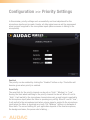
1
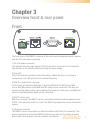
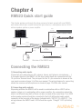
RM523 User Manual www.audac.eu 2 Index Introduction 5 Environment 7 Chapter 1: Safety requirements Caution servicing 9 9 Chapter 2: Pin connections and connectors 11 Chapter 3: Overview front and rear panel 13 Chapter 4: RM523 Quick start guide 15 Chapter 5: User interface & configuration 19 Chapter 6: Additional information 31 Front Rear Connecting the RM523 Configuring the RM523 Ready Login screen Main screen Configuration screen Network settings Wall panel settings Input settings Priority settings Password settings Factory settings IP Basics Technical specifications 13 14 15 16 17 19 20 22 23 24 25 26 28 29 31 33 3 4 Introduction Web Based Input Control Unit The RM523 is a web based input control unit, featuring four stereo line inputs and one balanced microphone input with phantom power, allowing the connection and control of several stereo audio source devices (such as CD-player, Tuner, MP3 player, ... ) and a microphone to one (potentially two) output device(s). Two outputs are provided, one stereo line output, and one differential output with increased voltage level performed with an RJ45 connector, which is especially meant for connecting the LX523 loudspeaker system. The control of the device can be done in two different ways: an integrated website makes it possible to control all the functions from any computer with a web browser without requiring additional software, while the RS232 connection makes it possible to control the RM523 with any device supporting serial communication, such as a computer or even a home automation system. The various input signals can be patched to the output with a two-band tone control, while the microphone channel has the possibility to provide 12V phantom power for powering condenser microphones. Priority settings on the microphone channel make it possible to supress other sources when someone is speaking into the microphone. To make the installation even more complete, an optional DW3018/4018 wall panel can be installed to control the signal routing and volume level from one or multiple fixed locations. 5 6 Environment Do not place the unit in environments which contain high levels of dust, heat, moisture or vibration. Do not use the unit near water or other liquids. Make sure no water or other liquids can be spilled, dripped or splashed on the unit. The unit is developed for indoor use only. Do not use it outdoors. Do not place objects (books, vases, … ) on top of the unit. Place the unit on a stable base or mount it in a stable rack. 7 8 Chapter 1 Safety requirements Always handle the unit with care. Only use a grounded socket outlet and a power cord with grounding plug to plug in the unit. This unit is not a toy. It should not be operated by children. Do not open the unit. (risk for electrical shock) CAUTION - SERVICING This unit contains no user serviceable parts. Refer all servicing to qualified service personnel. Do not perform any servicing unless you are qualified to do so. NOTE T his produc t conforms to the following European S t andards: EN 50081-1: 1992, EN 50082-1: 1992, EN 60065: 1994 9 10 Chapter 2 Pin connections and connectors RS485 + AUDIO RJ45 (RS485, Audio, +24V DC): For connection to Wall Panel controller & Input Units Pin 1 White-Orange Pin 2 Orange Pin 3 White-Green Pin 4 Blue Pin 5 White-Blue Pin 6 Green Pin 7 White-Brown Pin 8 Brown AUDIO WLI+ AUDIO WLI+24V DC RS485 A RS485 B GND AUDIO WMI+ AUDIO WMI- AUDIO LEFT AUDIO LEFT N/C N/C GND GND AUDIO RIGHT AUDIO RIGHT Output (To LX523) RJ45 (Audio): For connection to LX523 Speaker system Pin 1 Pin 2 Pin 3 Pin 4 Pin 5 Pin 6 Pin 7 Pin 8 ATTENTION The twisted pair cabling must always be ‘straight’. In case of self made cabling, it must be wired as described above, to make the system work properly. White-Orange Orange White-Green Blue White-Blue Green White-Brown Brown 11 Line in- or output Microphone input RS232 (serial connection interface): For connection with home automation systems, or other remote control equipment Connection Standard RS232 PIN 2 RM523 TX PIN 3 RM523 RX PIN 5 GND Settings 19200 Baud 8 Bit 1 Stop bit No parity No Handshaking RS232 / TCP/IP The RM523’s RS232 and TCP/IP accept the same commands. The complete command set is available in the RM523 commands user manual which is freely available on www.audac.eu/download. 12 Chapter 3 Overview front & rear panel Front The front panel of the RM523 containes all the control and configuration ports, together with the 24 Volts power connection. 1) 24 Volts power connector: The included 24 volts power supply (PSD242) should be connected to this connector. Pay attention to the polarity when connecting the power supply. 2) Run LED: This LED shows the operation mode of the device. When the device is running in normal mode, this LED will blink at a constant frequency. 3) RS485 + Audio RJ45 connector: To this input, an additional Wall Panel Controller (DW3018 of DW4018) and Wall Line or Wall Microphone input (WMI and WLI units) can be connected. This way, the volume and the signal routing can be adjusted by means of a wall panel and additional local Line and Microphone inputs can be connected. 4) RS232 control port: With this connector, the RM523 can be connected to external control hardware using RS232. This makes it possible to control the RM523 by means of an home automation system. 5) Ethernet connection The RM523 can be connected to an Ethernet network with this RJ45 connector. This makes it possible to control the RM523 functions over ethernet, by simply using any device with a web browser such as computer, smartphone, ... 13 Rear At the rear side of the device are all audio in- and outputs provided. The various available inputs are 4 unbalanced line-level inputs and one balanced microphone input (with phantom power possibility). Those inputs are all performed with an 18-pin Euro-Terminal block connection (together with the line-level audio output). Audio sources such as CD-players, Tuners, MP3 players, ... can be connected to the line-level inputs, while microphones can be connected to the microphone input. When using condenser microphones, the phantom power possibility should be enabled. There are two different kinds of audio outputs provided, both of them carrying the same audio signal with different voltage levels. The audio output performed on the Euro-Terminal connection block is a standard line-level audio output whereby the RM523 can be connected to any audio device with a line-level input such as an amplifier, pre-amplifier, active speaker system, ... The second output is performed with an RJ45 and is a differential audio output with increased voltage level, meant to connect the RM523 unit to the LX523 speaker system. Because of the differential signal and increased voltage level, the maximum cable distance can reach a cable length up to 500 meters over CAT5 cabling and makes the signal insensitive for noise and interferrence caused by external devices. 14 Chapter 4 RM523 Quick start guide This chapter guides you through the setup process of a basic project with one RM523 web based control input, several stereo line input devices, a microphone and an LX523 activive speaker system or power amplifier. stereo line input cd player stereo line input computer 1 2 3 4 5 6 stereo line input mp3 player tuner ......... TCP/IP ok home automation system balanced mic input RS232 UTP cat5 cabling LX523 stereo line output Overview of the RM523 setup Connecting the RM523 1) Connecting audio inputs Connect all your audio sources (CD-players, tuners, mp3 players, microphones, ... ) to the audio inputs of the RM523. All the direct audio inputs are connected with the 18-pin Euro Terminal block. The pin layout for the 18-pin connector is shown at the rear panel overview at page 14 of this user manual. The wiring diagram for connecting stereo line sources and microphones is shown at page 12 of this user manual. 2) Connecting audio outputs Depending whether the RM523 will be used in combination with an LX523 active speaker system or in combination with a power amplifier, the connections should be made in a different way (both of them can also be used at the same time). The LX523 active speaker system should be connected to the RJ45 differential audio output connector at the rear side of the device (indicated with “OUTPUT (To LX523)”). The wiring between the RM523 and LX523 should be regular “Straight” CAT5 (or better) cable. 15 A power amplifier should be connected to the direct line output which is provided on the 18-pin connector. The pin layout for the 18-pin connector is shown at the rear panel overview at page 14 of this user manual. The wiring diagram for connecting a power amplifier is identical to the inputs wiring diagram, as shown on page 12 of this user manual. 3) Connecting the power supply The included power supply should be connected to the 2-pin Euro-Terminal block connector. Watch the polarity when connecting the power supply. 4) Connecting a computer A computer can be connected to the RM523 through true ethernet. If the computer is directly connected to the RM523, a crossed network cable is necessary. If the RM523 is connected to a local LAN network (connected to a router / switch / hub) a straight network cable is necessary. Ask your IT administrator for help. To get access to the user interface, enter the following address in your internet browser address bar: “http://192.168.0.193” (This is the factory default IP address of the RM523, can be changed in the user interface). The default password is “RM523”. Configuring the RM523 1) Changing the IP address You can skip this step when the default IP address “192.168.0.193” is not used by another device in your network, and is OK for you. If you like to change the IP address, go to the “Setup” menu (click the icon in the upper right corner of the main screen) and click “Network Settings”. Now you can change the IP address, and click “OK” to apply the changes and save. Afterwards, your browser will be automatically redirected to the new IP address of the RM523, and the default IP address is not longer valid. 2) Changing the password You can skip this step if the default password “RM523” is OK for you, buy we always recommend to change the password, especially when your RM523 is connected to a public network where external users have access to. If you like to change the password, go to the “Setup” menu and click “Password settings”. Here you can change the password. First, the old password needs to be entered, and subsequently the new password needs to be entered twice (Max 10 characters). Press the “OK” button to save the new password. Now, you always need to log-in with the new password and the default passwords are not longer valid. 16 Ready Your system is now ready for use. Go to the main screen of the RM523 and you are in full control of all the RM523 functions. 17 18 Chapter 5 User interface & configuration To get access to the control and configuration settings, the RM523 should be connected to a computer or en Ethernet LAN network. For more information about network connections and settings, see IP basics in chapter 8. The standard (factory default) IP address of the RM523 is 192.168.0.193, make sure this address is within the IP range of the connected Ethernet LAN network (subnetmask 255.255.255.0). If the default network address is not within range of your LAN network, contact your network specialist. The network address can be changed with the Standard Web Based User Interface but therefore a network connection has to be made first! Any device (PC, Laptop, PDA or even a Smartphone) with a web browser and the Macromedia Flash 8.0 plug-in (or higher) installed, can be used to control the web based user interface. For mobile devices, such as PDA’s, smartphones or even iPhones or iPads, special applications are developed to control the standard functions of the RM523. Open the user interface Start your default web browser and enter in the address bar the IP address of the embedded web server of the RM523. (The factory default IP address is http://192.168.0.193). The loading screen will be displayed while the integrated website of the RM523 is loading. Login screen First the login screen will be displayed. A password should be entered to get access to the web interface. After the correct password is entered, click the “OK” button, and you will be redirected to the main screen of the RM523. (The factory default password is “RM523”) NOTE The passwords can be changed in the Configuration >> Password settings menu 19 Main screen After the correct password is entered, the main screen of the user interface will be loaded as shown below. This displays the selection buttons for all 5 input channels (CH1 to CH4 and WLI-WMI/MIC) accompanied with a mute button, Mixing faders for the WLI and MIC/ WMI Channels, a General volume fader and two band tone control for Treble and Bass equalization. Connection status At the top centre position is the “Connection Status” displayed. To have communication with the RM523, the connection status must be “ONLINE”. Input channel selection The input channel to be routed with the output can be selected by using the selection buttons in the centre position of the main screen. Selection buttons are shown for “No input”, the direct line inputs Channel 1 to Channel 4 (CH1 to CH4), and the microphone input which is mixed with the signals coming from the additional input units as WLI and WMI units. 20 Mute button Below the input channel selection buttons is a big MUTE button provided, whereby the output signal can be completely supressed. When the signal is muted this button will become Red. The output can be unmuted after clicking this button again. Volume Control The output volume can be set by moving the master fader up and down. The master fader is indicated with “Output” located on the right side next to the input selection buttons. At the top and bottom side is a button with an arrow displayed whereby the volume can be raised and lowered in steps of 1 dB. Mixing faders for WLI and MIC/WMI At the left side of the main screen are two mixing faders displayed. With these faders, the signals coming from the additional wall panel inputs can be mixed with each other. The mixing with WLI and MIC/WMI channels is 50% and the level can be adjusted with both faders between 0 dB and -∞ dB. This can be easily done by sliding the faders up and down or by pressing the arrowed buttons on top and bottom of the faders. This way the level can be raised and lowered in steps of 1 dB. Two band tone control At the right side of the main screen are two faders displayed which are meant to adjust the sound settings through two-band tone control. The leftmost fader indicated with “Bass” offers the possibility to adjust the level of the low frequencies, while the rightmost fader indicated with “Treble” offers the possibility to adjust the level of the high frequencies. The sound level level for both low and high tones can amplified or attenuated between +14 dB and -14 dB. Configuration menu In the top right corner is a “Setup” button displayed. After clicking this button, you will be redirected to the general configuration menu of the RM523. Save Press the “Save” button in the top right corner when any changes are made to the settings on the main screen. Otherwise all settings will be set to default after reloading the web-based interface. 21 Configuration screen The settings control panel comes up after clicking the “Setup” button in the top right corner of the main screen. In this window, all settings for the RM523 can be made. Such as network settings, setting the address for the connected wallpanel (optional), changing the gain for the input channels, enabling phantom power to the microphone channel, enabling priority settings for the microphone channels, changing the password, ... Different icons are shown for “Network Settings”, “Wallpanel Settings”, “Input Settings”, “WMI/Mic Priority”, “Password Settings and restore to “Factory Settings”. Click the particular button if you want to make any changes to those settings. Back Click the “Back” button to return back to the main screen. 22 Configuration >> Network Settings In this window, the network settings of the RM523 can be adjusted. The IP address is default set to 192.168.0.193 and the subnetmask is default set to 255.255.255.0. The settings can be changed by adjusting the parameters in the shown fields. To confirm the settings, press the OK button. The changed settings will take immediately effect. For more information about network connections and settings, see IP basics in Chapter 8. 23 Configuration >> Wall panel Settings In this window, the wall panel address settings for the DW3018/DW4018 wall panels can be made. The address is always set correct for new delivered wall panels. When the connected wallpanel is used before in another application, it can be configured to another address. To avoid problems in all circumstances, it is recommended to always run through the RM523 wall panel address configuration procedure. This is very simple. Set Address Just connect the DW3018/DW4018 wall panel to the “RS485 + AUDIO” RJ45 input on the RM523. After this is done, the “Set Address” button should be pressed in the “Wall panel Settings” menu. The message “Push the upper button on the wall panel to confirm the address” will appear and the LED’s on the DW3018/DW4018 wall panel will start blinking. After the upper button on the wall panel is pressed, the correct address will be assigned. and the message will disappear. Now the wall panel is ready for operation. Back Click the “Back” button to return back to the settings screen. 24 Configuration >> Input Settings In this window, input settings such as input gain adjustment and phantom power enabling can be made. Input gain On the left side are all input channels shown, together with a dropdown box. Hereby the input gain for every channel can be adjusted. The input gain for every channel is default set to 0 dB. It can be set adjusted between -4 dB and +10 dB, in steps of 2 dB. This can simply be done by clicking the dropdown box and selecting the desired gain adjustment factor. After the desired value is selected, the changes are immediately effective. Phantom power On the right side is a button shown whereby the phantom power for the microphone channel can be enabled. This can simply be done by clicking this button. When the phantom power is enabled, this button will become green and 15 Volts phantom power will be delivered to the microphone input. (Only direct mic input and not WMI) Back Click the “Back” button to return back to the settings screen. 25 Configuration >> Priority Settings In this window, priority settings such as sensitivity and level adjustment for the microphone inputs can be made. Hereby, all other signal sources will be suppressed when a signal is applied to the microphone inputs (when someone is talking in the microphone). Enabled The priority can be enabled by clicking the “Enabled” button on top. This button will become green when priority is enabled. Sensitivity The sensitivity for the priority channel can be put on “High”, “Medium” or “Low”. Hereby, the level when switching to the priority channel can be set. When it’s set to “High”, it will switch to the microphone channel when only a small signal is applied to the microphone input (when the talker is speaking very softly). When it’s set to “Low”, it will switch to the microphone input when a large signal is applied to the microphone input (when the talker is speaking very loud). The “Medium” setting is in between of those both. The correct setting for your application depents of the used microphone, the background noise, the person who’s talking, ... 26 Output Level The sound level of the priority signal can be adjusted with this dropdown list. This way, the volume can change when a priority announcement is made. For example, to make sure a priority message always heard at the maximum volume, ... The output level for priority messages is default set to 0 dB and can be adjusted between 0 dB and -∞ dB, in steps of 1 dB. WMI/MIC Level The level of the priority input can be set by means of this dropdown box. The correct level depends of the used microphone, and should be set correctly so the microphone signal is not overdriven. Back Click the “Back” button to return back to the settings screen. 27 Configuration >> Password Settings In this window the password for the RM523 can be changed. To change the password, enter the old password in the provided field and enter the new password twice in the provided fields. After this is all completed, push the “OK button. When the old password is correct, and the new password filled in both fields match, the old password will be changed into the new password. 28 The factory default password is “RM523”. Configuration >> Factory Settings BE CAREFULL to press this button. It really will recall the ORIGINAL factory settings !!! It does not recall the previously saved settings, but it recalls the original factory setting and the previously made settings will be lost. Click the “OK” button to reset the settings to factory default. 29 30 Chapter 6 Additional information IP Basics Many AUDAC products are controllable by Ethernet. The Ethernet connection which is used on the AUDAC products is TCP/IP based like 99% of the computer networks. There are some basics which you need to know to successfully make a TCP/IP Ethernet connection. The data in TCP/IP networks is always send in packages, all these packages must be delivered at an unique address, just like the mailman delivers mail at your home mailbox. In TCP/IP networks, this address is called the “IP address”. The IP address is always a number in the following format “192.168.000.001”. As you can see, this address consists of 4 separate numbers ranging from “000” to “255”. In simple terms, only the latest number of an IP address can be different within a network, so there is a maximum of 256 unique addresses within a network, ranging from “xxx.xxx.xxx.000” to “xxx.xxx.xxx.255”. The first three numbers must be the same to make communication between several devices possible, else the devices can not communicate with each other. Example: Device 1: IP address: 192.168.000.001 Device 2: IP address: 192.168.000.002 Device 3: IP address: 192.168.001.003 In this example, Device 1 can communicate with Device 2, but not with Device 3, because the first three numbers must be the same. These first three parts are called the “IP range”, so the devices must be in the same “IP range” to communicate with each other. 31 The “IP range” of home and office networks are defined by the network administrator, this means that the IP range of your home or office network can be different from another network. AUDAC products have the following IP address as default: “192.168.0.xxx”, this means the standard IP range of AUDAC products is “192.168.000.xxx”. If your network is using a different IP range, the AUDAC products will not be accessible from your network. You can change the IP address of the AUDAC products to make them work properly in your network. This can be done in the settings menu, and is described extensively in the “Settings” chapter of this user manual. Of course, to make changes to the settings menu of the AUDAC products, you must have access to the user interface on the products webpage. This can be done by temporarily giving your computer an IP address within the IP range of the AUDAC product, for example “192.168.0.200”. After the IP address of your computer is within the IP range of the product, the user interface is accessible and the IP address of the product can be changed to an IP address within the IP range of your network. If the IP address of the product is within the IP range of your network, you can change the IP address of your computer again to it’s former IP address and the product should work properly in your home or office network. Ask your network administrator for help if you are not familiar with networks. Summary - All devices must have an unique IP address - All devices must be within the same IP range 32 Technical specifications Peripheral Inputs 4 x Line input 1 x Microphone Input 1 x Diffential audio input (WLI+WMI) Outputs Connectors Line & Mic audio input Power RS-232 Ethernet Differential RS485 + audio input Differential audio output 1 x Line output 1 x Differential audio output (LX523 18-pin Euro Terminal Block 2-pin Euro Terminal Block DB-9 RJ45 RJ45 RJ45 Specifications Sensitivity Line input Sensitivity Microphone input THD+N Crosstalk -10 dB / +4 dB -45 dB / -20 dB < 0.03 dB < -75 dB Control Digital Web based RS-232 RS-485 (RJ45 input) Ethernet Other Power supply 24V DC PSD242 switching power supply included 100 ~ 240V AC / 47~63 Hz Weight Dimensions Shipping weight & volume 0.415 Kg 110 x 44 x 160 mm 1.20 Kg - 0.0078 Cbm 33