1
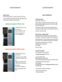
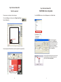
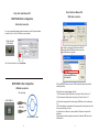
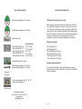
Vinyl Cutter Accessories
Blades 45 degrees package of 1 or 5 blades
Blades 60 degrees package of 1 or 5 blades
Blade holder original
Cutter strip length
Cutter strip Model 360C (12”)
Cutter strip Model 450C (15”)
Cutter strip Model 720C (24”)
Cutter strip Model 800C (30”)
Cutter strip Model 1360C (48”)
14-1/4” or 360mm
17-1/2” or 445mm
28” or 711mm
31.5” or 800mm
53-1/4 or 1352mm
Vinyl Cutter User Manual V5.0
Thank you for choosing our vinyl cutter:
Before using your vinyl cutter, we propose to you that you read this manual
and to view the DVD supplied with your cutter. We will show you how to use
your cutter and how to maintain your cutter in good running condition. When
you have trouble in using cutting plotter, please turn off the machine's power,
then look for the solution in this manual. If you contact the machine dealer he
will help you to resolve problems. A free assistance on the Web site
www.signmax.us (forum) or by email [email protected] is available.
Which is your model?
360C cutting plotter (12")
450C cutting plotter (15”)
720C cutting plotter (24") c/w stand
800C cutting plotter (30") c/w stand
1120C cutting plotter (42") c/w stand
1360C cutting plotter (48") c/w stand
Special Blade holder with 4 nooses
Remarks of the manufacturer:
Blades 45 degrees package of 1 or 3 blades
Blades 60 degrees package of 1 or 3 blades
Engraving kit
Pouncing kit
If your cutter becomes defective either needs maintenance or parts your
dealer will help you to find the suited solution . But we have no responsibility
to pay for the damage.
Pouncing strip replacement for 12”, 15”, 24”, 30”
Pouncing strip replacement 48”
Place order from:
Entreprises Sign Max Inc.
Tel.: 514-644-3177 Fax: 514-644-3173
www.signmax.us
[email protected]
20
2009-05-19
1
Vinyl Cutter User Manual V5.0
Base assembly ...
If you use vinyl roll, please before to cut unwind in advance the quantity of
material necessary for the cutting.
Place the pinch rolls about 1 inch inside on each side of vinyl, also lower the
intermediate pinch rolls.
To verify manually your vinyl alignment, place the cutter "OFF Line" (Red
Led) and use the top and bottom arrows to feed in and out vinyl from the
cutter.
OR
To verify your vinyl alignment using the cutting control panel from
WinPCSIGN software, place the cutter "ON Line" (Green Led) click the feed
button, the cutter will unwind the necessary quantity of vinyl material for your
cut then will return in the point of departure the origin point (0,0).
A) 4 plastic dowels.
B) 4 plastic caps.
C) 6 cover nuts.
D) 6 nuts 1 1/4” length.
E) 8 screws 1 ½” length.
F) 4 screws 5/8” length.
G) 8 screws 3/8” length.
Arrange parts as show in
the picture.
Before to cut:
1)Cutter in On Line (Green Led)
2)Click the alignment button to
check your alignment.
Use screws (E), fix the bases to the
sides bars.
Place 2 dowels in sides, use screw
shown in F and fix to the horizontal
bar.
Manual check of the
alignment:
Remember always unwind manually the
necessary quantity of vinyl before
proceeding to the alignement test or
cutting.
2
Cutter “OffLine” Red led.
Use down arrow to feed out
vinyl material.
Use top arrow to feed in vinyl
material.
Use C inside to fix the rolls bracket
Use the 8 screws shown in G to fix
the top braces.
Use a square or a
paper fix brackets at 90
degrees with the side
bars.
19
Vinyl Cutter User Manual V5.0
Base assembly ...
CONTENTS
(1) Cutting plotter models
(2) Vinyl alignment
(3) Contents
(4) Notice when using your cutting plotter
(5) Cutting plotter packaged accessories
(6) Main parts descriptions
(7-8) How to install plotter
(9-10) WinPCSIGN serial cutter configuration
(11) WinPCSIGN USB cutter configuration
(12) Test the equipment and configuration
(13) Keyboard panel operating detail
(14) On Line, Off Line mode
(15) Cutting blade
(16) Plotting pen
(17) Warranty
(18) Base overview
(19) Base assembly
(20) Accessories
18
3
Vinyl Cutter User Manual V5.0
Notice
Vinyl Cutter User Manual V5.0
Equipment Limited Warranty
(5) Don't remove or plug any wire when cutting plotter or computer is power
on.
Return Warranty Registration Form to activate your warranty.
The following is a general warranty statement for all equipment. To receive
the complete warranty statement specific for your product, please register
your product online and we will forward you the product specific warranty.
All products are of the highest quality craftsmanship and are warranted
against defects in materials, circuitry and/or workmanship. All equipment
warranties for a period of one year and include parts and labor. The warranty
begins from the date of purchase and REQUIRES that the purchaser send a
completed Warranty Registration Form to dealer or register online within 30
days of purchase.
Under no circumstance will be liable for direct, indirect special, incidental, or
consequential damages resulting from any defect in hardware or
documentation, even if advised of the possibility of such damages. Though
we has tested the equipment, the purchaser assumes all risks regarding its
quality and performance.
(6) Cutting plotter's shell must be connected to the ground with a metal wire.
Special Notice Regarding Vinyl Cutter Equipment
(1) Sign Max cutting plotter’s power supply is 90V-230V, when your power
supply does not fit the requirement, please add the right power cable. This
cutter arrives with a cable of 110V and ready to operate under 110V. If you
wish 220V use a cable 220V and change the internal cooling fan of the cutter
for one operate under 220V.
(2) Don't touch the plotter’s track when it is running. If the plotter is damaged
or works wrongly for this reason, we will repair your plotter but not free.
(3) Prevent the small objects falling on or into the plotter.
(4) Please turn off the power if you don't use plotter for a long time.
Blade, blade holder, cutter strip, pinch rolls, head carriage, media have been
tested to ensure consistent quality output will not be covered by warranty.
This warranty does not cover shipping damage or defects due to abuse or
mishandling. In addition, the warranty is void if the product has been opened
or serviced in any way by someone other than a service technician.
Contact our technical service to obtain necessary information to open and
verify your cutter. During the shipping or working the head of the cutter can
take out rails, how to replace the cutter head adequately in the rails. To help
user various films are available.
4
17
Vinyl Cutter User Manual V5.0
Vinyl Cutter User Manual V5.0
Plotting pen:
Lock nut
Pen holder shell
Pen tip
You can use standard ball pen refill as plotting pen; keep the ball pen tip out
of the holder between 4mm and 5mm. Using method is similar as blade's
process; please try it yourself according to the blade's changing method.
Set the knife holder or pen holder on holder's seat:
Turn off the plotter power.
Set the holder on holder's seat, turn the screw of seat of holder.
Turn on the power, the carriage will move to right side; you can press "TEST"
key to check your cutter configuration.
Load media /Load paper.
When you open the box, check the contents with the check list inside,
make sure that nothing is missing, every box must content:
Name
Cutting plotter
User manual
Sign software
Power cable 110V
Serial cable Rs232
USB cable
Fuse
Ball pen
Ball pen holder
Blade
Blade holder
Plotter ruler
Plotter cover sheet
Stand
Quantity
1 unit
1 book
WinPCSIGN Basic or Pro version
1 pcs
1 pcs
1 pcs
1 pcs
1 pcs
1 pcs
3pcs / 1
1 pcs
1 pcs
1 pcs
1pcs (only for 720/800/1360)
Load media /Load paper:
When you move the roller, you must lift the handle first; the right roller will not
move, usually.
Lift the handle, the roller will lift 1-2mm, then you can load your media.
Laying down the handle, you can press "UP" key (S+) or "DOWN" key (S-)
continuously, the paper will roll to front or back; please confirm the paper
must move straightly during the distance that you want to cut.
Adjust the speed and pressure, and then you can output the data to the
plotter.
16
5
Vinyl Cutter User Manual V5.0
Vinyl Cutter User Manual V5.0
Cutting Blade and Plotting Pen
Main parts descriptions
Cutting Blade Holder:
Front side / Left and Right sides
1
2
3
4
Lock Screw
Blade Holder Shell
Adjustable nose.
Blade tip. (Blade extension)
The distance between the blade end and the media is maximum 1/8” or 3mm.
Adjust the blade holder in the cutter carriage to obtain a the right clearance
and tighten the tool securing screw until the blade holder is secured in place.
1) Protection cover
2) Carriage
3) Roller
4) LCD display
5) Keypad panel
6) LED lamp
7) Right shell
8) Machine’s foot
9) Blade holder
10) Seat of blade holder
11) Left shell
12) Pinch roll hand level
13) AC power port
14) Safe fuse
15) Power’s switch
16) RS232 port (Serial port)
17) USB port (USB cable)
6
On the working state, the blade can rotate in holder very smoothly. To change
the blade, unscrew the nose of the blade holder, pull out the old blade and
push the new blade in the blade holder until it hit the bottom then screw the
nose. Let exceed the end of blade about 0,25 mm and perform a cutting test.
The amount of blade extension is optimal when the blade leaves a faint mark
on the base paper.
Remark:
Do not touch the tip of the blade with your fingers. Doing so may result in
injury. Depending on the material in use, it may be necessary to adjust the tip
of the blade. The amount of cutter blade extension can be adjusted by
rotating the noose cap. Take care to ensure that the amount of blade
extension does not exceed the thickness of the material plus the half
thickness of the base paper.
15
Vinyl Cutter User Manual V5.0
Reset the plotter:
When the cutter works badly or if you wish to stop quickly the cutter, press
only once the “Reset” key. All data in the cutter memory will be erased and the
carriage will return to the right side near the cutter wall.
Summary of the operation in “ON Line” mode
1) Press the button “ON Line” to see
the button light green.
2) You can send data to the cutter
3) You can change speed using
4) You can change pressure
Vinyl Cutter User Manual V5.0
How to install machine
(1) Place the machine:
Place the plotter in a clean room.
Place the machine on a horizontal table, adjust plotter four foots, to keep
plotter very horizontally. Make enough space not only to the front of plotter
but also to the back of plotter.
No vibration when plotter is running. Don't touch the plotter with magnet.
We suggest you connect the machine's metals shell with the ground using a
metal wire, to avoid static electricity.
(2) First power on, examining plotter:
Set the power cable to machine power port, connect the power cable to
AC110V power. Turn the power ON, the green LED on the cutter keyboard
will light when power is on. Later, the carriage must move to right side itself,
and return a little. This is the initialization of cutting plotter. The message of
speed and pressure will be showed on the LCD monitor.
Followed are the machine parameters:
Speed: 600mm/s
Pressure: 150 grams
Summary of the operation in “OFF Line” mode
1) Press the button “ON Line to see
the button light red.
2) You can press continuously DOWN
or UP arrow to move vinyl in or out the
cutter.
3) You can press continuously LEFT
or RIGHT arrow to move the carriage
head anywhere.
4) If you press the “OK” button you
define a new origin where the head is
placed.
14
(3) Connect to computer:
There are two ways to link a cutter to a computer:
First method: Serial connection (RS232 cable)
A) Install the WinPCSIGN software
B) Install the RocKey2 key on a free USB port.
C) Use the serial cable supplied with your cutter, connect one end to the computer
serial port and the other end to the cutter serial port.
Power ON the cutter.
Run the WinPCSIGN software, from the setting menu, plotter codes configure the
WinPCSIGN software :
- Your cutter model normally SM cutter or RedSail cutter
- Select Com1 if free or select Com2 port
- Click the Accept/Save button.
7
Vinyl Cutter User Manual V5.0
Vinyl Cutter User Manual V5.0
Keyboard panel operating detail
Second method: USB connection
A) Install the WinPCSIGN software
B) Install the RocKey2 key on a free USB port.
C) Use the USB cable supplied with your cutter, connect one end to the computer
USB port and the other end to the cutter USB port.
Turn the cutter power ON.
The USB driver is already installed Windows detects a new peripheral and complete
the installation of the USB driver.
When you turn on the plotter's power, after for a moment, the carriage will
move to right side itself and the green LED on keyboard will light. The LCD
monitor will show the data for speed and pressure. This process is an
initialization of the plotter. On this keyboard, four arrow keys will be used as
speed's key and pressure's key. Those arrow keys have different functions
in different mode. Plotter has two working mode: On Line, Off Line
Run the WinPCSIGN software, from the setting menu, plotter codes configure the
WinPCSIGN software:
- Your cutter model normally SM cutter or RedSail cutter
- Select USB port
- Select USB plotter, the USB driver “USB <---> Serial”
- Click the Ok button
- Click the Accept/Save button.
Online mode:
Detailed configuration process:
Turn on the computer; turn on the plotter, waiting a moment for machine
Initialization.
If the red LED on keyboard is light, please press the "ONLINE" key one time.
When the green LED on keyboard is light, you can output the data from
computer to your cutting plotter.
Receive the data: when you turn on the plotter's power, the green LED on
keyboard will light after a while, we call this mode "ONLINE". On "ONLINE"
mode, the plotter can receive data from computer. (Notice: if you want
to output the data to plotter later, please must return to this mode).
Change speed: on "ONLINE" mode, if you want plotter’s work quickly, you
can press "S+" key; if you want slowly you can press "S-" key. (Remark: if
the work you want to cut is big, you can select quickly or slowly; if the work
you want to cut is small, you must select slowly. The smaller the less slowly,
because slower means more accuracy).
Change pressure: on "ONLINE" mode, if you want cutting pressure is
heavier, you can press "P+" key; if you want slighter you can press "P-" key.
(Remark: If you cut thick material you should use a higher pressure, on the
other hand if you cut thin material you should decrease pressure. A new
blade needs much less pressure than an used blade. A high pressure causes
a premature wear of the blade and can break the end of the blade.
Offline mode:
If the red LED on keyboard lights, we called "OFFLINE" mode. On this mode,
you can press any arrow key continuously to move the carriage or paper to
everywhere you want it go. Later press "OK" key, a new origin will be defined.
(The origin point defined on the cutter corresponds to the origin point of the
working page of the computer.)
Plotter cutting test:
On "OFFLINE" mode, you can press "TEST" key and the plotter will cut a
small rectangle itself. According to this, you can adjust the speed or pressure
to find out the best cutting parameters.
8
13
Vinyl Cutter User Manual V5.0
Vinyl Cutter User Manual V5.0
WinPCSIGN Cutter configuration
To test the equipment:
Draw a square or a rectangle on the working page.
Run the WinPCSIGN software and from the Settings menu, click on Plotter Codes
Click on the Cutting icon, this will open the Cutting Control Panel
Press the Start button.
8
Origin Point (0,0)
Then from the setup plotter
window click on Add/Remove.
Locate your plotter model, select
it and click on the arrow to place
the plotter in the visualization
windows to the right. Finally click
OK and Accept/Save
Draw rectangle near left hand bottom corner this represent the origin point (0,0)
Your cutter
24,000
Cond1
Cond2
Your Cutter
Locate your plotter model, select it and click on the arrow
to place the plotter in the visualization windows to the
right. Finally click OK and Accept/Save
Origin Point (0,0)
12
9
Vinyl Cutter User Manual V5.0
Vinyl Cutter User Manual V5.0
USB cable connection.
WinPCSIGN Cutter configuration
Serial cable connection.
Your cutter model
If you use a serial cable between cutter and computer, use the Com port available,
normally is Com1 or Com2. (9 Pin Male on your computer)
Cutter serial port
(9 Pin female)
Your Cutter
If your cutter is configured to USB, Insert the Mini CDRom and click Select USB Plotter button to select the
proper USB cutter driver installed.
12
After Com port selection, click on Accept/Save
17
if your cutter USB driver is
not in the list?
WinPCSIGN Cutter configuration
Click the REFRESH button to close the USB port selection window and click the
Accept/Save button.
USB cable connection.
If the printer driver does not appear in the list.
1) Close the window “Select USB plotter” by clicking the “Cancel” button or “X”
2) Close the window “Setup plotters” by clicking the “Cancel” button or “X”
See next page ...
Cutter USB port
USB cable
USB cable driver Cd-Rom
10
a) Connect the computer and the cutter using the USB cable, turn the cutter power
On.
b) If Windows detects a new peripheral it will generally ask for the printer driver; this
driver is provided with your cutter.
c) Install the driver. If the driver is already installed, Windows will complete the
installation.
d) Begin again the cutter configuration procedure, this time the USB driver will be
visible select it.
11