1
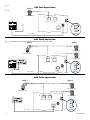
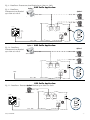
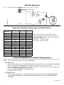
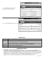
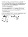
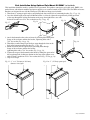
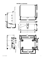
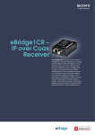
Rev. 081214 Installation Guide PLUS eBridge200WPM - Outdoor Managed Two Port Transceiver I.T.E. 43KC Overview: These long range PoE Ethernet transceiver/media converters transmit data and power over Coax or CAT5 cable over distances that are 3 to 5 times greater than standard Ethernet. Upgrading existing Coax analog camera infrastructure to IP cameras is greatly simplified as well. Two PoE cameras/devices can be attached and supports PoE, PoE+ or a single Hi-PoE (60W) device. The eBridge200WPM/WPMH offers built-in IP management which allows for remote camera reset, monitoring and reporting via various IP protocols. No need to install remote AC mains power since these devices are simply powered from the low voltage PoE midspan/endspan equipment, such as Altronix NetWay midspans or eBridge100SPR. Note: Ethernet maximum distance (see Maximum Length of Coax Type vs. Camera Power/PoE Class, pg. 4). Features: Environmental: Input: • UL Listed LPS PoE Power Supply. See input options table below. Power Output: • 2 ports PoE/PoE+ (30W) per port or 1 port Hi-PoE (60W). • Total output power: 60W. Ethernet: • Operating Temperature: 60W over CAT5 -40ºF to 167ºF (-40ºC to +75ºC). 60W over Coax -40ºF to 149ºF (-40ºC to +65ºC). 45W over Coax -40ºF to 167ºF (-40ºC to +75ºC). • Storage Temperature: -- 40ºF to 167ºF (--- 40ºC to +75ºC). • Humidity: 20 to 85%, non-condensing. Applications: • Link Distance: 500m max. (with Pace or eBridge100 series PoE receivers to eBridge200WPM) or 100m (with standard midspan or endspan to eBridge200WPM). • Connectivity: RJ45, auto-crossover. • Wire type: 4-pair Cat-5 or better structured cable. • Device Distance: 100m max. (eBridge200WPM to camera/device). •Speed: 100BaseT, full duplex, auto negotiation. • Long range outdoor CAT5 or Coax PoE/PoE+/Hi-PoE. • Retrofit digital IP cameras in an analog CCTV installation (up to two (2) IP cameras expansion per analog camera). • Works with Megapixel, HD720, HD1080 and VGA (SD) cameras (see note, pg. 2). • Upgrade deployed CCTV Coax to a digital network in Retail, Hospitality, Arenas, Casinos, Airports, Schools, Hospitals, Transportation, etc. Coax: Mechanical: LED Indicators: Models: • NEMA 4X, IP66 Rated enclosure for outdoor use. • Dimensions (H x W x D approx.): 9.5” x 7.32” x 4.92” (241.3mm x 185.9mm x 125mm). • Link Distance: 300m max. • Connectivity: BNC, RG-59/U or similar. • Speed: 100BaseT, full duplex, auto negotiation. eBridge200WPM: Outdoor Managed Two Port Transceiver. eBridge200WPMH: Outdoor Managed Two Port Transceiver, enclosure with three (3) 5/8” wiring inlets, includes NEMA rated glands. • Speed and Activity of Output ports. • PoE ON the Spare Pair of CAT5 PoE ON the Data Pair of CAT5. Input Power Options and Switch Setting: Receiver Midspan or Endspan Input Power 30W Pace1PRM, 4PRM, 8PRM or 16PRM 30W Pace1PRD* eBridge100SPR** eBridge100RM, 400RM 800RM or 1600RM NetWay1D 60W 60W 30W 60W CAT5 Wiring Configuration Switch Setting 2 pair Provided over 2 pair/ 2 pair on CAT5e Provided over 4 pair on CAT5e ------------Provided over 4 pair on CAT5e 30W CAT or 60W COAX Link Distance 100m 30W CAT or 60W COAX 500m 60W CAT 30W CAT or 60W COAX 30W CAT or 60W COAX 60W CAT 500m 300m 300m 100m *When used with NetWay1D. **Use with UL Listed Class 2 or limited power source (such as NetWay1D). eBridge200WPM/WPMH -1- Installation Instructions: SW3 Wiring methods shall be in accordance with the National Electrical Code/NFPA 70/ANSI, and with all local codes and authorities having jurisdiction. Wiring should be UL Listed and/or Recognized wire suitable for the application. 1. Remove circuit board from enclosure prior to drilling eBridge200WPM (do not discard hardware). Note: Take care to assure that hardware will not interfere with components of the circuit board. 2. eBridge200WPM: Mark and drill desired inlets on the enclosure to facilitate wiring (Fig. 3, pg. 2). Maximum UL Listed NEMA type 4X rated fittings to be used is 1/2”, follow manufacturers specifications for the appropriate size opening. Note: Inlets for conduit fittings should only be made on the bottom of the enclosure. UL Listed NEMA type 4X rated conduit connector/hubs shall be used for the appropriate size inlets. eBridge200WPMH are pre-drilled with three (3) inlet holes for wiring. Skip step 3 if you have one of the aforementioned models. 3. Clean out the inside of enclosure before remounting circuit board. 4. Mounting NEMA4/4X rated enclosure: Wall mount: Mount unit in desired location. Mark and drill holes to line up with the top and bottom holes of the enclosure flange. Secure enclosure with appropriate fasteners (e. g. screws and anchors; bolts and locking nuts, etc.) which are compatible with mounting surface and of sufficient length/construction to ensure a secure mount (Figs. 15a and 15b, pg. 9). Pole Mount: refer to detailed instructions on page 10. Note: All inlets for conduit fittings should be on the bottom of the enclosure. 5. Mount circuit board in enclosure with hardware. 6. To facilitate wire entry utilize weather tight NEMA rated connectors (supplied), bushings, and cable. 7. Connect Coax from eBridge1SPR/100SPR (60W), eBridge100RM, eBridge400RM, eBridge800RM or Fig. 1 eBridge1600RM (60W) receiver to connector marked [COAX INPUT] (Fig. 5, pg. 3). Connect Cat5 from Pace1PRD (60W), Pace1PRM, Pace4PRM, Pace8PRM Pace16PRM (30W) 60W CAT receiver, NetWay1D or Midspan or Endspan (30W) connector marked [CAT INPUT] (Fig. 5, pg. 4) 8. Select input power SW3 on switch marked [60W CAT, 30W CAT or 60W COAX] (refer to Input Power Options and Switch Settings on pg. 1, Fig. 1, pg. 2). 9. Connect structured cable from one (1) 60W camera/device to RJ45 jack marked [Port 1] or 30W CAT connect two (2) individual structured cables from two (2) 30W cameras/devices to RJ45 or 60W COAX jacks marked [Port 1], [Port 2] (Fig. 5, pg. 3). Note: The eBridge is designed to accommodate Megapixel, HD720, HD1080 and VGA (SD) cameras. It is important to note that some high resolution and high frame rate cameras may demand faster headend processing ability, such as a PC graphics card to present a quality image. If the headend processing equipment is insufficient in speed, the image may show pixelation and latency. It is advisable to pretest system if unsure. Alternatively, frame rate and resolution may be reduced to accommodate system equipment. Fig. 2 SW1 1. Power the unit down by removing coax or Cat5e wire from input. 2. Depress and hold down Reset button (Fig. 2) while reconnecting coax or Cat5e wire to input. 3. The Heartbeat LED to the left of the Reset button (Fig. 2) will flash twice indicating unit is reset to factory default. LED1 Reset Factory Settings: Fig. 3 - Bottom of enclosure 1.125” 28.575mm 0.875” 22.22mm Suggested area for Inlets 1.125” 28.575mm 2.4375” 61.91mm 1.25” 31.75mm - 2 - 4.25” 107.95mm eBridge200WPM/WPMH Technical Specifications: Parameter Connections Input power requirements Description BNC for Coax link. RJ45 for ethernet link. UL Listed LPS PoE Power Supply. See input options table pg. 1. Speed and Activity of Output ports. PoE ON the Spare Pair of CAT5. PoE ON the Data Pair of CAT5. Operating Ambient Temperature: UL60950-1 60W over CAT5 -40ºF to 167ºF (-40ºC to +75ºC). 60W over Coax -40ºF to 149ºF (-40ºC to +65ºC). Environmental 45W over Coax -40ºF to 167ºF (-40ºC to +75ºC). Conditions Relative humidity: 20 to 85%, non-condensing. Storage Temperature: -- 40º to 167ºF (--- 40º to +75ºC). Operating Altitude: --- 1000 to 6,561.679 ft. (--- 304.8 to 2000m). Regulatory -------Compliance Weights Product: 3.7 lbs. (1.68 kg), Shipping: 5 lbs. (2.27 kg) (approx.) Indicators 60W Coax Applications: Fig. 4 Option 1 Option 2 CAT-5e - 100m CAT-5e - 100m 30W Camera/Device 60W Camera/Device CAT-5e - 100m PORT 1 PORT 2 SPEED ACTIVITY NetWay1D eBridge100SPR SPR PoE OUT eBridge100SPR - Receiver 30W Camera/Device 60W CAT SW3 SPEED ACTIVITY IN DATA PoE SPR PoE DATA PoE Aux. + --- 30W CAT or 60W COAX 1 SPEED PoE ON 60W CAT ACTIVITY Provides 56VDC Input: 51-56VDC Class 2 or LPS power supply Blue LED Coax link status (SLOC) RJ45 LEDs Yellow - Speed, Green - Activity Green LED Power and PoE DC Power Input Coax Power LED www.altronix.com SLOC Link LED 10/100 Base-T SW3 COAX INPUT Z1409 I.T.E. 43KC --- + CAT INPUT 30W CAT or 60W COAX Coax - 300m Option 1 30W Coax Applications: Option 2 CAT-5e - 100m CAT-5e - 100m 30W Camera/Device 15W Camera/Device CAT-5e - 100m PORT 1 PORT 2 SPEED ACTIVITY 60W CAT eBridge100RM DATA PoE SPR PoE DATA PoE 30W CAT or 60W COAX 1 SPEED EoC Receiver passes PoE/PoE+ ACTIVITY Midspan or Endspan RJ45 LEDs Yellow - Speed Green - Activity Yellow LED Power and PoE COAX INPUT Z1409 I.T.E. 43KC www.altronix.com RJ45 OUT PoE LED PoE Input PoE LED 60W CAT SW3 SPR PoE eBridge100RM Coax 15W Camera/Device SW3 SPEED ACTIVITY CAT INPUT Coax - 300m eBridge200WPM/WPMH 30W CAT or 60W COAX -3- Fig. 5 Option 1 15W Coax Applications: Fig. 6 CAT-5e - 100m 15W Camera/Device PORT 1 PORT 2 SPEED ACTIVITY 60W CAT SW3 SPEED ACTIVITY eBridge100RM SPR PoE DATA PoE SPR PoE DATA PoE 30W CAT or 60W COAX 1 SPEED eBridge100RM EoC Receiver passes PoE/PoE+ SW3 COAX INPUT Z1409 I.T.E. 43KC Coax 60W CAT ACTIVITY Midspan or Endspan RJ45 LEDs Yellow - Speed Green - Activity Yellow LED Power and PoE www.altronix.com RJ45 OUT PoE LED PoE Input PoE LED CAT INPUT 30W CAT or 60W COAX Coax - 300m 60W Cat5e Application: Fig. 7 - Data/Power Transmission from Headend up to 500m over Cat5e Option 1 Option 2 Cat5e - 100m Cat5e - 100m PoE+ Camera/Device 60W Camera/Device Cat5e - 100m PORT 1 OUT IN Pace1PRD - Receiver SPEED ACTIVITY PoE+ Camera/Device 60W CAT Aux. + --- SPR PoE PoE ON IP-UTP Receiver Passes PoE/PoE+ PORT 2 SPEED ACTIVITY SW3 NetWay1D Pace1PRD DATA PoE SPR PoE DATA PoE ACTIVITY SW3 SPEED 60W CAT 30W CAT or 60W COAX 1 RJ45 LEDs Yellow - Activity Green - Speed Green LED Power and PoE www.altronix.com Z1409 I.T.E. 43KC UTP Link RJ45 Link Output PoE LED PoE Input Input PoE LED COAX INPUT 30W CAT or 60W COAX CAT INPUT Cat5e - 500m 60W Cat5e Application: Option 1 Option 2 Cat5e - 100m Cat5e - 100m PoE+ Camera/Device 60W Camera/Device Cat5e - 100m PORT 1 SPEED ACTIVITY 60W CAT PoE+ Camera/Device SW3 NetWay1D PORT 2 SPEED ACTIVITY IN Aux. + --- SPR PoE PoE ON DATA PoE SPR PoE DATA PoE 30W CAT or 60W COAX 1 SPEED COAX INPUT CAT INPUT Cat5e - 100m - 4 - 60W CAT ACTIVITY SW3 OUT 30W CAT or 60W COAX eBridge200WPM/WPMH Fig. 8 - Data/Power Transmission from Headend up to 100m over Cat5e Fig. 9 - Data/Power Transmission from Headend up to 500m over Cat5e Option 1 30W Cat5e Application: Option 2 CAT-5e - 100m CAT-5e - 100m 30W Camera/Device 15W Camera/Device CAT-5e - 100m PORT 1 PORT 2 SPEED SPEED ACTIVITY ACTIVITY 15W Camera/Device 60W CAT SW3 Pace1PRM SPR PoE Midspan or Endspan DATA PoE SPR PoE DATA PoE 60W CAT 30W CAT or 60W COAX 1 SPEED SW3 ACTIVITY Z1409 COAX INPUT 30W CAT or 60W COAX CAT INPUT Cat5e - 500m Fig. 10 - Data/Power Transmission from Headend up to 100m over Cat5e Option 1 30W Cat5e Application: Option 2 CAT-5e - 100m CAT-5e - 100m 30W Camera/Device 15W Camera/Device CAT-5e - 100m PORT 1 PORT 2 SPEED ACTIVITY 60W CAT 15W Camera/Device SW3 SPEED ACTIVITY SPR PoE DATA PoE SPR PoE DATA PoE 30W CAT or 60W COAX 1 SPEED 60W CAT SW3 ACTIVITY Midspan or Endspan COAX INPUT 30W CAT or 60W COAX CAT INPUT Cat5e - 100m 15W Cat5e Application: Fig. 11 - Data/Power Transmission from1 Headend up to 500m over Cat5e Option CAT-5e - 100m 15W Camera/Device PORT 1 PORT 2 SPEED SPEED ACTIVITY ACTIVITY 60W CAT SW3 Pace1PRM SPR PoE Midspan or Endspan DATA PoE SPR PoE DATA PoE 30W CAT or 60W COAX 1 60W CAT ACTIVITY SW3 SPEED Z1409 COAX INPUT CAT INPUT Cat5e - 500m eBridge200WPM/WPMH 30W CAT or 60W COAX -5- 15W Cat5e Application: Fig. 12 - Data/Power Transmission Optionfrom 1 Headend up to 100m over Cat5e CAT-5e - 100m 15W Camera/Device PORT 1 PORT 2 SPEED ACTIVITY 60W CAT SW3 SPEED ACTIVITY SPR PoE DATA PoE SPR PoE DATA PoE 60W CAT 30W CAT or 60W COAX 1 ACTIVITY SW3 SPEED Midspan or Endspan COAX INPUT CAT INPUT Cat5e - 100m 30W CAT or 60W COAX Cable Type, Total Device Power, Data and Power Distance: Cable Type RG59u/23awg RG59u/23awg RG59u/23awg RG59u/22awg RG59u/22awg RG59u/22awg RG59u/20awg RG59u/20awg RG59u/20awg RG59u/18awg RG59u/18awg RG59u/18awg Cat-5e Cat-5e Cat-5e Total Power Consumption 15W 30W 60W 15W 30W 60W 15W 30W 60W 15W 30W 60W 15W 30W 60W Max. Data Max. Power Distance Distance 300m 264m 300m 132m 300m 66m 300m 334m 300m 167m 300m 83m 300m 532m 300m 266m 300m 133m 300m 846m 300m 423m 300m 211m 500m 846m 500m 423m 500m 211m Note: Calculations based off of 56VDC starting voltage from power source and accounts for a 10VDC voltage drop. IEEE standards voltage range requirement for powered devices are: PoE (15W) - 37VDC to 57VDC PoE+ (30W) - 44VDC to 57VDC eBridge200WPM/WPMH User Interface and Programming: Note: A constant PC connection is not required for proper operation and is used as a local programming/monitoring tool only. Step 1. Set Local Area Connection of your laptop to DHCP mode. For Windows XP: a.Open Network Connections by clicking Start button, then clicking Settings, then clicking Network Connections. b.Right click the Local Area Connection. Click Properties. Administrator permission required. If you are prompted for an administrator password or confirmation, type the password or provide confirmation. c.Double click Internet Protocol (TCP/IP) menu item. d.Choose the Obtain an IP address automatically option. e.Click OK. Close all windows. For Windows Vista: a.Open Network Connections by clicking the Start button Picture of the Start button, clicking Control Panel, clicking Network and Internet, clicking Network and Sharing Center, and then clicking Manage Network connections. - 6 - eBridge200WPM/WPMH b.Right click the Local Area Connection icon, and then click Properties. Administrator permission required. If you are prompted for an administrator password or confirmation, type the password or provide confirmation. c.Click the Networking tab. Under this connection uses the following items, click either Internet Protocol Version 4 (TCP/IPv4) or Internet Protocol Version 6 (TCP/IPv6), and then click Properties. d.To specify IPv4 IP address settings, click Obtain an IP address automatically, and then click OK. e.To specify IPv6 IP address settings, click Obtain an IPv6 address automatically, and then click OK. For Windows 7: a.Open Network Connections by clicking the Start button Picture of the Start button, clicking Control Panel, clicking Network and Internet, clicking Network and Sharing Center, and then clicking Change Adapter Settings. b.Right click the Local Area Connection icon, and then click Properties. Administrator permission required. If you are prompted for an administrator password or confirmation, type the password or provide confirmation. c.Click the Networking tab. Under this connection uses the following items, click either Internet Protocol Version 4 (TCP/IPv4) or Internet Protocol Version 6 (TCP/IPv6), and then click Properties. d.To specify IPv4 IP address settings, click Obtain an IP address automatically, and then click OK. e.To specify IPv6 IP address settings, click Obtain an IPv6 address automatically, and then click OK. Step 2. Connect a laptop or PC to the Ethernet port of the receiver, Midspan or Endspan powering your eBridge200WPM/WPMH. The eBridge200WPM/WPMH unit should be powered up at this moment. Step 3. Open a browser window (it is necessary to update your browser software to the latest version so that the pages display and function correctly). Step 4. Enter the eBridge200WPM/WPMH IP address (the default IP address is 192.168.168.168), or enter the eBridge200WPM/WPMH host name if in DHCP mode (default host name is “eBridge200WPM/WPMH1”) into the address bar. Status page will be displayed. Configuring eBridge200WPM/WPMH for network connection: Since every Network Configuration is different, please check with your Network Administrator to see if your eBridge200WPM/WPMH should use static IP addresses, or DHCP assigned IP addresses and/an Inbound Port assignment prior to setting up network connection. 1. Click Network Settings link. You will be prompted for an administrative user name and password, type and submit the password. Note:Default User Name: admin Password: admin 2. Network Setup page will be displayed. You may now configure your eBridge200WPM/WPMH for network connection. Fig. 13 - NETWORK SETTING MENU - This menu is for configuring the eBridge200WPM/WPMH units for a network connection. eBridge200WPM/WPMH -7- Fig. 14 - SETUP MENU - Setup Site ID, Date and TIme Disable/Enable Ports Fig. 15 - STATUS MENU - Real time unit status Network Type: Static IP DHCP User can set a fixed IP for network connection. DHCP server in LAN will automatically assign IP configuration for the network connection. This field shows the eBridge200WPM/WPMH current IP Address. A static IP address must be set IP manually. If DHCP this value will be assigned automatically. This field shows the subnet mask for your network so the eBridge200WPM/WPMH will be recognized Subnet Mask within the network. If DHCP is selected, this value will be assigned automatically. Inbound Port Port number for HTTP/WEB communication. Host Name Name of the eBridge200WPM/WPMH device on the LAN 1. - 8 - Additional Information: If using DHCP, all settings will be detected automatically. While DHCP is a useful tool for determining the network settings, if you set up your eBridge200WPM/WPMH in this manner its IP address may change at different times for different reasons, particularly after a power failure. If the IP address of the eBridge200WPM/WPMH changes, you may have difficulties accessing your eBridge200WPM/ WPMH locally and/or remotely. It is strongly recommended that you connect via host name when unit is configured as DHCP. Please do not set the DHCP address issued to the eBridge200WPM/WPMH by the router as its static IP address unless you take specific steps that program your router to prevent such address conflicts. eBridge200WPM/WPMH 2. 3. If using a Static IP (recommended), you will need to input the information manually. In order for DDNS to work, you must enter valid data, compatible with your network, for all of the network setting fields: IP address, Subnet Mask, Inbound Port and Host Name. If you are connecting through a router, make sure that you have ‘opened up’ all the required network ports in the port forwarding section of your router’s setup options. That is, you have directed the router to send any incoming traffic using those IP ports to the LAN IP address of the eBridge200WPM/WPMH. Useful information about router port forwarding can be found at www.portforward.com. Different routers may use different terms for port forwarding function. For instance, D-Link calls it virtual server, Netopia calls it pinholes. The default port for eBridge200WPM/WPMH is: 80 Note: Port 80 is the default port used for web browsing. Because of this, in order to prevent the average user from hosting a web server, most ISPs BLOCK traffic using port 80 from reaching the average site. If you only plan to monitor your eBridge200WPM/WPMH on a LAN, you can use port 80, and don’t have to concern yourself with routers. However, if you desire remote access to your eBridge200WPM/WPMH, you MUST select functional ports and set up the port forwarding in your router. Other ports, such as 8080 and 8000, are sometimes blocked by ISPs as well. What port(s) should be used? There are 65,535 valid IP ports to choose from. These are broken down into three groups: • Well Known Ports 0 through 1023. • Registered Ports 1024 through 49151. • Dynamic and/or Private Ports 49152 through 65535. So, rather than encounter a port conflict by choosing a port commonly used for another purpose (like port 25 for SMTP mail or port 448 for secure sockets), choose an ‘unusual’ port number. For example, add 50,000 to your house number: 50,123 is less likely to lead to a port conflict. For a list of the known and registered ports see http://www.iana.org/assignments/port-numbers. eBridge200WPM/WPMH -9- Pole Installation Using Optional Pole Mount Kit PMK1 (not included): This installation should be made by qualified service personnel. This product contains no serviceable parts. PMK1 is intended for use with Altronix outdoor rated power supplies or accessories housed in WP1, WP2, WP3 and WP4 enclosures. Brackets are designed for use with the Wormgear Quick Release Straps (two included). 1. Thread one (1) wormgear quick release strap through the slots on the back of a mounting bracket (Fig. 17, pg. 10). 2. Once the desired height of the top Pole Mount bracket is achieved, tighten the straps down by sliding open end of the strap through the locking mechanism on the strap, then tighten the screw with flat head screwdriver or 5/16” hex socket driver (Fig. 18 pg. 10). Fig. 19 Fig. 18 Fig. 17 3. Attach the bottom bracket to the enclosure by inserting bolts through the flange of the enclosure and into the bracket, tightening bolts with a 7/16” hex socket (Fig. 20, pg. 10). 4. Thread the second wormgear quick release strap through the slots on the back of the bottom mounting bracket (Fig. 17, pg. 10). 5. Mount enclosure onto the top bracket by inserting bolts through flange of the enclosure and into the bracket, tightening bolts with a 7/16” hex socket (Fig. 19, pg. 10). 6. Tighten the straps of the bottom bracket down by sliding the open end of the strap through the locking mechanism on the strap, then tighten screw with flat head screwdriver or 5/16” hex socket driver (Fig. 21/21a, pg. 10). 7. Clip excess straps. Fig. 21 - 2” to 8”(50.8mm to 203.2mm) diameter round pole Fig. 20 Fig. 21a - 5” (127mm) square pole - 10 -eBridge200WPM/WPMH 7.32” 185.9mm 304 Stainless Steel Piano Hinge 9.32” 236.7mm 4.0” 101.6mm 1.38” 35.1mm 3.54” 89.9mm 8.75” 222.2mm 316 Stainless Steel Padlock Latch Attached 0.375” (9.5mm) Padlock Eye 4.92” 125mm 0.312” (7.9mm) TYP 4 Places 8.0” 203.2mm 9.5” 241.3mm 1.5” 38mm 8.75” 222.2mm 6.27” 159.3mm 0.65” (16.5mm) Holes 3 Places eBridge200WPMH 10-32 X 0.25” (6.4mm) 4 Places 6.75” 171.5mm 6.0” 152.4mm 4.25” 108mm 1.5” 38mm 1.5” 38mm 4.35” 110.5mm - 11 - eBridge200WPM/WPMH Wall Mount Installation: 1- Place unit at the desired location and secure with mounting screws (not included) (Fig. 16a and Fig. 16b, pg. 9). Fig. 16a Fig. 16b Mechanical Drawing and Dimensions (H x W x D approx.) : 9.5” x 7.32” x 4.92” (241.3mm x 185.9mm x 125mm) Notes: Altronix is not responsible for any typographical errors. 140 58th Street, Brooklyn, New York 11220 USA, 718-567-8181, fax: 718-567-9056 website: www.altronix.com, e-mail: [email protected], Lifetime Warranty, Made in U.S.A. IIeBridge200WP/WPH/WPM/WPMHA14O MEMBER - 12 -eBridge200WPM/WPMH