1
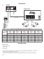
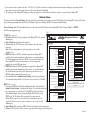
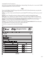
Rev. 072313 Installation Guide PLUS eBridge100SPR - EoC Receiver eBridge4SPT - 4 Port PoE/PoE+ EoC Transceiver Switch I.T.E. 43KC Overview: The eBridge4SK kit consists of eBridge100SPR and eBridge4SPT which are Coax to CAT-5 Ethernet adapters/media converters that deliver data and power over coax cable. eBridge4SK enables fast 10/100 Base-T Ethernet digital communication. eBridge4SPT allows you to upgrade your existing infrastructure by replacing a single analog device with up to four (4) PoE/PoE+ devices. eBridge100SPR passes data and sends power over the coax to the eBridge4SPT. Data transmission and power over the Coax are possible up to 300m. Maximum range from head end to the PoE camera/device is 610m, taking into consideration that up to 100m of structured cable may be deployed at each end. Built-in IP management allows for remote camera reset, monitoring and reporting via various IP protocols. eBridge4SK enables cost-effective system upgrades and eliminates the costs and labor associated with installing new network cabling. Note: Ethernet maximum distance (see Maximum Length of Coax Type vs. Camera Power/PoE Class, pg. 3). Agency Listings: • UL/CUL Listed for Information Technology Equipment (UL 60950-1). • CE approved. Input: • eBridge100SPR - 51-56VDC/60W max. power.* eBridge4SPT - powered by eBridge100SPR. Power Output: • eBridge4SPT: 4 ports PoE+ (30W) per port. • Total output power: 60W. Ethernet: • Connectivity: RJ45, auto-crossover. • Wire type: 4-pair Cat-5e or better structured cable. • Distance: up to 100m. • Speed: 10/100BaseT, half/full duplex, auto negotiation. Coax: • Distance: up to 300m. • Connectivity: BNC, RG-59/U or similar. • Throughput is rated to pass 100mbps from camera to receiver. With the proper headend equipment multiple Megapixel cameras can be used. Features: LED Indicators (cont’d): • Green LED - Power (eBridge100SPR only). • Yellow and Green LED (RJ45) IP Link status, 10/100Base-T/active. Environmental: • Operating Ambient Temperature : eBridge100SPR: -40ºC to 60ºC (-40ºF to 140ºF). eBridge4SPT: 60W: -40ºC to 75ºC (-40ºF to 167ºF). • Storage Temperature: -40ºC to 75ºC (-40ºF to 167ºF). • Humidity: 20 to 85%, non-condensing. Applications: • Retrofit digital IP cameras in an analog CCTV installation (up to four (4) IP cameras expansion per analog camera). • Works with Megapixel, HD720, HD1080 and VGA (SD) cameras (see note, pg. 2). • Extend Network link distance in an industrial environment. • Upgrade deployed CCTV Coax to a digital network in Retail, Hospitality, Arenas, Casinos, Airports, Schools, Hospitals, Transportation, etc. Mechanical: • Dimensions (H x W x D approx.): eBridge100SPR: 4.375” x 3.5” x 1” (111.125mm x 88.89mm x 25.4mm) eBridge4SPT: 1.7” x 5.23” x 8.93” (43.18mm x 132.84mm x 226.82mm) LED Indicators: • Blue LED - Coax link connection. *UL Listed Class 2 or limited power source (NetWay1D). eBridge4SK -1- Installation Instructions: Wiring methods shall be in accordance with the National Electrical Code/NFPA 70/ANSI, and with all local codes and authorities having jurisdiction. Wiring should be UL Listed and/or Recognized wire suitable for the application. eBridge100SPR and eBridge4SPT is not intended to be connected to outside plant leads and should be installed indoors within the protected premises. The eBridge100SPR and eBridge4SPT is intended for indoor use only. 1. eBridge100SPR installation: a.Secure unit to desired mounting surface with a proper fastening device utilizing the unit’s mounting hole. Unit should be mounted in proximity to Ethernet switch/network, NVR or video server. b.Connect 56VDC UL Listed Class 2 or limited power source to terminals marked [Power --- Input +] (observe proper polarity) (Fig. 1, pg. 3). Use 22AWG-16AWG wire for this connection. Caution: 56VDC will be present on coax. The other end of the coax should only be connected to the eBridge4SPT. c.Connect structured cable from Ethernet switch/NVR (network video server) to RJ45 jack marked [10/100 BaseT] (Fig. 1, pg. 3). d.Connect Coax cable to BNC connector marked [Coax] (Fig. 1, pg. 3). 2. eBridge4SPT installation: a. Affix rubber pads to eBridge4SPT for shelf installation (Fig. 9, pg. 12). b.Connect Coax cable from eBridge100SPR to BNC connector marked [Coax] located on the back of the unit (Fig. 1, pg. 3). c.Connect structured cable from PoE/PoE+ cameras/devices to RJ45 jacks marked [1-4] (Fig. 1, pg. 3). Note: The eBridge is designed to accommodate Megapixel, HD720, HD1080 and VGA (SD) cameras. It is important to note that some high resolution and high frame rate cameras may demand faster headend processing ability, such as a PC graphics card to present a quality image. If the headend processing equipment is insufficient in speed, the image may show pixelation and latency. It is advisable to pretest system if unsure. Alternatively, frame rate and resolution may be reduced to accommodate system equipment. Technical Specifications: Parameter Connections Input power requirements Indicators Description BNC for Coax link. RJ45 for Ethernet link. eBridge100SPR - 51-56VDC/60W @ max. power. eBridge4SPT - powered by eBridge100SPR. Blue: Coax Link. Yellow (RJ45 connector): On - Link, Off - No Link, Blinking - Activity. Green (RJ45 connector): On - 100Base-TX, Off - 10Base-T. Operating Ambient Temperature (UL60950-1): eBridge100SPR: -40ºC to 60ºC (-40ºF to 140ºF). eBridge4SPT: 60W: -40ºC to 75ºC (-40ºF to 167ºF). Environmental Conditions Relative humidity: 85%, +/ --- 5% Storage Temperature: --40ºC to 75ºC (-40ºF to 167ºF). Operating Altitude: --- 1000 to 6,561.679 ft. (--- 304.8 to 2000m). Regulatory Compliance UL/CUL Listed for Information Technology Equipment (UL 60950-1). CE approved. eBridge100SPR - Product: 5.1 oz. (0.144 kg.), Shipping: 7.76 oz. (0.22 kg.) Weights (approx.) eBridge4SPT - Product: 2.9 lbs. (1.32 kg), Shipping: 3.9 lbs. (1.77 kg) - 2 - eBridge4SK Fig. 1 Typical Application: eBridge100SPR eBridge4SPT (Front View) 56VDC Input Ethernet Switch Coax up to 300m PoE Output 10/100 Base-T CAT-5e up to 100m CAT-5e up to 100m NVR Network Video Server (Head End Equipment) CAT-5e up to 100m PoE/PoE+ Cameras PoE/PoE+ Cameras Maximum Length of Coax Type vs. Camera Power/PoE Class: Camera Power/ PoE Class 13W/0 or 13W/3 25W 60W 90W 120W RG59/U (23AWG) RG59/U (22AWG) 260.64m 118.9m 50.3m+ 33.5m 25m 335.28m 150.6m 63.4m+ 42.1m 31.7m RG59/U (20AWG) Max. Length (meters) 500m 239.3m+ 100.6m+ 67.1m+ 50.3m+ RG59/U (18AWG) RG6/U (18AWG) 500m 365.8m+ 160m+ 106.4m+ 80.2m+ 500m 365.8m+ 160m+ 106.4m+ 80.2m+ Internet Browser Setup Factory Default settings • IP Address: 192.168.168.168 • User Name: admin • Password: admin 1. Set the static IP address for the laptop to be used for programming to the same network IP address as the eBridge4SPT, i.e. 192.168.168.200 (the default address of the eBridge4SPT is 192.168.168.168). 2. Connect one end of the network cable to the network jack on the eBridge100SPR and the other to the network connection of the laptop. eBridge4SK -3- 3. Open a browser on the computer and enter “192.168.168.168” into the address bar. A dialog box Authentication Required will appear requesting both user name and password enter the default values here. Click on the button labeled Log In. 4. The status page of the eBridge4SPT will appear. This page displays the real time status and health of each device connected to the eBridge4SPT. Network Setup: Click on the tab labeled Network Settings. This will open the Network Setting screen. In this screen the MAC Address of the eBridge4SPT module will be found along with the programming fields for the Network Settings, Trap Receiver Settings, SNMP Port Settings and Email Settings. File Setup Help Network Settings: In the IP Address Method field select the method that the IP Address for the eBridge4SPT will be obtained “Static” or “DHCP” then follow the appropriate steps. Fig. 2 WEBVIEW INTERFACE DEVICE NAVIGATION PANEL STATIC (Fig. 2a, pg. 4): 1. IP Address: Enter the IP address assigned to the eBridge4SPT by the network Management Interface administrator. v1.99.22 2. Subnet Mask: Enter the Subnet of the network. eBridge4SPT Network Settings 3. Gateway: Enter the TCP/IP gateway of the network access point (router) Network Settings: Email Settings: being used. IP Address Method: STATIC From: [email protected] a. d. Note: Gateway configuration is required to properly receive emails IP Address: 10.0.0.113 Subject: from the device. Subnet Mask: 255.255.255.0 Username: event.report 4. HTTP Port: Enter the HTTP port number assigned to the eBridge4SPT Gateway: 10.0.0.1 module by the network administrator to allow remote access and monitoring. Password: •••••••• The default inbound port setting is 80. HTTP is not encrypted and unsecure. HTTP Port: 2713 SMTP Server: smtp.gmail.com Even though HTTP can be used for remote access it is recommended HTTPS Port: 443 SMTP Server Port: 587 primarily for use with LAN connections. MAC Address: BC:34:00:30:00:B3 Outgoing Email 1: [email protected] Submit Network Settings 5. HTTPS Port: Enter the HTTPS port number assigned to the eBridge4SPT Outgoing Email 2: [email protected] module by the network administrator to allow remote access and monitoring. Outgoing Email 3: [email protected] Trap Receiver Settings: The default inbound port setting is 443. Being encrypted and more secure, Outgoing Email 4: [email protected] b. Trap Receiver IP Address 1: 10.0.0.102 HTTPS is highly recommended for remote access. Outgoing Email 5: [email protected] Trap Receiver IP Address 2: 10.0.0.56 6. Click the button labeled Submit Network Settings. A dialog box will display Trap Receiver IP Address 3: 62.19.75.80 “New network settings will take effect after the server is rebooted”. Click OK. Dashboard Linq Lab Linq2 “A” Lab Linq2 “B” Netway Netway16M Netway4ES Netway8M Netway1DWPM FireSwitch FireSwitch eBridge eBridge4SPT eBridge200WPM eBridge16PCRX Status Setup Network Settings Security Settings Events Log Site ID: RJ Sports Wear Site ID: RJ Sports Wear Test Email Trap Receiver IP Address 4: 45.165.245.146 DHCP (Fig. 2a, pg. 4): Trap Receiver IP Address 5: 50.74.175.125 1. After selecting DHCP in the IP Address Method field click the button labeled Submit Trap Receiver IP Settings Submit Network Settings. A dialog box will display “New network settings will SNMP Port Settings: take effect after the server is rebooted”. Click OK. Next click on theLOGbutton c. SNMP Port: 161 labeled Reboot Server. After rebooting the eBridge4SPT will be set in the Trap Message Port: 162 DHCP mode. The IP address will be assigned by the router when the Submit Port Settings eBridge4SPT is connected to the network. It is recommended to have the assigned IP Address reserved to ensure continued access (see the network administrator). 2. Subnet Mask: When operating in DHCP the router will assign the subnet mask values. 3. Gateway: TCP/IP gateway of the network access point (router) being used will be displayed. Restore Default Submit Email Settings Restore Factory Settings Reboot Server > eBridge16PCRX [50.74.149.196:2717] added. > eBridge200WPM [50.74.149.196:2712] added. > eBridge4SPT [50.74.149.196:2713] added. > FireSwitch [ 50.74.149.196:2710 ] added. > Netway1DWPM [ 50.74.149.196:2716 ] added. > NetWay8M [ 50.74.149.196:2715 ] added. > Netway4ES [ 50.74.149.196:2714 ] added. > Netway16M [ 50.74.149.196:2707 ] added. > Lab Linq2 “B” [ 50.74.149.196:2703 ] added. Ethernet adapter detected. - 4 - Trap receiver Port: 162 eBridge4SK Site ID 4. 5. 6. HTTP Port: Enter the HTTP port number assigned to the eBridge4SPT module by the network administrator to allow remote access and monitoring. The default inbound port setting is 80. HTTP is not encrypted and unsecure. Even though HTTP can be used for remote access it is recommended primarily for use with LAN connections. HTTPS Port: Enter the HTTPS port number assigned to the eBridge4SPT module by the network administrator to allow remote access and monitoring. The default inbound port setting is 443. Being encrypted and more secure, HTTPS is highly recommended for remote access. Click the button labeled Submit Network Settings. A dialog box will display “New network settings will take effect after the server is rebooted”. Click OK. Trap Receiver Settings (Fig. 2b, pg. 4): 1. Enter up to five SNMP trap receiver IP addresses. When accessing the eBridge4SPT remotely check with the network administrator for proper configuration. 2. Click the button labeled Submit Trap Receiver IP Settings. A dialog box will display “New Trap Receiver IP settings will take effect after the server is rebooted”. Click OK. SNMP Port Settings (Fig. 2c, pg. 4): SNMP uses the default port 161 for general SNMP messages and port 162 for SNMP trap messages. In the event these port need to be changed enter the new port numbers assigned by the network administrator. Click the button labeled Submit Port Settings. A dialog box will display “New SNMP port settings will take effect after the server is rebooted”. Click OK. Email Settings (Fig. 2d, pg. 4): The eBridge4SPT can send emails via an in-house email server, email service provider (i.e. Gmail, Yahoo) or Altronix default email service. In-house email server: 1. From: Enter the email address assigned to the eBridge4SPT module by the system administrator. 2. Subject: Identify the location of the ebridge4SPT (i.e. the Site ID). 3. Username: Enter the username associated with the eBridge4SPT module email address. 4. Password: Enter the username password. 5. SMTP server IP: Enter the SMPT IP address of the in-house email server. 6. SMTP server Port: Enter the SMPT port assigned to the in-house email server. 7.Outgoing Email Address 1-5: Enter up to five outgoing email addresses. 8. Click the button labeled Submit Email Settings email setting will be saved. Email service provider: 1. From: Enter the email address for the eBridge4SPT module. 2. Subject: Identify the location of the eBridge4SPT (i.e. the Site ID) 3. Username: Enter the username associated with the eBridge4SPT module email address. 4. Password: Enter the username password 5. SMTP server IP: Enter the SMPT IP address of the email service provider. 6. SMTP server Port: Enter the email SMPT port number. The default SMPT email ports are 25 or 465 unless otherwise specified. 7. Outgoing Email Address 1-5: Enter up to five outgoing email addresses. 8. Click the button labeled Submit Email Settings email setting will be saved. Altronix default email service: 1. All required sender and network fields have already been populated. 2. Outgoing Email Address 1-5: Enter up to five outgoing email addresses. 3. Click the button labeled Submit Email Settings. Email settings will be saved. To test the email setup click the button labeled Test Email. An email will be sent to all Outgoing email addresses. If the test email is not received contact the eBridge4SK -5- network administrator and repeat the email setup sets. After all fields have been programed click the button labeled Reboot Server. A dialog box will display “Please allow up to 30 sec. for server to reboot”. Click OK. All programmed information will be saved after the server has rebooted. Setup: Click on the tab labeled Setup. The eBridge4SPT setup page will open. In this screen the Site ID, Date/Time and Port identification are setup, along with the ability to enable and disable individual ports. Site ID (Fig. 3a, pg. 6): Enter a descriptive name that will identify the location of the eBridge4SPT. The Site ID will appear in both the trap message and email notifications. Date/Time (Fig. 3b, pg. 6): Time and Date can be entered two different ways manually or by syncing the date and time with the host computer. Manual setup (Fig. 3b, pg. 6): Individually select the appropriate information for each of the required field then click Update. This will update time of the eBridge4SPT to the programmed information. The manual setup can be used when programming devices installed in one time zone and monitored in another. Sync Setup (Fig. 3b, pg. 6): Clicking the button labeled Sync Date/Time with computer will set the eBridge4SPT to the time of the host computer. Port ID (Fig. 3c, pg. 6): Enter a descriptive name and/or location of the device connected to the port. Port Status (Fig. 3d, pg. 6): Individual ports can be enabled or disabled by clicking the button labeled Enable Port/Disable Port. This feature allows unused ports to be disabled and also can be used to reboot a connected device by cycling power OFF and ON. After all fields have been programmed click on the button labeled Save Settings. Fig. 3 Management Interface Status Setup Network Settings Security Settings v1.99.22 Events Log eBridge4SPT Site ID: Setup a. RJ Sports Wear Update Site ID Trap Receiver Settings: Jul 15 b. 2015 Port [ 9 : 32 Port ID : 53 am ] Update c. Sync Date/Time with computer Port Status d. 1 Main Entrance Enabled Disable Port 2 Production Enabled Disable Port 3 Receiving Enabled Disable Port 4 Shipping Enabled Disable Port Save Settings - 6 - eBridge4SK Man Security Settings: Status Setup Network Settings Security Settings Click on the tab labeled Security Settings. The eBridge4SPT security setting page will open. In this screen the SSL certificate and Key will be entered, the SSL can be enabled or disabled and new username and password can be set. Using an SSL certificate will ensure that when remotely accessing the eBridge4SPT all eBridge4SPT data has been encrypted and there for secure through the assigned HTPPS Port. Site ID: RJ Sports Wear Fig. 4a SSL Certificate Setting (Fig. 4a, pg. 7): SSL Certificate Settings: Generating a self-signed SSL Certificate and Key. 1. State: Two letter code representing the state where the organization is located. State: NY 2. Location: The city where the organization is located. 3. Organization: The legal name of the organization. This should not be abbreviated, Locality: Brooklyn and should include suffixes such as Inc., Corp, or LLC. Organization: RJ Sports Wear Inc. 4. Unit Name: Name of the device. 5. Common Name: Domain name or IP address of the server. This is typically assigned Unit Name: eBridge4SPT by the network administrator. 6. Email Address: An email address used to contact the organization. Common Name: 192.168.168.168 After all field have been completed click on the button labeled Submit SSL Settings. A dialog box will appear “Please allow up to 30 secs. for server to reboot”. Click OK. A self-signed SSL certificate Email Address: [email protected] will be generated with the information provided in the “SSL certificate settings” fields. The certificate will be valid for 500 days, and time stamped with the time settings present on the Submit SSL Settings eBridge4SPT module. The date and time must be synced with the host computer before generating an SSL certificate. Events L Management Interface Status Setup Network Settings Security Settings Using a private SSL certificate and Key (Fig. 4b, pg. 7): eBridge4SPT Private SSL Certificates and Keys uploaded using the Altronix Dashboard. Site ID: RJ must Sportsbe Wear For additional information refer to the Altronix Dashboard setup/user manual section Updating firmware / SSL certificate and Key. SSL Certificate Settings: SSL Status: Certificate Status: Key Status: SSL State: State: NY Certificate OK = Valid SSL Certificate Bad Certificate = Invalid SSL Certificate Locality: Brooklyn No Certificate = a Valid SSL Certificate has not been loaded. Key OK = Valid SSL Key Organization: RJ Sports Wear Inc. Bad Key = Invalid SSL Key Unitnot Name: No Key = a Valid SSL Key has been eBridge4SPT loaded. The SSL of the eBridge4SPT can be turned on and off by click the Common Name: 192.168.168.168 button labeled Turn SSL On/Turn SSL Off. Email Address: [email protected] Submit SSL Settings v1.99.22 Events Log Security Settings Friday, Jul 31 2015 [9:10 am] Fig. 4b SSL Status: Certificate Status: Certificate Ok Key Status: Key Ok SSL State: Off Turn SSL On Change Username and Password: Username: RJsports Password: ****** Confirm Password: ****** Save Username and Password eBridge4SK -7- Locality: Brooklyn SSL State: Organization: RJ Sports Wear Inc. Change Username and Password (Fig. 4c, pg. 8): Unit Name: eBridge4SPT 1. Username: Enter the new Username (up to 32 characters) required to access the eBridge4SPT. 2. Password: Enter the new Password (up to 32 alpha numeric required to access Common Name: characters) 192.168.168.168 the eBridge4SPT. Email Address: [email protected] 3. Confirm Password: Reenter the new Password. Click the button labeled Save Username and Password. A dialog box with appear, Submit SSL Settings “New settings have been applied”. Click OK. After saving, the new username and password will be active. Off Turn SSL On Fig. 4c Change Username and Password: Username: RJsports Password: ****** Confirm Password: ****** Save Username and Password Management Interface Event Log and Heartbeat Timer: Click on the tab labeled Event Log. The eBridge4SPT event log will open. This screen will display the event log along with the heartbeat timer setup. Event Log: The event log will display the 50 most recent events. To update the Event Log click the button labeled Display/Refresh Log. Fig. 5 Status Setup Network Settings Security Settings Events Log v1.99.22 Events Log Friday, Jul. 31 2015 [9:01 am] Site ID: RJ Sports Wear Display/Refresh Log - 8 - Heartbeat Timer Settings Last update: Fri Jul 31 2015 09:01:37 GMT-0400 (Eastern Daylight Time) Fri Jul 31 2015 08:05:03 GMT-0400 (Eastern Daylight Time) : eBridge4SPT@eBridge4SPT@Port3 Disabled Fri Jul 31 2015 08:10:12 GMT-0400 (Eastern Daylight Time) : eBridge4SPT@eBridge4SPT@Port1 Disabled Fri Jul 31 2015 08:15:24 GMT-0400 (Eastern Daylight Time) : eBridge4SPT@eBridge4SPT@Port2 Disabled Fri Jul 31 2015 08:20:36 GMT-0400 (Eastern Daylight Time) : eBridge4SPT@eBridge4SPT@Port4 Disabled Fri Jul 31 2015 08:35:17 GMT-0400 (Eastern Daylight Time) : eBridge4SPT@eBridge4SPT@Port3 Enabled Fri Jul 31 2015 08:40:28 GMT-0400 (Eastern Daylight Time) : eBridge4SPT@eBridge4SPT@Port1 Enabled Fri Jul 31 2015 08:45:43 GMT-0400 (Eastern Daylight Time) : eBridge4SPT@eBridge4SPT@Port2 Enabled Fri Jul 31 2015 08:50:00 GMT-0400 (Eastern Daylight Time) : eBridge4SPT@eBridge4SPT@Port4 Enabled eBridge4SK Heartbeat Timer: The heartbeat timer will send a trap message indicating that the eBridge4SPT is still connected and communicating. Setting the Heart Beat Timer: 1. Click the button labeled Heartbeat Timer Setting. 2. Select the desired time between heartbeat messaging in the Days, Hours, Minutes and Seconds in corresponding fields. 3. Click the button labeled Submit to save settings. Fig. 6 Management Interface Status Setup Network Settings Security Settings v1.99.22 Events Log Events Log Friday, Jul. 31 2015 [9:01 am] Site ID: RJ Sports Wear Display/Refresh Log Last update: Fri Jul 31 2015 09:01:37 GMT-0400 (Eastern Daylight Time) Heartbeat Timer Settings Heartbeat Timer Settings: 1 Days 0 Hours 0 Minutes 0 Seconds Submit Updating Firmware: Firmware updates must be done using the Altronix Dashboard. For additional information refer to the Altronix Dashboard setup/user manual’s section Updating firmware / SSL certificate and Key. eBridge4SK -9- Status Screen: a. Class Power (Watts) (Fig. 7a, pg. 10): Wattage required by the PoE class of the device. b. Actual Power Draw (Watts) (Fig. 7b, pg. 10): Amount of watts being drawn by the connected device. c. Device Status (Fig. 7c, pg. 10): Active or Inactive. d. Port Status (Fig. 7d, pg. 10): Indicates whether port is Enabled or Disabled. Fig. 7 WEBVIEW INTERFACE Management Interface Status Setup Network Settings Security Settings Site ID v1.99.22 Events Log eBridge4SPT Status Wednesday, Jul. 15 2015 [9:35 am] Site ID: RJ Sports Wear Port 1 : Main Entrance Class Power Actual Power Draw (Watts) (Watts) a. 6.49 b. 3.85 Port 3 : Receiving Class Power Actual Power Draw (Watts) (Watts) 6.49 3.25 Device Status c. Active Port Status d. Enabled Device Status Port Status Active Enabled Port 2 : Production Class Power Actual Power Draw (Watts) (Watts) 6.49 3.90 Port 4 : Shipping Class Power Actual Power Draw (Watts) (Watts) 6.49 3.25 Device Status Port Status Active Enabled Device Status Port Status Active Enabled Connection Status: OK d. d. d. rt: 162 - 10 -eBridge4SK Notes: eBridge4SK - 11 - PoE Output 10/100 Base-T 5.23” (132.84mm) Coax SLOC link LED 1.7” (43.18mm) 8.93” (226.82mm) Fig. 8 8.42” (213.87mm) eBridge4SPT Chassis Mechanical Drawing & Dimensions (H x W x D approx.): 1.7” x 5.23” x 8.93” (43.18mm x 132.84mm x 226.82mm) Shelf Installation A 1- Position and affix rubber pads (C) (included) at each corner on the bottom of the unit (Fig. 9). 2- Place unit in desired location. Fig. 9 Left side B Mounting Hardware (Included): C Four (4) rubber pads C Rubber Feet Altronix is not responsible for any typographical errors. 140 58th Street, Brooklyn, New York 11220 USA, 718-567-8181, fax: 718-567-9056 website: www.altronix.com, e-mail: [email protected]. Lifetime Warranty, Made in U.S.A. IIeBridge4SKI25O MEMBER - 12 -eBridge4SK