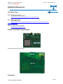
1
Digital Voice Systems, Inc. The Speech Compression Specialists AMBE-20x0™-HDK Development Board Version 2.3 07, September User’s Manual Preliminary AMBE-20x0™-HDK Development Board User’s Manual Version 2.3 07, September Copyright, 2007 Digital Voice Systems, Inc 234 Littleton Road Westford, MA 01886 This document may not, in whole or in part be copied, photocopied, reproduced, translated, or reduced to any electronic medium or machine readable form without prior consent in writing from Digital Voice Systems, Incorporated. Every effort has been made to ensure the accuracy of this manual. However, Digital Voice Systems, Inc. makes no warranties with respect to the documentation and disclaims any implied warranties of merchantability and fitness for a particular purpose. Digital Voice Systems, Inc. shall not be liable for any errors or for incidental or consequential damages in connection with the furnishing, performance, or use of this manual or the examples herein. The information in this document is subject to change without notice. Trademarks AMBE-20x0™-HDK Development Board and AMBE-2000™ Vocoder Chip, AMBE-2020™ Vocoder Chip are trademarks of Digital Voice Systems, Inc. AMBE® is a registered trademark of Digital Voice Systems, Inc. Other product names mentioned may be trademarks or registered trademarks of their respective companies and are the sole property of their respective manufacturers. All Rights Reserved Data subject to change AMBE-20X0™-HDK Development Board User’s Manual (Preliminary) Information – Section AMBE-20x0™-HDK Development Board END USER License Agreement *** Important Read Carefully *** This end user license agreement is a legal agreement between the customer (the END USER) and Digital Voice Systems, Inc. (DVSI) covering the terms and conditions under which DVSI's proprietary software, documentation and other material which may be provided with the AMBE-20x0™-HDK Development Board is licensed to the END USER. 1.0 Preliminary Statements and Definitions 1.1 “END USER” shall mean the person and/or organization to whom the AMBE2000™ Vocoder Chip and/or AMBE-20x0™-HDK Development Board was delivered or provided to as specified in the purchase order or other documentation. In the event that the END USER transfers his rights under this license to a third party as specified in section 2.2, then this third party shall become an “END USER”. 1.2 Digital Voice Systems, Inc. (DVSI) has developed a voice coding method and algorithm (the “Technology”) based on the Advanced Multi-Band Excitation (“AMBE”) voice coder. The technology codes speech at bit rates of 2.4 to 9.6 kilobits per second (kbps) including error correction bits. 1.3 "AMBE Voice Compression Software" shall mean the speech coding software and/or firmware integrated into the AMBE-2000™ Vocoder chip integrated circuit. 1.4 "Voice Codec" shall mean the AMBE-2000™ Vocoder Chip integrated circuit, the AMBE Voice Compression Software, firmware and associated documentation, including modifications, enhancements and extensions made by or for Digital Voice Systems, Inc. (DVSI) and including circuit diagrams, timing diagrams, logic diagrams, layouts, operating instructions and user manuals. 1.5 DVSI represents that it owns certain “Proprietary Rights” in the Technology and the AMBE Voice Compression Software, including patent rights in the Technology, and patent rights, copyrights, and trade secrets in the AMBE Voice Compression Software. 2.0 License Granted 2.1 Subject to the conditions herein and upon initial use of the AMBE-2000™ Vocoder Chip and/or AMBE-20x0™-HDK Development Board, DVSI hereby grants to END USER a non-exclusive, limited license to use the AMBE® Voice Compression Software in machine readable form solely on the AMBE-2000™ Vocoder Chip. Title to the AMBE® Voice Compression Software remains with DVSI. No license is granted for use of the AMBE® Voice Compression Software on other than the AMBE-2000™ Vocoder Chip. No license, right or interest in any trademark, trade name or service mark of DVSI is granted under this Agreement. 2.2 END USER shall not copy, extract, de-compile, reverse engineer or disassemble the AMBE® Voice Compression Software contained in the AMBE2000™ Vocoder Chip. 3.0 Transfer of License 3.1 The END USER shall have the right to transfer the AMBE-2000™ Vocoder Chip and/or AMBE-20x0™-HDK Development Board and all rights under this Agreement to a third party by either (i) providing the third party with a copy of this Agreement or (ii) providing the third party with an agreement written by the END USER ( hereinafter “END USER Agreement”) so long as the END USER Agreement is approved in writing by DVSI prior to transfer of the AMBE-2000™ Vocoder Chip and/or AMBE-20x0™-HDK Development Board. The END USER Agreement shall contain comparable provisions to those contained herein for protecting the Proprietary Information from disclosure by such third party. Third parties shall agree to accept all the terms and conditions under either Agreement or the END USER Agreement. 7.0 Proprietary Information 7.1 The parties agree that the AMBE Voice Compression Software and/or AMBE20x0™-HDK Development Board shall be considered Proprietary Information. 7.2 Except as otherwise provided in this Agreement, END USER shall not use, disclose, make, or have made any copies of the Proprietary Information, in whole or in part, without the prior written consent of DVSI. 8.0 Limited Warranty 8.1 DVSI warrants the AMBE-20x0™-HDK Development Board to be free from defects in materials and workmanship under normal use for a period of ninety (90) days from the date of delivery. 8.2 Except as stated in Section 7.1, the AMBE-20x0™-HDK Development Board is provided "as is" without warranty of any kind. DVSI does not warrant, guarantee or make any representations regarding the use, or the results of the use, of the Voice Codec with respect to its correctness, accuracy, reliability, correctness or otherwise. The entire risk as to the results and performance of the Voice Codec and/or AMBE20x0™-HDK Development Board is assumed by the END USER. After expiration of the warranty period, END USER, and not DVSI or its employees, assumes the entire cost of any servicing, repair, replacement, or correction of the Voice Codec and/or AMBE20x0™-HDK Development Board. 8.3 DVSI represents that, to the best of its knowledge, it has the right to enter into this Agreement and to grant a license to use the AMBE Voice Compression Software and/or AMBE-20x0™-HDK Development Board to END USER. 8.4 Except as specifically set forth in this Section 7.0, DVSI makes no express or implied warranties including, without limitation, the warranties of merchantability or fitness for a particular purpose or arising from a course of dealing, usage or trade practice, with respect to the Voice Codec and/or AMBE-20x0™-HDK Development Board. Some states do not allow the exclusion of implied warranties, so the above exclusion may not apply to END USER. No oral or written information or advice given by DVSI or its employees shall create a warranty or in any way increase, the scope of this warranty and END USER may not rely on any such information or advice. The limited warranties under this section 7.0 give END USER specific legal rights, and END USER may have other rights that vary from state to state. 9.0 Limitation of Liability 9.1 In no event shall DVSI be liable for any special, incidental, indirect or consequential damages resulting from the use or performance of the Voice Codec and/or AMBE20x0™-HDK Development Board whether based on an action in contract, tort (including negligence) or otherwise (including, without limitation, damages for loss of business profits, business interruption, and loss of business information), even if DVSI or any DVSI representative has been advised of the possibility of such damages. 9.2 Because some states do not allow the exclusion or limitation of liability for consequential or incidental damages, the above limitations may not apply to END USER. 9.3 DVSI's maximum liability for damages arising under this Agreement shall be limited to 20% (twenty percent) of the fees paid by END USER for the particular Voice Codec and/or AMBE-20x0™-HDK Development Board which caused the damages or that is the subject matter of, or is directly related to, the cause of action. 10.0 Taxes 4.0 Term and Termination 4.1 This Agreement is effective upon initial delivery of the Voice Codec and shall remain in effect until terminated in accordance with this agreement. 4.2 This Agreement shall terminate automatically without notice from DVSI if END USER fails to comply with any of the material terms and conditions herein. END USER may terminate this Agreement at any time upon written notice to DVSI certifying that END USER has complied with the provisions of Section 3.3. 4.3 Upon termination of this Agreement for any reason, END USER shall: (i) return all AMBE-2000™ Vocoder Chips and/or AMBE-20x0™-HDK Development Boards purchased or acquired, or in Licensee’s possession, to DVSI; (ii) have no further rights to any AMBE® Voice Compression Software or the Technology without a separate written license from DVSI; (iii) discontinue all use of the AMBE-2000™ Vocoder Chips and/or AMBE-20x0™-HDK Development Boards; 5.0 Payments 5.1 In consideration of the materials of the AMBE-20x0™-HDK Development Board, and in consideration of the license and rights in the AMBE Voice Compression Software granted by DVSI, and in consideration of DVSI's performance of its obligations hereunder, END USER agrees to pay to DVSI the fee specified in DVSI's invoice. 10.1 All payments required under Section 4.0 or otherwise under this Agreement are exclusive of taxes and END USER agrees to bear and be responsible for the payment of all such taxes (except for taxes based upon DVSI's income) including, but not limited to, all sales, use, rental receipt, personal property or other taxes which may be levied or assessed in connection with this Agreement. 11.0 Export 11.1 United States export laws and regulations prohibit the exportation of certain products or technical data received from DVSI under this Agreement to certain countries except under a special validated license. As of November 30, 1999 the restricted countries are: Libya, Cuba, North Korea, Iraq, Serbia, Taliban in Afghanistan, Sudan, Burma, Yugoslavia and Iran. The END USER hereby gives its assurance to DVSI that it will not knowingly, unless prior authorization is obtained from the appropriate U.S. export authority, export or re-export, directly or indirectly to any of the restricted countries any products or technical data received from DVSI under this Agreement in violation of said United States Export Laws and Regulations. DVSI neither represents that a license is not required nor that, if required, it will be issued by the U.S. Department of Commerce. Licensee shall assume complete and sole responsibility for obtaining any licenses required for export purposes. 6.0 Proprietary Notices 12.0 Governing Law 6.1 END USER shall not remove any copyright or proprietary notice on the AMBE-2000™ Vocoder Chip or on the AMBE Voice Compression Software and/or AMBE-20x0™-HDK Development Board. 12.1 This Agreement is made under and shall be governed by and construed in accordance with the laws of the Commonwealth of Massachusetts, except that body of law governing conflicts of law. If any provision of this Agreement shall be held unenforceable by a court of competent jurisdiction, that provision shall be enforced to the maximum extent permissible, and the remaining provisions of this Agreement shall remain in full force and effect. AMBE-20X0™-HDK Development Board User’s Manual (Preliminary) Information – Section Special Handling Instructions To avoid damage from the accumulation of a static charge, industry standard electrostatic discharge precautions and procedures must be employed during handling and installation the AMBE-20x0™-HDK Development Board. Read Instructions and Users Manual – All of the safe handling and operating instructions should be read before integration of the AMBE-20x0™-HDK Development Board begins. Failure to exercise reasonable care and to follow all instructions and heed all warnings may result in injury to property or to individuals. Retain Instructions - The handling and operating instructions should be retained for future reference. Follow Instructions - All operating and use instructions should be followed. Storage To insure maximum shelf life in long term storage, AMBE-20x0™-HDK Development board should be kept in an a static shield, moisture controlled package at <40°C and <90% Relative Humidity Installation Ventilation - The AMBE-20x0™-HDK Development Board unit should be situated so that its location or position does not interfere with proper ventilation and air circulation around the board. Heat - The AMBE-20x0™-HDK Development Board unit should be situated away from devices that could act as a heat source such as an amplifier. Power Sources - The AMBE-20x0™-HDK Development Board should be connected to a power source only of the type described in this Users Manual. AMBE-20X0™-HDK Development Board User’s Manual (Preliminary) Section – Table of Contents Table of Contents Preliminary Section 1 INTRODUCTION ....................................................................1 GENERAL INFORMATION .........................................................................................1 OVERVIEW ............................................................................................................2 AMBE-2000™ INSIDE ...........................................................................................3 AMBE-2000™ Vocoder Chip Applications ..................................................4 Data Rates from 2000bps to 9600bps ........................................................4 FEC .............................................................................................................4 Voice Activation Detection (VAD)................................................................5 Comfort Noise Insertion (CNI).....................................................................5 Echo Cancellation .......................................................................................5 W HAT’S INCLUDED WITH THE HDK .........................................................................5 Section 2 CONNECTORS, TEST POINTS & INDICATORS ...........................6 OVERVIEW ............................................................................................................6 DC POWER ...........................................................................................................7 ANALOG AUDIO I/O................................................................................................7 HANDSET ..............................................................................................................8 RS-232 CONNECTIONS .........................................................................................8 Channel I/O .................................................................................................9 Console Out ..............................................................................................10 JTAG CONNECTIONS ..........................................................................................10 PLD JTAG Interface ..................................................................................11 TEST POINTS ......................................................................................................11 AMBE-2000™ ...........................................................................................12 Analog I/O .................................................................................................12 HDK BOARD STATUS INDICATOR LEDS ................................................................13 Section 3 HDK CONFIGURATION & DATA RATE SELECTION .................14 OVERVIEW ..........................................................................................................14 BOARD RESET.....................................................................................................14 AMBE-2000™VOCODER SET-UP VIA DIP-SWITCHES ...........................................14 Slide Dip-Switch Settings ..........................................................................15 Jumpers ....................................................................................................17 HDK RS-232 INTERFACE SET-UP VIA KEYPAD .....................................................17 Section 4 COMMUNICATION VIA CHANNEL INTERFACE ..........................18 OVERVIEW ..........................................................................................................18 BASIC OPERATION ...............................................................................................18 “HDK Format” Packet Data Structure........................................................19 Data Structure “AMBE-2000 Format” Packet............................................20 HDK AUDIO CODEC LOOP BACK ..........................................................................21 LOOP BACK HDK AUDIO CODEC AND AMBE-2000™ VOCODER CHIP ...................21 CONNECTING TWO BOARDS TOGETHER VIA RS-232 CHANNEL I/O.........................22 CONNECTING THE CONSOLE OUT UART SERIAL CONNECTION TO A PC ................23 CONNECTING THE RS-232 CHANNEL I/O TO A PC ................................................25 DEMONSTRATION SOFTWARE...............................................................................25 RUNNING THE AMBE_HDK.EXE FILE .......................................................................26 Command Line Options ............................................................................26 Section 5 SPECIFICATIONS ................................................................28 OVERVIEW ..........................................................................................................28 AMBE-20X0™-HDK Development Board User’s Manual (Preliminary) Section – Table of Contents BOARD CONNECTIONS ........................................................................................ 28 AUDIO I/O CONNECTIONS .................................................................................... 28 HEADER CONNECTIONS....................................................................................... 30 ELECTRICAL INPUT .............................................................................................. 30 MECHANICAL ...................................................................................................... 30 JTAG CONNECTIONS SETUP & CONTROL ............................................................ 30 Section 6 ADDITIONAL RESOURCES ...................................................31 THIRD PARTY TOOLS........................................................................................... 31 PRINTED CIRCUIT BOARD LAYOUT DIAGRAM ........................................................ 31 SCHEMATICS....................................................................................................... 31 Analog I/O ................................................................................................. 32 MSP .......................................................................................................... 33 Serial......................................................................................................... 34 Xilinx ......................................................................................................... 35 Codec ....................................................................................................... 37 Configuration............................................................................................. 38 Power........................................................................................................ 39 AMBE-2000™ Vocoder Chip .................................................................... 40 MSP430 INPUT/OUTPUT PIN DESCRIPTION .......................................................... 41 XILINX PLD INPUT/OUTPUT PIN DESCRIPTION .................................................... 41 SOFTWARE DEVELOPMENT .................................................................................. 42 REFERENCE DESIGNS ......................................................................................... 42 Application Information ............................................................................. 43 Additional Reference Material................................................................... 43 Section 7 SUPPORT ..........................................................................44 DVSI CONTACT INFORMATION ............................................................................. 44 List of Tables TABLE 1 AMBE-20X0 HDK™ FEATURES ............................................................................... 1 TABLE 2 AMBE-2000™ APPLICATIONS ................................................................................. 4 TABLE 3 TOP PANEL CONNECTORS ........................................................................................ 6 TABLE 4 HANDSET PINOUT .................................................................................................... 8 TABLE 5 CONSOLE OUT UART SERIAL PORT SETTINGS ....................................................... 10 TABLE 6 MSP430 JTAG HEADER (JP8) .............................................................................. 10 TABLE 7 PLD JTAG PIN OUT ............................................................................................... 11 TABLE 8 AMBE-2000 TEST POINTS ..................................................................................... 12 TABLE 9 ANALOG TEST POINTS (JP2) .................................................................................. 12 TABLE 10 ANALOG TEST POINT (JP3) .................................................................................. 12 TABLE 11 ANALOG TEST POINT (JP4) .................................................................................. 12 TABLE 12 BOARD STATUS LED'S ......................................................................................... 13 TABLE 13 DIP SWITCHES 1 AND 2 SETTINGS ........................................................................ 15 TABLE 14 STANDARD RATE TABLE FOR AMBE-20X0............................................................ 16 TABLE 15 CHANNEL INTERFACE SELECTION TABLE ............................................................... 16 TABLE 16 UNFRAMED BIT PER W ORD SELECTION TABLE ...................................................... 17 TABLE 17 JUMPER SETTINGS ............................................................................................... 17 TABLE 18 “HDK FORMAT” PACKET STRUCTURE .................................................................. 19 TABLE 19 EXAMPLE PACKET SIZE FOR VARIOUS COMPRESSSED VOICE DATA RATES ............ 20 TABLE 20 DIP SWITCH SETTINGS FOR FILE I/O..................................................................... 26 TABLE 21 FILE I/O COMMAND LINE OPTIONS ........................................................................ 26 List of Figures FIGURE 1 BASIC BLOCK DIAGRAM OF THE AMBE-2000 HDK BOARD ........................................ 3 FIGURE 2 AMBE-20X0™-HDK DEVELOPMENT BOARD TOP ................................................... 6 AMBE-20X0™-HDK Development Board User’s Manual (Preliminary) Section – Table of Contents FIGURE 3 POWER INPUT CONNECTION....................................................................................7 FIGURE 4 CONSOLETERMINAL SETTINGS ................................................................................9 FIGURE 5 CONNECTING TWO HDK BOARDS TOGETHER ..........................................................9 FIGURE 6 PHOTO OF JTAG CONNECTIONS ...........................................................................11 FIGURE 7 RESET SWITCH.....................................................................................................14 FIGURE 8 VOCODER SETTINGS SWITCHES SW1 AND SW2 ...................................................15 FIGURE 9 CONNECTING TWO HDK BOARDS TOGETHER USING A NULL MODEM RS-232 CABLE. 22 FIGURE 10 RS-232 NULL MODEM CABLE PIN-OUT FOR CONNECTING TWO HDK BOARDS TOGETHER ...........................................................................................................................................22 FIGURE 11 RS-232 STRAIGHT THROUGH CABLE PIN-OUT FOR CONNECTING HDK BOARD AND PC TOGETHER...........................................................................................................................23 AMBE-20x0™-HDK Development Board User’s Manual (Preliminary) Section 1 – Introduction Introduction Digital Voice Systems, Inc. The Speech Compression Specialists General Information The Digital Voice Systems, Inc. (DVSI) AMBE-20x0™-HDK Development Board is an comprehensive, evaluation, test and development platform that helps product designers and manufacturing engineers TM gain experience with the low-bit-rate AMBE-2000 and AMBE-2020™ Vocoder Chips. The AMBE20x0™ HDK is ideal for comparing voice quality at various rates, analyzing the compressed voice data I/O stream and establishing interface requirements. This valuable knowledge gives engineers the insight required to start prototyping their own low-bit-rate communication systems quickly and easily thereby decreasing development costs and speed up a new product’s time to market. The AMBE-20x0™ HDK employs DVSI’s successful AMBE-2000™ vocoder chip that has been implemented in communication systems, including push-to-talk land mobile radio, and wireless telephony throughout the world. The AMBE-2000™ Vocoder Chip contains proprietary software that ® implements the Advanced Multi-Band Excitation AMBE voice compression algorithm. The AMBE2000™Vocoder Chip is capable of speech and FEC data rates, from 2.0 Kbps to 9.6 Kbps (in 50 bps increments). This data rate flexibility makes the AMBE-20x0™ HDK a cost efficient design and development tool for high performance, low bandwidth voice communication applications. AMBE-20x0™-HDK Development Board Features Flexible Bit Rate Selection - Real Time, High Quality, Speech Compression Data rates from 2000 bps to 9600 bps. Straightforward Vocoder Configuration - Set-up via the on-board keypad, dipswitches or jumpers. Variety of Advanced Features - Soft decision FEC, Voice Activity Detection (VAD), adaptive Comfort Noise Insertion (CNI) and support for DTMF tones. Easy to duplicate design - schematic details, example microcontroller software and PLD code, provides engineers a detailed reference for designing custom circuits. Standard RS-232 asynchronous interface - provides a channel connection to another AMBE-20x0™ HDK or other RS-232 device for real-time communication. Single voltage design - minimizes circuit complexity because all AMBE-20x0™ HDK components are powered using a 3.3 Volt supply. 16-bit high performance codec - provides quality analog audio I/O to an RCA jack (4-wire) and interface and to a handset (2-wire). Table 1 AMBE-20x0 HDK™ Features DVSI Confidential Proprietary Page 1 AMBE-20x0™-HDK Development Board User’s Manual (Preliminary) Section 1 – Introduction Overview The AMBE-20x0™ Hardware Development Kit (HDK) is designed to streamline the development of products engineered around the AMBE-2000™ Vocoder chip. The AMBE- 20x0™ HDK is a completely functional system from the analog audio interface to the digital channel interface. The straightforward design of the board provides a variety of user interfaces and test points that allow designers to rapidly prototype their own AMBE-2000™ designs. Digital Voice Systems’ AMBE-2000™ Vocoder Chip is the core of the AMBE-20x0™ HDK. All of the supporting chips on the board were chosen for their low cost, ease of use and wide availability. The control, I/O and timing of the board is handled by the Texas Instruments MSP430 microprocessor unit (MCU). The MSP-430 flash image is easily programmed using an MSP430-FET serial programmer a low cost development tool from Texas Instruments. The HDK incorporates a Xilinx programmable logic device (PLD). This is used for the serial to parallel conversion between the AMBE-2000™ Vocoder Chip and the MSP430 microcontroller. The PLD is programmed using a XILINX ISP. The AMBE-20x0 HDK is designed to run in a standalone nature. The RS-232 interface can looped back so that the input goes through the AD/DA process the result is sent to the output. The AMBE- 20x0™ HDK is also a stand-alone voice processing board, equipped with connections for analog audio I/O, a RS-232 serial UART port communication channel interface, and a RS-232 control port. The AMBE-20x0™ HDK can demonstrate the capabilities and benefits of a low-bit-rate vocoder in real time communication systems, without investing much time in engineering. Once a new product design is complete and manufacturing begins the AMBE-20x0™ HDK can then be used to simulate actual system conditions as a quality control reference standard. The HDK contains everything needed to begin testing and running a voice compression communication system without having to install additional hardware / software. DVSI Confidential Proprietary Page 2 AMBE-20x0™-HDK Development Board User’s Manual (Preliminary) Section 1 – Introduction Figure 1 basic block diagram of the AMBE-2000 HDK board The AMBE-2000™ has a master clock frequency of 16.384 MHz delivered via a surface mount crystal. AMBE-2000™ inside The AMBE-2000™ Vocoder Chip provides a real-time, full-duplex implementation of DVSI's standardsetting Advanced Multi-Band Excitation AMBE® voice compression technology. This technology patented by DVSI has been proven to outperform CELP and other competitive technologies. Numerous evaluations have shown its ability to provide performance equal to today's digital cellular systems at less than half the data rate. With the AMBE-2000™ on-board the AMBE-20x0 HDK™ offers a number of features, such as: compression rates from 2000 bps to 9600 bps, soft decision FEC decoding (up to eight bits), Voice Activity Detection (VAD), Silence Frame (DTX), adaptive Comfort Noise Insertion (CNI) and support for DTMF tones. DVSI Confidential Proprietary Page 3 AMBE-20x0™-HDK Development Board User’s Manual (Preliminary) Section 1 – Introduction AMBE-2000™ Vocoder Chip Applications AMBE-2000™ Vocoder Chip Applications Cellular Telephony and PCS Satellite Communications Digital Mobile Radio Secure Communications Voice Multiplexing Voice Mail Multimedia Applications Video Conferencing Documentation Table 2 AMBE-2000™ Applications Data Rates from 2000bps to 9600bps The total coded bit rate is the sum of two components, the Speech Data bit rate and the Forward Error Correction (FEC) Data bit rate. The addition of FEC data to the speech data allows the decoder to be able to correct a limited amount of errors within each frame should they arrive corrupted. If the channel is expected to have more errors then more bits should be dedicated to FEC. At the same time, voice quality will increase if the number of speech bits is increased. The channel interface is responsible for outputting the compressed data from the encoder and inputting compressed data to the decoder. In addition to these most basic functions, the channel interface is also capable of reporting certain events, such as the detection of a DTMF tone. The channel interface can also control certain selectable functions of the AMBE-2000™, such as the voice-coding rate. The Voice coding rate as well as the FEC coding rate can be selected individually on the AMBE-2000™ HDK. These rates are selected by using the dipswitches. The board is designed with 32 pre-configured voice/FEC rates. If rates other than these are desired then an embedded channel software command protocol can be used to configure voice and FEC rates in 50 bps increments. FEC FEC is a standard portion of most digital transmission systems. FEC reduces the number of transmission errors, extends the operating range, and reduces the power requirements for communications systems. System throughput is increased by eliminating the need for packet retransmissions. The AMBE-20x0™ HDK demonstrates two different Forward Error Correction (FEC) schemes built into TM TM the the AMBE-2000 and AMBE-2020 chips. These schemes may be used together or independently offering a wide variety of FEC choices. This gives the user the flexibility to optimize their system for the best possible performance. The two FEC methods in the AMBE-20x0™ HDK are block codes and convolutional codes. The chips also use an interleaving scheme that spreads around the important bits in each frame to reduce the likelihood that all of these bits get corrupted in one frame. The chip can keep track of the number of bit errors in the current decoded frame, the current bit error rate. The FEC methods in the chips can be used in many different ways offering a very flexible tool for the designer. . DVSI Confidential Proprietary Page 4 AMBE-20x0™-HDK Development Board User’s Manual (Preliminary) Section 1 – Introduction Voice Activation Detection (VAD) The Voice Activation Detection (VAD) algorithm along with the Comfort Noise Insertion (CNI) feature of the AMBE-2000™ chip performs useful functions in systems trying to convert periods of silence, that exist in normal conversation, to savings in system bandwidth or power. . For more information regarding the VAD, refer to the AMBE-2000 User’s Manual. Comfort Noise Insertion (CNI) The synthesis of a Comfort Noise frame by the decoder is not dependant on VAD being enabled. The decoder will produce a comfort noise frame if it receives an in-band silence frame (produced only by an encoder with VAD enabled). . For more information regarding the CNI, refer to the AMBE-2000 User’s Manual. Echo Cancellation The AMBE-2000™ Vocoder Chip employs an adaptive echo cancellation algorithm to cancel echoes of the decoder output present at the encoder input. . Only the linear portion of the echo is cancelled, so circuits should be designed to minimize non-linearity’s. For more information regarding the Echo canceller, refer to the AMBE-2000 User’s Manual included on the AMBE-20x0™ HDK software CD. What’s Included with the HDK The AMBE-20x0™ HDK is a complete package solution. The development kit includes the following items HDK evaluation board Power Adapter (120v AC to 5 V DC) Handset with cord Documentation CD The documentation CD contains the AMBE-2000™ User’s Manual, program code for the on board microprocessor (MSP430) (see Note) and the XILINX Programmable Logic Device and a program executable for interfacing with a PC, as well as a full set of schematics and reference circuit designs. Note: The development tools for the MSP430 MCU are widely available and easily obtained from Texas Instruments and various sources on the web. This gives designers an opportunity to recompile the code to test other configurations. The main tool tree is a port of the GNU GCC for the MSP430. This allows for a robust development environment free of cost. DVSI Confidential Proprietary Page 5 AMBE-2x0™-HDK Development Board User’s Manual (Preliminary) Section 2 – Connectors, Test Points & Indicators Connectors, Test Points & Indicators Digital Voice Systems, Inc. The Speech Compression Specialists Overview As a standalone development tool, the AMBE-2000™-HDK can process analog audio input and send the synthesized speech to the analog audio outputs. Alternatively, the RS-232 channel interface can be connected to a PC for processing files. The AMBE-2000™-HDK can also be connected to another AMBE-2000™-HDK via the RS-232 channel interface demonstrating its capabilities in a full-duplex communication system. Figure 2 AMBE-20x0™-HDK Development Board Top Additionally, the board provides test points for extensive circuit probing of hardware, instruction sets, addresses, and data. An on-board keypad and slide switches provide control of configuration parameters for maximum flexibility of vocoder features. Board Connections0 Item Name J6 Serial Port J3 J2 J1 J5 Handset J10 DC Line In Connector Type DB-9s Description Channel Data RJ-11 Power Receptacle Full Duplex Communication 5 Volts DC Table 3 Top Panel Connectors DVSI Confidential Proprietary Page 6 AMBE-2x0™-HDK Development Board User’s Manual (Preliminary) Section 2 – Connectors, Test Points & Indicators DC Power The AMBE-20x0™-HDK Development Board operates with a 5.0 V DC power supply. Simply plug in the 120 V AC to 5.0 V DC (~250ma) power source (provided in the HKD Kit) into the DC power receptacle (See photo in Figure 3 Power Input Connection). + 5.0 Volts DC DC Ground Figure 3 Power Input Connection Analog Audio I/O A typical analog audio input connection for the AMBE-20x0™-HDK Development Board would be to connect the audio Line output of an audio component such as, a Digital Tape, player or even a PC sound card output to the Analog Input jack (audio cables not included) of the AMBE-20x0™-HDK Development Board. The AMBE-20x0™-HDK Development Board outputs the analog signal on the output RCA jack that may be connected to an amplifier or Audio In jack on a PC sound card. The unit always outputs the audio to both the 4-Wire and Handset output regardless of the voice source selected. Handset Analog Audio I / O DVSI Confidential Proprietary Analog Audio Output Analog Audio Input Page 7 AMBE-2x0™-HDK Development Board User’s Manual (Preliminary) Section 2 – Connectors, Test Points & Indicators Handset If a handset is used instead of the 4 wire interface, use a standard telephone handset (included in the optional accessories kit) to connect to the RJ11 handset connector. Be sure that the handset cord is less than a foot long (included in the optional accessories kit) when not stretched. This will help reduce noise from being introduced into the voice signal. The AMBE-20x0™-HDK Development Board always outputs the audio to both the 4-Wire and Handset output regardless of which voice source is selected. Handset Header JP3 Pin Number Name 1 and 2 3 4 Connected internally to Ground Speaker Out Microphone In/DC Microphone Bias out Table 4 Handset PinOut RS-232 Connections There are two RS-232 connection on the HDK board. (see photo) The top connector is the channel output that can be used to communicate to another HDK board or to connect to an PC for recording or playback to / from a file. The MSP-430 has a master clock of 8 MHz. The auxiliary clock (for USART operation) operates at 1.048 MHz. RS-232 Channel I / O RS-232 Console Out DVSI Confidential Proprietary Page 8 AMBE-2x0™-HDK Development Board User’s Manual (Preliminary) Section 2 – Connectors, Test Points & Indicators Figure 4 ConsoleTerminal Settings Channel I/O The channel connection on the HDK Board is an asynchronous RS-232 interface for connecting directly to a serial device or another HDK Board. When two HDK boards are connected together to communicate, each converts the input analog speech into digital speech samples, encodes the speech using the selected vocoder rate and then sends the compressed bit stream out as serial data packets over the RS-232 interface. Simultaneously, the compressed bit stream from the other HDK are read in from the RS-232 interface and decoded back in to digital speech samples. The decoded samples are converted back into analog speech via the codec whose output is sent to both the handset and RCA line-level output connections. TM AMBE-2000 HDK Vocoder Board HandSet I/O Analog Speech Input J2 Analog Data Compressed Voice Data TM Digitized Data Analog Out RCA Jack AMBE-2000 Vocoder Chip U4 RS-232 Channel P1 U1 J2 RS-232 Channel Cable TM AMBE-2000 HDK Vocoder Board HandSet I/O Compressed Voice Data Analog Data TM AMBE-2000 Vocoder Chip RS-232 Channel J2 Analog Speech Output Digitized Data P1 U1 Analog Out RCA Jack U4 J2 Figure 5 Connecting Two HDK Boards Together DVSI Confidential Proprietary Page 9 AMBE-2x0™-HDK Development Board User’s Manual (Preliminary) Section 2 – Connectors, Test Points & Indicators Console Out The bottom serial port on the HDK provides a simple ASCII text output intended for monitoring the current configuration and operation of the board. A terminal or terminal emulator on a personal computer may be used to connect the interface. Simply plug a RS-232 cable into the serial port plug the other end into your terminal (or one of the serial ports on your PC if you are using an emulator) and set the terminal up for 115,200 baud, eight bits, no parity, one stop bit, and no flow control. Serial Port Settings Bits per second: Data bits: Parity: Stop bits: Flow control: 115200 8 None 1 None Table 5 Console Out UART Serial Port Settings JTAG Connections The MSP430 JTAG connector is 2x7 pin with 0.1" step that follows the TI recommended JTAG layout. The PIN.1 is marked with square pad on bottom. MSP430-JTAG has build-in target board voltage follower and the JTAG voltage levels follow MSP430 target board voltage, so target may be powered with voltage between 2.7 and 3.6 V (if the target voltage is under 2.7V Flash memory cannot be programmed). More information on the MSP430 JTAG can be found on Texas Instruments web site www.ti.com MSP430 JTAG Header (JP8) Pins Signal 1 TDO/TDI 2 VCC 3 TDI 4 NC 5 TMS 6 NC 7 TCK 8 NC 9 GND 10 NC 11 VCC 12 NC 13 NC 14 NC Table 6 MSP430 JTAG Header (JP8) DVSI Confidential Proprietary Page 10 AMBE-2x0™-HDK Development Board User’s Manual (Preliminary) Section 2 – Connectors, Test Points & Indicators XC9572 JTAG MSP430 JTAG Figure 6 Photo of JTAG Connections PLD JTAG Interface JTAG operation for the XC9572XL consists of four signals: TMS, TDI, TDO, and TCK. These signals interact with the device through the TAP Controller, a 16-state finite state machine. The JTAG TMS signal controls transitions between states. Instructions and data are shifted into the device on the TDI pin and are shifted out on the TDO pin. All state transitions and activity on the TDI and TDO signals are synchronous to TCK More information on the XC9572Xl JTAG can be found on Xilinx web site www.xilinx.com Header (JP7) Pins 1 2 3 4 5 6 7 8 9 10 Signal GND VCC GND TMS GND TCK GND TDO GND TDI Table 7 PLD JTAG Pin out Test Points Test points allow the user to access the data to and from the AMBE-2000™. By monitoring the data flow users can better understand the operation of this chip. For more detailed explanation of the I/O signal, refer to the AMBE-2000™ Vocoder Chip Users manual. DVSI Confidential Proprietary Page 11 AMBE-2x0™-HDK Development Board User’s Manual (Preliminary) Section 2 – Connectors, Test Points & Indicators AMBE-2000™ Pins 1 2 3 4 5 6 7 8 9 10 11 12 JP1 Header Signal GND GND AMBE Channel Data OUT AMBE Channel TX Strobe Channel Clock AMBE output PCM Codec TX/RX Strobe /BCK AMBE input PCM AMBE Channel Data IN GND GND Pins 1 2 JP2 header Signal Analog Out (RCA) GND Table 8 AMBE-2000 Test Points Analog I/O Table 9 Analog Test Points (JP2) Pins 1 2 3 4 JP3 Header Signal GND GND Analog OUT (Handset) Analog IN (Handset) Table 10 Analog Test Point (JP3) Pins 1 2 JP4 Header Signal Analog IN (RCA) GND Table 11 Analog Test Point (JP4) DVSI Confidential Proprietary Page 12 AMBE-2x0™-HDK Development Board User’s Manual (Preliminary) Section 2 – Connectors, Test Points & Indicators HDK Board Status Indicator LEDs AMBE-20x0™-HDK Development Board uses LEDs’ as a convenient way to display the current condition of Audio I/O, vocoder and communications channel to the operator. The LCD indicators indicate the status of the board as follows LED ID Description (when LED ON) D3 D4 D9 D10 D11 D12 Micro controller on AMBE Packet Format (HDK Packet format when OFF) Channel is Synchronized SM Clock Power Applied Reset (goes off when Reset Switch is pressed) Table 12 Board Status LED's Power Reset RS-232 Channel Sychronized Micro-Controller On SMClock DVSI Confidential Proprietary Page 13 AMBE-20x0™-HDK Development Board User’s Manual (Preliminary) Section 3 – HDKConfiguration & Data Rate Selection HDK Configuration & Data Rate Selection Digital Voice Systems, Inc. The Speech Compression Specialists Overview The AMBE-2000™ Vocoder settings are determined by both the DIPswitch and Jumper positions. The Dipswitch positions are always read upon board power up or after a the Reset Button is pressed. Board Reset Reset Switch Figure 7 Reset Switch AMBE-2000™Vocoder Set-up via Dip-Switches The hardware DIPswitches and Jumper JP5 allow the user to set one of 32 standard AMBE-2000™ Vocoder Chip rates and configure the chips features. In order for a new setting to take effect Reset Switch must be pressed or the power to the board cycled. DVSI Confidential Proprietary Page 14 AMBE-20x0™-HDK Development Board User’s Manual (Preliminary) Section 3 – HDKConfiguration & Data Rate Selection Jumper JP5 SW1 SW2 Figure 8 Vocoder Settings Switches SW1 and SW2 Slide Dip-Switch Settings Switch SW1 and SW2 Description Down Position Up Position D1-1 D1-2 See Table Table 14 Standard Rate Table D1-3 for AMBE-20x0 D1-4 D1-5 D1-6 See Table Table 15 Channel Interface Selection Table D2-1 D2-2 Active Inactive D2-3 Inactive Active See Table Table 16 Unframed Bit per D2-4 Word Selection Table D2-5 D2-6 Inactive Active RATE_SEL0 RATE_SEL1 RATE_SEL2 RATE_SEL3 RATE_SEL4 CHAN_SEL0 CHAN_SEL1 ECHOCAN_EN SOFT_EN BAUD_SEL0 BAUD_SEL1 SLIP_EN Table 13 Dip Switches 1 and 2 Settings DVSI Confidential Proprietary Page 15 AMBE-20x0™-HDK Development Board User’s Manual (Preliminary) Total Rate (bps) 2000 2400 3600 3600 4000 4000 4800 4800 6400 6400 7200 7200 8000 8000 9600 9600 Speech Rate (bps) 2000 2400 2350 3600 3350 3600 4000 3750 4000 2400 4800 4550 3600 3100 4800 4000 3600 2400 4150 6400 4000 4400 4400 7750 4650 8000 4000 9600 4850 9600 3600 2400 Section 3 – HDKConfiguration & Data Rate Selection FEC Rate (bps) 0 0 50 0 250 0 0 250 0 1600 0 250 1200 1700 0 800 1200 2400 2250 0 2400 2800 2800 250 3350 0 4000 0 4750 0 6000 7200 Switch 1 Settings for Positions 1-5 Pos 1 Down Up Down Down Down Up Down Up Down Up Down Down Up Up Up Up Down Down Up Down Up Down Down Up Down Up Up Up Up Down Up Down Pos 2 Down Up Up Up Down Up Down Down Up Down Down Down Down Up Down Up Down Up Down Down Down Up Down Down Down Up Up Up Down Up Down Up Pos 3 Down Up Down Up Up Up Down Down Up Down Up Down Up Up Up Up Down Up Up Up Up Up Up Up Up Down Down Down Down Down Down Down Pos 4 Down Up Up Up Down Up Down Down Up Up Up Up Up Down Up Down Up Down Down Up Down Down Down Down Down Up Down Up Up Up Down Down Pos 5 Down Up Up Up Up Down Up Up Down Down Up Up Up Up Down Down Down Down Up Down Down Up Down Up Up Down Down Up Up Down Down Down Table 14 Key Rate Selection compatible w/ AMBE-1000™ (AMBE™ Rates) Rate Selection for AMBE-2000™ only (AMBE+™ Rates) Table 14 Standard Rate Table for AMBE-20x0 Channel Interface Selection Switch 1 Position 6 Switch 2 Position 1 CHAN_SEL1 CHAN_SEL0 (AMBE-2000™ pin 77) (AMBE-2000™ pin 75) Active Framed Down Down Active Unframed Down Up Passive Framed* Up Down Passive Unframed* Up Up *Note: Passive Framed and Passive Unframed packet type may be implemented in a future update. Table 15 Channel Interface Selection Table DVSI Confidential Proprietary Page 16 AMBE-20x0™-HDK Development Board User’s Manual (Preliminary) Section 3 – HDKConfiguration & Data Rate Selection Number of voice data bits per word Switch 2 Position 4 BAUD_SEL1 (AMBE-2000™ pin 81) 1 Down 2 Down 3 Up 4 Up Switch 2 Position 5 BAUD_SEL0 (AMBE-2000™ pin 80) Down Up Down Up Table 16 Unframed Bit per Word Selection Table Jumpers JP5 Pins Jumper on Pin 1 Jumper on Pin 3 Signal VAD EN VAD Disable Table 17 Jumper Settings HDK RS-232 Interface Set-up via Keypad HDK board RS-232 channel Interface configuration and Packet format may be set through the use of the keypad. In order to receive confirmation on the keypad selections the console monitor RS-232 cable must be connected from the bottom DB9 connector and to a PC. Once the connection is established open up a terminal window and press # to get the PC or dumb terminal to respond with a menu of configuration options. See Connecting the Console Out UART Serial Connection to a PC in the next section. DVSI Confidential Proprietary Page 17 AMBE-20x0™-HDK Development Board User’s Manual (Preliminary) Section 4 – Communication via Channel Interface Communication via Channel Interface Digital Voice Systems, Inc. The Speech Compression Specialists Overview AMBE-20x0™-HDK board has two RS-232 connections that provide communication to and from the board. The top connector is the RS-232 channel interface that provides the compressed voice serial data bit stream. The RS-232 Channel I / O is an asynchronous serial interface that uses a protocol designed by DVSI. A real-time, full-duplex communication link can be established by connecting a cable to this connector on both units. The board can encode data from either the handset or 3.5mm stereo jack (Line In) connections. Which ever source is used the analog speech signal is first digitized by the on-board A-to-D converter and then processed by the encoder and converted into a Formatted Data bit stream This compressed bit stream which contains the respective data bit stream (the data rate depends on the software setting) will be output to the RS-232 interface. The HDK Board Decodes the encoded data received from the RS-232 connection and then plays it back through the 16-bit D-to-A converter to the handset or output jack. The encoder and decoder are fully asynchronous. Basic Operation The AMBE-20x0™-HDK Development Board provides the ability to encode and decode speech at compression rates between 2.0 kbps to 9.6 kbps. The HDK encodes analog speech input from the handset or RCA jack input connections and decodes compressed voice data from the RS-232 interface. Analog speech from the RCA jacks or handset is digitized by the on board PCM3500 A/D-D/A (The PCM3500 has a master clock speed of 4.096 MHz. and is configured for an 8 kHz sampling frequency) and then sent to the AMBE-2000™ where it gets encoded into compressed digital data. This data may be output to the channel interface, or loopbacked to the RCA jacks or handset depending on the user settings. THE HDK provides two modes of operation. The default mode “HDK Mode” is where the HDK takes the configuration setting from the onboard switch setting and processes incoming analog speech from either the handset or RCA jack inputs. Once the incoming speech has been processed and encoded it is then sent out via the RS-232 channel interface. The format of the serial output is explained below. The other mode of operation is the AMBE-2000™ Mode” in this mode of operation the incoming speech is handle the same but the format of the encoded data stream over the RS-232 interface contain the complete packet structure as in the AMBE packet. When the board is configured to use the RS-232 interface the AMBE-2000™ Formatted Data bit stream is output to the PC and can be stored in a file. The file format for the encoded speech (BITFILE with a .bit suffix) is 16 bit little endian. The AMBE-20x0™-HDK Development Board can decode a previously generated BITFILE. When the HDK receives compressed digital data from the BITFILE over the RS-232 channel interface it is processed by the AMBE-2000™ Vocoder Chip decoder and synthesized into a digital speech signal that is then converted into an analog signal using the onboard D-to-A and then sent to the handset / RCA jacks. The encoder and decoder are fully asynchronous. DVSI Confidential Proprietary Page 18 AMBE-20x0™-HDK Development Board User’s Manual (Preliminary) Section 4 – Communication via Channel Interface When power is applied to the board, the HDK sets the configuration of the AMBE-2000 vocoder chip to the setting as set by the dipswitches. This allows to the board to keep the configuration setting in between power cycling or after pressing reset. To set the HDK into AMBE Packet Format the user must connect the console output cable to a PC open a terminal window press “#” in order to get a menu to print to the screen. This menu will indicate the current status and configuration of the hdk. To set a new setting press the corresponding number on the keypad and the console monitor will indicate the new configuration setting. NOTE any setting set thru the keypad is stored in volatile memory, this means that if reset is pressed or power is cycled any configuration settings that were set through the keypad will be lost. Anytime reset is press or power is cycled, the HDK reverts to the configuration settings as set by the dipswitches. “HDK Format” Packet Data Structure Data packets sent as byte-aligned frames over the asynchronous RS-232 UART Serial interface. This helps maintains compatibility with asynchronous 8N1 framing and synchronization if channel errors exist. The first word is the sync element. It holds the 16-bit identification (0x13EC) of the start of the packet. The packet sync value of the first word is always the same. The second 16 bit word contains the first word of the compressed data. The total number of bits in the packet depends upon the voice compression data rate. In the “HDK Format”, the total packet length will vary depending on the compressed data rate selected. If a data rate is selected that results in the last word being not completely filled then the HDK will add zeros to fill in the end of the word. Also, as different data rates are selected the HDK will “auto-baud” the RS-232 baud rate. “Auto-baud” helps maintain channel efficiency by setting the RS-232 baud rate to the lowest rate possible to accommodate the transmitted data. “HDK Mode” Packet Structure Word Contents 0 1 2 3 … 6 … … 13 Header / Sync Word Compressed Voice Channel Data … … … … … … … Compressed Voice Channel Data Description Hex Value 0x13EC Last Word for 2000 < rates < 2400 bps Last Word for 4000 < rates < 4800 bps Last Word for 8000 < rates < 9600 bps Table 18 “HDK Format” Packet Structure DVSI Confidential Proprietary Page 19 AMBE-20x0™-HDK Development Board User’s Manual (Preliminary) Compressed Voice Bit Rate Section 4 – Communication via Channel Interface Compressed voice Number of data bits 2000 2400 3000 3600 4000 4200 4400 4800 7200 8000 9600 40 48 60 72 80 84 88 96 144 160 192 Total Packet Length (Number of channel data words including sync word) 4 4 5 6 6 7 7 7 10 11 13 Table 19 Example Packet Size for Various Compresssed Voice Data Rates Data Structure “AMBE-2000 Format” Packet The data structure in AMBE-2000 format contain the all 24 16-bit words that are output from the AMBE2000™ vocoder packet as describe in the AMBE-2000™ vocoder chip users Manual. The HDK can only enter into AMBE-2000 format by using the console monitor and selecting the “B” option and then the “1” optionfrom the command menus. All setting in AMBE-2000 format are stored in volatile memory an are not save after a board reset or a power cycle. 24 sixteen-bit words = 48 bytes = 384 bits (12) 16 bit words of data (12) 16 bit words of overhead (192 bits) (192 bits) 20 ms frame Word # DVSI Confidential Proprietary 0 1 2 3 4 5 6 7 8 9 10 11 12 13 14 15 16 17 18 19 20 21 22 23 Description Header always set to 0x13EC Power Control ID (8bits) Control Word 1 (8 bits) – see Table 5-B Rate info 0 Rate info 1 See Tables 5-C and 5-D Rate info 2 Rate info 3 Rate info 4 Unused in Input Unused in Input Unused in Input DTMF Control – see Tables 5-E and 5-F Control Word 2 – see Table 5-G Channel Data Channel Data Channel Data Channel Data Channel Data Channel Data Channel Data Channel Data Channel Data Channel Data Channel Data Channel Data Page 20 AMBE-20x0™-HDK Development Board User’s Manual (Preliminary) Section 4 – Communication via Channel Interface HDK Audio Codec Loop Back The AMBE-2000™ HDK can run in a standalone nature. The audio interface is able to be looped back so that the input audio (from the handset or line in) goes through the codec only and the result is heard at the output. To loopback only through the codec remove the Jumper on JP6. Then input audio will go through the AD/DA process and output the handset and line out. NOTE: Be sure to replace the Jumper on JP6 after running in audio codec loopback. Loopback Through Audio Codec ONLY (JP6 Jumper Must Be Removed) Analog Out RCA Jack Audio Input / Output JP6 Jumper Removed Analog Audio Circuitry Analog In RCA Jack PCM Audio Loop Back Codec (PCM3500) J2 U4 HandSet I/O J1 Loop Back HDK Audio Codec and AMBE-2000™ Vocoder Chip Audio from the handset or line can be loop back through the AD/DA Codec and the AMBE-2000™ Vocoder chip. To do this jumper Pin 2 to Pin 3 of the RS-232 Channel Connect (top DB9S connector) on the AMBE-2000™ HDK. Then the input audio will go through the codec, the vocoder, to the RS-232 connection where it is looped back through the jumper (Pins 2 to 3) to the AMBE-2000™ Vocoder chip, back to the codec and out the handset and line out. Loopback Through Audio Codec and AMBE-2000TM Vocoder Chip (JP6 Jumper Must Be Installed) Audio Input / Output Install Jumper Between Pin 2 and Pin 3 Analog Out RCA Jack PCM Audio Output Codec (PCM3500) TM AMBE-2000 Encoded Data Pin 2 RS-232 Channel Connector Encoded Data Loop Back Pin 3 Vocoder Chi p Analog In RCA Jack P1 J2 U4 PCM Audio Input U1 HandSet I/O J1 DVSI Confidential Proprietary Page 21 AMBE-20x0™-HDK Development Board User’s Manual (Preliminary) Section 4 – Communication via Channel Interface Connecting two Boards together via RS-232 Channel I/O The AMBE-2000™ HDK can be directly connected to a second AMBE-2000™ HDK via the channel interface creating a full duplex channel between the two boards. When connected, the analog voice from the first AMBE-20x0™-HDK Development Board is encoded and sent across the RS-232 channel interface. At the second AMBE-20x0™-HDK Development Board, the incoming channel packets of coded speech is decoded and played out on the handset or analog line output. At the same time the second AMBE-20x0™-HDK Vocoder board can encode speech from the analog input and send it across the RS-232 channel to be decoded by first AMBE-20x0™-HDK Development Board Figure 9 Connecting two HDK boards together using a null modem RS-232 cable. RS-232 Null Modem Cable Pin Out 6 7 8 9 1 2 3 4 5 (Looking at the front of the connector) DB 9 Male to HDK 1 5 4 3 2 1 9 8 7 6 DB 9 Male to HDK 2 Figure 10 RS-232 Null Modem Cable Pin-out for connecting two HDK boards together DVSI Confidential Proprietary Page 22 AMBE-20x0™-HDK Development Board User’s Manual (Preliminary) Section 4 – Communication via Channel Interface Connecting the Console Out UART Serial Connection to a PC The bottom RS-232 port connector outputs information for monitoring the configuration and state of the AMBE-20x0™-HDK Vocoder board to console or a PC. For Console Out interface settings refer to Table 5 Console Out UART Serial Port Settings page 10. RS-232 Straight Through Cable Pin Out 6 7 8 9 1 2 3 4 1 2 3 4 5 5 6 7 8 9 (Looking at the front of the connector) DB 9 Male DB 9 Female Figure 11 RS-232 Straight through Cable Pin-out for connecting HDK Board and PC together Once a RS-232 interface is connected between the By pressing the # key the HDK will respond with two options for configuring the board. Press A to Select Channel RS-232 Baud Rate Press B to Select Channel Packet Format Press * to Exit To configure the Channel RS-232 baud rate PRESS A. The HDK will respond with the following menu for selection of the channel data rate. DVSI Confidential Proprietary Page 23 AMBE-20x0™-HDK Development Board User’s Manual (Preliminary) Line 1 Display Item RS-232 Baud Rate Selection Page 2 Current Baud Rate = XX 3 Minimum Baud Rate = XX 4 Press 0-4: For Baud Rates 4800, 7200, 9600, 14400, 19200 respectively 5 Press 5-9: For Baud Rates 28800, 38400, 57600, 76800 115200 respectively 6 Press Digit to Select Rate, then Press * to Exit 7 Autobaud will be turned off Section 4 – Communication via Channel Interface Description Menu title Current rate as shown in line 4 and 5 (indexed) Minimum rate the channel can operate as shown in line 4 and 5 (indexed) Available rates. To select a rate use the following values 0 = 4800 baud 1 = 7200 baud 2 = 9600 baud 3 = 14400 baud 4 = 19200 baud 5 = 28800 baud 6 = 38400 baud 7 = 57600 baud 8 = 76800 baud 9 = 115200 baud Comment that provides the user with helpful information. When selecting a specific RS-232 channel rate the “auto-baud” feature is turned off. To turn Auto-baud back on Press Board Reset. After making a selection press “*” and the board will print to screen Current RS-232 Baud Rate = XXXXXX Current Format = XXXXX Packet To configure the Channel Data format PRESS B. The HDK will respond with the following menu for selection of the channel data format. Display Item Description 1 Channel Packet Format Selection Page Menu title 2 Current Format = XXX Packet 3 Press 0 for HDK Packet Format, then Press * to Exit Line Current Format of channel data is as shown in line 3 and 4 Available Formats. To select the mode use the following values 00 = HDK Packet Format (sync word and data only) 4 Press 1 for AMBE-2000 Packet Format, then Press * to Exit DVSI Confidential Proprietary 01 = AMBE-2000™ Packet Format (full AMBE-2000™ Vocoder Chip Packet) Page 24 AMBE-20x0™-HDK Development Board User’s Manual (Preliminary) Section 4 – Communication via Channel Interface After making a selection press “*” and the board will print to screen new HDK board current settings. Current RS-232 Baud Rate = XXXXXX Current Format = XXXXX Packet Option Name Description RS-232 Channel Baud Rate Configuration Options (A) 4800 baud 0 7200 baud 1 9600 baud 2 14400 baud 3 19200 baud 4 RS-232 Channel Rate 28800 baud 5 38400 baud 6 57600 baud 7 76800 baud 8 115200 baud 9 Packet Format Options (B) HDK Format 0 1 AMBE-2000™ Packet Format (default setting) Sync word and data only Full AMBE-2000™ Vocoder Chip Packet Connecting the RS-232 Channel I/O to a PC Demonstration Software The CD included with the HDK kit includes a PC executable program (ambe_hdk.exe) that enables the user to, compress and record analog speech input data to a PC, or decode a previously encoded file and play it out of the analog outputs. The AMBE-20x0™-HDK Development Board software includes the following exe file that should be copied from the CD into a user created directory the located on a C-drive named \hdk: ambe_hdk.exe Also included on the HDK CD disk are sample files of compressed speech files recorded at various rates as well as PCM files that may be played through a PC’s sound card and input into the audio in to create your own recorded files. DVSI Confidential Proprietary Page 25 AMBE-20x0™-HDK Development Board User’s Manual (Preliminary) Section 4 – Communication via Channel Interface Running the ambe_hdk.exe file To record and playback encoded file the HDK must be running in AMBE-2000 packet format and dip switched SW1 and SW2 must be set as shown in Table 20 Dip Switch Settings for File I/O. Also, the VAD must be enabled (Jumper JP5 set between Pin 1 and Pin 2). To put the HDK into AMBE-2000 Packet format refer to Error! Reference source not found. Section. Dip Switch Settings Required to run ambe_hdk exe file SW1 Pos 1 Pos 2 Pos 3 Pos 4 Pos 5 Pos 6 Pos 1 As Required to set data rate (Up or Down) Up Down Pos 2 Up SW2 Pos 3 Pos 4 Up Pos 5 Pos 6 Up Down Up Table 20 Dip Switch Settings for File I/O To run the program open a command prompt window and change to the directory that has the program file in it and type ambe_hdk.exe with the desired command line options as follows: The ambe_hdk.exe program is set to default to recording the analog input to a file named record.bit. Command Line Options Option Name Variables Description Encode voice to file -r<filename> Record mode Decode file to audio -t<filename> Playback mode Channel Mode Options Table 21 File I/O Command Line Options Note: To record and playback encoded files the HDK must be running in AMBE-2000 packet format. If board reset is pressed or if the HDK board’s power is cycled it will revert back to the default AMBE Packet Format setting. RECORD MODE Example: Record to file named abc_voice.bit command. In a Command Prompt window go to the directory containing (C:\hdk) the ambe_hdk.exe file and type ambe_hdk.exe –rabc_voice.bit The program will respond with A B C D E F G H X Test Test Test Test Test Test Test Test EXIT Port Port Port Port Port Port Port Port COM COM COM COM COM COM COM COM 1 2 3 4 5 6 7 8 SERIAL PORT TESTING - Enter Selection > DVSI Confidential Proprietary Page 26 AMBE-20x0™-HDK Development Board User’s Manual (Preliminary) Section 4 – Communication via Channel Interface Then enter the letter (“a” thru “h” or “x”) that corresponds to the serial port you are connected to and press ENTER The program will respond with Port = COM1 (the com port you selected) Mode = Record (Indicating record mode) Record File = abc_voice.bit (When a key is pressed recording is stopped and the number of packets recorded is indicated below) Press any key to exit packets recieved = XXXX (counting the number of recorded packets) File Complete (the total number of packets recorded) XXXX Packets recorded PLAYBACK MODE (transmit) Example: Playback of file named abc_voice.bit command type ambe_hdk.exe –tabc_voice.bit The program will respond with A B C D E F G H X Test Test Test Test Test Test Test Test EXIT Port Port Port Port Port Port Port Port COM COM COM COM COM COM COM COM 1 2 3 4 5 6 7 8 SERIAL PORT TESTING - Enter Selection > Then enter the letter (“a” thru “h” or “x”) that corresponds to the serial port you are connected to and press ENTER The program will respond with Port = COM1 (the com port you selected) Mode = Playback (indicating playback mode) Playback file = abc_voice.bit File Complete (playback finished) XXXX Packets sent (the total number of packets played back) DVSI Confidential Proprietary Page 27 AMBE-20x0™-HDK Development Board User’s Manual (Preliminary) Section 5 – Specifications Specifications Digital Voice Systems, Inc. Overview The Speech Compression Specialists This section contains hardware Specifications of the AMBE-20x0™-HDK Development Board. NOTE: All specifications subject to change. Board Connections Serial Port 1 Channel Data (top connector) Type RS-232 asynchronous Connector Pin Number 1 2 3 4 5 6 7 8 9 RS 232 Serial Port Pin Out Name Connected to Pin 6 Tx Channel Out Rx Channel In RTS CTS Connected to Pin 1 Connected to Ground Connected to Ground No Connection Serial Port 2 Console Monitor Out (bottom connector) Type RS-232 asynchronous Connector Pin Number 1 2 3 4 5 6 7 8 9 RS 232 Serial Port Pin Out Name Connected to Pin 6 Tx Console Out Rx Console In RTS CTS Connected to Pin 1 Connected to Ground Connected to Ground No Connection Audio I/O Connections Line In Type Connector Maximum Input Level: Input Impedance Bandwidth DVSI Confidential Proprietary Single-ended Input female 3.5mm Audio Jack 1.41 Volts RMS 10 ohms nominal 20 Hz to 4 kHz (up to 48 kHz. Page 28 AMBE-20x0™-HDK Development Board User’s Manual (Preliminary) Section 5 – Specifications available) D/A Resolution 16 bits D/A Sampling Rate: 8 kHz (up to 96kHz. available) SNR (Non-Weighted) 81 dB Note: A 1.414 V signal on the line input produces digital max when the codec input gain is 0 dB. Line Out Type: Connector: Maximum Output Level Output Impedance: Bandwidth: A/D Resolution: SNR (Non-Weighted) A/D Sampling Rate: Minimum Load Single-ended Output female 3.5mm Audio Jack 1.0 Volt RMS <50 Ohms 20 Hz to 3.6 kHz (up to 48 kHz. available) 16 bits 84 dB 8 kHz (up to 96kHz. available) 10k Ohms nominal Handset: Type: Connector: Bandwidth: A/D Sampling Rate: A/D Resolution: Single-ended RJ 4P4C 20 Hz to 4 kHz 8 kHz 16 bits Handset Pin Out (RJ11 Connector) Pin Number Signal Name 1 and 2 3 4 Connected to Ground Speaker Out Microphone In/DC Microphone Bias out Handset Header JP3 Pin Number 1 and 2 3 4 DVSI Confidential Proprietary Pin 1 Name Connected to Ground Speaker Out Microphone In/DC Microphone Bias out Page 29 AMBE-20x0™-HDK Development Board User’s Manual (Preliminary) Section 5 – Specifications Header Connections J15 DSP JTAG Pin Number Name 1 TMS 2 TRSTn 3 TDI 4 Digital Ground 5 Sys_3v3 6 7 TDO Pin Number 8 9 10 11 12 13 14 Name Digital Ground TCK Digital Ground TCK Digital Ground EMU0 EMU1 Electrical Input J10 Power Pin Number Center Shield Name +5 Volts DC Ground DC Power Input Voltage Input Current 5 Volts DC 250 ma @ 5V DC Mechanical Mechanical Weight Size (W X D X H) 5.3 oz. (with connectors installed) 6.75"X 5.5" JTAG Connections Setup & Control Pins Jumper Off Jumper On DVSI Confidential Proprietary JP14 Signal Codec Loop back Normal Operation Page 30 AMBE-20x0™-HDK Development Board User’s Manual (Preliminary) Section 6 – Additional Resources Additional Resources Third Party Tools Digital Voice Systems, Inc. The Speech Compression Specialists MSP-430 Flash Programmer Part Number: MSP-PRGS430 http://focus.ti.com/docs/toolsw/folders/print/msp-prgs430.html Xilinx Platform Cable USB Part Number: DLC9 http://www.xilinx.com/xlnx/xebiz/designResources/ip_product_details.jsp?key=HWUSB&iLanguageID=1 MSPGCC MSP-430 GNU Compiler http://mspgcc.sourceforge.net/ Printed Circuit Board Layout Diagram Printed Circuit Board Ground Planes ANALOG DIGITAL Channel DIGITAL Schematics DVSI Confidential Proprietary Page 31 AMBE-20x0™-HDK Development Board User’s Manual (Preliminary) Section 6 – Introduction MSP430 Input/Output Pin Description MSP430 Input/Output Pin Description Pin No. 12 13 14 15 16 27 18 19 20 21 22 23 24 25 26 27 28 29 30 31 32 33 34 35 I/O Port Bank Port No. Input/ Output P1 0 1 2 3 4 5 6 7 I I I I I I I I KB 0 KB 1 KB 2 KB 3 TX_SWITCH RX_FULL TX_EMPTY SER_DAT_FS 36 37 38 39 40 41 42 43 P2 0 1 2 3 4 5 6 7 I O I I SER_DATA_CLK SER_DATA_TX SER_DATA_RX AMBE_EPR N/C N/C N/C N/C 44 45 46 47 48 49 50 51 P3 0 1 2 3 4 5 6 7 O O O O O I O O LED LED_EN LED_CTL SHIFT_TX TX_DATA_OUT RX_DATA_IN SHIFT_RX LED 59 60 61 2 3 4 5 6 Pin No. Description I/O Port Bank Port No. P4 0 1 2 3 4 5 6 7 O O O O KB KB KB KB LED_0 LED_1 LED_2 LED_3 P5 0 1 2 3 4 5 6 7 I I I I I I I I RX_DATA_0 RX_DATA_1 RX_DATA_2 RX_DATA_3 RX_DATA_4 RX_DATA_5 RX_DATA_6 RX_DATA_7 P6 0 1 2 3 4 5 6 7 O O O O O O O O TX_DATA_2 TX_DATA_1 TX_DATA_0 TX_DATA_3 TX_DATA_4 TX_DATA_5 TX_DATA_6 TX_DATA_7 Input/ Output Description XILINX PLD Input/Output Pin Description PIN 1 2 3 4 5 6 7 8 9 11 12 DVSI Confidential Proprietary Input/Output O I I I I I I JTAG JTAG I Description AMBE_*RESET TX_DATA_7 TX_DATA_6 GND TX_DATA_5 TX_DATA_4 TX_DATA_3 TX_DATA_2 TDI TCK TX_DATA_1 Page 41 AMBE-20x0™-HDK Development Board User’s Manual (Preliminary) 13 14 15 16 17 18 19 20 21 22 23 24 25 26 27 28 29 30 31 32 33 34 35 36 37 38 39 40 41 42 43 44 Section 6 – Introduction I O O O O O O O O JTAG O O I O O I I I O I O O I/O I I I O TX_DATA_0 RX_DATA_7 VCC RX_DATA_6 GND RX_DATA_5 RX_DATA_4 RX_DATA_3 RX_DATA_2 RX_DATA_1 RX_DATA_0 TDO GND VCC RX_FULL TX_EMPTY AMBE_CHAN_DX AMBE_CHAN_DR AMBE_CHAN_FS SHIFT_RX *POWER_ON_RESET MSP430_RESET VCC CHAN_CLK SHIFT_TX DIGIT_0 DIGIT_1 N/C LED_EN LED_CTL BCK_BUFF PCM3500/PDWN Software Development Software development will be accomplished by using the freely available GCC (Gnu Compiler Collection). This will give the purchaser an opportunity to compile code for them and to make changes to the provided code to test other configurations. GCC was chosen because it can be obtained free of charge. There are also versions available for most modern programming environments. Reference Designs DVSI Confidential Proprietary Page 42 AMBE-20x0™-HDK Development Board User’s Manual (Preliminary) Section 6 – Introduction Application Information It is strongly recommended that the user review the Application Information provided in the Texas Instruments PCM3500 data sheet before finalizing any design. Additional Reference Material AMBE-2000™ or AMBE-2020™ vocoder chip Users Manual http://www.dvsinc.com/literature.htm Application Report – Understanding Data Converters: http://www-s.ti.com/sc/psheets/slaa013/slaa013.pdf PCM3500 Data Sheet http://www-s.ti.com/sc/ds/pcm3500.pdf PCM3500 Evaluation Board http://www-s.ti.com/sc/psheets/sbau028/sbau028.pdf DVSI Confidential Proprietary Page 43 AMBE-20x0™-HDK Development Board User’s Manual (Preliminary) Section 7 – Support Support Digital Voice Systems, Inc. The Speech Compression Specialists DVSI Contact Information If you have problems or questions about the AMBE-20x0™-HDK Development Board please contact: Digital Voice Systems, Inc. 234 Littleton Road Westford, MA 01886 USA Phone: (978) 392-0002 Fax: (978) 392-8866 email: [email protected] web: www.dvsinc.com Support engineers are available Monday through Friday, 9:00 AM to 5:00 PM eastern time and can be contacted by: Phone: (978) 392-0002 Fax: (978) 392-8866 Email: [email protected] World Wide Web: http://www.dvsinc.com DVSI Confidential Proprietary Page 44 Section 7 – Support AMBE-20x0™-HDK Development Board User’s Manual (Preliminary) History of Revisions Revision Number Date of Revision 1 8-25-06 2 12-06-06 3 1-3-07 4 7-9-07 5 9-19-07 Description Page Edits to Serial, MSP430, and Xilinx Schematics Added RS-232 cable Pin out drawings Fig. 10 and Fig. 11 Edited Table 14 to clearly identify between AMBE™ and AMBE+™ Data Rates Added note to Table 15 Revised Table 14 rate 6400 speech 0 FEC to be Down Down Up Up Down Revised page 21 to include more details on loop back 32,33,34 25 16 16 16 21 NOTES DVSI Confidential Proprietary Page 45 AMBE-20x0™-HDK Development Board User’s Manual (Preliminary) DVSI Confidential Proprietary Section 7 – Support Page 46