1
VersaTools® MTP 15HD A Series, cont’d
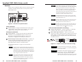
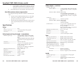
1024 x 768
1280 x 1024
1600 x 1200
700'
(215 m)
550'
(165 m)
500'
(150 m)
350'
(105 m)
300'
(90 m)
750'
(240 m)
650'
(200 m)
600'
(185 m)
450'
(135 m)
450'
(135 m)
N
1000'
(300 m)
N
>350'
(105 m)
>350'
(105 m)
>350'
(105 m)
>300'
(90 m)
>300'
(90 m)
800'
(245 m)
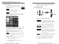
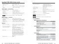
By default, the MTP T 15HD transmitter is configured to send
bi-level (normal) sync. For HDTV/component video applications,
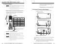
the transmitter can be configured to send tri-level sync (figure 1).
T
800 x 600
<300'
(90 m)
<300'
(90 m)
<300'
(90 m)
<250'
(75 m)
<250'
(75 m)
Pre-Peak Max. distance Max. distance
on
(high quality) (variable quality)
N
640 x 480
Pre-Peak
off
T
Video
format
Composite,
S-video,
Component
Setting the Transmitter Sync Jumper
(Component Video)
T
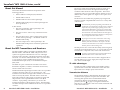
Recommended Pre-Peak switch positions and
transmission distances at 60 Hz
Tri-level
Sync
Normal
(Bi-level
Sync)
J6
Jumper Pins J6 Inside
Box
It is possible to exceed the recommended distance;
however, image quality may be reduced.
The transmitter and receiver are designed for and
perform best with Extron Enhanced Skew-Free A/V cable
terminated in accordance with the TIA/EIA T 568 A
wiring standard. CAT 5 cables are acceptable but less
preferable. Extron also recommends the use of preterminated and tested cables. Cables terminated on site
should be tested before use to ensure that they comply
with Category 5 specifications.
The recommendations shown in the table above apply for
a single transmitter and receiver and for a daisy chain.
For example, the maximum suggested range for
1024 x 768 video is 300' (90 m) with the Pre-Peak
switch off and 500’ (150 m) with the Pre-Peak switch on,
whether the system consists of one transmitter and one
receiver or a transmitter and three daisy-chained
receivers.
For daisy-chained units, the first receiver in the chain
must be at least 100' (30 m) from the transmitter when
the Pre-Peak switch is on.
For daisy-chained units, any receiver in the chain closer
than 350' (105 m) may experience some form of overpeaking when the Pre-Peak switch is on. An overpeaked
image may appear bloomed.
4
VersaTools® MTP 15HD A Series • Installation
Introduction
MT
15
T
P
A
HD
K
EA
E-P
PR
ON
UT
TP
OU
DIO
AU
OFF
OR
NIT
MO
R
WE
PO
V X
12 MA
.5A
UT
INP
Remove 4 screws and
lift the top straight up.
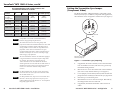
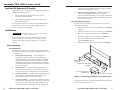
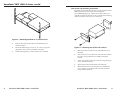
Figure 1 — Transmitter sync jumpering
1.
If applicable, disconnect all cables, remove the transmitter
from its installation location, and remove any previously
installed mounting brackets.
2.
Remove the two screws from either side of the transmitter
(four screws total) and lift off the top cover (figure 1).
3.
Locate jumper J6 on the main (bottom) board and shift the
jumper from the normal (N) to the tri-level sync (T) position.
4.
Place the top cover back into place.
5.
Reinstall the four screws removed in step 2. Reinstall any
mounting brackets that were removed.
6.
If applicable, reinstall the transmitter and reconnect all
cables.
® ®
VersaTools
VersaTools
MTP
MTP
15HD
15HD
A Series
A Series
• Configuration
• Installation
5