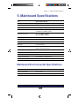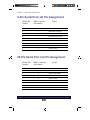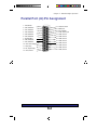
1
The COMPLETE GUIDE TO HIGH-PERFORMANCE COMPUTING WITH YOUR PANTERA COMPUTER User’s Guide Copyright 1995 ZEOS International, Ltd. All rights reserved ZEOS International, Ltd. shall not be held liable for technical or editorial omissions or errors made herein; nor for incidental or consequential damages resulting from furnishing, performance, or use of this material. This document contains proprietary information protected by copyright. No part of this document may be photocopied or reproduced by mechanical, electronic, or other means in any form without prior written permission of ZEOS International, Ltd. Trademark Acknowledgments Adaptec is the trademark of Adaptec, Inc. IBM, XT, AT, and OS/2 are registered trademarks of International Business Machines Corporation. UNIX is a trademark of AT&T Laboratories. Phoenix is the trademark of Phoenix Technologies Ltd. Quadtel is the trademark of Quadtel Corp., A Phoenix Technologies Ltd. Co. Intel, 486SX, DX, DX2, DX4, and Pentium are trademarks of Intel Corporation. XENIX, MS-DOS, GW-Basic, Windows, and Microsoft are trademarks of Microsoft Corporation. All other brand and product names are trademarks or registered trademarks of their respective companies. Limitation of remedies and liabilities: ZEOS’ entire liability and customers’ exclusive and sole remedy for damages from any cause whatsoever (including without limitation any nonperformance, misrepresentation, or breach of warranty) shall be limited to returning the products pursuant to the thirty (30) day satisfaction guarantee, or to repair or replace specific products or services that do not comply with the limited warranty given by ZEOS. Any products or services repaired or replaced by ZEOS pursuant to this paragraph shall be warranted as of the date of delivery in accordance with the terms and conditions herein for the duration of the one-year term of Limited Warranty given by ZEOS. In no event will ZEOS be liable for any damages caused, in whole or in part, by customer, or for any economic loss, physical injury, lost revenues, lost profits, lost savings or other indirect, incidental, special or consequential damages incurred by any person, even if ZEOS has been advised of the possibility of such damage for claims. Some states do not allow the exclusion or limitation of incidental or consequential damages for consumer products, and some states do not allow limitations on how long an implied warranty lasts, so the above limitations or exclusions may not apply to you. This warranty gives you specific legal rights, and you may also have other rights which vary from state to state. ZEOS provides no warranties whatsoever on software. 700-0195-01 CMAX 2 ZEOS Computer Systems One Year Limited Warranty All new ZEOS computer systems come with a One Year Limited Warranty which provides that the products ZEOS manufactures or assembles, other than items such as software, disks and related documentation, will remain in good working condition, free from defects in material and workmanship under normal use and service, for a period of one year from the date of shipment from ZEOS. This warranty is limited to the original purchaser and is not transferable. During this one year period, ZEOS will repair or replace, at its option, any defective product or parts at no additional charge to the customer, provided that the defective product or part is returned, shipment prepaid, to ZEOS. All replaced products and parts become the property of ZEOS. Replacement parts shall be similar new or serviceable used parts. This Limited Warranty does not extend to any products which have been damaged as a result of accident, misuse, abuse (such as incorrect voltages, power surges, improper or insufficient ventilation, failure to follow ZEOS’ provided operating instructions, “acts of God” or other situations beyond the control of ZEOS), or as the result of service or modification by anyone other than ZEOS. Non-ZEOS installed parts or components are not covered, nor is damage to ZEOS provided components covered as a result of their installation. This warranty does not cover work performed by others, all warranty work must be performed by ZEOS. 3 Contents 1. The Big Picture .......................................................................... 9 Desktop System At A Glance ................................................... 10 Tower System At A Glance ....................................................... 12 How to Open a Desktop Case .................................................. 14 How to Open a Tower Case ..................................................... 16 Inside a Desktop Computer ...................................................... 18 Inside a Tower Computer.......................................................... 19 2. The Mainboard......................................................................... 20 Mainboard Features ................................................................. 20 PCI Local Bus 32-Bit High Speed Expansion Slots................................ 21 Secondary Cache Subsystem ............................................................... 21 Continuous Full-Speed Processing ........................................................ 21 On-Board Peripherals ............................................................................ 22 Serial Ports ............................................................................................ 22 Parallel Port ........................................................................................... 23 PCI SCSI/ Ethernet Port ........................................................................ 24 Business Audio Ports ............................................................................. 25 Mainboard Diagram .................................................................. 26 Mainboard Connectors ............................................................. 27 Mainboard Jumpers .................................................................. 28 Jumper Settings ....................................................................... 29 Mainboard Jumpers Described ................................................. 30 FLASH1 ................................................................................................. 30 CLR1 ..................................................................................................... 30 CLK1 ...................................................................................................... 31 CACHE1 ................................................................................................ 31 3. Using SETUP ........................................................................... 32 Main Menu ............................................................................... 33 Main Menu Options .................................................................. 34 System Time .......................................................................................... 34 System Date .......................................................................................... 34 Daylight Savings .................................................................................... 34 Diskette Drive A: .................................................................................... 34 Diskette Drive B: .................................................................................... 34 4 IDE Adapters (Four Provided) ............................................................... 34 Video System ........................................................................................ 35 Memory Control ..................................................................................... 36 Memory Shadow .................................................................................... 37 Advanced Menu ....................................................................... 38 Large Disk Access Mode ....................................................................... 38 OS support for more than 64MB ........................................................... 38 Plug & Play O/S ..................................................................................... 38 Integrated Peripherals ........................................................................... 38 PCI Devices ........................................................................................... 41 Security Options ....................................................................... 42 Supervisor Password is ......................................................................... 42 User Password is ................................................................................... 42 Password on boot .................................................................................. 43 Diskette access ..................................................................................... 43 Fixed disk boot sector ........................................................................... 43 System backup reminder ....................................................................... 43 Virus check reminder ............................................................................. 43 Power Options.......................................................................... 44 Power Savings ....................................................................................... 44 Standby Timer Reset Events ................................................................. 44 Standby Break Events ........................................................................... 45 Standby Wakeup Events ....................................................................... 45 Exit Menu Options .................................................................... 45 4. Expanding Your System ......................................................... 46 Adding an Expansion Board ..................................................... 46 How Disk Drives Work.............................................................. 48 How a Floppy Drive Works ....................................................... 49 How an IDE Hard Drive Works ................................................. 50 How a CD-ROM Drive Works ................................................... 51 Adding System RAM ................................................................ 52 Installing SIMMs ....................................................................... 53 Adding System Cache Memory ................................................ 55 Installing a New CPU ............................................................... 57 5 5. Mainboard Specifications....................................................... 59 Mainboard Environmental Specifications .................................. 59 9-Pin Serial Port (J2) Pin Assignment ...................................... 60 25-Pin Serial Port (J3) Pin Assignment .................................... 60 Parallel Port (J4) Pin Assignment ............................................. 62 Handy Cheat Sheet ...................................................................... 64 Glossary ....................................................................................... 66 Index ............................................................................................. 68 6 FCC Compliance Statement For U.S. and Canadian Users Warning! Changes or modifications to this unit not expressly approved by the party responsible for compliance could void the user’s authority to operate the equipment. This equipment has been tested and found to comply with the limits for a Class B digital device, pursuant to Part 15, Subpart B of the FCC Rules. These limits are designed to provide reasonable protection against harmful interference in a residential installation. This equipment generates, uses and can radiate radio frequency energy and, if not installed and used in accordance with the instructions, may cause harmful interference to radio communications. However, there is no guarantee that interference will not occur in a particular installation. If this equipment does cause harmful interference to radio or television reception, which can be determined by turning the equipment on and off, the user is encouraged to try to correct the interference by one or more of the following measures. • Reorient or relocate the receiving antenna. • Increase the separation between the equipment and receiver. • Connect the equipment into an outlet on a circuit different from that to which the receiver is needed. • Consult the dealer or an experienced radio/TV technician for help. The connection of a non-shielded equipment interface cable to this equipment will invalidate the FCC Certification of this device and may cause interference levels which exceed the limits established by the FCC for this equipment. This equipment is a Class B digital apparatus which complies with the Radio Interference Regulations, C.R.C., c. 1374. Cet appareil numèrique de la classe B est conformè au Règlement sur le brouillage radioèlèctrique, C.R.C., ch. 1374. 7 Customer Assurance Program Thirty (30) Day Money-Back Guarantee on Most Products. Any product (except for software, software disks, related documentation and consumables) purchased from ZEOS may be returned within thirty days from the date it was shipped by ZEOS for a full refund of the purchase price excluding original shipping charges. Returned products must be in as new condition, in original packing, complete with all warranty cards, manuals, cables and other materials as originally shipped; not modified or damaged. Any returned product must be shipped prepaid and insured. Any return must carry a ZEOS Return Merchandise Authorization (RMA) number, obtained from ZEOS, on the outside of each carton. Returns without RMA numbers will not be accepted. After thirty days from shipment, all sales are final and credit or refunds will not be given. 8 Chapter 1 - The Big Picture 1. The Big Picture Welcome to the ZEOS User’s Guide! The User’s Guide works with the Getting Started manual to help keep your system running trouble free, year after year. This User’s Guide is divided into five chapters. Chapter 1, The Big Picture gives an overview of a typical desktop and tower system. It also shows the major components inside the computer case. Chapter 2, The Mainboard gives detailed information about your mainboard. Chapter 3, Using SETUP explains how to use the SETUP utility program to customize the built-in features of your system’s BIOS (Basic Input/Output System). Chapter 4, Expanding Your System shows how to add components and enhancements to your system. These include a video adapter card, a controller card, an internal modem, a floppy drive, an IDE hard drive, a CD-ROM drive, memory RAM SIMMs, system LEVEL 2 cache, and a new CPU. Chapter 5, Mainboard Specifications includes your mainboard specifications, environmental specifications, plus pin assignments for your serial and parallel ports. The Handy Cheat Sheet gives a short summary of some of the most needed or most forgotten commands. The Glossary gives short definitions of some common computer terms. 9 Chapter 1 - The Big Picture Desktop System At A Glance Brightness Power LED Contrast Hard Disk (HDD) LED Monitor Power Switch Reset Button Computer Power Switch (the “ON” button) Keyboard Lock Turbo Button (not used) Drive bays with CDROM drive and 3.5” Floppy Drive Turbo LED (not used) 10 Chapter 1 - The Big Picture AC Power Cable 110-220V Switch Mouse Cable Connector (9-pin Serial COMA) Video Connector (location varies with model) Cooling Fan Parallel Printer Port Connector (LPT1) AC Power Cable Keyboard Connector Secondary Serial Port (25-pin COMB) 11 Chapter 1 - The Big Picture Tower System At A Glance Turbo LED (not used) Turbo Button (not used) Reset Button Hard Disk (HDD) LED Power LED Computer Power Switch (the “ON” button) Keyboard Lock Drive bays with CD-ROM drive and 3.5” Floppy Drive Brightness Contrast Monitor Power Switch 12 Chapter 1 - The Big Picture Secondary Serial Port (25-pin COMB) Cooling Fan AC Power Cable Keyboard Connector Mouse Cable Connector (9-pin Serial COMA) AC Power Cable Parallel Printer Port Connector (LPT1) Video Connector (location varies with model) 13 Chapter 1 - The Big Picture How to Open a Desktop Case Caution! Whenever you open the case or work inside the computer there is danger of static electric shock. These shocks can permanently damage your equipment. Always ground yourself by touching the system cabinet before touching any internal component. We strongly recommend using an antistatic wrist strap attached to cabinet ground. To open a desktop case: 1. Turn off the monitor and system unit power. Unplug the AC power cables and disconnect any other cables attached to the back of the system unit. 2. Remove the plastic bezel from the back of the case by pulling it away from the case. 3. Unscrew the five mounting screws at the back of the case that hold the case cover to the system unit chassis. 4. Slide the case cover back and up. Be careful not to snag any cables or connectors inside the case. 5. Set the case cover aside while you work on your system. 6. When through, reattach the case cover, screws, bezel, and cables in the reverse order. The figures opposite show the plastic bezel, screw locations, and how to remove a desktop PC’s cover. 14 Chapter 1 - The Big Picture Mounting Screws Cover Chassis Plastic Bezel 15 Chapter 1 - The Big Picture How to Open a Tower Case Caution! Whenever you open the case or work inside the computer there is danger of static electric shock. These shocks can permanently damage your equipment. Always ground yourself by touching the system cabinet before touching any internal component. We strongly recommend using an antistatic wrist strap attached to cabinet ground. Opening a tower case is almost identical to opening a desktop case. To open a tower case: 1. Turn off the monitor and system unit power. Unplug the AC power cables and disconnect any other cables attached to the back of the system unit. 2. Remove the plastic bezel from the rear of the case by pulling it away from the case. 3. Unscrew the six mounting screws at the back of the case that hold the case cover to the system unit chassis. 4. Slide the case cover back and up, taking care not to snag any cables or connectors inside. 5. Set the case cover aside while you work on your system. 6. Afterwards, reattach the case cover, screws, bezel, and cables in the reverse order. The figures opposite show the plastic bezel, screw locations, and cover motion for a tower case. 16 Chapter 1 - The Big Picture Mounting Screws Cover Plastic Bezel Chassis 17 Chapter 1 - The Big Picture Inside a Desktop Computer Expansion Slots Power Supply Hard Disk Drive Mainboard CPU Front of Computer Floppy Drives, CD-ROM Drives, and Tape Backup Units The mainboard is the large circuit board at the bottom of the chassis. It is the heart of your system. All of the other components inside the case work for the mainboard. The power supply delivers electricity to the mainboard. The disk drives, keyboard connectors, and other parts of the system unit bring information to and from the mainboard. The figure above shows some of the most common components inside the computer. 18 Chapter 1 - The Big Picture Inside a Tower Computer Floppy Drives, CD-ROM Drives, and Tape Backup Units Power Supply Front of Computer Expansion Slots Hard Disk Drive CPU Mainboard Tower systems have the same components as desktop systems. The figure above shows the mainboard and typical components inside a Tower case. 19 Chapter 2 - The Mainboard 2. The Mainboard The mainboard is the largest circuit board in the computer. It contains the CPU (Central Processing Unit), the Level 2 cache, expansion slots, ports and connectors for other components, and the system’s main memory, or RAM (Random Access Memory). Mainboard Features Standard Features: • Intel Pentium (aka P54C) running at 75, 90, or 100 MHz • Optional 256K or 512K Level 2 system cache, write-back, directmapped • Integrated on-board floppy drive controller • Two on-board IDE hard drive interface ports supporting up to 4 IDE devices (both are PCI local bus) • Bi-directional Parallel Port (configurable through software) • Two RS232, 16550 high-speed serial ports • RAM Configurations: 2, 4, 6, 8, 10,12, 16, 32, 64, 128, 192, 384MB, etc. (Banks must hold identical pairs) • 384Mb maximum RAM capacity • Flash BIOS, relocatable to system RAM to boost performance • Five 16-bit ISA expansion slots • Three 32-bit PCI local bus expansion slots • Clock/calendar with on-board battery backup • Energy saving, low power “sleep” mode Factory Installed Options: • AMD SCSI host adapter socket on PCI bus • AMD network controller on PCI bus 20 Chapter 2- The Mainboard PCI Local Bus 32-Bit High Speed Expansion Slots The three PCI local bus, high speed expansion slots move information at up to 132 MB/s. This offers a high performance, 32-bit interface to support local bus peripherals such as video cards, LAN adapters and hard disk drives. Secondary Cache Subsystem The secondary (Level 2) cache subsystem enhances the performance of the CPU. The onboard cache controller allows cache memory to provide an ultra high-speed, 12-15-nanosecond buffer between the CPU and conventional (50, 60, or 70ns) RAM. Your system can accommodate three cache configurations: 0K, 256K, or 512K of Level 2 cache. The single cache slot (labelled CACHE) is located next to the CPU. Continuous Full-Speed Processing Pantera systems now run continuously at maximum speed, eliminating Turbo Mode. Because of this, the Turbo button and Turbo LED are not used on Pantera systems. 21 Chapter 2 - The Mainboard On-Board Peripherals Your mainboard has all of the standard peripheral interfaces and many extras built in. This eliminates the need for many peripheral expansion cards and greatly enhances system reliability. Integrated on-board peripherals include: • Two serial ports (16550 UART) • Parallel port (bi-directional, assigned through SETUP) • Floppy drive controller (handles floppy drives up to 2.88Mb) • Two PCI local bus IDE hard drive controller ports, each capable of controlling two hard drives Factory installed options: • SCSI port (supports both SCSI-1 and -2 type devices) • Ethernet port • Business audio with speaker output jack, alternate internal speaker output, and microphone input jack Serial Ports Your mainboard has two RS-232C asynchronous serial ports, which are usually referred to as COM1 or COMA (9-pin) and COM2 or COMB (25pin) ports. The serial ports are used to attach mice, serial printers, modems, or other serial peripheral devices. Both serial ports are 16550 UART compatible for higher data transfer rates. You can install up to two additional serial ports (COM3 and COM4) simultaneously in your system. However, because MS-DOS does not manage more than two COM ports simultaneously very well, you shouldn’t attempt to use more than two COM ports at the same time. Specifically, don’t try to use COM1 and COM3 at the same time, or COM2 and COM4 at the same time. 22 Chapter 2 - The Mainboard Parallel Port The 25-pin Centronics parallel port is often called the printer port because it is usually used for printers. However, devices that use this speedy parallel interface are becoming more common. Your Pantera’s parallel port is also Bi-directional, allowing data to flow to and from an external device at the same time. 23 Chapter 2 - The Mainboard PCI SCSI/ Ethernet Port The optional on-board SCSI (host adapter allows you to connect and control up to seven peripheral devices such as SCSI-compatible disk drives, tape backup units, communications devices, and CD-ROM drives. The SCSI port is a parallel, multitasking interface which supports both SCSI-1 and SCSI-2 devices. The SCSI port is configured from the system SETUP program. For SCSI system setup parameters, refer to the SCSI Control Menu in Using SETUP. The SCSI host adapter socket can also accept an Ethernet LAN controller chip allowing you to make direct Ethernet LAN connections for high speed local area network communications. Note: The on-board SCSI and LAN options are factory installed options only. The onboard SCSI and LAN option can only be upgraded at the time of purchase. 24 Chapter 2 - The Mainboard Business Audio Ports The on-board business audio adapter chip (if installed) allows you to use a built-in external speaker jack and microphone input jack for fullfeatured audio support of many popular software packages. The external speaker jack and microphone input jack are mounted on a bracket at the back of the system unit. Note: If you purchased your system with a sound card, you won’t have the business audio feature. 25 Chapter 2 - The Mainboard Main 9-pin Serial Port COMA Power Supply J2 16 bit ISA Connectors Expansion PS1 Slots Mainboard Diagram 16 bit ISA Expansion Slots BIOS Chip 32-bit PCI Expansion Slots Keyboard Connector J1 25-pin Serial Port COMB J3 Parallel Port J4 slot 8 slot 7 slot 6 slot 2 slot 1 slot 5 slot 4 slot 3 Floppy Header J5 System Battery PCI Configuration Header J6 PS2 Secondary Power Supply Connector Primary CPU U26 Secondary IDE Hard Drive Header J8 SIMM Sockets for System RAM 10Base2 Adapter Header J9 CPU Clock Jumper CLK1 Secondary CPU (future) U21 Primary IDE Hard Drive Header J7 SCSI Device Header J11 CACHE1 Jumper Level 2 SIMM Socket (System Cache) LAN/SCSI Chip Socket (optional) U27 Mute LED, Mute HDD LED & PC Power-On LED & LAN/SCSI Chip Clock Input (not used) & Speaker Header Keyboard Lock J13 Oscillator Y3 Reset Input (J15) J14 26 Audio Port Header AP4 10BaseT Adapter Header J10 10BaseT Filter Chip Socket FD1 PC Speaker Header AJ1 Microphone Input Jack AJ2 Speaker Output Jack AJ3 Chapter 2 - The Mainboard Mainboard Connectors Connectors and headers are used to attach devices to the mainboard. Attached devices can be internal (e.g., hard disk indicator lights), or external (e.g., serial and parallel ports). The most commonly used connectors are shown in the Mainboard Diagram. The table below provides a brief summary. Table 1. - Mainboard Connectors Connector ID Description J1 Keyboard connector PS1 Main power supply header PS2 PCI 3.3 volt power supply header J2 COMA: communications port A (DB9) J3 COMB: communications port B (DB25) J4 LPT1: Parallel “printer” port header J5 Floppy disk drive header J6 PCI Configuration header J7 Primary IDE hard drive header (PCI local bus) J8 Secondary IDE hard drive header (PCI local bus) J9 10Base2 (BNC) adapter header J10 10BaseT (RJ45) adapter header J11 SCSI device header J13 KBDLOCK: Keyboard Lock input J14 SPEAKER output, HDD LED output J15 RESET switch input, Mute LED (not used), Business Audio Mute (not used) 27 Chapter 2 - The Mainboard Mainboard Jumpers 12345678 12345678 12345678 12345678 12345678 12345678 12345678 12345678 12345678 12345678 12345678 12345678 12345678 12345678 12345678 12345678 12345678 12345678 12345678 12345678 12345678 12345678 12345678 12345678 12345678 12345678 12345678 12345678 12345678 12345678 12345678 12345678 12345678 12345678 12345678 12345678 12345678 12345678 12345678 12345678 12345678 12345678 12345678 12345678 12345678 12345678 12345678 12345678 12345678 12345678 12345678 12345678 12345678 12345678 12345678 12345678 12345678 12345678 12345678 12345678 12345678 12345678 12345678 12345678 12345678 12345678 1234567 1234567 1234567 1234567 1234567 1234567 1234567 1234567 1234567 1234567 1234567 28 Chapter 2 - The Mainboard Jumper Settings Note: Do not change this jumper. 29 Chapter 2 - The Mainboard Mainboard Jumpers Described Jumpers are small groups of pins that can be connected or disconnected with jumper caps. To connect a jumper, carefully place the jumper cap over the pins you wish to connect, then gently press down. The mainboard uses six jumpers, allowing great system flexibility. However, most system settings are stored in battery-backed CMOS (Complimentary Metal-Oxide Semiconductor) memory. You can use the BIOS SETUP program to change settings stored in the CMOS. Other mainboards use jumpers to configure upgrade options and parameters on the mainboard. Pantera mainboards use the SETUP program and the FLASH programming utility instead, making BIOS changes and upgrades without removing the BIOS chip. FLASH1 The FLASH1 jumper allows or disallows reprogramming of the FLASH BIOS with the FLASH utility program. The factory default (NORMAL) setting allows you to reprogram the BIOS with the FLASH utility. CLR1 The CLR1 jumper holds or resets the factory default BIOS settings stored in the CMOS (Complimentary Metal-Oxide Semiconductor) BIOS chip. You should not clear the CMOS memory unless it becomes corrupted and cannot be reprogrammed with the SETUP program, which also can reset the factory default BIOS settings. To clear the CMOS memory, turn off system power, then momentarily place the jumper in the CLEAR position, then return the jumper to the NORMAL position. Your system will not operate with the jumper in the CLEAR position, so be sure to return the CLR1 jumper to the NORMAL position. (continued next page) 30 Chapter 2 - The Mainboard Mainboard Jumpers Described (continued) CLK1 The CLK1 jumper sets the speed of the system clock. It will be set correctly to work with your system, so don’t change this jumper unless you change CPUs. Pins Jumpered CPU Clock Speed (MHz)Bus Clock Speed (MHz) 1 and 2 100 66 2 and 3 90 60 1, 2 and 3 75 50 See the diagram, Mainboard Jumpers, for the location of these jumpers. CACHE1 A fast CPU operates more efficiently when it has a buffer of ultrafast RAM between itself and system RAM. The CACHE1 jumper configures how Level 2 cache is used by your system. 256K to 512K of cache can be added by inserting a standard cache SIMM. The cache controller is integrated into the system chipset. CPU Pipelining Increases data throughput by allowing the CPU to start the next machine cycle before it finishes processing the current one. Burst Cache Module During a single machine cycle, a bursting CPU generates a beginning address and a quantity of bytes for the cache to expect. Then the CPU transfers that quantity of bytes as a single package, without needing to generate any intermediate addresses. Asynchronous Cache Module An asynchronous cache can generate wait states that tell the CPU to delay transferring information until valid data is ready to be transferred to or from the cache. 31 Chapter 3 - Using SETUP 3. Using SETUP The SETUP utility program allows you to customize the power-on initialization parameters of your computer’s BIOS (Basic Input/Output System). You may need to use the SETUP program if you add components to your system. To run the BIOS SETUP program, press F2 during system boot. Once inside SETUP, you can reach different sections by pressing the right/left arrow keys on your keyboard. Inside each section, you can go into a subsection (indicated by a right-pointing triangle on the left side of the screen) by moving to it with the up/down arrow keys, then pressing the Enter key. Setup’s five sections are Main, Advanced, Security, Power, and Exit. Each section contains topics you can view or adjust to suit your system’s needs. SETUP allows you to customize various system parameters, although our technicians optimize them for your system as shipped. If you inadvertently change BIOS values that cause your system to malfunction, you can simply reload the original factory default settings from ROM by entering SETUP, then pressing the F9 key. Otherwise, you can load the most recently saved settings from battery backed CMOS by pressing F10. Within SETUP, pressing F1 toggles the General Help window, while the right-hand panel describes the function of the currently highlighted topic. To change your BIOS settings, first use the arrow keys to highlight the desired topic, then press the space bar or the <+> or <->key on the numeric keypad to rotate through the available options. Note: only an item whose label is surrounded by [square brackets] may be changed; values not in brackets can only be viewed. Once you’ve finished customizing your BIOS settings, press the Esc key a couple times to reach the Exit menu. There you can decide if you really want to keep your changes, if you’d prefer to return to the factory defaults, or if you want to go back to using your previously saved values. In any case, remember you can always change the BIOS settings again next time you boot up. 32 Chapter 3 - Using SETUP Main Menu Your system’s BIOS settings were configured at the factory to maximize performance with the options you ordered. Generally, you need to run SETUP only if you install a new or different hard drive, if the on-board battery fails, or if you otherwise add to or change your basic hardware. SETUP’s Main Menu allows you to view and configure several basic parameters, including system time, date, and daylight savings, Diskette A and B, system memory (RAM) timing, memory shadowing, boot sequence options, and video system type. The Main Menu lets you configure four PCI local bus IDE devices: • IDE Adapter 0 Master (Drive letter, capacity in megabytes) • IDE Adapter 0 Slave (Drive letter, capacity in megabytes) • IDE Adapter 1 Master (Drive letter, capacity in megabytes) • IDE Adapter 1 Slave (Drive letter, capacity in megabytes) Each of the four IDE Adapter subsections lets you view and customize the settings for a separate PCI local bus IDE device attached directly to you mainboard. The subsections are described on the following pages. SETUP’s Main Menu also contains subsections for Memory Control, Memory Shadow, and Boot Sequence. Finally, System Memory and Extended Memory are displayed. At the very bottom is a chart showing how to navigate and change values in SETUP. 33 Chapter 3 - Using SETUP Main Menu Options System Time Sets the real-time clock, using a 24-hour format. During the power-up sequence, the real time is read and saved in memory for use by the operating system. After boot up, the operating system updates the system time. System Date Sets the real-time date for month, day, and year. During the power-up sequence, this information is read and saved in memory for use by the operating system to determine the current date. After completing the power-up sequence, the operating system updates the current date. Daylight Savings Adjusts system clock for daylight savings time. Default: Enabled. Diskette Drive A: Specifies the size and capacity of the floppy-disk drive installed as drive A. Options are: 360K, 720K, 1.2M, 1.44M, and 2.88M. Diskette Drive B: Specifies the size and capacity of the floppy-disk drive installed as drive B. IDE Adapters (Four Provided) Each of the four IDE Adapter subsections allows you to view and change configurations of the IDE devices attached to your on-board IDE Hard Drive connectors, J7 and J8. The IDE Adapter subsections list the IDE devices that are currently installed. Your Primary hard drive (J7) is listed as IDE Adapter 0 Master. You can attach a second hard drive to the same cable as IDE Adapter 0 Slave, then two more devices on the Secondary connector (J8) as IDE Adapter 1 Master, or IDE Adapter 1 Slave. The following page describes the contents of each IDE Adapter subsection. Note: If you attach two drives to a single drive cable, it doesn’t matter whether or not the Master drive is connected to the end connector. Just be sure that one drive is configured as Master and the other drive is configured as Slave. 34 Chapter 3 - Using SETUP Autotype Fixed Disk This utility detects and configures your IDE Adapter, if the device conforms to ANSI technical specifications. ZEOS drives are configured at the factory, so to add a hard drive you just run Autotype. If Autotype is successful, it will identify your hard drive type and display the drive parameters. Otherwise, you can select one of the established drive type numbers from the Type list, or select Type USER to set Cylinders, Heads, Sectors/Track and Write Precomp yourself (according to the information supplied by the device’s manufacturer). Note: Don’t alter drive parameters unless you change or add a hard drive. Multi-Sector Transfer Determines the number of sectors per block for multiple sector transfers. Options are Disabled, 2, 4, 8, and 16. Older hard drives (and even some newer drives) will not work properly if the number of sectors is set too high. Default: 16. Note: Before adding a new hard drive or formatting one from Zeos, first disable MultiSector Transfers, then format the drive, then run FDISK. Later, you can enable Multi-Sector Tranfers again. Write Precomp Write Precompensation. In older hard drives, this setting tells the drive to apply a stronger magnetic field to inner tracks of the disk to compensate for magnetic drift. Your hard disk manufacturer’s documentation should tell you if your drive requires this setting. Default: None (Disabled). LBA Mode Control Enables or disables Logical Block Addressing, allowing you to use large IDE hard drives. This must be enabled for IDE hard drives greater than 528 MB. Default: Set at the factory. Video System This option sets the video type. It can be set to Monochrome, CGA 80 x 25 (80 column Color Graphics), or EGA/VGA (Enhanced/Video Graphics Adapter). Default: EGA/VGA. 35 Chapter 3 - Using SETUP Memory Control The Memory Control subsection lets you view and change DRAM (system RAM) Timing, enable/disable the L2 (Level 2) External Cache, and determine which shadowed upper memory regions (in addition to system and video) are allowed to be cached in a superfast (12-15ns) 256K or 512K SIMM. DRAM Timing Sets the upper limit for DRAM (system RAM) speed to 50, 60, or 70ns (nanoseconds). DRAM Timing must be set to match the speed of the slowest SIMM in your memory slots. Default: 70ns. External Cache Allows you to enable/disable the L2 (Level 2) External Cache feature. If the special Level 2 cache SIMM is present, it offers an ultrafast, 12- to 15-nanosecond buffer between your CPU and regular (50-70ns) system RAM. Normally L2 cache speeds up your system, but because some software has problems with L2 caching, you may (rarely) need to disable the External Cache. Default: Enabled. Cache Memory Regions Allows you to choose which specific shadowed BIOS memory regions (in addition to System code and Video code) will be cached. Regions are identified by hexadecimal (base 16) addresses. Default: All specific regions Disabled. 36 Chapter 3 - Using SETUP Memory Shadow BIOS shadowing copies data from portions of the computer’s slower ROM (Read-Only Memory) chips into much faster DRAM (system RAM) chips in system memory. This data can then be read more quickly by the CPU, so system performance improves. The Memory Shadow subsection lets you make certain regions of your upper memory (other than that reserved for basic system and video) available for BIOS shadowing. System Shadow This setting is not adjustable. System shadow is always Enabled. Video Shadow Enables/disables copying of the video BIOS into RAM. Shadowing the video BIOS code improves video performance. Default: Enabled. Shadow Memory Regions Allows additional specific memory regions (other than System and Video) to be shadowed in upper RAM memory. When enabled, any ROM data located in the specified region will be copied to shadow RAM when you boot up. Regions are identified by hexadecimal (base 16) addresses. Default: All specific regions Disabled. Boot Sequence Determines what drive the system checks first for an operating system. Choices are A: then C:, C: then A:, and C: only. Default: A: then C:. 37 Chapter 3 - Using SETUP Advanced Menu Warning! Setting these items incorrectly could cause your system to malfunction. Never needlessly change from the defaults. The Advanced Menu offers the following options: Large Disk Access Mode Lets you set your system to expect a large DOS hard disk, or some Other type of hard disk, such as expected by UNIX or Novell Netware. Default: DOS. OS support for more than 64MB This option allows support for more than 64MB of memory with operating systems other than DOS, such as OS/2 and Windows NT. On systems with more than 64MB of memory, set to disable for DOS and Windows, Enable for OS/2 and Windows NT. Default: Disabled. Plug & Play O/S Enables/disables peripheral add-on features for computers with Plug & Play operating systems. Default: No. Integrated Peripherals Lets you configure your serial and parallel ports, as well as your on-board floppy disk controller, your on-board IDE controller, your audio device (if present), and your PC’s speaker volume. The following list describes each of these parameters. (more settings, next page) 38 Chapter 3 - Using SETUP Advanced Menu (continued) 1st COM Port When 1st COM Port (COM A) is set to Auto, the system will automatically set the interrupt and IRQ for that port. Otherwise this option allows you to choose (from a list) the interrupt and I/O address of the 9-pin serial port. Default: Auto. 2nd COM Port When 2nd COM Port (COM B) is set to Auto, the system will automatically set the interrupt and IRQ for that port. Otherwise this option allows you to choose (from a list) the interrupt and I/O address of the 25-pin serial port. Default: Auto. LPT Port Sets the parallel port designation. This allows you to specify the parallel port address and IRQ, which otherwise are factory set. Default: Auto. LPT Mode Allows you to set the parallel port communication mode to match the capabilities of your parallel port device. Settings: Unidirectional, Bidirectional or Enhanced. Default: Unidirectional. Floppy Disk Controller Configures the on-board floppy disk controller to Primary, Secondary, or Disabled. Default: Primary. 39 Chapter 3 - Using SETUP IDE Controller Enables/disables the on-board IDE controller, which controls up to four PCI local bus devices. Default: Enabled. Audio device Disables or sets the audio DMA (Direct Memory Access) channel and IRQ for the on-board audio device. Default: set at factory. PC Speaker volume Sets PC speaker to low, medium or high volume, or disables it. Default: Medium. 40 Chapter 3 - Using SETUP PCI Devices The PCI (Peripheral Component Interconnect) Devices subsection allows you to enable or disable the integrated SCSI and LAN options. Enable On-board SCSI Enables/disables the built-in SCSI port, if present. Default: set at factory. On-board Ethernet Enables/disables the on-board AMD Ethernet controller, if present. Default: set at factory. 41 Chapter 3 - Using SETUP Security Options The Security Menu allows you to password-protect system access, a way of safeguarding information. When passwords are enabled, users must type the proper password to access the protected part of the system. Note: 1. It’s easy to forget a password, so we strongly recommend writing down your passwords and storing them in a secure place. 2. If you type the User password on entering SETUP, you cannot change the Supervisor Password or Diskette Access settings. Warning! If you forget the password, your system will not operate. You will have to completely clear the CMOS memory and reenter your entire system configuration. Write down your password and store it in a safe place. The following security items are available: • Set Supervisor Password • Set User Password • Password on Boot • Diskette Access • Fixed disk boot sector • System Backup Reminder • Virus Check Reminder Supervisor Password is Allows you to enter a system supervisor password. This password controls access to all features of your system. User Password is Accessible only after Supervisor Password is enabled, this allows you to enter a system user password. You can’t use the User Password to alter the Supervisor Password in SETUP. 42 Chapter 3 - Using SETUP Password on boot When enabled, the system asks you for a password on boot. The system will boot only after the correct supervisor or user password is entered. Default: Disabled. Diskette access Active only when a Supervisor password is enabled, this specifies which level of password (Supervisor or User) is required on bootup to use the floppy disk drives. This can prevent unauthorized transfer of data. Default: Supervisor. Note: All diskette drive access can be denied (including system diskettes) by 1) setting a Supervisor password, 2) setting Password on Boot to Disabled, then 3) setting Diskette Access to Supervisor. Fixed disk boot sector When enabled, write protects the boot sector on your hard drive to protect against viruses. Default: Disabled. System backup reminder When enabled, this periodically displays a boot reminder message to back up your system. Options: Daily, Weekly, Monthly, Disabled. Default: Disabled. Virus check reminder When enabled, this periodically displays a boot reminder message to scan for viruses. Options: Daily, Weekly, Monthly, Disabled. Default: Disabled. 43 Chapter 3 - Using SETUP Power Options The Power menu lets you tell your system to enter a low-power Standby mode when it is idle for a specified time. Standby minimizes your system’s energy consumption while allowing you to resume work within moments. Power Savings Lets you choose the how to conserve power used by your CPU, your fixed disk drives, and your monitor. Settings: Customize (default), Maximum, Medium, Minimum, and Disabled. This allows you to opt for one of three preset configurations, customize the Standby settings yourself, or disable power savings altogether. The list below describes what each setting controls: • Standby Timeout controls how long (1 minute to 4 hours, or Disabled) your system must be idle before it enters Standby mode. • Standby CPU Speed dictates the level of CPU activity (Max, High, Medium, Low) during Standby. • Fixed Disk Timeout controls how long (1-16 minutes, or Disabled) an idle system waits before stopping the hard disk motor. • CRT can be set to OFF in Standby or always ON. Standby Timer Reset Events When enabled, these two settings prevent the system from entering Standby mode while you’re using the keyboard or the mouse. Keyboard Keeps system from entering Standby mode while you’re using the keyboard. Default: Enabled. Mouse Keeps system from entering Standby mode while you’re using the mouse. Default: COM1 (IRQ4). 44 Chapter 3 - Using SETUP Standby Break Events When set to Auto, this enables the system to resume full speed operation for as long as the specified IRQ is active. For example, this would allow you to “wake up” a remote computer via its modem, which uses an IRQ. You can set this parameter for 16 hardware IRQs, from IRQ0 to IRQ15. Default: All IRQs set to Auto. Standby Wakeup Events When enabled, these return the system to full speed when you begin using the keyboard or the mouse. It takes about six seconds for the CPU and the monitor to wake up, and a few moments for the hard drive to resume full speed from a standstill. Keyboard Returns the system to full speed when you begin using the keyboard. Default: Enabled. Mouse Returns the system to full speed when you begin using the mouse. Default: COM1 (IRQ4). Exit Menu Options Offers Exit and Save options for the SETUP program. 45 Chapter 4 - Expanding Your System 4. Expanding Your System Adding an Expansion Board The five ISA and three PCI expansion slots on your mainboard are designed to accept a wide variety of add-on cards (many available from ZEOS). Scanners, tape backup units, video capture devices, and many other devices come on expansion cards, which communicate with the CPU via standard expansion slots. Often, adding these components is as easy as opening the case, slipping the new card into an empty slot, then connecting the external component (if there is one) to the card. To add an expansion board: 1. Turn off the monitor and system unit power, then unplug the AC power cords from the wall outlet. 2. Open the system unit case (see How to Open a Desktop Case, earlier). 3. Find an empty expansion slot or, if you are replacing an expansion card already in your system (such as when upgrading your video card), locate the old card. 4. Unscrew the mounting screw and remove the blank bracket by sliding it up. If you are removing an old expansion card, carefully lift it straight up (sometimes you have to wiggle it a little). 5. Set any jumpers or switches on the new card. See the card’s documentation for the correct jumper settings. 6. Slide the new card into the slot. Press down firmly, so the edge connector slides completely into the slot. 7. Tighten the mounting screw. (more steps, next page) 46 Chapter 4 - Expanding Your System How to Add an Expansion Board (continued) Mounting Screw Expansion Slot 8. Connect any internal cables to the expansion card. 9. Close the computer case, and turn on the power. Many expansion cards require you to run diagnostic or installation software before the new board will work properly. Your expansion card’s installation manual should have detailed instructions. 47 Chapter 4 - Expanding Your System How Disk Drives Work There are three main types of disks for storing files - floppy, hard, and compact disks. Floppy disks are small, relatively slow, portable disks. Most people use floppy disks to transfer files or install new programs onto their hard drives. Floppy disks fit into the floppy disk drives mounted in your system unit. Although there are some combination drives, most floppy disk drives are designed to hold only one size of disk. Hard, or fixed disks, are permanently mounted inside your system unit case. They are very fast, hold a lot of files, and are not removable without disassembling your system. Compact disks fit into CD-ROM drives. Compact disks can store very large amounts of information. Floppy, hard, and CD-ROM disk drives all fit into the drive bays in your system unit. This chapter shows how some of the most common drives connect to the mainboard. Most drives have two connections - a power connection and a data connection. For detailed installation and configuration information, always check the disk drive’s documentation. 48 Chapter 4 - Expanding Your System How a Floppy Drive Works Floppy drives have two primary connectors, a ribbon cable called the data cable, and a power connection to the power supply. The ribbon cable connects the back of the floppy drive with the floppy controller port J5 on the mainboard. Data ribbon cables often have two connectors. If you have more than one floppy drive on your system, they often share the same ribbon cable. The data cable also has a red stripe. Whenever connecting or disconnecting the ribbon cable, be sure to attach the cable connectors so the red stripe is pointing toward pin 1 of the connector. Pin 1 is often labelled with a small triangle or filled in corner. Floppy Drive Primary Floppy Drive Connector DC Power from Power Supply Second Floppy Drive Connector Red Stripe (Pin 1) Floppy Drive Ribbon Data Cable Pin 1 Mark on Cable Connector Red Stripe (Pin 1) Pin 1 notch on mainboard connector Mainboard 49 Floppy Drive Cable Connector Chapter 4 - Expanding Your System How an IDE Hard Drive Works IDE (Integrated Drive Electronics) hard drives are the most common hard drives and are the most likely to be installed on your system. IDE devices have most of the electronics or “smarts” built into the drive, rather than installed on a separate controller card or on the motherboard. IDE hard drives have two main connections – a ribbon cable called the data cable and a power connection to the power supply. The ribbon cable attaches to the back of the drive and connects to the IDE controller port J7 or J8 on the mainboard. Whenever connecting or disconnecting the ribbon cable, be sure to attach the data cable so the red stripe points toward pin 1 on the connector. Most drives also have configuration jumpers at the back of the drive for setting drive identification and resistors. See your hard drive user’s guide for complete information. Keyboard Connector J1 Parallel Port J4 Floppy Connector J5 Red Stripe (pin 1) Primary IDE Hard Drive Header J7 System RAM SIMM Sockets Secondary IDE Hard Drive Header J8 50 Front of Computer Chapter 4 - Expanding Your System How a CD-ROM Drive Works CD-ROM drives read information from compact discs, or CDs. The “ROM” in CD-ROM stands for Read Only Memory. Compact discs are read-only--you can read information from them, but cannot add new files or information onto them as you can do with a floppy disk or hard disk. Despite their limitations, CDs have some distinct advantages. CDs can store large amounts of information--one compact disk can store as much information as 500 floppy disks. With the right software, you can even listen to music on your CD-ROM drive. There are many types of CD-ROM drives. Most have three primary connectors, a power connector, a data cable connector, and an audio connector. The power connector is just like the DC power connector on floppy drives and hard disk drives. It accepts DC power from the computer’s internal power supply. The data cable is a flat ribbon cable that connects the drive with some type of controller. Some drives use a dedicated controller card inserted into one of the expansion slots on the mainboard. Your IDE CD-ROM drive connects to the 16-bit IDE controller port on the mainboard (J8) or to an IDE controller card inserted into one of the expansion slots. Still other drives use a CD-ROM controller port mounted on a sound card in one of the expansion slots. Most CD-ROM drives also have an audio connector where you can connect headphones or computer speakers. If your system has a sound card and speakers installed, the CD-ROM drive’s audio connector probably can be connected to the sound card. For detailed information about your CD-ROM drive, check the manufacturer’s documentation. 51 Chapter 4 - Expanding Your System Adding System RAM System memory is often called RAM or Random Access Memory. RAM is the “thinking space” available to your applications. Usually, the more system RAM you have, the faster your system will run. Many software applications simply run much faster and more efficiently when more RAM is available. You add RAM by inserting Single In-line Memory Modules (SIMMs) into SIMM sockets on the mainboard. Your computer’s mainboard will hold up to six SIMMs of 32-bit RAM. Slots must be filled in sequence from 0A to 2B. You must have identical pairs of SIMMs in each bank, but different banks can support various capacities and speeds. The mainboard will support up to 384Mb of RAM. Note: SIMMs MUST ALWAYS BE INSTALLED IN SEQUENCE FROM BANK 0A TO BANK 2B, AND WITHIN THE SAME BANK, THEY MUST BE THE SAME SPEEDS AND CAPACITIES. Memory Size RAM Configurations SIMMs Used Memory Scheme 2MB two 1MB Page 4MB two 2MB Page/Interleaved 8MB two 4MB Page/Interleaved 10MB two 4MB, two 1MB Page/Interleaved 12MB six 2MB Page/Interleaved 16MB four 4MB Page/Interleaved 24MB six 4MB Page/Interleaved 32MB four 8MB Page/Interleaved 64MB four 16MB Page/Interleaved 128MB four 32MB Page/Interleaved 256MB four 64MB Page/Interleaved 384MB six 64MB Page/Interleaved Note: This is just a small sample of possible RAM configurations. 52 Chapter 4 - Expanding Your System Installing SIMMs When installing SIMMs, use 70ns or faster memory chips for maximum system performance. Different speed SIMMs may be mixed, but only if you put them different banks. In addition, always set the CPU/DRAM Speed option in SETUP to match the slowest SIMM. Note that with SIMMs, larger numbers mean that more time is used to access information (a 70ns SIMM is slower than a 60ns SIMM). For best results, use SIMMs from the same manufacturer. Caution! Static electric shocks can permanently damage your equipment. Always ground yourself by touching the metal part of the computer case before beginning the following procedure. We strongly recommend using an antistatic wrist strap attached to the case ground. To Install SIMMs: 1. Remove system cover (see How to Open a Desktop Case, earlier). 2. Remove any SIMMs you are replacing with new SIMMs by gently pulling the metal socket clips away from the SIMM to release the SIMM from the socket. Hold them out while you are tilting the SIMM away from the metal clips. Carefully lift the SIMM up and out. Caution! Never use force to remove the module out of the socket. Failure to properly release the retainer clips may break the socket, causing expensive damage which is not covered by your warranty. 3. Grasping a new SIMM by the edge, remove it from the antistatic bag. 4. Insert the bottom edge into the socket slot. Press down firmly on the SIMM while maintaining the proper angle of insertion. (more steps, next page) 53 Chapter 4 - Expanding Your System Installing SIMMs (continued) Retaining clip Retaining Clip Inserting a SIMM 5. Ensure the SIMM seats correctly. If not, remove and repeat Step 4. 6. Gently push the top edge toward the retainer clips until the clips snap into place. 7. Reinstall system cover. After completing the installation, your ROM BIOS will determine the amount of memory installed; however you may need to change the CPU/ DRAM Speed option in your system SETUP program. Refer to Using SETUP earlier for detailed instructions. 54 Chapter 4 - Expanding Your System Adding System Cache Memory Secondary cache memory can speed up memory intensive applications and greatly enhance your CPU’s performance. You add cache memory by adding a single in-line memory module (SIMM) into the secondary system cache SIMM socket on the mainboard. Your system mainboard will hold one cache SIMM of 64-bit, 12- to 15nanosecond memory. Caution! You must use a 3-volt SIMM when you add cache memory. If you aren’t sure, contact ZEOS Technical Support before purchasing or installing a cache SIMM. Note: System cache SIMMs are not the same as RAM memory SIMMs. Do not try to install cache SIMMs in your RAM memory sockets, or RAM SIMMs in your cache SIMM socket. Although installing secondary cache memory is easy and straightforward, a few simple precautions will ease the installation. Before you begin, make note of your system’s current SETUP parameters. You can access the SETUP screen by pressing F2 at boot. Copy the SETUP parameters to a piece of paper. Also, all SIMMs are extremely sensitive to static electricity. Be sure to use an antistatic wrist band and ground yourself by touching the computer case before you touch the mainboard or handle any chips. To install secondary cache memory: 1. Turn off the system power and unplug the AC power cord. Remove system cover (see Opening the Case, earlier). 2. Locate the secondary system cache memory SIMM socket. The figure above shows where to find the socket on the mainboard. 3. If you are upgrading your system cache memory, remove the SIMM you are replacing by gently pulling the SIMM out of the socket. 4. Grasping a new SIMM by the edge, remove it from the antistatic 55 Chapter 4 - Expanding Your System bag and press it into the socket. Caution! Static RAM is extremely sensitive to static electricity. These shocks can permanently damage your equipment. Use an antistatic wrist strap attached to cabinet ground. Be sure to ground yourself by touching the system cabinet before beginning this procedure. 5. Reinstall system cover, plug in AC power, and turn on the computer as you normally would. 6. Make sure the External Cache option on the Memory Control Menu of the Advanced System Setup Menu is Enabled. Also check your system SETUP to be sure it hasn’t changed. If any settings have changed, reenter the correct values and re-boot the system. SIMM Socket for Level 2 System Cache Pin 1 56 Chapter 4 - Expanding Your System Installing a New CPU Caution! Static electricity can permanently destroy your CPU. Always ground yourself by touching the system cabinet before beginning the following procedure. We strongly recommend using an antistatic wrist strap attached to cabinet ground. To install a new CPU: 1. Open the case and locate the CPU socket on the mainboard. If you need help see How to Open a Desktop Case and Mainboard Diagram, earlier. 2. Lift up the ZIF (Zero Insertion Force) socket arm to the open position. This will loosen the pressure on the pins of the old CPU chip. Carefully lift the old CPU and heat sink out of the socket. 3. Important: You must align the new CPU over the socket on the board exactly like the old CPU. Make absolutely sure the Pin-1 notch on the CPU chip aligns with Pin-1 on the ZIF socket. 4. Place the new CPU into the socket and press gently. Be careful not to bend any pins on the CPU. Once the CPU is firmly seated in the socket, carefully lower the ZIF arm back down to the closed position. 5. Attach the heat sink to the new CPU. If your new CPU is exactly the same size as your old CPU, you can reuse your old heat sink. If your new CPU is not the same size as your old one, you must use the heat sink supplied with your new CPU. If your heat sink is a peel and stick type, peel off the adhesive layerand stick the heat sink onto the new CPU. If your heat sink uses a retaining clip, place the heat sink on the chip, then slide the retaining clip over the heat sink until it snaps onto the sides of the CPU. (more steps, next page) 57 Chapter 4 - Expanding Your System 6. Set the CLK jumper to match the speed of your new CPU. If you need help with this jumper, see Mainboard Jumpers Diagram, earlier. 7. Close case and boot as you normally would. CPU (heat sink not shown) Pin 1 When ZIF Release Lever is down and locked, the CPU cannot be removed. Front of Computer ZIF (Zero Insertion Force) Release Lever. When pointing straight up, CPU chip can be eased into or out of its socket without forcing it. 58 Chapter 5 - Mainboard Specifications 5. Mainboard Specifications CPU Intel Pentium-90/100 Power Consumption Approx. 25Watts (varies with CPU, memory) Clock Speeds 90, 100 MHz Chipset Intel “Neptune” chipset ISA bus speed 8.25 MHz for 33MHz systems 8.33 MHz for 25MHz systems PCI local bus speed up to 133 MB/s (33MHz) up to 100 MB/s (25MHz) Memory Types 1, 2, 4, 16, 32MB x36 or x32 SIMMs Memory Speeds 50, 60, 70ns Memory Configurations See table, page 52 Data path 8, 16, 32, 64-bits Expansion slots (8) Five 16-bit ISA Three 32-bit PCI local bus Secondary Cache Mapping Direct-mapped Secondary Cache Write policy Write-back Secondary Cache Capacity 0KB (standard), 256KB, or 512KB Secondary Cache Type One 256KB or 512KB SIMM Secondary Cache Speed 12 or 15-nanosecond Mainboard Environmental Specifications Operating Temperature 0°C to 40°C Storage Temperature -20°C to 60°C Operating Humidity Up to 100% non-condensing 59 Chapter 5 - Mainboard Specifications 9-Pin Serial Port (J2) Pin Assignment Header Pin Number DB9 Connector Pin Number Signal 1 1 DCD, Data Carrier Detect 2 6 DSR, Data Set Ready 3 2 RXD, Receive Data 4 7 RTS, Request to Send 5 3 TXD, Transmit Data 6 8 CTS, Clear To Send 7 4 DTR, Data Terminal Ready 8 9 RI, Ring Indicator 9 5 GND, Ground 25-Pin Serial Port (J3) Pin Assignment Header Pin Number DB25 Connector Pin Number Signal 1 8 DCD, Data Carrier Detect 2 3 RXD, Receive Data 3 2 TXD, Transmit Data 4 20 DTR, Data Terminal Ready 5 7 GND, Ground 6 6 DSR, Data Set Ready 7 4 RTS, Request to Send 8 5 CTS, Clear to Send 9 22 RI, Ring Indicator 60 Chapter 5 - Mainboard Specifications 9-Pin Serial Port (J2) Pin Assignment 5 - GND, Ground 9 - RI, Ring Indicator 4 - DTR, Data Terminal Ready 3 - TXD, Transmit Data 8 - CTS, Clear To Send 7 - RTS, Request to Send 2 - RXD, Receive Data 6 - DSR, Data Set Ready 1 - DCD, Data Carrier Detect 25-Pin Serial Port (J3) Pin Assignment 22 - RI, Ring Indicator 8 - DCD, Data Carrier Ready 7 - GND, Ground 20 - DTR, Data Terminal Ready 6 - DSR, Data Set Ready 5 - CTS, Clear to Send 4 - RTS, Request to Send 3 - RXD, Receive Data 2 - TXD, Transmit Data 61 Chapter 5 - Mainboard Specifications Parallel Port (J4) Pin Assignment Header Pin Number Parallel Port Connector Pin Number Signal 1 1 STB, Strobe 3 2 PD0, Data Bit 0 5 3 PD1, Data Bit 1 7 4 PD2, Data Bit 2 9 5 PD3, Data Bit 3 11 6 PD4, Data Bit 4 13 7 PD5, Data Bit 5 15 8 PD6, Data Bit 6 17 9 PD7, Data Bit 7 19 10 ACK, Acknowledge 21 11 Busy, Busy 23 12 PE, Paper Empty 25 13 SLCT, Select 2 14 AFD, Auto Feed 4 15 ERR, Error 6 16 INIT, Initialize 8 17 SLIN, Select Input 10 18 GND, Ground 12 19 GND, Ground 14 20 GND, Ground 16 21 GND, Ground 18 22 GND, Ground 20 23 GND, Ground 22 24 GND, Ground 24 25 GND, Ground 62 Chapter 5 - Mainboard Specifications Parallel Port (J4) Pin Assignment 1 - STB, Strobe 14 - AFD, Auto Feed 2 - PD0, Data Bit 0 15 - ERR, Error 3 - PD1, Data Bit 1 16 - INIT, Initialize 4 - PD2, Data Bit 2 17 - SLIN, Select Input 5 - PD3, Data Bit 3 18 - GND, Ground 6 - PD4, Data Bit 4 19 - GND, Ground 7 - D5, Data Bit 5 20 - GND, Ground 8 - PD6, Data Bit 6 21 - GND, Ground 9 - PD7, Data Bit 7 22 - GND, Ground 10 - ACK, Acknowledge 23 - GND, Ground 11 - Busy, Busy 24 - GND, Ground 12 - PE, Paper Empty 25 - GND, Ground 13 - SLCT, Select 63 Handy Cheat Sheet Here are some of the most often needed or forgotten notes. CTRL-ALT-DEL ............................................................. Warm Reboot Reset button, or Power button ...................................................................... Cold Reboot F2 during power up ........................................................ Access SETUP CTRL-BREAK, or CTRL-C ............................ Pause or Break an application or batch file DOS Commands COPY [filename] [drive:][path][newfilename] ..................copies a file FORMAT [drive:] ........................................... erases and formats a disk DIR [drive:][path]............ lists the files in a certain drive and directory DEL [filename] ..................................................................deletes a file MD[newdirectory] .............................................. makes a new directory RD[directoryname]........... removes and erases an empty, old directory RENAME [oldfilename][newfilename].......................... renames a file CHKDSK [drive:] .............................. displays a status report for a disk CD[path] ............................................... changes to a different directory CLS .............................................................................. clears the screen Common DOS file extensions .BAK backup file .BAT ......................................................................................... batch file .COM ................................................................. command program file .EXE .................................................................executable program file .SYS .......................................................................................system file .INI ............................................................... Windows initialization file .PIF.................................................. Windows program information file README files ................................. text files with special instructions 64 Handy Cheat Sheet Windows Shortcuts Ctrl-C .......................................................................... copy to clipboard Ctrl-V ..................................................paste or copy from the clipboard Ctrl-X ........................................................ delete and copy to clipboard Alt-Tab.............................................. toggle between open applications Alt-Esc .................................................... jump to next open application Wildcards - wildcards are special characters that can represent any other valid numbers, letters, or symbols in a file name. * The asterisk represents any number of other characters. For example: *.BAK would represent any file with the extension BAK. GONOW.* would represent all files named GONOW with any extension. ? The question mark represents one single character. For example: GONOW.?XE would represent any file named GONOW with an extension ending in XE. ?ONOW.EX? would represent any five character filename ending in ONOW with EX as the first two characters of its extension. 65 Glossary This glossary provides general definitions of key terms. For an expanded list look in standard reference books on computers. Address - A number or expression representing the physical location of a device or a piece of data. Application Program - A word processor, spreadsheet, desktop publisher or other program that allows interaction with the user. AUTOEXEC.BAT File - An MS-DOS batch file containing commands which execute automatically when you turn on your computer. Batch File - A file containing several commands that execute in sequence as a group, or batch. MS-DOS batch files must have a filename extension of .BAT. Boot - Short for Bootstrap. Transfer of a disk operating system program from storage on floppy disk or hard disk drive to computer’s working memory. Boot Disk - A disk with an operating system installed which loads the system on power up. Character - Anything that can print in a single space on the page or the screen. Includes numbers, letters, punctuation marks, and graphic symbols. Command Processor - The part of an operating system that processes commands entered by you. The command processor in MS-DOS is contained in the COMMAND.COM file. CPU - Central Processing Unit. The piece of hardware which interprets instructions, performs the tasks you indicate, keeps track of stored data, and controls all input and output operations. Crash - A malfunction in the computer hardware or software, usually causing loss of data. Cursor - The arrow, vertical I-beam or other screen object that shows where you can click to select something onscreen. See Insertion point. Diagnostics - The tests and procedures the computer performs to check its internal circuitry and set up its configuration. See POST. DIP Switches - Small switches on a piece of hardware such as a CPU, a printer, or an option card. DIP switch settings control various functions and provide a system with information about itself. DIP stands for Dual InLine Package. Directory - A list of the files stored on a disk or a part of a disk. Often depicted onscreen by a small folder. Disk Drive - The physical device which allows the computer to read from and write to a disk. A floppy disk drive has a disk slot into which you insert floppy disks. A hard disk drive is permanently fixed inside the system unit. DMA - Direct Memory Access. Process where a hard drive, LAN adapter or other device transfers data directly to/from system RAM, bypassing the CPU. DOS - Disk Operating System. A computer program which continuously runs and mediates between the computer user and the Application Program, and allows access to disk data by disk filenames. The Disk Operating System controls the computer’s input and output functions. See Operating System. File - A group of related pieces of information called records, or entries, stored together on disk. Text files consist of words and sentences. Program files consist of codes and are used by computers to interpret and carry out instructions. Floppy disk - a flat piece of flexible plastic coated with magnetic material and used to store data permanently. Format - To prepare a new disk (or erase an old one) so it can receive information. Formatting a disk divides it into tracks and sectors which create addressable locations on it. Hard Disk Drive - Commonly called rigid disk drives, or fixed disk drives. Unlike floppy disks, hard disks are fixed in place inside the system unit. They can process data faster and store many more files than floppy disks. Hardware - Any physical component of a computer system, such as a monitor, printer, keyboard, or CPU. IDE - Integrated Drive Electronics. An IDE drive has the controller electronics built into the drive itself and is connected directly to the mainboard or to an adapter card. Insertion Point - A blinking vertical marker which shows where you can type words or numbers. Sometimes called Text Cursor. See Cursor. Jumper - A small electrical connector that alters some of the computer’s functions. Short (makes a connection) or Non-Short (no connection). Kilobyte (KB) - A unit used to measure storage space (in a computer’s memory or on a disk). One kilobyte 66 Glossary equals 1024 bytes. LED - Light Emitting Diode. A diode that illuminates when electricity passes through it, like the indicator lights on the front panel of the computer. Local Bus - A set of addresses, data, and control signals that interface directly with the host CPU. Mainboard - also Motherboard. A printed circuit board into which other circuit boards can be plugged. Usually, it contains the CPU, connectors for memory (SIMMs), secondary cache, adapter sockets and expansion slots for add-on devices. Memory - Computer chips that make data quickly available to the CPU. They can store data permanently (ROM) or temporarily (RAM). MHz - 1 Megahertz = one million (Mega) cycles per second (Hertz). Operating System - A body of programs, such as MS-DOS, that coordinate the activities of a computer. It determines how programs run and supervises all input and output. PCI - Peripheral Component Interconnect. PCI is an industry standard for local bus peripheral expansion. Parallel Port - also Printer Port. A 25-pin Input/ Output connector usually used for printers. Peripheral - A device (such as, a printer or a modem) connected to a computer that depends on the computer for its operation. Port - A physical input/output socket on a computer where you can connect a peripheral. POST - Power-On Self Test. An initial diagnostic test a computer performs to check its hardware. RAM - also DRAM. Random Access Memory. Small chips or modules that provide the CPU rapid access to data. Software programs and files reside in RAM while being used. RAM is called volatile memory because it “evaporates” when you turn off the power. Read - To copy data from one area to another. For example, when you open a text file stored on disk, the computer reads the data from the disk and displays it on the screen. Reset - To reload a computer’s operating system so you can retry a task or begin using a different operating system. Resetting clears RAM. ROM - Read Only Memory. A portion of memory that can only be read and cannot be used for temporary storage. ROM retains its contents even when you turn off the power. SETUP - This refers (usually) to the program that is used to load the CMOS data base with input from the user. SETUP sets the date, time, and configuration of disk drives installed on the system. Software - The programs that enable your computer to perform the tasks and functions you indicate. Application programs are software. SRAM - Static RAM. Memory chips that do not require refresh circuitry, as do conventional RAM chips. SRAMs operate in the 10-30 nanosecond range, which is faster than RAM chips. SRAM is often used as a buffer between fast CPUs and RAM. Subdirectory - A directory within another directory. System Disk - A disk that contains the operating system. A Boot Disk. Write - To store data on a disk. Write-Protect - To prevent a floppy disk from being overwritten by placing a write-protect tab over the notch on the side of the floppy disk (5.25") or setting the write-protect switch (3.5"). When a floppy disk is write-protected, you cannot erase, change, or record over its contents. ZEOS - Greek god of computers. 67 Index Diskette Drive B: in SETUP 34 DRAM Timing 36 A Adding an Expansion Board 46 Adding System Cache Memory 55 Adding System RAM 52 Advanced Menu 38 Asynchronous Cache Module 31 Audio Port Features 25 Autotype Fixed Disk 35 E Enable On-board SCSI 41 Expansion Board Adding 46 Expansion Slots Location 26 External (Level 2) Cache 36 B Boot Sequence 37 Burst Cache Module 31 Business Audio Ports 25 C Cache Memory Adding 55 Location 56 Regions 36 CD-ROM Drive 51 Com Port A: in SETUP 39 Com Port B: in SETUP 39 CPU Inserting into ZIF Socket 57 Installing 57 Location 26 CPU Pipelining 31 Customer Assurance Program 8 F Fixed Disk Boot Sector 43 Floppy Disk Controller 39 Floppy Drive 49 H Hard Drive 50 I IDE Adapters 34 IDE Controller 40 Installing a New CPU 57 Installing SIMMs 53 Integrated Peripherals 38 J Jumpers D CLK1 31 CLR1 30 FLASH1 30 Settings 29 Daylight Savings 34 Desktop System Diagram 10 How to Open 14 Internal Diagram 18 Disk Drives 48 Diskette Access 43 Diskette Drive A: in SETUP 34 L Large Disk Access Mode 38 Large Disk DOS Compatibility 38 LBA Mode Control 35 68 Index LPT Mode 39 LPT Port 39 M Mainboard Diagram 26 Environmental Specifications 59 Jumper Functions 30 Jumpers Diagram 28 Specifications 59 Memory S SCSI Port Features 24 Secondary Cache Subsystem 21 Security 42 Serial Port Features 22 SETUP 32 Shadow Memory Regions 37 SIMMs Adding 53 Standby Break Events 45 Timer Reset Events 44 Control 36 Shadow 37 Mode, in SETUP 39 Multi-Sector Transfer 35 System Backup Reminder 43 Date 34 Shadow 37 Time 34 O On-board Ethernet 41 OS Support for More than 64MB 38 System Memory P T Parallel Port Adding 52 Tower System Diagram 12 How to Open 16 Internal Diagram 19 Features 23 in SETUP 39 Password 42 Password on Boot 43 PC Speaker Volume 40 PCI U Devices 41 Local Bus 21 SCSI/ Ethernet Port 24 V Pinouts, Serial and Parallel 60 Plug & Play O/S 38 Power Savings 44 R User Password 42 Video Shadow 37 Virus Check Reminder 43 W Write Precomp 35 RAM Adding 52 700-0195-01 CMAX 69