1
INSTALLATION (Continued)
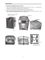
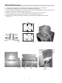
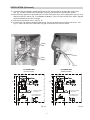
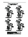
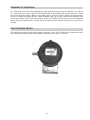
17. Remove the (4) Phillips screws that hold the control panel to the heater and lower the control panel. See
Fig. 17.
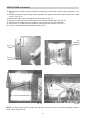
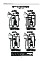
18. Remove and replace the 7/8” plug with the provided 7/8” grommet (located on the left side of the control
panel). See Fig. 18.
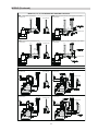
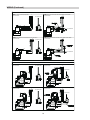
19. Route the 24 VAC harness through the 7/8” grommet, See Fig. 19.
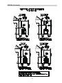
20. Continue to route the harness down through any available grommet hole. See Fig. 20.
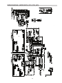
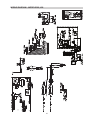
21. Wire the harness along with the installed gas valve harness per the wiring diagram.
22. Reinstall the (4) Phillips screws that hold the control panel to the heater. See Fig. 17.
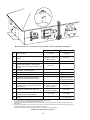
23. Place the front door back onto the heater. Refer to Fig. 1.
7/8”
Supplied
Grommet
Access
Screw
Access
Screw
Fig. 17
Fig. 18
Fig. 19
Fig. 20
NOTE: For Professional heaters, models 268 and 408, it may be necessary to reroute the flexible conduit to
either side of the power vent.
8