1
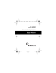
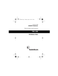
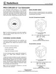
Bi-Directional
Cable-TV Amplifier
The red LED
lights to
indicate power
is on.
15-2505
Introduction
The RadioShack Bi-Directional Cable-TV
Amplifier is ideal for distributing a cable signal to
a remote location. It can also distribute antenna
and HDTV signals. This amplifier increases the
output signal up to 10dB, while minimizing
interference. It also allows bi-directional
communication so you can enjoy pay-per-view
events and interactive TV. It is also compatible
with digital cable modems. The amplifier can be
mounted on a wall or placed on a table or other
indoor surface.
Step Three
Front View
INPUT — Connect
a coaxial cable
here to connect to
your cable system.
OUTPUT —
Connect a coaxial
cable here to
connect to the
receiver (TV or
VCR).
GAIN MIN/MAX —
Adjust until the best
picture quality is
received.
Step One
Step Two
Selecting a Location
Routing Cables
Select a location for your amplifier that is close to
your input source and an AC outlet. You can
mount the amplifier on a wall or other surface
using #6 screws (not supplied).
• Do not place the amplifier outdoors.
• To keep exposed cable to a minimum, you can
also place the amplifier in your attic.
• To prevent interference, do not place the
amplifier within six inches of any other
electronic device.
Route 75-ohm (RG-6 or RG-6QS) coaxial cable from the amplifier to your
input source and receiver. Follow these hints when routing cable:
• Use only as much cable as is necessary to reach from the amplifier to
the input source and receiver.
• Do not route cables where they might be cut, crimped, or crushed by
normal activities.
• For the best appearance, route the cable through the attic and walls, and
terminate each cable in a wall mount box with an F-connector. Wall
mount F-connectors, coaxial cable, and other video accessories are
available at your local RadioShack store.
Making Connections
1. Connect a coaxial cable to your input source.
To connect more than one input source to the
amplifier, use a high isolation A/B switch or
video selector to switch between inputs.
2. Connect the coaxial cable from your cable box
or antenna (input source) to the amplifier’s
INPUT terminal.
3. Connect one end of a coaxial cable to your
output device (TV, cable modem)and the other
end to the amplifier’s OUTPUT terminal.
4. Connect the supplied AC adapter to the jack
on the amplifier.
5. Plug the AC adapter into a standard AC outlet.
The amplifier’s red LED lights when it has
power.
6. Turn on the receiver.
7. Use a flat-head screwdriver to adjust
GAIN MIN/MAX until you get the best picture.
Safety Instructions
• Read and retain all safety and operating instructions.
• This appliance should not be used near water, such as near a
bathtub, washbowl, kitchen sink, or laundry tub.
• The amplifier should be situated so that its location does not
interfere with its proper ventilation.
• This amplifier should be connected to a power supply of the
type described in the operating instructions or marked on the
amplifier.
• Do not attempt to defeat the grounding or polarization
components of this amplifier.
• Wipe the amplifier with a damp cloth occasionally to keep it
looking new. Do not use harsh chemicals, cleaning solvents, or
strong detergents to clean the amplifier.
• The power cord of the amplifier should be unplugged from the
outlet when left unused for extended periods of time.
• Do not allow liquids to spill through the amplifier’s openings.
• The amplifier should be situated away from heat sources such
as radiators, heat registers, stoves, or other appliances.
Temperature extremes can shorten the life of electronic
devices and distort or melt plastic parts.
• If an outside antenna is connected to the receiver, be sure the
antenna system is grounded to provide some protection
against voltage surges, built-up static charges, and lightning
strikes. Section 810 of the National Electric Code (NEC),
ANSI/NFPA NO. 70-1990, provides information with respect to
proper grounding of the mast and supporting structure,
grounding of the lead-in wire to an antenna discharge unit, size
of grounding conductors, location of antenna-discharge unit,
connection to grounding electrodes, and requirements for the
grounding electrode.
• The CATV system installers attention should be directed to
Article 820-40 of the NEC that provides guidelines for proper
grounding and, in particular, specifies that the cable ground
shall be connected to the grounding system of the building, as
close to the point of cable entry as practical.
Notes
• Do not use pliers to tighten screw-on F-connectors.
• Never connect both an outdoor antenna and the output from
the amplifier to the antenna input of your TV or VCR without
using a high isolation A/B switch. Doing so could cause
interference with other nearby receivers.
• For an additional grounding method, remove a rubber foot
from the amplifier and back out the #6 grounding screw. Place
a grounding wire over the grounding screw and tighten the
screw back into the housing.
• In extremely long cable runs (distances over 200 feet),
additional amplification might be needed.
Specifications
FCC Information
WARNING: To reduce the risk of fire or shock hazard, do not expose this product to rain or moisture.
.
.CAUTION..
The lightning symbol is intended to alert
you to the presence of uninsulated
dangerous voltage within this product’s
enclosure that might be of sufficient
magnitude to constitute a risk of electric
shock. Do not open the product’s case.
!
RISK OF ELECTRIC SHOCK
DO NOT OPEN
CAUTION: TO REDUCE THE RISK OF
ELECTRICAL SHOCK, DO NOT REMOVE
COVER OR BACK. NO USERSERVICEABLE PARTS INSIDE. REFER
SERVICING TO QUALIFIED PERSONNEL.
!
The exclamation symbol is
intended to inform you that
important operating and
maintenance instructions are
included in the literature
accompanying this product.
Cautions:
!
You must use a Class 2 power source that supplies 12V DC and delivers at least 100 mA. Its center tip must be set to positive and its plug must fit the amplifier's adapter jack. The supplied adapter
meets these specifications. Using an adapter that does not meet these specifications could
damage the amplifier or the adapter.
Always connect the AC adapter to the amplifier before you connect it to AC power. When you finish, disconnect the
adapter from AC power before you disconnect it from the amplifier.
FCC Declaration of Conformity
This device complies with Part 15 of the FCC Rules. Operation is subject to the following two conditions: (1) this
device may not cause harmful interference, and (2) this device must accept any interference received, including
interference that may cause undesired operation.
Product:
Model:
Responsible Party:
Phone:
Bi-Directional
Cable-TV Amplifier
15-2505
RadioShack
100 Throckmorton
Fort Worth, TX 76102
817-415-3200
The FCC Wants You to Know
This equipment has been tested and found to comply with the limits for a Class B digital device, pursuant to Part 15 of
the FCC Rules. These limits are designed to provide reasonable protection against harmful interference in a
residential installation. This equipment generates, uses and can radiate radio frequency energy and, if not installed and
used in accordance with the instructions, may cause harmful interference to radio communications.
However, there is no guarantee that interference will not occur in a particular installation. If this equipment does cause
harmful interference to radio or television reception, which can be determined by turning the equipment off and on, the
user is encouraged to try to correct the interference by one or more of the following measures:
• Reorient or relocate the receiving antenna.
• Increase the separation between the equipment and receiver.
• Connect the equipment into an outlet on a circuit different from that to which the receiver is connected.
• Consult your local RadioShack store or an experienced radio/TV technician for help.
• If you cannot eliminate the interference, the FCC requires that you stop using your amplifier.
• Changes or modifications not expressly approved by RadioShack may cause interference and void the user’s
authority to operate the equipment.
Forward Path:
Operating Frequency Range...... 54–1000 MHz
Gain .............................................. Up to 10 dB
Gain Adjustment Range............................ 8 dB
Reverse Path:
Operating Frequency Range .......... 5– 40 MHz
Insertion Loss ........................................... 5 dB
Adapter Input Voltage ..................... 105–135V
Power Usage ........................................... <2W
Power Line Frequency ..................... 50–60 Hz
Dimensions (HWD) ...... 11/2 x 33/4 x 51/2 Inches
(3.81 x 9.53 x 13.97 cm)
Weight ................................ 6.72 oz (190.51 g)
Specifications are typical; Individual units might
vary. Specifications are subject to change and
improvement without notice.
Limited 90-Day Warranty
This product is warranted by RadioShack against manufacturing defects in material and workmanship under normal use for 90 (ninety) days from the date of purchase from RadioShack companyowned stores and authorized RadioShack franchisees and dealers. EXCEPT AS PROVIDED
HEREIN, RadioShack MAKES NO EXPRESS WARRANTIES AND ANY IMPLIED WARRANTIES,
INCLUDING THOSE OF MERCHANTABILITY AND FITNESS FOR A PARTICULAR PURPOSE,
ARE LIMITED IN DURATION TO THE DURATION OF THE WRITTEN LIMITED WARRANTIES
CONTAINED HEREIN. EXCEPT AS PROVIDED HEREIN, RadioShack SHALL HAVE NO LIABILITY OR RESPONSIBILITY TO CUSTOMER OR ANY OTHER PERSON OR ENTITY WITH
RESPECT TO ANY LIABILITY, LOSS OR DAMAGE CAUSED DIRECTLY OR INDIRECTLY BY
USE OR PERFORMANCE OF THE PRODUCT OR ARISING OUT OF ANY BREACH OF THIS
WARRANTY, INCLUDING, BUT NOT LIMITED TO, ANY DAMAGES RESULTING FROM INCONVENIENCE, LOSS OF TIME, DATA, PROPERTY, REVENUE, OR PROFIT OR ANY INDIRECT,
SPECIAL, INCIDENTAL, OR CONSEQUENTIAL DAMAGES, EVEN IF RadioShack HAS BEEN
ADVISED OF THE POSSIBILITY OF SUCH DAMAGES.
Some states do not allow limitations on how long an implied warranty lasts or the exclusion or limitation of incidental or consequential damages, so the above limitations or exclusions may not apply to
you.
In the event of a product defect during the warranty period, take the product and the RadioShack
sales receipt as proof of purchase date to any RadioShack store. RadioShack will, at its option,
unless otherwise provided by law: (a) correct the defect by product repair without charge for parts
and labor; (b) replace the product with one of the same or similar design; or (c) refund the purchase
price. All replaced parts and products, and products on which a refund is made, become the property of RadioShack. New or reconditioned parts and products may be used in the performance of
warranty service. Repaired or replaced parts and products are warranted for the remainder of the
original warranty period. You will be charged for repair or replacement of the product made after the
expiration of the warranty period.
This warranty does not cover: (a) damage or failure caused by or attributable to acts of God, abuse,
accident, misuse, improper or abnormal usage, failure to follow instructions, improper installation or
maintenance, alteration, lightning or other incidence of excess voltage or current; (b) any repairs
other than those provided by a RadioShack Authorized Service Facility; (c) consumables such as
fuses or batteries; (d) cosmetic damage; (e) transportation, shipping or insurance costs; or (f) costs
of product removal, installation, set-up service adjustment or reinstallation.
This warranty gives you specific legal rights, and you may also have other rights which vary from
state to state
RadioShack Customer Relations, 200 Taylor Street, 6th Floor, Fort Worth, TX 76102
12/99
©2003 RadioShack Corporation.
All Rights Reserved.
RadioShack and RadioShack.com are trademarks
used by RadioShack Corporation.
15-2505
Printed in China
10A03