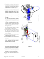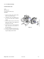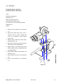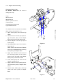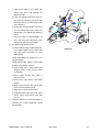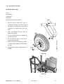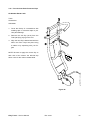
1
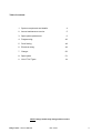
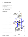
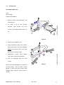
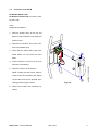
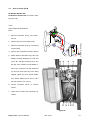
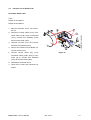
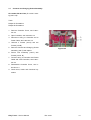
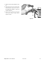
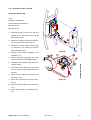
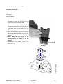
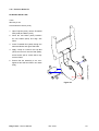
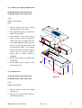
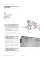
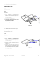
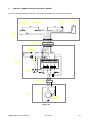
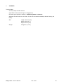
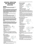
Service Manual Easy Travel – Service Manual Rev. 0401 2 Table of contents: 1. System components and details 4 2. Annual maintenance service 5 3. Spare parts replacement 6 4. Programming 46 5. Fault finding 48 6. Electrical wiring 49 7. Charger 50 8. Spare parts 51 9. List of Tool Types 54 NOTE: Design details may change without notice Easy Travel – Service Manual Rev. 0401 3 1. SYSTEM COMPONENTS AND DETAILS 1.1 EasyTravel parts – (Figure 1) 1. Battery pack (detachable) 2. Front column (detachable) 3. Column lock/release triggers 4. Controller cover 5. Charging socket (Fig. 1A) 6. Front drive wheels 7. Foot platform 8. Seat shell 9. Seat cushions 10. Serial # up to and including: folding seat latch 11. Rear wheel 12. Folded frame lock pin 13. Platform bottom lock pin 14. Utility basket (holding capacity 9kg) 15. Charger and connecting cables (Fig. 1B). 16. Control Panel 17. Freewheel switch 1.2 Control Panel – Figure 2 1. Switch 2. Hand control lever (right and left) 3. Speed adjusting knob 4. Indicator light (LED) 5. From serial # 0307077and onwards or starting with 11B: Battery Level Indicator 6. Hand-grips BELL: If the user requires an audible warning device, a standard bicycle bell can be attached to the handlebar. Easy Travel – Service Manual Rev. 0401 4 2. SERVICE For reasons of safety and the prevention of accidents caused by wear which is not detected in time, the EasyTravel should be tested and serviced once a year. All safety-related components of the EasyTravel should be checked and serviced, safety and functional tests should be performed. It is important to detect initial wear in time and to use exclusively original spares, or such parts that were authorized by the manufacturer. Test the following maintenance items: The components of the EasyTravel frame for overload and initial cracks. Wear of tires on wheels. All screws and attachments for safe securing, cable connections for wear, and the mechanisms of the EasyTravel for correct functioning. The proper functioning of the electronic system and brakes. For serial # up to and including 0304599: the collector brushes of Figure 3 the electric motor (3-A) for wear. Wear limit is approx. 7 mm. Easy Travel – Service Manual Rev. 0401 5 3. SPARE PARTS REPLACEMENT 3.1 Control Panel Assembly Kit number E0-00-1-040 (for serial # up to and including 0307076) Kit Number E0-00-1-202 (for serial # 0307077 and onwards) Kit Number E0-00-1-701 (for serial # with 13 digits, starting with 11B (Taiwan)) Tools: Phillips #2 Screwdriver For serial # and onwards, see next page. 1. Push Handgrips (4-A) outwards 2. Open Screws (4-B) and remove Control Panel Cover (4-C) 3. Disconnect the Control Cable (4-D) 4. Open Screws (4-E) and remove Control Panel (4-F) 5. Open Screws (4-N) and remove Panel Bottom Cover (4-P) 6. Place new Bottom Cover (4-P) and secure it with Screws (4-N) 7. Secure new Control Panel (4-F) with Screws (4-E) 8. Connect the Control Cable (4-D) to Control Panel (4-F) 9. Secure Control Panel Cover (4-C) with Screws (4-B) 10. Push Handgrips (4-A) back over the Cover 11. Check all Control Panel functions: indication, drive, brake and speed control Figure 4 Easy Travel – Service Manual Rev. 0401 6 Kit Number E0-00-1-202 Kit Number E0-00-1-701 Tools: Phillips #2 Screwdriver 1. Open Screws (5-A) and remove top and bottom Control Panel Cover (5-B, C) 2. Disconnect the Control Cable (5-D) 3. Open Screws (5-E) and remove Control Panel (5-F) 4. Secure new Control Panel (5-F) with Screws (5-E) 5. Connect the Control Cable (5-D) to Control Panel (5-F) 6. Secure top and bottom Control Panel Cover (5-B, C) with Screws (5-A) 7. Check all Control Panel functions: indication, drive, brake and speed control Figure 5 Easy Travel – Service Manual Rev. 0401 7 3.2 Handgrip pair Kit number E0-00-1-070 Tools: Silicone spray Phillips #2 Screwdriver 1. Remove Control Panel Assembly, see instructions 3.1 2. For serial # up to and including 0307076: open Screws (6-A) and remove Control Panel Bottom Cover (6B) Figure 6 3. Remove the Handgrips, (7-A) 4. Spray Handlebars (7-B) of the Column Frame and inside of the new Handgrips lightly with Silicone Spray and push them onto the Column Frame 5. Reassemble Control Panel Bottom Cover and Control Panel Assembly 6. Push the Handgrips back over both Covers Figure 7 NOTE: Check that Handgrips do not slide off of Covers easily – this can cause a safety hazard if control lever gets caught under Handgrip edge. Remove excess silicon if needed. Easy Travel – Service Manual Rev. 0401 8 3.3 Controller Cover ET1B Kit Number E0-00-1-034 Kit Number E0-00-1-705 (for serial # starting with 11B) Tools: Phillips #2 Screwdriver 1. Remove Screws (8-A) at the top and bottom of the Controller Cover (8-B) and remove Cover 2. Disconnect Connector (8-C) from Interface Circuit Board (8-D) 3. Check that the solder tabs of the Freewheel Switch on new Cover are bent apart 4. Insert Connector of new Cover (8-C) to Interface Circuit Board 5. Secure the Cover on the Column NOTE: Ensure that the Power Cable is routed under the Controller (see Figure 10) and that it will not be pinched when closing and securing the Cover Figure 8 6. Check drive, brake and freewheel operation Easy Travel – Service Manual Rev. 0401 9 3.4 Solo Controller ET1B Kit Number E0-00-1-032 Kit Number E0-00-1-704 (for serial # starting with 11B) Tools: Short Phillips #2 Screwdriver Pliers 1. Remove Controller Cover, see instruction 3.3 2. Detach wiring from Controller (9-A) 3. Remove Controller (9-A) by unscrewing Screws (9-B) 4. Secure new Controller to Column Frame 5. Attach Wires to Controller (Fig. 9a): from Figure 9 Battery Contacts Assembly, the red wire (A) to “B+” tab (B), the black (C) to “B-“ tab (D); from Interface Circuit Board insert 11-pin connector into top socket P2 (E); the two white wires (F) to the white capped cables (G) from Power Cable; from Power Cable the #1 wire to “M+” tab (H), the #2 to “M-“ tab (J) 6. Secure Controller Cover to Column Frame 7. Check drive, brake and freewheel operation Figure 9a Easy Travel – Service Manual Rev. 0401 10 Kit Number E0-00-1-704 (for serial # starting with 11B) Tools: Short Phillips #2 Screwdriver Pliers 1. Remove Controller Cover, see 3.3 2. Open Screws (10-A), remove Controller Top and plastic protection sheet 3. Detach wiring from Controller 4. Open Screws (10-B) on reverse side of Steering Column and remove Controller 5. Secure new Controller to Column Frame 6. Attach Wires to Controller (Fig. 10a): Figure 10 a. Control Cable (C); b. from Contacts and Charging Socket Assembly: i. the brown wire to connector (B), ii. the white wire to connector (F), iii. the red wire to “B+” tab, the black to “B-“ tab (D); iv. the two red capped wires (coming from connector (F)) to the white and yellow/green cables (G) from Power Cable; c. from Power Cable the #1/red wire to “M+” tab, #2/black wire to “M-“ tab (E) 7. Place plastic protection sheet and secure Controller Top Cover with Screws Figure 10a (10-A) 8. Secure Controller Cover, see 3.3 9. Check drive, brake and freewheel operation Easy Travel – Service Manual Rev. 0401 11 3.5 Battery Contacts Kit number E0-00-1-059 Tools: Phillips #2 Screwdriver 1. Remove Controller Cover, see instruction 3.3 2. Disconnect wiring to Controller (11-A) and Interface Circuit Board (11-B) 3. Unscrew Screws (11-C) and remove Battery Contacts Assembly (11-D) 4. Secure new Battery Contacts Assembly (11-D) with Screws (11-C) 5. Connect Wiring (11-A) to Controller (red to “B+” tab, black to “B-“ tab), Connector (11-B) onto Interface Circuit Board 6. Reassemble Controller Cover, see instruction 3.3 7. Check drive, brake and freewheel operation Figure 11 Easy Travel – Service Manual Rev. 0401 12 3.6 Interface Circuit Board ET1B Kit number E0-00-1-058 Tools: Phillips #1 Screwdriver Phillips #2 Screwdriver 1. Remove Controller Cover, see instruction 3.3 2. Disconnect Control Cable (12-A), Freewheel Cable (12-B), wiring to Controller (12-C), Contact Pins Assembly (12-D) and to Power Cable (12-E) 3. Unscrew 3 Screws (12-F) and remove Interface Circuit Board (12-G) 4. Secure new Interface Circuit Board (12G) with Screws (12-F) Figure 12 5. Connect Control Cable (Fig. 12-A), Freewheel Cable (12-B), wiring to Controller (12-C), Contact Pins Assembly (12-D) and Power Cable (12-E) 6. Reassemble Controller Cover 7. Check drive, brake and freewheel operation Easy Travel – Service Manual Rev. 0401 13 3.7 Contacts and Charging Socket Assembly Kit number E0-00-1-703 (for serial # starting with 11B) Tools: Phillips #1 Screwdriver Phillips #2 Screwdriver 1. Remove Controller Cover, see instruction 3.3 2. Open Controller, see instruction 3.4 3. Disconnect wiring to Controller and to Power Cable, see instruction 3.4 4. Unscrew 3 Screws (12a-A) and two Screws (12a-B) 5. Remove Contacts and Charging Socket Figure 12a Assembly (12a-C) and replace 6. Secure new Assembly (12a-C) with Screws (12a-A, B) 7. Connect wiring to Controller and Power Cable and close Controller, see instruction 3.4 8. Reassemble Controller Cover, see instruction 3.3 9. Check drive, brake and freewheel operation Easy Travel – Service Manual Rev. 0401 14 3.8 Control Cable Kit number E0-00-1-054 Kit Number E0-00-1-702 (for serial # starting with 11B) Tools: Phillips #2 Screwdriver 1. Open Control Panel Cover, see instruction 3.1 2. Open Controller Cover, see instruction 3.3 3. Disconnect Control Cable from Control Panel (5-C) and Interface Circuit Board (12-A)/Controller (10a-C) 4. Remove Control Cable 5. Insert new Control Cable (if needed, remove the Paint Protector and replace it with a new one after the Control Cable is inserted, see instruction 3.32) 6. Connect Control Cable to Control Panel and Interface Circuit Board/Controller 7. Reassemble Controller Cover and Control Panel Cover, see instructions 3.1 and 3.4 8. Check all Control Panel and Controller functions: drive, brake, speed and indication Easy Travel – Service Manual Rev. 0401 15 3.9 Motor End Cover ET1B Kit Number E0-00-1-083 (for motor types E0-00-1-036 and E0-00-1-092) Tools: Phillips #2 Screwdriver 1. Unscrew Screw (13-A) and remove Cover (13-B) 2. Note the motor wire routing and maintain it in position NOTE: If force is needed to fit Cover, check the wire routing and ensure that it will not be pinched 3. Secure new Cover (13-B) with Screw Figure 13 (13-A) Kit Number E0-00-1-096 (for motor type E0-00-1-094) Tools: Phillips #2 Screwdriver 1. Unscrew Screws (14-A) and remove Cover (14-B) 2. Note the motor wire routing and maintain it in position NOTE: If force is needed to fit Cover, check the wire routing and ensure that it will not be pinched 3. Secure new Cover (14-B) with Screws (14-A) Figure 14 Easy Travel – Service Manual Rev. 0401 16 3.10 Motor Brushes Kit Number E0-00-1-037 (for serial # up to and including 0304599) Tools: Phillips #2 Screwdriver Flat Blade Screwdriver (For EasyTravel with serial number up to and including 0212052: Hot Air Gun (if available) Soldering Iron and Solder) Please refer to Figure 13 1. Remove the Motor End Cover, see instruction 3.8 2. Remove the plastic Brush Cap (C) and pull the Brush gently from its housing 3. Remove Power Cable wire For serial # up to and including 0212052: Remove heat-shrink insulation and unsolder the Brush (Fig. 15) being replaced 4. Insert the new Brush carefully into its Figure 15 housing and secure with Brush Cap (C) NOTE: Ensure that the Brush is fully inserted freely and smoothly and that the spring is not caught in the housing 5. Connect Power Cable wire to contact tab For serial # up to and including 0212052: a. Place new heat-shrink insulation sleeves over wires and re-solder wiring to contact tab NOTE: Ensure good tinning and secure connection b. Secure insulation sleeves in place with hot air gun or soldering iron 6. Note the motor wire routing and maintain it in position. 7. Secure Motor Cover, see instruction 3.8 8. Check drive and brake operation Easy Travel – Service Manual Rev. 0401 17 3.11 Power Cable to Motor ET1B Kit Number E0-00-1-056 (for serial # up and including 0212052) Kit Number E0-00-1-093 (for serial 0212053 up to 0304599) Kit Number E0-00-1-095 (for serial 0304600 and onwards) Kit Number E0-00-1-706 (for serial starting with 11B) to # # # Tools: Phillips #2 Screwdriver Pliers Cutter Cable Tie Tensioning Tool (For serial # up to and including 0212052: Soldering Iron Solder Hot Air Gun) The wheels MAY be removed to facilitate easier access for the replacement of parts, see instruction 3.11 Fig. 16a refers to serial # up to and including Figure 16a 0212052, fig. 16b refers to serial # 0212053 up to 0304599, fig. 16c refers to serial # 0304600 and onwards. 1. Remove the Motor Cover, see instruction 3.8 (for serial # starting with 11B: remove heat shrink) 2. Remove Cable Ties (16-A) from Motor and Securing Clip (16-B) on the underside of the Adapter Block 3. Remove Wires from Terminals (16-C) and Brakes (16-D) For serial # up to and including 0212052: Remove heat-shrink insulation and unsolder the Wires from the Terminals (16C) and Brakes (16-D) on the Motor 4. Remove Controller Cover, see instruction 3.3 5. Detach the Wires from the Controller (17-A) and Interface Circuit Board (17-B) 6. Carefully pull the Power Cable out of the Figure 16b Column Frame Easy Travel – Service Manual Rev. 0401 18 7. Thread the new Power Cable from the Controller-end into the hole in the Column Frame out of tube and under the Adapter Block, as depicted in Fig. 16 8. Connect the #1/red insulated Wire end to positive/red colored Terminal, the #2/black insulated Wire end to negative/black Terminal, the #3 and green Wire to white Wires from electromagnetic Brake (For serial # up to and including 0212052: a. Place new heat-shrink insulation sleeves over wires and solder the #1 long Wire end to positive/red colored Terminal, the #2 short Wire end to nega- Figure 16c tive/black colored Terminal, the #3 and green wire to white Wires from the electromagnetic Brake b. Secure insulation sleeves in place with hot air gun or soldering iron) 9. Secure the Cable to the Motor with Cable Ties (16-A) and trim ends (for serial # starting with 11B: Place new heat shrink over Motor 10. Secure the cable to the underside of the Adapter Block with Clip (16-B) 11. Secure the Motor Cover over the end of the Motor NOTE: If force is needed to fit Motor Cover, check the wire routing and ensure that it will not be pinched 12. Attach from the Power Cable the black insulated #1 Wire End to “M+” tab, the red insulated #2 to “M-“ tab on Controller Figure 17 and the two white insulated Wire Ends to the Wires from Interface Circuit Board 13. Secure Controller Cover to the Frame, ensure that no wires will be pinched or damaged by the Cover or the Screws 14. Check drive, brake and freewheel function Easy Travel – Service Manual Rev. 0401 19 3.12 Front Wheel Assembly Kit Number E0-00-1-069 Tools: Allen Key 6 mm Loctite Adhesive #242 (1312) Soft Mallet 1. Remove old Cap (18-A), Screw (18-B), Disk (18-C) and Wheel (18-D) 2. Thoroughly clean the threaded hole in the end of the Axle (18-E) of adhesive residue 3. Slide the Wheel (18-D) onto Axle (18-E) aligning the groove in the Adapter with the Roll Pin on the Axle 4. Place Disk (18-C) on Screw (18-B) and apply Loctite #242 (1312) adhesive to the screw thread Figure 18 5. Secure the assembly with Screw (18-C). 6. Fit new Cap (18-A) on the Wheel (18-D) by gently tapping it with a mallet Easy Travel – Service Manual Rev. 0401 20 3.13 Gear Motor Kit Number E0-00-1-035 (ET1) Kit Number E0-00-1-094 (ET1B) Tools: Phillips #2 Screwdriver Allen Key 5 mm Cable Tie Tensioning Tool Loctite Adhesive #242 (1312) (For serial # up to and including 0212052: Soldering Iron Solder) 1. Remove Front Wheels, see instruction 3.11 2. Remove the Motor End Cover, see instruction 3.8 (for serial # starting with 11B it is not needed to remove Motor End Cover) 3. Detach Power Cable from Gear Motor, see instruction 3.10 4. Remove the Screws (19-A) securing the Gear Motor to the Adapter Block 5. Apply Loctite to the Screws (19-A) and secure with them the new Gear Motor to the Adapter Block 6. Attach Power Cable to Gear Motor, see instruction 3.10 7. Secure Motor End Cover, see instruction 3.8 8. Secure Front Wheels, see instruction 3.11 Figure 19 Easy Travel – Service Manual Rev. 0401 21 3.14 Adapter Block Assembly Kit Number E0-00-1-038 Kit Number E0-00-1-707 (for serial # starting with 11B) Tools: Allen key 5 mm Allen Key 8 mm Wrench, open end 19 mm Torque Wrench Loctite Adhesive #242 (1312) Light Grease/Lubricant The wheels MAY be removed to facilitate easier access, see instruction 3.11 1. Open Screw (20-A) and remove Clip (20-B) 2. Unscrew the four Screws (20-D) securing Gear Motor (20-E) to the Adapter Block (20-F) and put Gear Motor aside 3. Remove “Nylock” Lock Nut (21-A) and Screw (21-B) Figure 20 4. Slide Adapter Block (21-C) from Column Frame (21-D) NOTE: Ensure that the Column Release Pin (21-E) is withdrawn before removing and replacing the Adapter Block 5. Apply some Lubricant on the inside of the connecting plates of the Column Frame (21-D) and slide new Adapter Block (21-C) in the Column Frame 6. Insert Screw (21-B) and secure it with “Nylock” Lock Nut (21-A) 7. Apply Loctite to Screws (20-D) and secure Gear Motor (20-E) to Adapter Block (20-F) 8. Secure Power Cable (20-C) with Clip (20-B) and Screw (20-A) to Adapter Block Figure 21 Easy Travel – Service Manual Rev. 0401 22 9. Remove Screw (22-A) holding Pin (22B) 10. Remove the Pin from the new Quick Release Mechanism, apply some Loctite in the thread and position it under the Conical Cap (22-C) 11. Secure the Pin (22-B) to the Cap with Screw (22-A) using a torque wrench, torque to 40 N-m. Figure 22 Easy Travel – Service Manual Rev. 0401 23 3.15 Upgrade from ET1 to ET1B Kit Number E0-00-1-097 Tools: Phillips #1 Screwdriver Short Phillips #2 Screwdriver Allen Key 5 mm Allen Key 6 mm 1. Remove Screws (23-A) at the top and bottom of the Controller Cover (23-B) and remove Cover 2. Disconnect cables connected to Controller (23-C) and Power Cable (23-D) 3. Disconnect Control Cable (24-A), wiring to Controller (Fig. 24-B) and Contact Pins Assembly (24-C) Figure 23 4. Remove Front Wheel Assembly, see instruction 3.11 5. Remove Securing Clip (page 21, 20-B) on the underside of the Adapter Block 6. Carefully pull the Power Cable out of the Column Frame 7. Insert new Power Cable from the motor end into Frame, using the attached ironwire tool 8. Attach Power Cable to Controller, see instruction 3.10 Figure 24 9. Place new Controller Cover, see instruction 3.3 10. Secure new Gear Motor, see instruction 3.12 11. Check drive, brake and freewheel function Easy Travel – Service Manual Rev. 0401 24 3.16 Top Bearing for Steering Axis Kit number E0-00-1-067 Tools: Drive Punch Press/Vise/Mallet 1. Remove Adapter Block, see instruction 3.13 and place it so that the bearing is free to come out of the Pin Housing (26-B) 2. Remove the Bearing by tapping it with a Drive Punch alternatively through each one of the holes in the Top Pin Housing (Fig. 25A) 3. Place the new Bearing (26-A) in the Top Pin Housing (26-B) and press/tap it into the Pin Housing ! NOTE: Make sure the bottom of the Bearing reaches its seating in the Pin Housing 4. Reassemble the Adapter Block, see instruction 3.13 Figure 25 Figure 26 Easy Travel – Service Manual Rev. 0401 25 3.17 Column Release Cable Kit Kit Number E0-00-1-080 Tools: Phillips #2 Screwdriver Wrench, open end 8 mm Allen key 3 mm Wire Cutter Pliers Crimp Tool Loctite Adhesive # 496 (3854) Light grease/lubricant 1. Remove Control Panel Cover, see instruction 3.1 2. Remove Cable End Cone, Vinyl Caps and Screws (2x) and open Cable Locks 3. Slide Release Bushing out of Column Frame and remove Cable with Lock Pin and Spring 4. Thread Column Lock Pin (27-A) and Spring (27-B) onto the Column Lock Pin Cable (27-C) 5. Thread the Cable through the large hole in Connecting Plate (27-D), Column Lock Pin Housing (27-E) and the small hole in Connecting Plate (27-F) 6. Apply some lubricant to Lock Pin (27-A) 7. Thread the Cable Guide (27-G) onto the Cable and thread the cable into the Cable Guide Adjustable Stop (27-H) and through the Tube of Column Frame (27J) 8. Thread the Release Bushing (27-K) with Figure 27 the threaded hole down onto the Cable making sure that the Cable passes through the two Cable Locks (27-L). Bring the Release Bushing (27-K) to its approximate position and lightly secure it with the Cable Locks (27-L) Easy Travel – Service Manual Rev. 0401 26 9. Apply Loctite to Screw (27-N) and secure Column Latch Bushing (27-M) with it onto Release Bushing (27-K) 10. Take up the slack in the Cable (27-C) so that the end of the Column Lock Pin (27A) is flush with the outside of Connecting Plate (27-D) 11. Release the two Cable Locks (27-L) and bring the Release Bushing (27-K) to its final position, Latch Bushing (27-M) reaching the bottom of slot in Column Frame Tube (27-J). Tighten the two Cable Locks (27-L) 12. Place the two Set Screws (27-P) in the upper threaded holes of the Release Bushing (27-K) and slide the two Vinyl Caps (27-Q) onto them. NOTE: do not over-tighten the Screws (27-P) against the Cable. 13. Trim Cable to approximately 25 mm. (1") beyond the end of the Column Frame Tube. Crimp the Cable End Cone (27-R) onto the end of the Cable. 14. Test the function of the Column Lock Pin Assembly and adjust as necessary. 15. Fold Frame with Column attached to it, ensure the short pin (27-N) slides over the frame latch without forcing it and holds the frame in a latched position. 16. Release the latch, ensure the short pin (27-N) releases over the frame latch crown without jamming (low effort) Easy Travel – Service Manual Rev. 0401 27 3.18 Black Vinyl Cap Kit Number E0-00-1-078 Tools: Screwdriver and/or Pliers Refer to Figure 27 1. Pry Cap (27-Q) off with Screwdriver or pair of Pliers; be careful not to chip the paint 2. Place new Cap, make sure it covers the whole Set Screw (27-P) Easy Travel – Service Manual Rev. 0401 28 3.19 Protector Roller Kit Kit Number E0-00-1-081 Tools: Allen Key 5 mm Loctite Adhesive # 242 (1312) 1. Open Cap Nut (28-A), remove Threaded Rod (28-B) and Roller (28-C) 2. Place the new Roller (28-C) between the two Plates (28-D) and align with holes 3. Insert Threaded Rod (28-B) though the holes and Roller and right hand Plate 4. Apply a drop of Loctite to the Cap Nut (28-A) and screw it onto the Rod (28-B); avoid excess spill of Loctite which may lock the Roller 5. Ensure that the assembly is not overtightened and that the Roller can rotate freely Figure 28 Easy Travel – Service Manual Rev. 0401 29 3.20 Column Frame Kit Number E0-00-1-001 (Red ET1) Kit Number E0-00-1-003 (Red ET1B) Kit Number E0-00-1-002 (Blue ET1) Kit Number E0-00-1-004 (Blue ET1B) Kit Number E0-00-1-005 (Silver ET1B) Tools: Phillips #1 Screwdriver Phillips #2 Screwdriver Soldering Iron Allen Key 2 mm Allen Key 5 mm Allen Key 6 mm Pliers Cutter Cable Tie Tensioning Tool The new Column Frame is issued with a Control Cable, Power Cable and Column Release Cable. 1. Remove from the old Column Frame: a. Control Panel Assembly, see instruction 3.1 b. Controller Cover and Controller, see instructions 3.3 and 3.4 c. Battery Contacts, see instruction 3.5 d. Interface Circuit Board, see instruction 3.6 e. Adapter Block, see instruction 3.13; there is no need to disassemble Gear Motor from Adapter Block, just unsolder Power Cable from Motor End, see instruction 3.10 2. Assemble the removed articles to the Figure 29 new Column Frame Easy Travel – Service Manual Rev. 0401 30 3.21 Battery Case / Battery Replacement Kit Number E0-00-1-020 (Normal size) Kit Number E0-00-1-021 (Jumbo size) Tools: Phillips #2 Screwdriver Pliers 1. Remove Screws (30-A) from Battery Case and remove Cover (30-B) 2. Remove Batteries (30-C) from Case and detach Wires (30-D/E) 3. Place Batteries in new Case (-H) and attach red Wire (30-D) to positive/red marked Tab (30-F) and black Wire (30E) to negative/black marked Tab (30-G) NOTE: It is recommended to attach first the appropriate Wires to the Battery closest to the base of the Case and then insert it fully into the case; repeat in same order for Battery closest to Handlebar 4. Ensure that no Wires are caught under the Batteries 5. Secure Battery Cover (30-B) to Case with Screws (30-A) 3.22 Battery Cover Kit Number E0-00-1-022 (Normal size) Figure 30 Kit Number E0-00-1-025 (Jumbo size) Tools: Phillips #2 Screwdriver 1. Remove Screws (30-A) and Battery Cover (30-B) 2. Secure new Cover (30-B) to Case (30H) with Screws (30-A) Easy Travel – Service Manual Rev. 0401 31 3.23 Platform Lock Pin Kit Kit Number E0-00-1-079 (serial # up to and including 0304999) Kit Number E0-00-1-206 (serial # 0305001 and onwards) Tools: Pliers Wrench, open end 8 mm Phillips #2 Screwdriver Allen Key 2 mm Allen Key 4 mm (2x) Cutter Crimp tool Loctite Adhesive #242 (1312) Small Rod (diameter 15 mm) Figure 32 refers to Seat model E0-00-1-060, Figure 33 refers to Seat model E0-00-1-201. 1. Close the Seat in the folded down position (for the model with a lock, which is situated on the upper left hand side of the Seat: lock it) 2. Cut the Cone End (32-M, 33-D) from the Cable (31-C) and remove Cable Figure 31 3. Thread the Bottom Lock Pin (31-A) and Spring (31-B) onto the Bottom Lock Pin Cable (31-C) 4. Thread the Cable through the Bottom Lock Pin Housing (31-D) 5. Thread the Cable Backstop (31-E) onto the Cable and screw it into the Housing so that approximately 3 mm. of thread is still visible and tighten it 6. Thread the Bottom Lock Cable Guide (31-F) onto the Cable and thread the Cable Guide through the Cable Sleeves (31-G) 7. For Seat model E0-00-1-060: a. Thread the Cable Guide through the Figure 32 Cable Guide Bracket (32-H) b. Thread the first Cable Lock (32-J) onto the Cable and thread the Cable through the Cable Bush (32-K) Easy Travel – Service Manual Rev. 0401 32 c. Take up the slack in the Cable and tighten the first Lock against the Bracket (32-H) d. Push the Spring (31-B) and Lock Pin (31-A) into the Housing (31-D) so that the end of the Pin is flush with the end of the Housing e. Thread the second Cable Lock (32-L) onto the Cable, take up the slack and tighten the Lock against the Bushing (32-L) f. Trim the Cable to approximately 20 mm. and crimp the Cable End Cone (32-M) onto the end of the Cable 8. For Seat model E0-00-1-201: a. Insert Cable through Cable Stops (33- Figure 33 A) in Cable Holder (33-B), ensure that the Cable does not slack and close Cable Stops NOTE: Seat Backrest needs to be in an upright position NOTE: Keep Cable Holder in place with a small rod (diameter 15 mm) b. Secure End (33-C) with Cable End Stopper (33-D); ensure that the bend is outwards c. Place Cable Holder with Stud in Groove (33-E) d. Place Pivot Cap (33-F) over Cable Holder e. Apply some Loctite in Nut (33-G) and screw on Pivot Screw (33-H) f. Apply some Loctite in Nut (33-J) g. Assemble Pivot Cap (33-F) with Pivot Screw (33-H) and secure with Nut (33-J) 9. Test the efficiency of the assembly by unfolding the Frame Assembly, adjust as necessary Easy Travel – Service Manual Rev. 0401 33 3.24 Seat Assembly Kit Number E0-00-1-060 (serial # up to and including 0304999) Kit Number E0-00-1-201 (serial # 0305001 and onwards) Tools: Phillips #2 Screwdriver Pliers Cutter Crimp Tool Loctite Adhesive # 242 (1312) 1. Disconnect the Lock Pin Cable from the seat, see instruction 3.22 2. Remove the two Screws (34-A) holding the Seat (34-D) to the "U" shaped Seat Attachment Bracket (34-B), the Sleeves (34-C) and Seat (34-D) 3. Insert the two frame seat support Figure 34a "horns" (34-E) through the seat holes (34-F) 4. Attach the replacement Seat (34-D) to the Bracket (34-B). Place the Sleeves (34-C) between the holes in the Bracket (34-B) and tighten the two Screws (34A) until any lash is removed. Over tightening may cause friction on the frame tube resulting in higher folding effort. 5. Attach the Lock Pin Cable and adjust its locking function, see instruction 3.22 Figure 34b Easy Travel – Service Manual Rev. 0401 34 3.25 Seat Back Pad Kit Number E0-00-1-061 (up to and including serial # 0304999) Kit Number E0-00-1-204 (serial # 0305001 and onwards) Tools: Phillips #2 Screwdriver 1. Remove the Screw Covers (35-A) 2. Remove the Screws (35-B) and Back Pad (35-C) 3. Align the tubes (35-D) of the Back Pad with the holes in the Seat Back (35-E) 4. Secure Back Pad with Screws (35-B) 5. Place Screw Covers (35-A) Figure 35 Easy Travel – Service Manual Rev. 0401 35 3.26 Seat Bottom Pad Kit Number E0-00-1-062 (up to and including serial # 0304999) Kit Number E0-00-1-203 (serial # 0305001 and onwards) Tools: Phillips #2 Screwdriver Loctite Adhesive # 242 (1312) For removal and attachment of Seat, refer to Figure 38, but without removing the Lock Pin Cable. 1. Remove the two Screws (34-A) holding the Seat (34-D) to the "U" shaped Seat Attachment Bracket (34-B) and the Sleeves (34-C) 2. Remove the Screws (36-A) and Bottom Pad (36-B) 3. Align the tubes (36-C) of the Bottom Pad with the holes in the Seat Bottom (36-D) 4. Secure Bottom Pad (36-B) with Screws (36-B) 5. Attach the Bracket (34-B) to Seat (34C). Place the Sleeves (34-C) between the holes in the Bracket (34-B) 6. Apply Loctite to the two Screws (34-A) and tighten them until any lash is removed. Over tightening may cause friction on the frame tube resulting in higher folding effort. Figure 36 Easy Travel – Service Manual Rev. 0401 36 3.27 Seat Backrest Lock kit Kit Number E0-00-1-063 (up to and including serial # 0304999) Tools: Phillips #2 Screwdriver 1. Remove Screw (37-D), Washer (37-C), Knob (37-B) and Stopping Snib (37-A) 2. Insert new Stopping Snib (37-A) in Seat Bottom 3. Attach Knob (37-B) to Stopping Snib and secure it with Washer (37-C) and Screw (37-D) 4. Check that a some effort is needed to open and close Lock 5. Check opening and closing functions of Lock and Seat Figure 37 Easy Travel – Service Manual Rev. 0401 37 3.28 Seat Attachment Bracket Kit Number E0-00-1-064 (up to and including serial # 0304999) Kit Number E0-00-1-204 (serial # 0305001 and onwards) Tools: Phillips #2 Screwdriver Loctite Adhesive # 242 (1312) Refer to Figure 37 1. Remove the two Screws (34-A) holding the Seat (34-D) to the "U" shaped Seat Attachment Bracket (34-B) and the Sleeves (34-C) 2. Remove the Bracket (34-B) 3. Attach the new Bracket (34-B) to Seat (34-C). Place the Sleeves (34-C) between the holes in the Bracket (34-B) 4. Apply Loctite to the two Screws (34-A) and tighten them until any lash is removed. Over tightening may cause friction on the frame tube resulting in higher folding effort. Easy Travel – Service Manual Rev. 0401 38 3.29 Footrest Platform Kit Number E0-00-1-077 Tools: Cleaning detergent Clamps 1. Remove old Platform (38-A) and any remainders of Adhesive Tape 2. Clean Frame surface (38-B) with a detergent and wipe dry with a clean cloth 3. Remove protective film from Tape sections (38-C) 4. Secure Platform (38-A) to Frame (38-B) with two clamps 5. Leave for 15 minutes before removing the clamps Figure 38 Easy Travel – Service Manual Rev. 0401 39 3.30 Folding Lock Pin Kit Kit Number E0-00-1-065 Tools: Circlip pliers 1. Remove the old Pull Ring (39-F), Circlip (39-E) and Washer (39-D). Extract the old Spring (39-A) and old Pin (39-C) from the Pin Housing (39-B) 2. Insert new Spring (39-A) and Pin (39-C) into Pin Housing (39-B) 3. Apply pressure to the end of the Pin so that it projects through the Pin Housing, place Washer (39-D) and fit Circlip (39E) into its groove at the end of the Pin 4. Insert the Pull Ring (39-F) into the hole in the end of the Pin Figure 39 5. Test the assembly to ensure that the Pin returns to its original position after pulling on the Pull Ring 3.31 Ring for folding lock Kit Number E0-00-1-066 Refer to Figure 39. 1. Remove old Pull Ring from the Pin 2. Insert the Pull Ring (39-F) into the hole in the end of the Pin Easy Travel – Service Manual Rev. 0401 40 3.32 Rear Wheel Assembly Kit Number E0-00-1-068 Tools: Circlip Pliers Screwdriver Soft Mallet Extractor with scratch protection 1. Remove old End Cap (40-C) using a screwdriver. Remove old Circlip (40-B) and Wheel. If needed use an extractor to remove the bearing from the Axle (41) 2. Place new Wheel (40-A) on Axle of Rear Frame (40-D) 3. Fit new Circlip (40-B) into its groove at the end of the Axle 4. Fit new End Cap (40-C) to the end of the Axle using a mallet NOTE: Protect the End Cap with rubber or a cloth; direct sharp blows will deform the Cap 5. Ensure that the Wheel rotates freely on the Axle Figure 40 Figure 41 Easy Travel – Service Manual Rev. 0401 41 3.33 Front Column Paint Protector Clips Kit Number E0-00-1-072 Tools: Screwdriver Soft Mallet 1. Cover the flat tip of a screwdriver with masking tape or electrical tape to prevent paint damage 2. Remove the old Clip (42-A) from the Tube (42-B) by prying on the end 3. Align the new Clip’s slotted stud with the hole in the Tube. Tap it into place using a mallet or by squeezing with your fingers NOTE: Be sure to apply the correct clip on each side of the column: the left-side clip has a notch for the column release slide. Figure 42 Easy Travel – Service Manual Rev. 0401 42 3.34 Flat Cap (front platform) Kit Number E0-00-1-074 Tools: Screwdriver and/or Pliers Soft Mallet 1. Cover the flat tip of a screwdriver with masking tape or electrical tape to prevent paint damage 2. Remove the old Cap (43-A) 3. Tap the Cap (43-A) gently into the Tube end (43-B) using a mallet NOTE: Sharp blows will deform the Cap Figure 43 Easy Travel – Service Manual Rev. 0401 43 3.35 Front Platform Paint Protector Clips Kit number E0-00-1-073 Tools: Screwdriver Soft Mallet 1. Cover the flat tip of a screwdriver with masking tape or electrical tape to prevent paint damage 2. Remove the old Clip (44-A) from the Tube (44-B) by prying on the end 3. Align the new Clip’s slotted stud (44-A) with the hole in the Tube (44-B). Tap it into place using a mallet or by squeezing with your fingers Figure 44 Easy Travel – Service Manual Rev. 0401 44 3.36 Domed Caps (Seat Supports) Kit Number E0-00-1-075 Tools: Screwdriver and/or Pliers Soft Mallet 1. Cover the flat tip of a screwdriver with masking tape or electrical tape to prevent paint damage 2. Remove the old Cap (45-A) 3. Tap the Cap (45-A) gently into the Tube end (45-B) using a mallet NOTE: Sharp blows will deform the Cap Figure 45 3.37 Rear Frame Paint Protector Clips Kit number E0-00-1-071 Tools: Screwdriver Soft Mallet 1. Cover the flat tip of a screwdriver with masking tape or electrical tape to prevent paint damage 2. Remove the old clip (46-A) from the Tube (46-B) 3. Align the new Clip’s slotted stud (46-A) with the hole in the Tube (46-B). Tap it into place using a mallet or by squeez- Figure 46 ing with your fingers. Easy Travel – Service Manual Rev. 0401 45 4. PROGRAMMING OF THE SOLO CONTROLLER 4.1 Introduction The EasyTravel electric system is operated by the Solo Controller manufactured by Penny & Giles Technologies Ltd. (UK). 4.2 The SP1 Programmer The SP1 is a handheld programmer for use with the Solo controller. The programmer is a menu-driven device, which plugs directly into the controller. The SP1b Programmer (Engineering ? Version) can set all of the key controller speed, acceleration and braking characteristics, and allows different settings to be tried out while the programmer is still plugged into the controller. A context-sensitive help Yes function is available to guide users through No the menus and the SP1b can also display error messages from the controller. This allows any electrical Enter problems with the vehicle system to be identified and corrected quickly. Figure 47 WARNING Programming should only be conducted by competent personnel with in-depth knowledge of Penny & Giles electronic controllers. Incorrect programming could result in an unsafe set-up of a vehicle for a user. Tzora Active Systems accepts no liability for losses of any kind if the programming of the controller is altered from factory pre-set values. Easy Travel – Service Manual Rev. 0401 46 The following table shows the Solo Controller settings for the EasyTravel as defined by Tzora Active Systems. 4.3 Function Fast Slow Forward Acceleration 2.0 s 2.0 s Forward Deceleration 0.9 s 1.3 s Reverse Acceleration 3.0s 3.0 s Reverse Deceleration 2.5s 2.5 s Forward Speed 100% 50% Reverse Speed 50% 30% Invert Throttle Polarity No *Power Down Timer* 10 min Current Limit 20A Motor Compensation 200mΩ Hold Factor 152% Mid Current 50%, 10 s Brake Time 0.1s ISO Tests Off Inhibit Polarity Lo Bridge Hold Time 200 ms Throttle Gain 750% Pulse Reverse Alarm No Wig-wag Throttle Yes Low Battery Flash Inhibit No Throttle Deadband 15% Output Voltage 24V TruCharge Cable Resistance 40mΩ TruCharge Cal. 95 Using The SP1b Please contact Tzora Active Systems for more information about and the acquiring of the SP1b Programmer. The Programmer is shipped with an extensive guide. Please read the guide carefully before using the SP1b Programmer. Setting parameters to incorrect values could damage controllers and motors, and invalidate any warranties. Easy Travel – Service Manual Rev. 0401 47 5. FAULT FINDING 5.1 Introduction Tzora Active Systems provides for profound training in Fault Finding to the major distributors of the EasyTravel. Please contact the authorized Tzora Distributor in your country or Tzora for more information. 5.2 Electrical System 5.2.1. Detecting that a Fault has occurred A fault is signaled by a rapid flashing of the status indicator. Care should be taken because the controller gives a low battery warning by a slow flash of the status indicator. This is not a fault, just a reminder that you should charge your batteries. To detect a fault in the Solo Controller, the SP1b Programmer is used. It can detect various faults, for instance a motor wiring fault, a throttle fault, a possible controller fault or a fault in the solenoid brakes. 5.2.2. Fault Diagnosis using the SP1b The SP1b indications should only be used to decide the starting point of your own diagnosis, as it is possible for the controller to indicate a fault in another component even though the controller itself is at fault. Nevertheless, experience has shown that connectors and wiring are the major cause of vehicle electrical problems, so it is necessary to examine these most vulnerable areas first. Further information is to be found in the Programming and Fault Finding Guide that is shipped with the SP1b Programmer. 5.2.3. Servicing of Defective Solo Controllers There are no serviceable parts within the Solo Controller. Consequently, any defective units must be returned to Tzora Active Systems for repair. Opening or making any unauthorized adjustments or modifications to the controller or its components will invalidate any warranty and may result in hazards to the vehicle user, and is strictly forbidden. WARNING Faultfinding and repairs should only be conducted by competent personnel, authorized by Tzora Active Systems. Incorrect repair or tampering could result in a hazardous defect in the EasyTravel. Tzora Active Systems accept no liability for losses of any kind arising from unauthorized adjustment or modification to the EasyTravel. Easy Travel – Service Manual Rev. 0401 48 6. CONTROL CONNECTIONS AND ELECTRICAL WIRING For more information please contact your authorized Tzora Distributor or Tzora Active Systems. Figure 48 Easy Travel – Service Manual Rev. 0401 49 7. CHARGER Technical data: - 24 Volts, 2Amp Constant Current (equivalent to 3A tapered charger in charging time) - Universal Input 100VAC to 240VAC - Suitable anywhere in the world - Automatic Cut-off and then true Float. Can be left connected indefinitely without harming the battery - Size Length: 165 mm (6.5") Width: 80 mm (3.1") Height: 50 mm (2.0") - Weight Easy Travel – Service Manual 550 grams (1.2 lbs.) Rev. 0401 50 8. SPARE PARTS 8.1 List of Spare Parts Kits Part Number Description Included in Kit Control Panel Assembly – MobiGo Control Panel, Top and Bottom Cover, Screws Page E0-00-1-046 E0-00-1-202 6 E0-00-1-701 E0-00-1-070 E0-00-1-034 E0-00-1-705 E0-00-1-032 E0-00-1-704 Handgrip pair 8 Controller Cover ET1B Controller Cover, Screws 9 Controller 10 E0-00-1-059 Battery Contacts Battery contacts, Screws 12 E0-00-1-058 Interface Circuit Board ET1B Screws 13 E0-00-1-703 Contacts and Charging Socket Assembly Screws 14 E0-00-1-054 E0-00-1-702 Control Cable 15 E0-00-1-083 Motor End Cover ET1B Screw E0-00-1-096 Motor End Cover ET1B PV Screws E0-00-1-037 Motor Brushes 16 17 E0-00-1-056 E0-00-1-093 Power Cable ET1B Securing Clip, Screw 18 E0-00-1-069 Front Wheel Assembly Front Wheel, Allen Screw, Washer, Flat Cap 20 E0-00-1-035 Gear Motor ET1 21 Gear Motor ET1B 21 E0-00-1-095 E0-00-1-706 E0-00-1-094 E0-00-1-708 E0-00-1-038 E0-00-1-707 Adapter Block Assembly E0-00-1-097 Upgrade Kit from ET1 to ET1B E0-00-1-067 Top Bearing for Steering Axis Adapter Block, positioning plate, quick release 22 mechanism Gear Motor PV, Power Cable PV, Interface 24 Circuit Board ET1B, Controller Cover ET1B 25 Pin, Spring, Cable, Cable Guide, Adjustable E0-00-1-080 Column Release Cable Kit Stop, Cable Stops, Release Bushing, Allen 26 Screw, Latch Bushing, Set Screws, End Cone, Vinyl Caps E0-00-1-078 Black Vinyl Cap E0-00-1-081 Protector Roller Kit 28 Roller, Threaded Rod, Cap Nuts 29 E0-00-1-001 (Red ET1) Handgrip pair, Column Release Cable, Paint E0-00-1-002 (Blue ET1) E0-00-1-003 (Red ET1B) Column Frame Protector Clips, Protector Roller, Control Ca- 30 ble, Power Cable E0-00-1-004 (Blue ET1B) E0-00-1-005 (Silver ET1B) E0-00-1-020 (Normal) E0-00-1-021 (Jumbo) Battery Case Easy Travel – Service Manual Electric Wiring, Screws Rev. 0401 31 51 E0-00-1-022 (Normal) E0-00-1-025 (Jumbo) E0-00-1-079 E0-00-1-206 E0-00-1-060 E0-00-1-201 E0-00-1-061 E0-00-1-204 E0-00-1-062 E0-00-1-203 E0-00-1-063 E0-00-1-064 E0-00-1-204 Battery Cover – MobiGo Screws 31 Pin, Spring, Cable, Adjustable Stop, Cable Platform Lock Pin Kit 32 Guide, Cable Locks, End Cone Seat Assembly Seat Bottom + Pad, Seat Back + Pad 34 Seat Back Pad Screws, Washers, Screw Covers 35 Seat Bottom Pad Screws 36 Seat Backrest Lock 37 Seat Attachment Bracket Bracket, Sleeves, Screws 38 E0-00-1-077 Footrest Platform E0-00-1-065 Folding Lock Pin Kit E0-00-1-066 Ring for Folding Lock E0-00-1-068 Rear Wheel Assembly Rear Wheel, Circlip, End Cap 41 E0-00-1-072 Front Column Paint Protector Clips Full Circle Clip, Full Circle Clip with Notch 42 E0-00-1-074 Flat Cap (Front Platform) 2 Caps 43 E0-00-1-073 Front Platform Paint Protector Clips 2 Semicircle Clips 44 E0-00-1-075 Domed Caps (Seat Supports) 2 Domed Caps 45 E0-00-1-071 Rear Frame Paint Protector Clips 2 Full Circle Clips 45 8.2 39 Pin, Spring, Washer, Circlip, Pull Ring 40 40 Spare Parts Kit Index Part Number Description Page E0-00-1-001 (Red ET1) E0-00-1-002 (Blue ET1) E0-00-1-003 (Red ET1B) Column Frame 30 Battery Case 31 Controller 10 E0-00-1-004 (Blue ET1B) E0-00-1-005 (Silver ET1B) E0-00-1-020 (Normal) E0-00-1-021 (Jumbo) E0-00-1-032 E0-00-1-704 E0-00-1-034 E0-00-1-705 Controller Cover ET1B 9 E0-00-1-035 Gear Motor ET1 21 E0-00-1-037 Motor Brushes 17 Adapter Block Assembly 22 Control Cable 15 Power Cable ET1B 18 E0-00-1-038 E0-00-1-707 E0-00-1-054 E0-00-1-702 E0-00-1-056 E0-00-1-093 E0-00-1-095 Easy Travel – Service Manual Rev. 0401 52 E0-00-1-706 E0-00-1-058 Interface Circuit Board ET1B 13 E0-00-1-059 Battery Contacts 12 Seat Assembly 34 Seat Back Pad 35 Seat Bottom Pad 36 Seat Backrest Lock 37 Seat Attachment Bracket 38 E0-00-1-065 Folding Lock Pin Kit 40 E0-00-1-066 Ring for Folding Lock 40 E0-00-1-067 Top Bearing for Steering Axis 25 E0-00-1-068 Rear Wheel Assembly 41 E0-00-1-069 Front Wheel Assembly 20 E0-00-1-070 Handgrip pair E0-00-1-071 Rear Frame Paint Protector Clips 45 E0-00-1-072 Front Column Paint Protector Clips 42 E0-00-1-073 Front Platform Paint Protector Clips 44 E0-00-1-074 Flat Cap (Front Platform) 43 E0-00-1-075 Domed Caps (Seat Supports) 45 E0-00-1-077 Footrest Platform 39 E0-00-1-078 Black Vinyl Cap 28 Platform Lock Pin Kit 32 E0-00-1-080 Column Release Cable Kit 26 E0-00-1-081 Protector Roller Kit 29 E0-00-1-083 Motor End Cover ET1B E0-00-1-096 Motor End Cover ET1B PV E0-00-1-060 E0-00-1-201 E0-00-1-061 E0-00-1-204 E0-00-1-062 E0-00-1-203 E0-00-1-063 E0-00-1-064 E0-00-1-204 E0-00-1-079 E0-00-1-206 E0-00-1-094 8 16 Gear Motor ET1B 21 E0-00-1-097 Upgrade Kit from ET1 to ET1B 24 E0-00-1-703 Contacts and Charging Socket Assembly 14 Battery Cover – MobiGo 31 E0-00-1-708 E0-00-1-022 (Normal) E0-00-1-025 (Jumbo) E0-00-1-046 E0-00-1-202 Control Panel Assembly – MobiGo 6 E0-00-1-701 Easy Travel – Service Manual Rev. 0401 53 9. LIST OF TOOL TYPES Screwdrivers: Other Tools Phillips #1 Cable Tie Tensioning Tool Phillips #2 Circlip Pliers (normal) Short Phillips #2 Circlip Pliers (small) Flat Blade Clamps Cleaning detergent Allen Keys: Crimp Tool 2 mm Cutter 3 mm Drive Punch 4 mm Extractor 5 mm Hot Air Gun 6 mm Light Grease/Lubricant 8 mm Pliers Press/Vise/Mallet Wrenches: Silicone Spray Open End 8 mm Soft Mallet Open End 14 mm Solder Open End 19 mm Soldering Iron Torque wrench Loctites: #242 (1312) #496 (3854) The EasyTravel and its accessories have been designed, manufactured and tested in accordance with the specification of the following: DIRECTIVE: Medical devices 93/42 EEC Manufactured by: EC Authorized Representative: Medical Specialities Ltd. Blackburn, BB2 4HT UK Easy Travel – Service Manual Rev. 0401 54