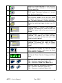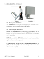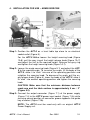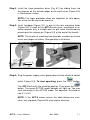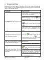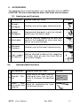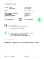
1
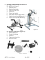
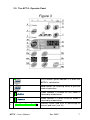
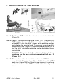
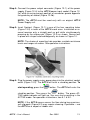
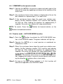
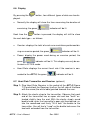
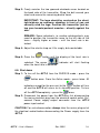
APTAPT-5
USER’S MANUAL
APT-5 – User’s Manual
Rev. 0502
2
Table of contents:
Page
1.
Introduction
5
2.
System components
6
3.
Preparing the APT-5 Hi-Lo
9
4.
Installation for use – Arms exercise
10
5.
Installation for use - Legs exercise
12
6.
Operation instructions
14
7.
General Maintenance & Storage
19
8.
Trouble shooting
20
9.
Accessories
21
10. Technical Data
22
NOTE: Design details may change without notice
APT-5 – User’s Manual
Rev. 0502
3
APT-5 – User’s Manual
Rev. 0502
4
1. INTRODUCTION
The APT-5 is an electric exercise machine used for the improvement of
physical abilities. The APT-5 provides the user with a variety of exercise
options and modes of operation that meet a broad range of physical
needs.
A wide range of accessories are available that offer many exercise options and make the APT-5 suitable for the maintenance of fitness and
physical well being.
The APT-5 can be operated in either the ACTIVE mode at varying degrees of resistance or in the PASSIVE mode at adjustable speed and
torque levels. In the PASSIVE mode it is also possible to combine PASSIVE with ACTIVE training by using physical effort in conjunction with the
electrical operation of the motor. The APT-5 functions forwards or backwards and is suitable for arm or leg exercises (upper or lower limbs). In
case the user has limited strength in the arm, it is recommended to have
an attendant present during exercise.
The APT-5’s light weight makes it portable, easy to store and convenient
to use in the comfort of one’s home. The unit is also suitable for use in
healthcare institutions.
Use of the APT-5 is recommended for the maintenance of muscle
strength, flexibility, muscle tone, endurance and general fitness for users
of all ages.
APT-5 – User’s Manual
Rev. 0502
5
2. SYSTEM COMPONENTS AND DETAILS
2.1. APT-5 unit (Figure 1)
1. Operator panel
2. Angle release knob
3. Angle securing knob
4. Crank-arm
5. Power input socket
6. Heart Rate receiver input socket
7. Height release knob (Hi-Lo only)
8. Height securing knob (Hi-Lo only)
2.2.
1.
2.
3.
4.
5.
Primary components (Figure 2):
Power supply unit
Straight hand-grips
Footrests
Finger protection disks
Securing straps
APT-5 – User’s Manual
Rev. 0502
6
2.3. The APT-5 - Operator Panel
1
On/Off button: green indicator is lit when the
APT-5 is switched on.
2
Mode button: for selecting active or passive
mode of operation.
3
Green indicator is lit when ACTIVE mode is
selected by mode button.
4
Green indicator is lit when PASSIVE mode is
selected by mode button.
5
10%
25%
50%
APT-5 – User’s Manual
75%
100%
Indicates actual load level as percentage of
chosen load level (see 16).
Rev. 0502
7
6
7
Button for forward operation in the PASSIVE
mode. The green indicator is lit to indicate
forward operation.
Button for backward operation in the PASSIVE mode. The green indicator is lit to indicate backward operation.
8
Button activating Auto-Reverse function in
the PASSIVE mode. In the ACTIVE mode
this button activates the constant force function. The green indicator is lit when activated.
9
Button for selecting display of data, (see 1013):
10
Green indicator is lit when Timer display is
selected. The display will show the time the
APT-5 has been used in the current exercise
period.
11
Green indicator is lit when Counter display is
selected. The display will show the total
amount of revolutions of the crank arm in the
current exercise period.
12
Green indicator is lit when Power display is
selected. The display will show the power
during exercise in Watts – only in Active
mode.
13
Green indicator is lit when heart rate display
is selected. The display will show the current
heart rate per minute – only when the Heart
Rate receiver is plugged in.
14
Display for Timer, Counter, Energy and Heart
Rate.
15
Exercise speed level selection push buttons
15a – Increases speed level (up to 10)
15b – Decreases speed level (down to 1)
16
Exercise load level selection push buttons
16a – Increases load level (up to 10)
16b – Decreases load level (down to 1)
APT-5 – User’s Manual
Rev. 0502
8
3. PREPARING THE APT-5 HI-LO
3.1. Moving your APT-5 Hi-Lo
The APT-5 Hi-Lo can easily be moved by lifting the end of the frame
and pushing the unit using its wheels, see Figure 4.
3.2. Positioning the APT-5 Hi-Lo
Position the APT-5 Hi-Lo close to an electrical socket outlet. The adjustable feet on the underside keep the APT-5 Hi-Lo level and prevent it from sliding.
NOTE: Ensure that the APT-5 Hi-Lo is level in order to prevent damage to the trainer or its components.
If readjustment of one of the feet is needed, open the contra nut
(4A/1), turn the foot (4A/2) to the desired height and secure the foot
with the contra nut (4A/1).
APT-5 – User’s Manual
Rev. 0502
9
4. INSTALLATION FOR USE – ARMS EXERCISE
Step 1: Position the APT-5 on a level table top close to an electrical
socket outlet (Figure 5).
For the APT-5 Hi-Lo: loosen the height securing knob (Figure
1A-8), pull the grey ring of the height release knob (Figure 1A-7)
and adjust the unit to the required height. Release the grey ring
and tighten the height securing knob (Figure 1A-7).
Step 2: Loosen the angle-securing knob (Figure 5-1) and adjust the APT5 to the required angle. To increase the angle, lift the body of the
APT-5, allow it to “click” into one of the operating positions and
retighten the securing knob. To decrease the angle, pull the angle release knob (Figure 6), lower the body of the APT-5, allow it
to “click” into another operating position and tighten the securing
knob.
CAUTION: Make sure that the minimum distance between
crank arm and the table surface is approximately 5 cm. / 2”
(Figure 5-2).
Step 3: Connect the output connector (Figure 7-1) of the power supply
(Figure 7-4) to the APT-5 power input socket (Figure 7-2a) while
ensuring correct position of connector groove opposite the guide
key of socket (Figure 7-2b).
NOTE: The APT-5 must be used only with an original APT-5
Power Supply unit.
APT-5 – User’s Manual
Rev. 0502
10
Step 4: Install the finger protection discs (Fig. 8-1) by sliding them into
the grooves on the outside edges of the crank arms (Figure 8-2)
in the direction shown.
NOTE: The finger protection discs are important for safe operation of the unit during hands exercise.
Step 5: Insert handgrip (Figure 9-1) in one of the four mounting holes
(Figure 9-2) in each of the APT-5 crank arms. Installation or removal requires only a straight push or pull while simultaneously
pressing on the release pin (Figure 9-3) at the end of the handle.
NOTE: The choice of mounting hole provides variable resistance
levels and ranges of motion. See operation instructions.
3
Step 6: Plug the power supply mains power plug into the electrical socket
outlet (Figure 5-3). To start operating, press the
button.
The APT-5 will enter the stand-by position. Then press the
button. The green ACTIVE mode indicator will light up. You may
start exercising in the ACTIVE mode. For operation instructions,
see 5.1 & 5.2.
NOTE: If the APT-5 moves across the table during arm exercises, anti-slip pads (Figure 8-3) may require cleaning.
APT-5 – User’s Manual
Rev. 0502
11
5. INSTALLATION FOR USE – LEG EXERCISE
Step 1: Position the APT-5 on the floor close to an electrical socket outlet
(Figure 10).
Step 2: Loosen the angle-securing knob (Figure 10-1) and adjust the
APT-5 to the required angle. To increase the angle, lift the body
of the APT-5, allow it to “click” into one of the operating positions
and retighten the securing knob. To decrease the angle, pull the
angle release knob (Figure 11), lower the body of the APT-5, allow it to “click” into another operating position and tighten the securing knob.
CAUTION: Make sure that the minimum distance between
crank arm and the floor surface is approximately 5 cm. / 2”
(Figure 10-2)
Step 3: Place a chair at the desired distance from the APT-5. If necessary, attach the Securing straps (Figure 10-6) between the APT-5
base rings (Figure 10-5) and the chair legs to prevent any change
in distance between the APT-5 and the chair during leg exercises.
APT-5 – User’s Manual
Rev. 0502
12
Step 4: Connect the power output connector (Figure 12-1) of the power
supply (Figure 12-4) to the APT-5 power input socket (Figure 122a) while ensuring correct position of connector groove opposite
the guide key of socket (Figure 12-2b).
NOTE: The APT-5 must be used only with an original APT-5
Power Supply unit.
Step 5: Insert Footrest (Figure 13-1) in one of the four mounting holes
(Figure 13-2) in each of the APT-5 crank arms. Installation or removal requires only a straight push or pull while simultaneously
pressing on the release pin (Figure 13-3) as shown. Secure feet
in place with straps fastened diagonally as shown in Figure 10.
NOTE: The choice of mounting hole provides variable resistance
levels and ranges of motion. See operation instructions.
Step 6: Plug the power supply mains power plug into the electrical socket
outlet (Figure 10-3). The APT-5 will enter a stand-by position. To
start operating, press the
button. The APT-5 will enter the
stand-by position. Then press the
button. The green ACTIVE mode indicator will light up. You may start exercising in the
ACTIVE mode. For operation instructions, see 5.1 & 5.2.
NOTE: If the APT-5 moves across the floor during leg exercises,
anti-slip pads (Figure 8-3) may require cleaning. If possible – use
the APT-5 on a carpet or rubber mat.
APT-5 – User’s Manual
Rev. 0502
13
6. OPERATION INSTRUCTIONS
NOTE: Install APT-5 for arms or legs exercise as described in the previous chapters.
6.1. Active mode - ISOKINETIC operation
Step 1: Insert the handgrips or footrests in one of the four mounting
holes according to the radius and range of motion required.
NOTE: As the effective crank arm length is reduced in the ACTIVE
mode, the amount of effort required increases while the range of motion decreases, and vice versa.
Step 2: To activate the active mode from the stand-by position (after
the electrical power is supplied to the APT-5 and the
button is pressed): press the
TIVE mode indicator will light up.
button. The green AC-
Step 3: Set the desired load level by pressing one of the selection
push buttons,
crease the level.
to increase the level or
to de-
Step 4: Rotate the APT-5 handgrips or footrests forward or backward. Actual exercising force is displayed as a percentage
(%) on the Bar Indicator.
NOTE: In this mode, an increase in the rotation speed (RPM) will lead
to an increase in the exercising force.
6.2. Active mode - CONSTANT FORCE Operation
Step 1: Press the
button to activate the CONSTANT FORCE
FUNCTION in the ACTIVE mode. The green indicator will
light up.
Step 2: Set the desired load level by pressing one of the selection
push buttons,
crease the level.
to increase the level or
to de-
Step 3: Rotate the APT-5 handgrips or footrests forward or backwards. The exercising force as displayed on the Bar Indicator
will now remain constant at 50% for the selected load level,
irrespective of the crank arm rotation speed.
APT-5 – User’s Manual
Rev. 0502
14
6.3. PASSIVE mode
Step 1: Insert the handgrips or footrests in one of the four mounting
holes according to the radius and range of motion required.
NOTE: As the effective crank arm length is reduced in the PASSIVE
mode, the range of movement is reduced and the degree of resistance that the motor can overcome is increased.
Step 2: To activate the passive mode from the stand-by position (after the electrical power is supplied to the APT-5 and the
button is pressed): press the
button two times,
until the green PASSIVE mode indicator will light up. From
the ACTIVE mode – press once only.
Step 3: Set the desired rotation speed by pressing one of the speed
level push buttons and the desired force by pressing one of
the force load push buttons:
level,
and
and
to increase
to decrease level.
Step 4: Hold onto the handgrips (for arm exercise) or secure both
feet to the footrests (for legs exercise). Make sure that APT-5
is placed at a comfortable distance for exercise by turning the
crank arms one complete revolution.
Press the
button for forward rotation.
Press the
button for backward rotation.
NOTE: There will be a short delay before the APT-5 begins to turn in
the chosen direction.
Step 5: The operation force of the crank arms should rotate the arms
or legs of with no effort on the part of the user. This rotation
force varies according to exercise level and crank arm
mounting hole location selected.
Step 6: To stop the rotation of the crank-arms and exit the PASSIVE
mode, press the
button. The indicators will turn off and
the APT-5 will return to the stand-by position.
APT-5 – User’s Manual
Rev. 0502
15
6.4. COMBINED active/passive mode
Step 1: Operate the APT-5 in the passive mode and work against the
force of the motor by applying resistance to the rotation of the
crank arms.
Step 2: The resistance force to the rotation is displayed on the on the
Bar Indicator as a percentage (%) at each level.
Step 3: If the resistance force stops the crank arm rotation completely, the Bar Indicator reaches 100% and the red indicator
will light up. After holding this position for approximately 2
seconds, the crank arm rotation will stop automatically.
NOTE: To restart, Press the
button for forward rotation, or the
button for backward rotation.
6.5. Passive mode – AUTO-REVERSE function
button to activate the AUTO-REVERSE funcStep 1: Push the
tion in the PASSIVE mode. The green indicator will light up.
Step 2: Operate the APT-5 as in usual passive or combined active/passive mode.
Step 3: When the resistance force stops the crank arm rotation completely, the Bar Indicator reaches 100% and the red indicator
will light up. After holding this position for approximately 2
seconds, the crank arm rotation will stop automatically. After
a short delay the DIRECTION OF ROTATION WILL BE REVERSED. This feature also serves as an ANTI-SPASM function, stopping the motor in case of muscle spasm and reversing the direction of rotation after a short delay.
Step 4: As long as the
button indicator is lit, this function will
continue to operate in the PASSIVE mode.
APT-5 – User’s Manual
Rev. 0502
16
6.6. Display
By pressing the
button, four different types of data can be dis-
played.
•
Normally the display will show the time measuring the duration of
exercising; the green
Each time the
indicator will be lit.
button is pressed, the display will shift to show
the next data type – as follows:
•
Counter: displays the total of crank arm revolutions performed duindicator will be lit.
ring an exercise period; the green
•
Power: display the power used during an exercise period; the
green
indicator will be lit. This display can only be ac-
tivated in ACTIVE mode.
•
Heart Rate: displays the current heart rate if the receiver is connected to the APT-5; the green
indicator will be lit.
6.7. Heart Rate Transmitter and Receiver (optional)
Step 1: Plug Heart Rate Receiver in the socket of the APT-5 (Figure
7-3) and attach the Receiver itself on the left side of the base
with the arrow (the white lable) pointed towards the user.
Step 2: Attach the elastic strap to the transmitter. Observe that each
end of the transmitter has an open slot and two "teeth" extended slightly from the end. With the elastic strap's round
buckle head, enter the transmitter's open slot from behind, rotate the roundhead and firmly "lift & lock" the buckle to the
transmitter. You will feel a "snap" as the buckle locks over the
two teeth extended from the transmitter.
APT-5 – User’s Manual
Rev. 0502
17
Step 3: Freely moisten the two grooved electrode areas located on
the back side of the transmitter. Wrap the belt around your
chest and secure the remaining buckle head.
IMPORTANT: The logo should be centered on the chest,
right-side-up so someone standing in front of you can
correctly read the logo. Position the transmitter just below your breasts/pectoral muscles – directly against the
skin.
REMARK: Some individuals, i.e. cardiac rehab patients, may
need to position the transmitter more to the left side of the
torso – slightly higher or lower – until the heart rate is detected.
Step 4: Adjust the elastic strap so it fits snugly, but comfortable.
Step 5: Press the
button until the display of the heart rate is
selected. The green
indicator will start flashing
when the heart rate is detected.
6.8. Shut down
Step 1: To turn off the APT-5, from the PASSIVE mode – press the
button once. From the Active mode – press twice. All
indicators except for the one next to the
button will turn
off and the APT-5 will return to its stand-by position. To turn
off the APT-5 completely – press the
once.
Step 2: Disconnect the power from the APT-5 by first disconnecting
the mains electrical plug from the electrical socket outlet. Disconnect Power supply output connector from the APT-5
power input socket.
CAUTION: For safe disconnection always take the mains plug out of
the electrical socket before disconnecting the Power supply from the
APT-5.
APT-5 – User’s Manual
Rev. 0502
18
7. GENERAL MAINTENANCE & STORAGE
The rugged design of the APT-5 and the use of selected, modern materials ensure minimal requirements for care and maintenance. The APT-5
can be lifted safely in its folded position by grasping on to the center of either of the legs of the base and carrying like a suitcase.
NOTE: Improper handling or neglect in the care of the APT-5 may reduce
or cancel the coverage of the manufacturer’s warranty.
7.1. Regular care
•
•
•
•
Inspect Power supply cables and plug for visible damages.
Check power-input connector for visible damage or insecure fastening.
On a regular basis check that all screws and components are fastened tightly.
Ensure that the anti-slip pads under the base are always kept
clean.
CAUTION: If any damage is detected – do not use the APT-5.
Please contact your authorized dealer. Only authorized personnel may carry out repairs.
7.2. Cleaning instructions
•
Disconnect Power Supply and wipe dry with clean cloth.
CAUTION: For safe disconnection of the APT-5 always take the
mains plug out of the wall socket before removing the connector
from the APT-5 power socket.
•
Take care not to allow water to enter the unit. Keep cables and
electric components away from water and humidity.
7.3. Storage
•
•
Store the APT-5 between –20 and +40 degrees C and between
10% and 80% humidity.
For storage in a confined space, fold the APT-5 unit by pulling
the angle release knob (Figure 1-2) and lowering it to the flat position. Tighten the angle-securing knob (Figure 1-3) to prevent
unintentional unfolding.
APT-5 – User’s Manual
Rev. 0502
19
8. TROUBLE-SHOOTING
Hereunder are some types of disorders, which can usually be repaired
rather simply. If these following measures are unsuccessful, an authorized
dealer should be contacted!
PROBLEM
CHECK POINT
Power Supply not connected properly to
mains outlet or to the APT-5.
APT-5 switched off. Press the
but-
ton to turn APT-5 on.
The APT-5 does not function at all
APT-5 in stand-by mode. Press the
button to enter active or passive
modes.
Stop switch in lower - disconnection position. Turn switch anti-clockwise to release.
No direction selection button is selected.
The crank-arms do not start to ro- Press the
button (Figure 3-6) for
tate in the passive mode
forward rotation. Press the
button
(Figure 3-7) for backward rotation
Model with remote control: remote
Remote unit’s transmitter LED needs to
be wiped clean.
unit not functioning smoothly
Remote unit batteries need replacement.
Correct display not selected: press the
button until the LED next to the
heart lights up.
Model with Heart Rate Transmit- HR Receiver not plugged in or pointed in
ter and Receiver: heart rate is not the right direction: check connection and
displayed
ensure that the Receiver is pointed towards the user (the pointed white lable).
Heart Rate Transmitter not applied properly on the body of the user.
APT-5 – User’s Manual
Rev. 0502
20
9. ACCESSORIES
The following items are designed for use in combination with the APT-5.
CAUTION: The use of accessories other than these can be unsafe.
9.1. Hand grips and Footrests
# ACCESSORY
USAGE DESCRIPTION
FIGURE
a)
Straight
Handgrips
Used for most of the upper limb exercising.
b)
Angled
Handgrips
Ergonomically designed, mainly for strength
exercising in the Active mode.
c) Hemi-glove
Used for securely supporting the wrist and
hand on the handgrips for users who have
little or no muscle strength.
d)
Standard
Footrests
Used for most of the lower limb exercising.
e)
High support
for footrests
May be attached to footrests for supporting
the lower limbs of users that have little or
no muscle strength.
9.2.
#
Optional added functions
ACCESSORY
Remote
a)
trol
Con-
Heart
Rate
b) transmitter and
receiver
APT-5 – User’s Manual
USAGE DESCRIPTION
FIGURE
Used mainly for lower limb exercising by users who have difficulty in reaching the operating
panel.
Used for monitoring the heart
rate during exercise
Rev. 0502
21
10. TECHNICAL DATA
Weight - Trainer
- Power supply
Length
Width
Height
Mains supply (to Power Unit)
Working voltage
Revolutions per minute
Power consumption
10 Kg. (22 lbs.)
1.4 Kg. (3lbs.)
72 cm. (28 in.) overall
46 cm. (18 in.)
16 cm. (6½ in.) folded
110/230 VAC
18 VAC
20 - 60 RPM
60 VA
Class II equipment
Type B equipment
Class of protection: II
• No protective (earthed) conductor
• No protective earth terminal
Degree of protection at the applied part: Earth potential
• Not insulated against earthed parts
• Not suitable for direct cardiac application
Continuous operation
Equipment not suitable for use in the presence of flammable anaesthetic
mixture with air or with oxygen or nitrous oxide.
APT-5 – User’s Manual
Rev. 0502
22
For safety and for warranty assurance reasons, any modifications and repair of the APT-5 or its components must be performed exclusively by authorized personnel and exclusively with original spare parts.
The APT-5 and its accessories have been designed and manufactured in
accordance with the specification of the following:
DIRECTIVE: Medical devices 93/42 EEC (Annex V)
Tzora Active Systems Ltd.
15 Avraham Giron st.
Manufactured by:
Industrial zone Yahud
56217 Israel POB 217
Tel. +972-3-5398999
Fax. +972-3-6320879
Distributed in USA by: Lifestyle Sports 10247 Lakeside Blvd Ext, Dunkirk, NY 14048
1-800-666-9198 716-679-7716 Fax 716-679-7718 [email protected] APT-trainers.com
APT-5 – User’s Manual
Rev. 0502
23