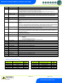
1
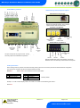
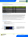
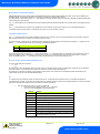
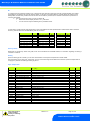
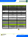
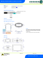
Mercury PR0710-MOB PR0720-MOB Intuitive PR0750-MOB PR0760-MOB Mercury 2 & Intuitive Mercury Mobile Controller Installation & User Guide For Products: - PR0710, PR0711, PR0720, PR0721 Resource Data Management UK OFFICE Resource Data Management Ltd 80 Johnstone Avenue, Hillington Industrial Estate, Glasgow, Scotland, G52 4NZ, UK +44(0)141 810 2828 [email protected] US OFFICE Resource Data Management Inc 100 North Sixth Street, Suite 630B, Minneapolis, MN 55403, USA Tel +1 612 354 2923 [email protected] Mercury 2 & Intuitive Mobile Controller User Guide Table of Contents: ............................................................................................................................................................................. 1 THE MERCURY & INTUITIVE RANGE .............................................................................................................. 4 Variants ............................................................................................................................................................ 4 Compatible Displays ........................................................................................................................................ 4 Configuration ..................................................................................................................................................... 4 Compatible Network Interfaces ........................................................................................................................ 4 Front Display Features ...................................................................................................................................... 5 Connections ....................................................................................................................................................... 5 Mercury Mk2 6-5E and 6-5M ............................................................................................................................. 5 Intuitive Mercury Controller .............................................................................................................................. 6 Ordering Information ........................................................................................................................................ 6 Input and Output Allocation Tables ................................................................................................................. 7 Input / Output allocation table .......................................................................................................................... 7 Switched Resistor Values ................................................................................................................................ 7 Setting up the controller ................................................................................................................................... 7 Setup through front buttons ............................................................................................................................. 7 Setup Function Menu ....................................................................................................................................... 8 Recommended set-up method ......................................................................................................................... 8 rtc. Real time clock (This will automatically synchronise on network systems) ............................................... 8 type. Set/view controller type ........................................................................................................................... 8 PArA. Set/view parameters (This can be achieved at the network front end) ................................................. 8 Unit. Set/view temperature unit and Probe type .............................................................................................. 8 Display.............................................................................................................................................................. 9 Parameter Tables ............................................................................................................................................... 9 Parameter Descriptions .................................................................................................................................. 10 Relay State and functional operation ............................................................................................................ 12 Relay and screen states during defrost ........................................................................................................ 13 Defrost Type (P-91)........................................................................................................................................ 13 Defrost Termination........................................................................................................................................ 13 Fan Delay after Defrost .................................................................................................................................. 13 Network Configuration .................................................................................................................................... 13 RS485 Legacy module / Intuitive Internal RS485 Network card .................................................................... 13 Wireless Mesh Communication Module ......................................................................................................... 14 Fast Network Address Reset ......................................................................................................................... 14 IP Futura module / Intuitive Internal IP Network card .................................................................................... 14 Mercury Switch ................................................................................................................................................ 15 Viewing ............................................................................................................................................................. 15 Input / Output Table ....................................................................................................................................... 15 Maximum and Minimum Control Temperature............................................................................................... 16 Messages .......................................................................................................................................................... 16 Network Alarms ............................................................................................................................................... 16 Modifying controller states ............................................................................................................................. 16 Fans Only “FAnS” .......................................................................................................................................... 17 Case Off “CASE” ............................................................................................................................................ 17 Lights Only “Ligt” ............................................................................................................................................ 17 Probe Offset ................................................................................................................................................... 17 Remote Commands ......................................................................................................................................... 17 Power requirements ....................................................................................................................................... 18 General........................................................................................................................................................... 18 Relay Specification ......................................................................................................................................... 18 Specification .................................................................................................................................................... 18 Inputs.............................................................................................................................................................. 19 Switched Resistor Example Wiring ............................................................................................................... 19 Installation ........................................................................................................................................................ 19 Warning Ensure that all power is switched off before installing or maintaining this product Revision 1.2 Page 2 of 21 www.resourcedm.com Please Note Mercury 2 & Intuitive Mobile Controller User Guide Fixing .............................................................................................................................................................. 19 Dimensions ...................................................................................................................................................... 19 Dimensions ...................................................................................................................................................... 20 Intuitive Mercury Mounting Instructions ......................................................................................................... 20 Cleaning ......................................................................................................................................................... 20 Disclaimer ......................................................................................................................................................... 20 Revision History .............................................................................................................................................. 21 Warning Ensure that all power is switched off before installing or maintaining this product Revision 1.2 Page 3 of 21 www.resourcedm.com Please Note Mercury 2 & Intuitive Mobile Controller User Guide The Mercury & Intuitive Range From Resource Data Management For Version Mob 1.0 The Mercury Mk2 Mobile controller is intended for use in refrigeration display cabinets with one or two integral compressors with each compressor having a temperature probe fitted to enable the compressor to be stopped if a set (discharge) temperature is exceeded. The controller will switch on one or two compressors based on the average of an air on and air off temperature probes and has outputs to control lights, fans and defrost control. The lighting relay can be set to operate as an alarm relay if required. The controller also has an inbuilt defrost timer and 7 day lighting control timer which can also be used to switch the cabinet off and on at specific times, this can be a useful energy saving feature if the cabinet contains non perishable goods (such as drinks) and can be automatically switched off at night. There is also a DIN rail mounted version, known as the Intuitive Mercury, which is designed to be used in a control panel or electrical tray. This range has the same features as the Mercury Mk2 controller with additional benefits such as higher rated relays, each protected by an integral fuse and fuse protection for the incoming power supply. All connections are plug in socket and there are multiple network interfaces to choose from including Ethernet. The controller supports PT1000, NTC2K, 470R, 700R, 3K, 5K, 6K, NTC2K25, NTC10K or NTC10K(2) temperature probes (note: probe types cannot be mixed) Variants Description Mercury Mk2 Single or Twin Compressor Controller, integral display. Mercury Mk2 Single or Twin Compressor Controller, remote display. Intuitive Mercury Single or Twin Compressor Controller, integral display. Intuitive Mercury Single or Twin Compressor Controller, remote display. Intuitive Mercury Single or Twin Compressor Controller, integral display, built in IP network card. Intuitive Mercury Single or Twin Compressor Controller, remote display, built in IP network card. Part Number PR0710-MOB PR0720-MOB PR0750-MOB PR0760-MOB PR0750-MOB-IP PR0760-MOB-IP Compatible Displays The following displays are compatible with the Mercury / Intuitive Remote Display Controllers (PR0720 & PR0760): Description Mercury Remote Display with 5m cable Mercury Keyswitch Remote Display with 5m cable Mercury DIN Remote Display with 5m cable Mercury DIN Keyswitch Remote Display with 5m cable Mercury mk2 Remote Display with 5m cable Part Number PR0325 PR0326 PR0327 PR0328 PR0725 Configuration The controller gives you two configuration options: Display value 1 2 Type Integral controller HT Integral controller LT The controller is delivered pre-configured as type 1. Compatible Network Interfaces Mercury and Intuitive Mercury controllers are capable of connecting to either a TCP/IP local area network, an RS485 Genus compatible network, an RDM wireless mesh network or they can be used in standalone mode with no network output. To connect to a network you must add the correct communications module. Connecting to any of these communication modules will automatically be detected on power up and will affect the set up screens available to you. Description IP Futura (Single Mercury to IP Interface) RS485 Interface (Single Mercury to RS485 Interface) Mercury IP Switch (IP support for 10 controllers) Mercury IP Switch with Pressure/Humidity Inputs Wireless Mesh Interface (for single Mercury) Part Number PR0016 PR0026 PR0018 PR0018-PHI PR0730 The Intuitive Mercury Controller is supplied as standard with an internal RS232 network card, this allows connection to any of the above external network interfaces. Three alternative internal network cards are also available, these can be supplied factory fitted as an option or purchased separately as an interface kit. Warning Ensure that all power is switched off before installing or maintaining this product Revision 1.2 Page 4 of 21 www.resourcedm.com Please Note Mercury 2 & Intuitive Mobile Controller User Guide Description Intuitive Internal IP Network Card Interface Kit Intuitive Internal RS485 Network Card Interface Kit Intuitive Internal Wireless Mesh Network Card Interface Kit Part Number PR0770 PR0771 PR0772 Front Display Features LED’s: Cooling (Relay 1 or 4) Fans (Relay 2) Lights (Relay 3) Defrost (Relay 5) Keys On-Line Off No network attached Flashing Attempting to Log on to network Steady On-line Enter Up Down Defrost Note: Function keys illuminate when pressed, illumination is turned off 20 seconds after the key is used. Press and hold the defrost button to force a manual defrost Service (See Parameter 18 for setup) Alarm Main Display HACCP 4 character LED display, used to display temperature and status messages. Note the Intuitive Mercury display is Green in colour when lit. Connections Mercury Mk2 6-5E and 6-5M Not Used Fans Common Fans Out Not Used Compressor A Out Compressor A Common Not Used Air On Probe Air Off Probe Comp A Disch. Comp B Disch. Defrost Probe Logging Probe Input and Output connections are made to the back of the controller, the RS232 communication port is on the side. The diagram shows the connection detail. Relay Connections Supply Neutral Supply Live Defrost Mains Out Not Used Compressor B Common Compressor B Out Lights/ Alarm Out Not Used Light / Alarm Common Probe Commons Temperature Probe Connections Warning Ensure that all power is switched off before installing or maintaining this product Revision 1.2 Page 5 of 21 www.resourcedm.com Please Note Mercury 2 & Intuitive Mobile Controller User Guide Intuitive Mercury Controller Common Compressor B Out Not Used Common Defrost Out Not Used Logging Probe Common Defrost Probe Common Comp B Disch. Common Comp A Disch. Common Air Off Probe Common Air On Probe Common Intuitive Mercury Network Expansion Options RS232 Network Card (Default) The Intuitive Mercury is supplied with an RS232 Network Card fitted as standard. Some example optional network cards are shown below IP Network Card (PR0770) Rotary Address Switches Network Collision LED Network Activity LED Compressor A Out Not Used Common Fans Out Not Used Common Mains Supply 100-240vAC 50-60Hz Lights /Alarm Out Not Used Common N N/C L RS485 Network Card (PR0771) Network Expansion Port Network Activity LED All inputs and outputs are plug and socket. The supply voltage and relay outputs have individual fuse protection. A+ BGround Ground Screen PR0772 Wireless Mesh Option also available. The network interfaces work in the same way as there external counterparts. Ordering Information When ordering a Mercury Intuitive controller the following ordering scheme can be used to purchase the desired hardware configuration. This ensures the controller ships with the optional hardware pre-fitted. PR07X0-Y X 5 6 Where X and Y and are selections from the tables below. Description Internal Display Remote Display Y IP RS485 Description RS232* IP Interface RS485 Interface * Fitted by default. Example – To order a remote display variant, with a built in IP module use the following part number: PR0760-IP Warning Ensure that all power is switched off before installing or maintaining this product Revision 1.2 Page 6 of 21 www.resourcedm.com Please Note Mercury 2 & Intuitive Mobile Controller User Guide Input and Output Allocation Tables The following tables indicate; on a controller type basis, the functions of the inputs and outputs. Also shown are the digital inputs that are derived by switching in a fixed value resistor across the input. Input / Output allocation table TYPE Input 1 Input 2 Input 3 Input 4 Input 5 Input 6 Relay 1 Relay 2 Relay 3 Relay 4 Relay 5 Integral Case Types 1&2 Air on Temperature Air off Temperature Compressor A Discharge Temperature Compressor B Discharge Temperature Defrost Termination or Monitor probe (if used) Logging Probe (If fitted) Compressor A Fans Lights/Alarm Relay Compressor B Defrost Heater Alarm Action Yes Yes Yes Yes Conditional* Conditional* N/A N/A N/A N/A N/A Plant Input (Switched Resistors) Plant fault 1 or External Defrost Input ** Case Clean Switch Plant fault 2 * Alarm on monitor probe only if used ** Defrost type must be set to remote in parameters. Switched Resistor Values For PT1000 probes use 820 Ohm switched resistors. For NTC2K, NTC2K25 and 3K probes use 590 Ohm switched resistors. For 5K and 6K use 1K Ohm switched resistors. For NTC10K probes use 2k7 Ohm switched resistors. For NTC10K(2) probes use 2k2 Ohm switched resistors. The resistors used must have a tolerance of 1% or better and the resistor must have a power rating of 0.25W. For improved accuracy whilst using switched resistors RDM recommend resistors with 0.1% accuracy are used. Note the switched resistor features will not function when using 470R or 700R probes. When a resistor is switched across the appropriate input it signals to the Mercury to enable the switched resistor function described for that input whilst still recording the probe temperature on the input. Temperature range for all probe types is -49oC to +127oC for probe inputs which do not have a secondary function (switched resistors). Inputs which have a secondary function are restricted to -42oC to +60oC. If the full temperature range is required on all inputs and no switch resistor features are needed then please see Switch Resistor parameter P-19 Note: switched resistors will operate in LT (Low Temperature) and HT (High Temperature) applications using PT1000, NTC2K or NTC2K25 probe types only. For all other probe types the switched resistor inputs will work in HT applications only. Setting up the controller Access to the controller can be achieved several ways Through the front mounted buttons Direct access by PC into the side comms port. This requires the Communicator software package available free on the RDM website Through legacy front end panels on 485 networks Through the RDM Data Manager. Across an IP network. (Current controller IP address required) Setup through front buttons ENTER DEFROST UP DOWN To enter setup mode, hold the Enter and Down buttons together for approximately 3 seconds until the message “Ent” appears on the display. Now press the Enter button again to enter the function menu. IO will be displayed. Scroll up or down to go through the list. Warning Ensure that all power is switched off before installing or maintaining this product Revision 1.2 Page 7 of 21 www.resourcedm.com Please Note Mercury 2 & Intuitive Mobile Controller User Guide Setup Function Menu Display IO PArA Unit diSP tyPE rtc Option View Inputs / Outputs and States Set/View Parameters Probe type and Celsius/Fahrenheit option Display whole units or decimal Set/View Controller Type Set/view Clock (rtc = Real Time Clock) Explained in Paragraph Input / output table Display Explained in Paragraph Network Configuration Option nEt Set/view network configuration Set view parameters SoFt View software version Set View Unit FANS Toggle Fans Only mode Fans Display CASE Toggle Case Off mode Case Off Ligt Toggle Lights Only mode OFSt Probe Offset ESC Exit Setup mode Set/view controller type Real Time Clock Lights Probe Offset Recommended set-up method If you are not connecting to a network and want to set up the controller through the buttons we recommend you use the following order from the function menu. rtc. Real time clock (This will automatically synchronise on network systems) a. Use the up or down buttons to scroll through the display until the display reads “rtc” b. Press enter. The display will show “t-1”. press enter again c. Scroll hours up or down (0 – 23) press enter d. Use up button to select “t-2”, press enter e. Scroll minutes up or down (0 – 59) press enter f. Repeat for t-3 (seconds 0 – 59) g. Repeat for t -4 (Days up to 31) h. Repeat for t -5 (months up to 12) i. Repeat for t -6 (Year up to 99) j. Use up button to display “ESC”, press enter to display “rtc” Time clock is now set type. Set/view controller type a. From the function menu scroll to select type, press enter b. Use the up/down buttons to scroll through HT/LT configuration types. (see configuration table on page 4) c. Press enter. d. Scroll to select “ESC” e. Press enter Controller type configuration is now set PArA. Set/view parameters (This can be achieved at the network front end) a. From the function menu scroll to select PArA b. Pressing Enter while PArA is displayed will enter the parameter menu. The first parameter option will be displayed as P01. Pressing the Up or Down button will present the other parameter options P-02, P-03 etc. See the parameter list below to find what parameter number corresponds to which actual parameter. Pressing the Enter button will show the current value of the selected parameter. Press Up or Down to modify the value and press Enter again to save the value. The parameter list number will be displayed again. Two other options are present in the parameter menu – dFLt and ESC. Selecting ESC will exit setup mode. Selecting dFLt will reset all parameters back to the default values for the current type of controller. Unit. Set/view temperature unit and Probe type From the function menu scroll to select Unit Press enter and the value will be displayed: Probe Types 0 for PT1000 Celsius 1 for PT1000 Fahrenheit 2 for NTC2K Celsius 3 for NTC2K Fahrenheit 4 for 470R Celsius 5 for 470R Fahrenheit 6 for 700R Celsius 7 for 700R Fahrenheit 8 for 3K Celsius 9 for 3K Fahrenheit 10 for NTC2K25 Celsius 11 for NTC2K25 Fahrenheit 12 for 5K Celsius 13 for 5K Fahrenheit 14 for 6K Celsius 15 for 6K Fahrenheit 16 for NTC10K Celsius 17 for NTC10K Fahrenheit 18 for NTC10K(2) Celsius (USA NTC10K) 19 for NTC10K(2) Fahrenheit (USA NTC10K) Use the up or down keys to select the units and press enter. This function is now complete Warning Ensure that all power is switched off before installing or maintaining this product Revision 1.2 Page 8 of 21 www.resourcedm.com Please Note Mercury 2 & Intuitive Mobile Controller User Guide Display From the function menu scroll to and select diSP. Press enter and one of the following values will be shown: 0. Controller display will show the whole number and tenths value of a temperature reading. (Default) 1. Controller display will show temperatures as a whole number. Parameter Tables Number Parameter Range Step o C ( oF ) -42 to 30 (-43.6 to 86) 0.1 0 to 10 (0 to 18) 0.1 0 to 100 1 0 to 100 1 00:00 to 15:00 00:05 00:00 to 15:00 00:05 0 to 10 (0 to 18) 0.1 0 = Case Off 1 1 = Fans only 2 = toggle 0 = Use Air on Probe 1 1 = Use Log Probe 0 (Disabled),1(Enabled) 0 = Off 1 1 = Temperature 2 = Over-temperature 3 = Temp/OT -42 to 30 (-43.6 to 86) 0.1 0 = Defrost, 1 = Monitor 1 0 = Lights, 1 = Alarm 1 0 = Plant fault, 1 1 = External defrost 0 to 128 1 P-01 P-02 P-03 P-04 P-05 P-06 P-07 P-85 Cut-in Temp. Cut In Differential Control Weight Display Weight Lag Comp Delay Anti SC Time Lag Cut Out Diff Key-switch Mode P-87 Control Probe type P-90 P-92 Resistor Case Off Fans temperature mode P-93 P-15 P-16 P-29 Fans Off Temperature Probe 5 Select Relay 3 Mode Probe 3 Resistor function P-18 Service Interval time P-19 P-98 Switch Resistors Lights Case Off P-99 Load Shedding P-30 P-31 P-32 P-33 P-34 P-35 Do (enable) Discharge Stop Compressor A Do (enable) Discharge Stop Compressor B Discharge Stop Value Discharge Stop Differential Maximum Compressor Run Time Comp Stop Both P-20 P-21 P-22 P-23 Alarm Delay UT Alarm OT Alarm Log Probe Type P-24 P-25 P-26 P-27 P-28 P-40 Slug Log Probe Log Alarm Delay Log UT Alarm Log OT Alarm Monitor OT Alarm Defrost Mode P-41 P-42 P-43 P-44 Defrost Start Defrosts per Day No Defrost Time Def Terminate Temp. 0 (Off), 1(On) 0 (Off), 1 (On), 2 (Unused) 0 (Off), 1 (Mode 1), 2 (Mode 2) 0 (Off), 1(On) 0 (Off), 1(On) -49 to 128 -42 to 30 00:00 to 99:00 0 = Yes 1 = No 00:00 to 99:00 -49 to 60 (-56.2 to 140) -49 to 60 (-56.2 to 140) 0 (Off), 1 (Logging), 2 (Logging/Alarm) 0 (Off), 1 (On) 00:00 to 99:00 -49 to 60 (-56.2 to 140) -49 to 60 (-56.2 to 140) -49 to 60 (-56.2 to 140) 0 (Local), 1 (Remote), 2 (External) 00:00 to 23:59 0 to 8 0 to 25 -42 to 30 (-43.6 to 86) P-45 Def Min Time 00:00 to 99:00 Units Default LT o C ( oF ) -20 (-4) 2.5 (4.5) 40 40 00:40 07:00 2.5 (4.5) 0 Default HT o C ( oF ) 3.5 (38.3) 2.5 (4.5) 30 30 00:10 07:00 2.5 (4.5) 0 0 0 0 0 0 0 Deg -10 (14) 0 0 0 8 (46.4) 0 0 0 KHrs 60 60 1 0 1 0 0 0 0 0 55 10 00:00 0 0 0 55 10 00:00 0 20:00 -30 (-22) -15 (5) Off 20:00 -2 (28.4) 5 (41) Off Off 20:00 -35 (-31) -12 (10.4) 20 (68) Local Off 20:00 -1 (30.2) 6 (42.8) 20 (68) Local 01:00 6 12 10 (50) 05:00 Deg Deg % % mm:ss mm:ss Deg 1 1 1 0.1 0.1 01:00 1 Deg Deg mm:ss 01:00 0.1 0.1 mm:ss Deg Deg 01:00 0.1 0.1 0.1 mm:ss Deg Deg Deg 00:01 1 1 0.1 hh:mm hours Deg 01:00 6 12 14 (57.2) 01:00 mm:ss 05:00 Warning Ensure that all power is switched off before installing or maintaining this product Revision 1.2 Page 9 of 21 www.resourcedm.com Please Note Mercury 2 & Intuitive Mobile Controller User Guide P-46 P-47 P-48 P-89 P-86 P-49 P-88 P-50 P-91 Def Max Time Drain Down Recovery Time Pump Down Time Fan Delay mode Fan Delay Time Fan Delay Temp Fans In Defrost Defrost Type (Integral) P-94 P-95 P-96 P-60 Defrost Hold Defrost Skip Defrost Skip Time Lights Mode P-61 P-62 P-63 P-64 P-65 P-66 P-67 P-68 P-69 P-70 P-71 P-72 P-73 P-74 dFLt Sun Lights On Sun Lights Off Mon Lights On Mon Lights Off Tue Lights On Tue Lights Off Wed Lights On Wed Lights Off Thu Lights On Thu Lights Off Fri Lights On Fri Lights Off Sat Lights On Sat Lights Off Restore defaults 00:00 to 99:00 00:00 to 24:00 00:00 to 99:00 00:00 to 99:00 0 = Time 1 = Temp 00:00 to 99:00 -42 to 30 (-43.6 to 86) 0 (Off), 1 (On) 0 = Elec. 1 = Gas. 2 = Elec CIn 0 (Off), 1 (On) 0 (Off), 1 (On) 00:00 to 99:00 0 (Local), 1 (Remote), 2 (Man Off), 3(Man On) 00:00 to 23:59 00:00 to 23:59 00:00 to 23:59 00:00 to 23:59 00:00 to 23:59 00:00 to 23:59 00:00 to 23:59 00:00 to 23:59 00:00 to 23:59 00:00 to 23:59 00:00 to 23:59 00:00 to 23:59 00:00 to 23:59 00:00 to 23:59 01:00 00:15 01:00 01:00 1 01:00 0.1 mm:ss mm:ss mm:ss mm:ss mm:ss Deg 01:00 mm:ss 00:01 00:01 00:01 00:01 00:01 00:01 00:01 00:01 00:01 00:01 00:01 00:01 00:01 00:01 hh:mm hh:mm hh:mm hh:mm hh:mm hh:mm hh:mm hh:mm hh:mm hh:mm hh:mm hh:mm hh:mm hh:mm 30:00 01:30 30:00 00:00 0 00:00 -20 (-4) On 0 30:00 00:30 30:00 00:00 0 00:00 0.0 (32) On 0 Off Off 12:00 Local Off Off 12:00 Local 08:00 20:00 08:00 20:00 08:00 20:00 08:00 20:00 08:00 20:00 08:00 20:00 08:00 20:00 08:00 20:00 08:00 20:00 08:00 20:00 08:00 20:00 08:00 20:00 08:00 20:00 08:00 20:00 Parameter Descriptions Number P-01 P-02 Parameter Cut-in Temp Diff P-03 Control Weight P-04 P-05 Display Weight Lag Comp Delay P-06 P-07 Anti SC Time Lag Cut Out Diff P-85 Key-switch Mode P-87 Control Probe type P-90 P-92 Resistor Case Off Fans temperature mode P-93 Fans Off Temperature P-15 Probe 5 Select Description Temperature at which the lead compressor will switch on. Differential temperature below the cut-in temperature. The lead compressor switches off when below this temperature Percentage of the Air-On temperature that is used to calculate the control temp. The remaining percentage will be used on the Air-Off temperature Example, P-03 set to 30% Control temp = 30% Air-on + 70% Air-off As above only applied to the display temperature Delay before the second compressor is switched on if the temperature is still above set-point. Note – The lead and lag compressors swap after each defrost to even the run times. Allows the user to set the compressor for a given number of starts/hour Diff below the Cut-In Temp the lag compressor switches off. Single Compressor Operation To disable compressor B operation and use only a single compressor for control set parameter P-07 to 0. This will allow the controller work with just one compressor (A) and ignore compressor B. Allows the keys switch to be: Single turn for case off (Case off mode) Single turn for Fans only (Fans Mode) Single turn for case off, double turn for fans only (Toggle mode) Switches between using the air-on probe and the Logging probe. Note the control and display temperature will still be a derivative of the weighted Average of the control probe + Air-off probe Turns on/off the switched resistor case off function Allows the user to set the fans to turn off when: A pre-determined temperature is reached (P93) When an over-temperature alarm is present When either P93 is reached or an OT alarm is present Temperature for the above (P92) operation. Note the defrost termination probe is the source of the temperature reading used in this feature. If the defrost termination probe isn’t fitted then a similar process to P-44 is used. This input can be used as a defrost termination probe (default) or as a monitor probe with an OT alarm Warning Ensure that all power is switched off before installing or maintaining this product Revision 1.2 Page 10 of 21 www.resourcedm.com Please Note Mercury 2 & Intuitive Mobile Controller User Guide P-16 Relay 3 mode P-29 Probe 1 or Probe 3 Resistor Service Interval Time (Run Hours) P-18 P-19 Switch Resistors P-98 Lights Case Off P-99 Load Shedding P-30 Do Discharge Stop Compressor A Do Discharge Stop Compressor B Discharge Stop Value P-31 P-32 P-33 P-35 Discharge Stop Differential Maximum Compressor Run Time Comp Stop Both P-20 P-21 P-22 P-23 Alarm Delay UT Alarm OT Alarm Log Probe Type P-24 Slug Log Probe P-25 P-26 P-27 P-28 P-40 Log Alarm Delay Log UT Alarm Log OT Alarm Monitor OT Alarm Defrost Mode P-41 P-42 Defrost Start Defrosts per Day P-43 No Defrost Time P-44 Def Terminate P-45 Def Min Time P-34 level (P-28) This changes the function of relay 3 from Lights (default) to an alarm relay. The alarm relay is energised for no alarm. Use the NC and Common for “Loop make” on alarm or use the NO and Common for “Loop break” on alarm. Selects whether the switched resistor invokes either a Plant fault or an External Defrost. Time (in 1000 x hours) before the service icon (Spanner icon) comes on. The Run Hours timer increments based on the number of hours the controller has been powered up and running. Reset the spanner icon to off by changing this parameter to 0 and then back to the desired service interval. This process also resets the Run Hours value to 0. To view the current Run Time value refer to the I/O list. Enables switched resistors to be used for Plant Faults, External Defrosts, Case Clean. See : Switched Resistor Values Used to place the controller into Case Off when its lighting timer is in the off state. When the lighting timer is in the on state the controller follows its normal control operation. This feature is disabled if the set point (P-01) is below 6oC. Please note that when the controller is in case off all alarms are inhibited and all outputs are turned off. Therefore care must be taken when enabling this parameter. Off – Feature is not used and only the controller lights relay follows the lighting timer status. On - Feature is in use and controller will be in Case Off whenever the lights timer is in the off state. Unused – This selection has no effect and should not be used. Please select from either Off or On. This feature operates in either Local, using controller RTC, or Remote, using Data Manager GP timer channel, lighting applications. Off – Feature is not used Mode 1 – Case goes to “CO2 Load Shedding Case Off Mode” Mode 2 – Goes to Case Clean Mode See: Load Shedding This enables the discharge stop on compressor A, if set to ON then the compressor will be disabled if the discharge temperature is exceeded. This enables the discharge stop on compressor B, if set to ON then the compressor will be disabled if the discharge temperature is exceeded. If a compressor discharge probe exceeds this value and P-30 and P-31 are set to ON then the relevant compressor will be disabled. This is the differential below the discharge stop value that the discharge probe temperature has to drop before the compressor is enabled again. This limits the running time of any compressor, once the compressor has exceeded this time period it will be switched off for the period of the anti short cycle time (P-06) If either compressor stops due to expiry of the Maximum Compressor Run Time then both compressors will be disabled if P-35 is set to On. Delay for the over and under-temperature alarms Under temperature alarm set point. This alarm uses the control temperature. Over temperature alarm set point. This alarm uses the air-off temperature. Allows the user to set the logging probe mode: Off Logging with no alarms Logging with alarms Applies a damping factor. This can be used to make a standard probe have the same temperature response as a logging probe. Delay for the Logging probe over and under-temperature alarms Logging probe under temperature alarm set point Logging probe over temperature alarm set point Monitor probe over temperature alarm set point Allows the user to set the defrost mode: Local (Uses the internal parameters P-41 and P-42) Remote (Requires a defrost schedule in the front end) External (uses a switched resistor in input 3 ). When this signal is present a defrost is initiated. Note: - If the external defrost signal is not removed then the controller will defrost according to the “No Defrost” time and a missed defrost alarm will be generated. See P-29 for external defrost signal setup. When defrost mode is set to “Local”, this is the start time for the 1st defrost When defrost mode is set to “Local”, this is the number of defrosts per day equally spaced from the start time. If the controller misses a defrost command for any reason, a defrost will initiate after this time has elapsed from the last defrost. Normally set to 2 hours over the normal defrost interval period. The defrost will terminate (defrost control relay off) when the temperature of the defrost termination probe reaches this value, if a defrost probe is not fitted then the air off program will be used. Minimum time that a defrost will use (Defrost can’t terminate until this time has elapsed. If termination temperature is reached during this period, the defrost control relay is turned off but the controller will not start refrigerating until the end of the defrost min period) Warning Ensure that all power is switched off before installing or maintaining this product Revision 1.2 Page 11 of 21 www.resourcedm.com Please Note Mercury 2 & Intuitive Mobile Controller User Guide P-46 P-47 P-48 Def Max Time Drain Down Recovery Time P-89 P-86 Pump Down Time Fan Delay mode P-49 P-88 P-50 Fan Delay Fan Delay Temp Fans In Defrost P-91 Defrost Type P-94 Defrost Hold P-95 Defrost Skip P-96 Defrost Skip Time P-60 Lights Mode P-61 P-62 P-63 P-64 P-65 P-66 P-67 P-68 P-69 P-70 P-71 P-72 P-73 P-74 dFLt Sun Lights On Sun Lights Off Mon Lights On Mon Lights Off Tue Lights On Tue Lights Off Wed Lights On Wed Lights Off Thu Lights On Thu Lights Off Fri Lights On Fri Lights Off Sat Lights On Sat Lights Off Restore default values Maximum time period allowed for defrosting if termination temperature is not reached. A period after defrost max to allow the draining of any surplus water The compressor(s) is switched on at the start of this period to allow the temperature to recover to the normal operating point. This period also inhibits the OT alarm. Note that if the air-off temperature is still above the OT alarm setpoint when this period expires, an immediate OT alarm occurs; there is not a further alarm delay. Time period before the defrost min period to allow for a pump down This parameter allows the fans start after a drain-down period to be delayed, either by time (P-49) or when the temperature point (P-88) is reached. This parameter uses the same probe strategy as the defrost terminate. Time after a drain-down period before the fans start if P-86 is set to time Temperature at which the fans start after a drain-down period when P-86 is set to temperature. Allows the user to set the fans on or off in defrost. Note if the fans are set to on in defrost, they will go off for the drain-down period and then follow the P-86 rules. Electric – Defrost heater will go off during defrost min. period, if defrost termination is achieved, and will stay off. Electric CIn – Defrost heater will go off during defrost min. period if defrost termination is achieved but will then cycle on and off around the termination temperature setpoint until the end of the defrost min. period. Gas - If gas is selected, the compressor is kept running for the duration of the defrost cycle. Turns the defrost hold feature on and off. When switched on, the controller can be held in defrost until a remote command from the front end starts the recovery process. Allows user to enable/disable defrost skip. This feature allows the controller to skip defrosts. If the current defrost terminates on temperature then the controller will skip the next scheduled defrost providing the previous defrost terminated before the defrost skip time (P-96). Operates only when the controller is set to local defrost scheduling. Time factor used in defrost skip. The previous defrost has to terminate before this value expires to allow the controller to skip a defrost. Allows the user to set the lights mode: Always off Always on Use a local schedule P-61 to P-74) Use a remote schedule (Set up in the system front end) When P-60 is set to Local, Sunday on time When P-60 is set to Local, Sunday off time When P-60 is set to Local, Monday on time When P-60 is set to Local, Monday off time When P-60 is set to Local, Tuesday on time When P-60 is set to Local, Tuesday off time When P-60 is set to Local, Wednesday on time When P-60 is set to Local, Wednesday off time When P-60 is set to Local, Thursday on time When P-60 is set to Local, Thursday off time When P-60 is set to Local, Friday on time When P-60 is set to Local, Friday off time When P-60 is set to Local, Saturday on time When P-60 is set to Local, Saturday off time Restores all of the parameters to their default values USE WITH CAUTION Relay State and functional operation Relay 1-3 State Function State Relay 1 off Relay 1 on Relay 2 off Relay 2 on Relay 3 off Relay 3 on Compressor A on Compressor A off Fans on Fans off Lights on Lights off Wired contact N/C N/C N/C N/C N/C N/C Relay 4-5 State Function State Relay 3 off Relay 3 on Relay 4 off Relay 4 on Relay 5 off Relay 5 on Alarm Relay = Alarm Alarm Relay = OK Compressor B off Compressor B on Defrost control off Defrost control on Wired contact N/C N/C N/O N/O N/O N/O Warning Ensure that all power is switched off before installing or maintaining this product Revision 1.2 Page 12 of 21 www.resourcedm.com Please Note Mercury 2 & Intuitive Mobile Controller User Guide Relay and screen states during defrost State: Screen: Def LED: RLY 1 Comp A (Defrost set to gas) RLY 1 Comp A (Defrost set to electric) RLY 1 Comp A (Defrost set to elec/cln) RLY 4 Comp B RLY 5 Defrost Relay RLY 3 Lights relay (Timer channel On) RLY 2 Fans (On in DF) RLY 2 Fans (Off in DF) Pump Down DEF On Off Off Off Off Off On On Off Defrost Min DEF On On Off Off Off Off/Cycles* On On Off Defrost Max DEF On On Off Off Off On On On Off Drain Down DEF Off Off Off Off Off Off On On Off Fan Delay DEF Off On On On On if Reqd Off On Off Off Recovery REC Off On On On On if reqd Off On On On *The defrost relay will cycle around the termination setpoint during defrost min if defrost type is set to elec/cln, otherwise it will be off. Defrost Type (P-91) If P-91 is set to gas, compressor A is switched on for the duration of the defrost cycle. Defrost Termination Defrost termination will be when the temperature parameter "def terminate" has been reached on the "defrost termination" probe. If the "defrost termination" probe is not fitted then the air off probe will be used. Fan Delay after Defrost The fans will come back on when: The fan delay time has elapsed if the "fan delay mode" is set to time Or If the fan delay mode is set to "temp", the fans will come on when the defrost termination probe reaches the fan delay set point, or on the time parameter, whichever occurs first. If the "defrost termination" probe is not fitted, the fans will come on when the air off probe reaches the control set point (If fans are selected as "on during defrost") Network Configuration The final section to setup is the network address. In all instances, this must be done before the controller is plugged into the site network. The controllers have an auto-initialise function, which will automatically log the device onto the site network. If the wrong address has been entered onto the network, you will have to reset the controller address by setting the address to 00-0, and then re-enter the correct address. (You may have to deregister the wrong address from the home system as well). When logging a Mercury or Intuitive Mercury with an RS232 interface onto a network you must first connect the controller to a communications module, this is either a 485 Legacy, RDM Wireless Mesh system, IP Futura or Mercury Switch. When using an Intuitive Mercury controller, the controller has to have the correct network card fitted (see “compatible network interfaces”). For connection to a Mercury Switch (Hub) or an external network interface, the standard fitment RS232 network card is utilized. RS485 Legacy module / Intuitive Internal RS485 Network card Connecting an RS485 legacy Module or an Intuitive Internal RS485 network card to the controller will govern which set up screens are made available. Both modules support the “Genus” protocol only. Display 485t 485A gAdd rLog CLrA ESC Option 485 Network Type 485 Address/Name Show underlying network address assigned to controller Re-log the controller back onto the network Clear the address/name from the controller Exit network menu. N.B. this option must be selected to save any changes made in this menu The 485t option shows a value representing the network type. The possible values are: Value 1 2 Network Type Genus compatible (all versions) RDM Wireless Mesh System (Wireless Mesh) The 485A option shows a value representing either the name of the controller in a Genus compatible or Wireless Mesh network. Warning Ensure that all power is switched off before installing or maintaining this product Revision 1.2 Page 13 of 21 www.resourcedm.com Please Note Mercury 2 & Intuitive Mobile Controller User Guide Wireless Mesh Communication Module RDM Wireless Mesh System, please refer to the RDM Wireless Mesh Communication Module user guide, which can be obtained from the RDM website, for information regarding connecting a controller to a Wireless Mesh network. The value shown in 485A is of the form 05-6. This means the controller would try to log onto a Genus compatible or RDM Wireless Mesh network using the name ‘RC05-6’. The gAdd option displays (in hexadecimal format) the underlying network address assigned to the controller when it was logged onto the network. The rLog option allows the controller to be logged back onto the network with its current name. The ‘rLog’ message will flash for confirmation. Press the Enter button to execute the command, Up or Down buttons to cancel. Fast Network Address Reset The CLrA option will clear out the network address and name in the controller. The ‘ClrA’ message will flash for confirmation. Press the Enter button to execute the command, Up or Down buttons to cancel. To enter this mode, hold the Enter, Up and Down buttons together for approximately 3 seconds until the message CLrA appears on the display. CLrA is the first option in the menu consisting of the following options: Display Option CLrA Clear the address/name from the controller ESC Exit Setup mode Pressing the Enter button to select the CLrA option will cause the ‘CLrA’ message to flash for confirmation, if the network type is set to Genus compatible. Press the Enter button to execute the command, Up or Down buttons to cancel. If the network type is not set to Genus compatible then the ClrA message will not flash and the ESC option can be used to exit the menu. IP Futura module / Intuitive Internal IP Network card In an IP system there are two options, IP-L IP-r IP-L allows you to fix an IP address into the controller, which you would use when you are connecting the controllers onto a customer’s local area network. This would allow the customer to view each controller using Internet Explorer IP-r allows you to give each controller on the system a unique number. This number is then allocated a dynamic IP address by the system DHCP server (such as the RDM Data Manager) IP-L To configure the communication module or network card for IP-L, set all three rotary switches to zero. The module should then be connected to the controller. In the case of an Intuitive Mercury controller where the network card is already fitted, the controller should be powered off, all three rotary switches set to zero and the controller powered on. 1. nEt. From the function menu you can now select nEt Press enter and the display will show “IP-L”, press enter You can now set the address using the table below Display Option IP-1 IP Address byte 1 IP-2 IP Address byte 2 IP-3 IP Address byte 3 IP-4 IP Address byte 4 nL Network Mask Length gt-1 Gateway Address byte 1 gt-2 Gateway Address byte 2 gt-3 Gateway Address byte 3 gt-4 Gateway Address byte 4 ESC Exit network menu. N.B. this option must be selected to save any changes made in this menu Warning Ensure that all power is switched off before installing or maintaining this product Revision 1.2 Page 14 of 21 www.resourcedm.com Please Note Mercury 2 & Intuitive Mobile Controller User Guide IP-r To configure the communication module for IP-r, set the three rotary switches to give each controller a unique identifier. The module should then be connected to the controller and the network. In the case of an Intuitive Mercury controller where the network card is already fitted, the three rotary switches must be set when the controller is powered off, the controller should then be powered on to connect to the network. 2. nEt. From the function menu you can now select nEt Press enter and the display will show “IP-r”, press enter You can now view only the address given by the DHCP server To ease setup, a single network mask length value is used. If the address has been specified with a network mask value in dotted IP format e.g. 255.255.255.0 then the table below gives the conversion: Mask 255.255.255.252 255.255.255.248 255.255.255.240 255.255.255.224 255.255.255.192 255.255.255.128 255.255.255.0 Length 30 29 28 27 26 25 24 Mask 255.255.254.0 255.255.252.0 255.255.248.0 255.255.240.0 255.255.224.0 255.255.192.0 255.255.128.0 255.255.0.0 Length 23 22 21 20 19 18 17 16 Mask 255.254.0.0 255.252.0.0 255.248.0.0 255.240.0.0 255.224.0.0 255.192.0.0 255.128.0.0 255.0.0.0 Length 15 14 13 12 11 10 09 08 Mercury Switch Please refer to the Mercury Switch user guide, which can be obtained from the RDM website, for information regarding connecting a controller to a network. Viewing Apart from setting up the controller, you can also view the status of the inputs and outputs and controller states. From the function menu, select “I/O”, press enter. You can now scroll through the IO table as set out below. Inputs and outputs that do not apply to a particular controller type will be greyed out. Input / Output Table Number I-01 I-02 I-03 I-04 I-05 I-06 I-08 I-09 I-10 I-11 I-14 I-15 I-18 I-20 O-03 O-04 O-05 O-06 O-07 O-10 O-11 IO Control Temp. Display temp Air on Probe Air off Probe Comp A Discharge Probe Comp B Discharge Probe Logging Probe Defrost Probe Plant Fault 1 Case Clean Plant Fault 2 Monitor Probe External Defrost Load Shedding Compressor A Compressor B Defrost Control Lights Case Fans Last Def. Time Last Def. Length Range* o C ( oF ) -42 to 60 (-43.6 to 140) -42 to 60 (-43.6 to 140) -49 to 60 (-56.2 to 140) -49 to 60 (-56.2 to 140) -42 to 60 (-43.6 to 140) -42 to 60 (-43.6 to 140) -49 to 60 (-56.2 to 140) -49 to 60 (-56.2 to 140) 0 (OK), 1 (Alarm) 0 (Off), 1 (On) 0 (OK), 1 (Alarm) -49 to 60 (-56.2 to 140) 0 (Off), 1 (On) 0 (Off), 1 (On) 0 (Off), 1 (On) 0 (Off), 1 (On) 0 (Off), 1 (On) 0 (Off), 1 (On) 0 (Off), 1 (On) 00:00 to 23:59 00:00 to 03:00 Step Units 0.1 0.1 0.1 0.1 0.1 0.1 0.1 0.1 Deg Deg Deg Deg Deg Deg Deg Deg 0.1 Deg hh:mm hh:mm Warning Ensure that all power is switched off before installing or maintaining this product Revision 1.2 Page 15 of 21 www.resourcedm.com Please Note Mercury 2 & Intuitive Mobile Controller User Guide O-12 O-13 Last Def. Ctrl Temp. Last Def. Type O-16 O-18 O-30 S-01 Alarm Relay Run Time Set Point Offset Control State -42 to 60 (-43.6 to 140) 0 (None), 1 (Internal), 2 (External), 3 (Network), 4 (Display), 5 (Timed) 6 (Forced), 7 (Skipped) 0 (Unused), 1 (OK), 2 (Alarm) 0 – 128 K Hours -49 to 60 (-56.2 to 140) 0 (Stabilise),1 (Normal), 2 (Defrost Min), 3 (Defrost Max), 4 (Drain Down), 5 (Fan Delay), 6 (Recovery), 7 (OT Alarm), 8 (UT Alarm), 9 (Fans Only), 10 (Lights Only),11 (Case Off), 12 (Pump Down),13 (Defrost Hold), 14 (Load Shed) 0.1 Deg 1 0.1 Deg. * Range is dependent on probe type Maximum and Minimum Control Temperature Type M only (Not supported in type E). To view the maximum or minimum Control Temperature the controller has reached since last power off/on press and hold the Up and Down Buttons together for 3 seconds. The display will show “diSP”, press the Up Button to view the maximum Control Temperature the controller has reached or press the Down Button to view the minimum Control Temperature the controller has reached. Display will revert back to normal operation if the Enter Button is pressed or after 1 minute of no button presses. The top bar of the left hand segment will be lit when the maximum temperature is being displayed. The bottom bar of the left hand segment will be lit when the minimum temperature is being displayed. Resetting the controller will clear out these values. Messages The following alarms and messages can appear on the Mercury display. Display Message Ft Prb1 Prb2 Prb3 Prb4 Prb5 Prb6 rEC dEF System status Display Message FAnS ONLy LitS ONLy CASE OFF Ot Ut PLnt LgOt LgUt AL Control Fault Probe 1 Fault Probe 2 Fault Probe 3 Fault Probe 4 Fault Probe 5 Fault Probe 6 Fault Control State in Recovery Control Sate in Defrost System status Controller in Fans Only Controller in Lights Only Controller in Case Off Over Temperature Alarm Under Temperature Alarm Plant Fault Log Probe Over Temperature Log Probe Under Temperature Control State in Alarm Network Alarms The table below shows the text and associated type number that is sent to the system "front end". The type number is normally used to provide different alarm actions. Alarm text Missed defrost Plant Fault 1 Case over temperature Case under temperature Probe 1,2,3,4,5 or 6 Faulty Product over temperature Product under temperature Type # (index) 15 3 4 5 6 8 9 Alarm text Plant Fault 2 Monitor Probe OT Case Off Load Shedding Compressor A stop Compressor B stop Type # (index) 3 12 29 7 3 3 Modifying controller states During normal operation you can change the following states from the function menu Warning Ensure that all power is switched off before installing or maintaining this product Revision 1.2 Page 16 of 21 www.resourcedm.com Please Note Mercury 2 & Intuitive Mobile Controller User Guide Fans Only “FAnS” Selecting the Fans Only option will put the controller into the Fans Only state if the current state is not Fans Only. If the current state is Fans Only then the controller will change to the Normal state. Selecting this option will exit the setup menu automatically. The display will show “FAnS OnLy” If a remote display with key switch is being used, this function can be invoked by turning the key switch to the fans only position (90 degrees clockwise) with parameter P85 set to "fans" Case Off “CASE” Selecting the Case Off option will put the controller into the Case Off state if the current state is not Case Off. If the current state is Case Off then the controller will change to the Normal state. Selecting this option will exit the setup menu automatically. The display will show “CASE OFF”. An alarm is generated, fixed delay of 1 minute, when the controller is placed into the Case Off state. If a remote display with key switch is being used, this function can be invoked by turning the key switch to the case-off position. (Clockwise 90 degrees) with parameter P85 set to "case". Lights Only “Ligt” Selecting the Lights Only option will put the controller into the Lights Only state if the current state is not Lights Only. If the current state is Lights Only then the controller will change to the Normal state. Selecting this option will exit the setup menu automatically. The display will show “LitS OnLy” Note. When lights are being used in “Remote” mode with a timing channel: If the controller goes offline, the lights are turned ON after a delay of 5 minutes. The lights will stay on until the controller comes back online where they will revert to the state of the timing channel being used. Probe Offset This feature allows each probe value to be modified by an “offset”. Offset values are from -10OC (-18OF) to +10OC (+18OF) and on a channel basis. Example C1 = Probe 1. Remote Commands The following commands can be used by a Data Builder program: Command Defrost Command Defrost Command Setpoint Command Case Off Command Haccp Command Button Command Value to send 1 3 +/-18 5 0 0 1 2 0 1 2 Description Initiates a defrost cycle Terminates the defrost Conditions Defrost mode: remote Defrost mode: remote Defrost hold: On Defrost min state complete Is added to or subtracted from the setpoint Sets the controller to Case Off Restores the controller from Case Off to Normal HACCP LED OFF HACCP LED On HACCP LED Flashes Buttons backlights Off Buttons backlights On Buttons Backlights Flash Use an “Analogue Out” block configured to the controller name and in the value field type in the command you require. Use a “Setting block” as the input to the “Analogue Out” block to send the Value. See Example on the right, which increases the setpoint by 10 degrees. Warning Ensure that all power is switched off before installing or maintaining this product Revision 1.2 Page 17 of 21 www.resourcedm.com Please Note Mercury 2 & Intuitive Mobile Controller User Guide Specification Mercury Mk2 Controller PR0710-MOB & PR0720-MOB Intuitive Mercury controller PR0750-MOB & PR0760-MOB 100 - 240 Vac ±10% 50 - 60 Hz 5.2 Amps (when relay 5 is fully loaded) <1 Amp 100 - 240 Vac ±10% 50 - 60 Hz 2 Amps <1 Amp +50C to +500C -200C to +650C Indoor use at altitudes up to 2000m, pollution degree 1, installation category II. Voltage fluctuations not to exceed ±10% of nominal voltage. 78mm (W) x 36mm (H) x 110mm (D) 170 grams EN61010 EN61326; 1997 +Amdt. A1; 1998 There is no requirement for forced cooling ventilation No protective Earth is required and none should be fitted The host equipment must provide a suitable external over-current protection device such as: Fuse: 6.3A 240 Vac Antisurge (T) HRC conforming to IEC 60127 6A, 240 VAC Type C conforming to BS EN 60898 Not Fitted +50C to +500C -200C to +650C Indoor use at altitudes up to 2000m, pollution degree 1, installation category II. Voltage fluctuations not to exceed ±10% of nominal voltage. 157mm (W) x 67mm (H) x 120 (D) 500 grams EN61010 EN61326; 1997 +Amdt. A1; 1998 There is no requirement for forced cooling ventilation No protective Earth is required and none should be fitted Built in fuse holder, fuse 2A 240Vac Antisurge (T) HRC conforming to IEC60127, 32 x 6.3mm Power requirements Supply Voltage Range Supply Frequency Maximum supply current Typical supply current General Operating temperature range Storage temperature range Environmental Size Approx Weight Safety EMC Ventilation Class 2 Insulation Supply Fuse Or MCB Relay Fuse 2A, 240 VAC Type C conforming to BS EN 60898 (Note: controller has integral 2A fuse) 10A 240Vac Antisurge (T) HRC conforming to IEC60127, 32 x 6.3mm Relay Specification Relays 1-4 Mechanical Type (M) Exclusive common Max current Max voltage Relay Fuse 6A Resistive (CosØ = 1) 2A Inductive ( CosØ = 0.4) 250Vac, 30V dc N/A 10A Resistive (CosØ = 1) 3A Inductive ( CosØ = 0.4) 250Vac. 30V dc 10A 240Vac Antisurge (T) HRC conforming to IEC60127, 32 x 6.3mm Relay 5 Mechanical Type (M) Common connected to supply live Max current Max voltage Relay 5 Mechanical Type (M) Exclusive common 3A (non inductive), COS=0.4 2A (inductive load) 200,000 operations 250Vac (Internal supply) For compliance with the LVD, relays 3, 4 and 5 commons must be at the same potential as the supply voltage Warning: Relay 5 output has hazardous voltages (Supply input voltage potential) This does not apply to the Intuitive Mercury controller 10A Resistive (CosØ = 1) 3A Inductive ( CosØ = 0.4) 250Vac. 30V dc (external supply) All relays are independent and can operate at different potentials to the supply voltage. ! Warning Ensure that all power is switched off before installing or maintaining this product Revision 1.2 Page 18 of 21 www.resourcedm.com Please Note Mercury 2 & Intuitive Mobile Controller User Guide Inputs Input resistance: Input type 3.01K Ohms (for PTC or NTC type probes) Selectable. See: Units Comms: RS232 with flow control Switched Resistor Example Wiring Example of resistor fitted on a probe input. Connect to remote switch or relay Probe Ground Probe Signal Installation Panel Cut-out and Clearances Mercury Mk2 (Flush mount controller) Fixing The controller is fixed by sliding the 2 plastic retaining clips up to rear of the panel. These clips have a ratchet action and can be removed by holding in the clip sides and sliding back. There is no requirement for forced cooling ventilation Dimensions Mercury Mk2 Warning Ensure that all power is switched off before installing or maintaining this product Revision 1.2 Page 19 of 21 www.resourcedm.com Please Note Mercury 2 & Intuitive Mobile Controller User Guide Dimensions Intuitive Mercury controller Intuitive Mercury Mounting Instructions Three clips fix the Intuitive Mercury securely to DIN rail. Pull each clip until it “clicks” to remove the controller. Each clip has a mounting hole to provide an alternative fixing mechanism to DIN mounting. Cleaning Do not wet the controller when cleaning. Clean the front by wiping with slightly damped lint free cloth. Disclaimer The specifications of the product detailed in this document may change without notice. RDM Ltd shall not be liable for errors or omissions, for incidental or consequential damages, directly or indirectly, in connection with the furnishing, performance or misuse of this product or document. Warning Ensure that all power is switched off before installing or maintaining this product Revision 1.2 Page 20 of 21 www.resourcedm.com Please Note Mercury 2 & Intuitive Mobile Controller User Guide Revision History Revision Date Changes 1.0 1.1 1.2 23/01/2014 29/01/2014 17/02/2014 First Issue Maximum Compressor Run Time description added. P-35 “Comp Stop Both” parameter added. Warning Ensure that all power is switched off before installing or maintaining this product Revision 1.2 Page 21 of 21 www.resourcedm.com Please Note