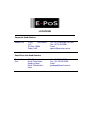
1
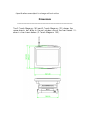
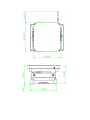
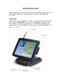
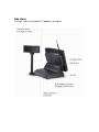
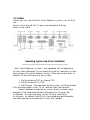
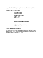
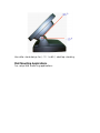
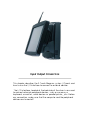
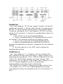
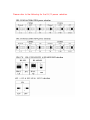
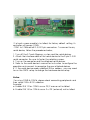
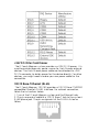
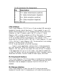
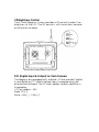
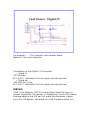
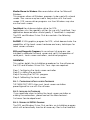
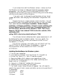
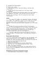
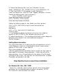
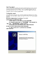
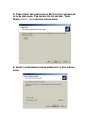
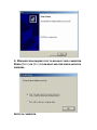
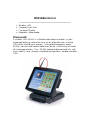
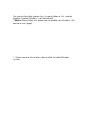
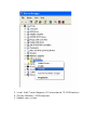
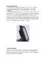
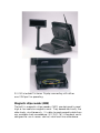
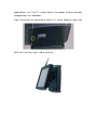
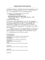
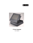
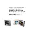
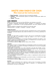
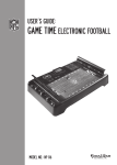
E -T ou ch Magnum
12” / 15”
Us er Manual
Company Pr of ile
E-PoS is a pioneer in the field of Retail T echnology Products operating in Middle East & South East
Asian markets. T he success story of E-PoS started five years ago when the core focus was to meet
burgeoning market share of the mid level segment. Since then E-PoS has built a substantial
market share in Retail T echnology Products with an average growth of 10-15% per year.
E-PoS not only offers total hardware solution for the Retail business but also for Banks,
Government Organizations, Filling Stations, Hospitality I ndustry, Recreation, Hospitals etc
E-PoS has a long list of satisfied customers over the Middle East, Africa & I ndian Subcontinent. A
dedicated channel of Resellers, Dealers and System I ntegrators back up the efficient & timely
distribution and After sales service
Obj ect ive
T he objective is to create reliable, viable & affordable retail hardware solution provider and to
have maximum satisfied customer base in the Middle East and there onwards to neighboring
countries like I ndia, Africa & Russia.
Dist r ibut ion R ight s
E-PoS represents some of the leading brands as their authorized distributor for Middle East &
South East Asia viz.:
Point of Sale
Star Micronics. U.K – for their range of Retail T echnology products.
Metrologic. Germany- for Barcode scanners & Data collectors.
Godex, T aiwan – for Barcode Printers.
Cash bases U.K – for Cash Drawers.
Denso, Germany – For Auto I D Solutions
Ring, Japan – For I ndustrial Barcode Printers
Banking & Security
Evolis, France – For I D Card Printing solutions
Magtek, USA – For Banking products
&
A huge range of E-PoS OEM products for POS, Banking & Security Products
Pr oduct R ange
Point of S ale Pr oduct s
•
•
•
•
•
•
•
•
•
•
•
•
Point of Sale PCs & Web terminals
T ouch Screen Systems
Printers-Line, Dot matrix, Label, Card and Point of Sale
Displays-Customer, CRT , Flat Panels, T ouch Screen
Bar Code Scanners
Bar Code Printers
Cash drawers
Magnetic and Bar Code Swipe Readers
Programmable and Miniature Keyboards
Kiosk T erminals
Portable Data T erminals
Radio Frequency terminals
B anking and S ecur it y Pr oduct s
•
•
•
•
•
•
•
•
•
Visual Card Systems
I D Card printing solutions
MI CR Check Readers & Encoders
Check book, Passbook & Passport Printers
Counterfeit detection units
Note bundling and binding machines
Cheque printers
Magnetic and Bar Code Swipe Readers
Smart Card Readers
T ar get Mar ket
•
•
•
•
•
•
Hospitality I ndustry
Banks
Government Organizations
Shopping Malls
Filling Stations
Retail Business
T ar get Cust omer s
•
•
•
•
•
•
Dealers
Resellers
Corporate Customers
Overseas/Export Customers
System I ntegrators
Value Added Resellers
Cust omer Net wor k & Mar ket ing
E-PoS has existing network of dealers in the Middle East, East Africa and I ndia. T he Y2003-04
Expansion plans include Africa and Russian continent being the emerging markets for Retail
T echnology Products.
Being the only dedicated Regional distribution company for Retail technology Products, E-PoS
have always been very aggressive in terms of marketing and promotions.
Advertisements are inserted in the local press, trade journals every month. Product brochures,
leaflets & promotion schemes are distributed through mail, Fax & Electronic mail thus offering
continuous updation about EPoS product range to its business partners. E-PoS participation in
I nternational trade exhibitions & Promotions offers more insight to the dealers and corporate end
users about Retail technology
TABLE OF CONTENTS
Introduction
-
2
Table of Contents
-
3
Location
-
4
Do’s & Don’ts
-
5
Accessories
-
6
General Information
-
7
Specifications
-
8
Dimensions
-
11
Identifying The System
-
13
Operating System & Driver Installation
-
15
Versatile Stand & Mounting
-
16
Input / Output Connection
-
17
Jumper Settings
-
19
Touch Screen
-
25
Peripheral Devices
-
33
Program Watch Dog Timer
-
39
LOCATIONS
Corporate Head Quarters
Middle East
E-PoS
International
LLC
P.O.Box 12608
Dubai, UAE
Tel: +9714-3523288 / 3512861
Fax: +9714-3513396
Email:
[email protected]
South East Asia Head Quarters
South East
Asia
E-PoS International
Nasik-Pune Road
Ayodhya Nagri
Nasik, Maharasthra
India
Tel: +91-253-2411806
Fax: +91-252-2415295
Email:
[email protected]
DO’S & DON’TS
(Integrated circuits on All E-PoS System boards are sensitive to static electricity.
To avoid damaging any Components on the computer board, before getting
started, read these following precautions and other instructions and save them for
later reference).
i.
ii.
iii.
iv.
v.
vi.
vii.
viii.
ix.
x.
xi.
xii.
xiii.
xiv.
xv.
Do not remove the computer from the anti-static Packaging until you are ready for
installation.
Make sure the voltage of the power source is correct before connecting the
computer to the power outlet, (110~220 volts).
Connect Rubber Legs provided to avoid damaging Cabinet Cover and Door,
(where provided).
Do not change any Hardware Devices online when System or the device is on and
running, because the sudden surge of power may ruin any sensitive components.
Also make sure the computer is properly grounded.
Turn off the computer before cleaning. Always clean with a damp or dry cloth
only. Do not spray any liquid cleaner on screen directly.
The power outlet socket used to plug in the computer power cord must be located
near the system and easily accessible. Do not use outlets on the same circuit of the
system that regularly switch on and off.
If the computer is sharing an extension cord with other devices, make sure the
total ampere rating of the devices plugged into the extension cord does not exceed
the cord’s ampere rating.
Do not expose the power cord, extension cord and power outlet to moisture.
The openings on the computer enclosure are for the cabin ventilation to prevent
the computer from overheating. DO NOT COVER THE OPENINGS.
Do not connect any devices to Powered COM Ports (5V/12V), other then the
devices that take power from Powered COM Ports to avoid damaging the Device.
Any Hardware upgrades or changes to be made are to be informed, and do not
tamper with Serial Nos. and Warranty Seals, to avoid Warranty Void.
If the computer is not equipped with an operating system. An operating system
must be loaded first before installing any software into the computer.
If the computer is equipped with a touch panel, avoid using sharp objects to
operate the touch panel. Scratches on the touch panel may cause mal-calibration
or non-function to the panel.
The LCD panel display is not subject to shock or vibration. When assembling the
computer, make sure it is securely installed.
Choose an Ideal dust free location and reliable surface for the System with proper
ventilations.
ACCESSORIES
1. Warranty Card.
2. Power Cable.
3. Driver Bank CD.
4. External IDE Connection Cable.
5. Wireless Antenna. (Optional)
6. Modem Cable. 2 Nos. (Optional)
General Information
__________________________________________________
T he E-Touch Magnum is a s er ies of 12.1”/15” multimedia I ntel
Celer on or Pentium ® I I I panel PCs des igned to s er ve as a fr iendly
POS - machine for eas y integr ation into any s pace- cons tr icted r etail
and infor mation applications .
I n ter ms of panel s iz e, the E- T ouch Magnum has 12.1” and
15”
Models .
Onboar d featur es include s uper I /Os , XGA, 12.1”/15” T FT flat
Panel, touch s cr een, Ether net and multimedia functions . T he full PC
functionality coupled with its multi- I /Os s tand r eady to
accommodate a wide r ange of PC per ipher als . S pecial indus tr ial
featur es not commonly s een in commer cial s ys tems s uch as
watchdog timer and water /dus t pr oof fr ont panel make it a bes t
choice for the oper ation in any hos tile envir onments .
Fully configur able and with its s leek outlook, the E-Touch
Magnum is
an ideal platfor m for any r etail and infor mation applications .
Specifications
__________________________________________________
T his handbook contains mos t infor mation you need to s et up and
us e the E- T ouch Magnum s ys tem. You do not need to r ead
ever ything in this handbook to us e the s ys tem.
SYSTEM
Flat Panel
ϖ E-Touch Magnum 120:
Viewing angle
100
Luminance (cd/m 2 )
150 nits
S imultaneous mode yes
12.1” color T FT , 800* 600
ϖ E-Touch Magnum 150:
15” color T FT , 1024* 768
Viewing angle
100
Luminance (cd/m 2 )
250 or above
S imultaneous mode yes
ϖ CP U (Socket 370)
I ntel T ualatin FCPGA2 up to 1.5GHz
I ntel Pentium I I I FCPGA 100/133 up to 1GHz
Celer on FCPGA 66/100 up to 1.5GHz
ϖ System BIOS
Awar d PnP Flas h B I OS
ϖ System Memory
2* 168pin DI MM s ocket s uppor ting S DRAM up to 1 GB
ϖ L2 Cache
CPU built- in
ϖ Standard I/O
4 x S er ial Por ts (COM1, COM 4, COM 5, COM6) with + 5V/12V
power output on pin 9: 3 x RS - 232, 1 x RS - 232/422/485 (COM4), 1
x r es er ved for I r DA(COM 2) & 1 x r es er ved for T ouch s cr een(COM3)
1
3
1
1
2
1
1
1
1
1
1
x
x
x
x
x
x
x
x
x
x
x
Par allel Por t s uppor ts S PP/EPP/ECP
US B por ts
VGA por t
RJ- 45 LAN por t
RJ- 11 modem phone j ack
PS /2 K eyboar d connector
PS /2 Mous e connector
RJ- 12 6 pin cas h dr awer connector
Ex ter nal I DE por t
DC Jack for 24VDC input Cas h Dr awer
Compact Flas h S lot
ϖ Ethernet
100/10 B as e- T Ether net with RJ- 45 phone j ack
Wir eles s 100/10 B as e- T Ether net (option)
ϖ Watchdog Timer
64 level time inter vals
ϖ Display
I ntegr ating VGA/LCD/Contr oller , advance har dwar e
2D/3D GUI engine
S har e S ys tem Memor y Ar chitectur e, which can flex ibly
utiliz e the fr ame buffer s iz e up to 64MB
ϖ
1 x
1 x
1 x
3 x
Front Bezel
I r DA Data tr ans mis s ion S I R
Power On/Off S witch
Floppy Dis k Dr ive B ay
LED for HDD, LAN, Power
PERIPHERAL & STORAGE DEVICES
ϖ Touch screen (optional, s har ing COM3)
12.1”/15” analog r es is tive type with RS - 232 Contr oller
ϖ Optional devices
Wir eles s LAN 802.11b with Antenna
VFD, 20 columns x 2 lines
LCD, 30 columns x 4 lines
I nter nal 56K Modem Module
Compact Flas h
MS R 2 tr acks or 3 tr acks
US B por t for US B I D key for s ecur ity contr ol
ϖ Power Supply
AC 150W, input r ange: 100~ 230VAC @ 47~ 63Hz
ϖ Speakers
S peaker s * 2
MECHANICAL & ENVIRONMENTAL
ϖ Construction
I ns ide: heavy- duty s teel
Outs ide: fir e- pr oof r es ilient plas tic
ϖ Color (s tandar d)
B lack: Pantone 3x 2X
ϖ Dimension
E- T ouch Magnum 120 / 150: 368* 321.7* 107.5 mm ( T his does not
I nclude the dimens ion of the s tand.)
ϖ Mounting
Wall mount with mounting kits
ϖ Versatile Stand
S T AND: - 10~ 85’
*Specifications are subject to change without notice.
Dimensions
__________________________________________________
T he E- T ouch Magnum 150 and E- T ouch Magnum 120 s har es the
s ame chas s is but differ in the cut window s iz e of the fr ont bez el. I t’s
chas s is s iz e s hown below (E- T ouch Magnum 150).
Identifying the System
________________________________________________________________________
B efor e getting s tar ted, take a moment to familiar iz e your s elf with
the s ys tem and the I /O ar r angement of the E- T ouch Magnum
120/150.
Front View
When the E- T ouch Magnum 120/150 is put upr ight on the des ktop
with the pr ovided pedes tal, its fr ont view appear s as below. T he
illus tr ations of the E- T ouch Magnum 120/150 may differ s lightly
becaus e the E- T ouch Magnum s ys tem s er ies has two differ ent LCD
s iz e: 12.1” & 15”.
Side Views
T he left s ide of the panel PC appear s as below:
I/O Outlets
When you tur n ar ound the E- T ouch Magnum s ys tem, you will find
the
power s witch and all the I /O por ts ar e located at the r ear
cover of the s tand.
Operating System and Driver Installation
_____________________________________________
T he E- T ouch Magnum s ys tem is not equipped with an oper ating
S ys tem when deliver ed. S o you need to ins tall an Oper ating S ys tem
and configur e the dr iver befor e s tar ting. T her e ar e s ever al ways to
load an OS and s oftwar e into the s ys tem.
1. Via the ex ter nal FDD or inter nal FDD
2. Via the ex ter nal CD- ROM
3. Via Ether net: You can boot up the s ys tem via Ether net boot
ROM and download s ys tem OS or s oftwar e fr om the networ k.
Recent r eleas es of oper ating s ys tems always include s etup
pr ogr ams that load automatically and guide you thr ough the
ins tallation. You can als o r efer to your OS us er manual for
ins tr uctions , by default Har d Dis k is for matted and par titioned by
the Manufactur er and neces s ar y S ys tem files loaded.
T he E- T ouch Magnum s ys tem pr ovides the following utility
dr iver s
S tor ed in the CD- ROM dis kette;
E t h er n et u t i l i t i es
W i r el es s u t i l i t i es
VGA u t i l i t i es
T ou ch s cr een dr i ver s
U S B I D K ey
MMR / VF D
VERSATILE STAND & MOUNTING
___________________________________________
:
:
Angle fr ee Des ktop s tanding
Wall Mounting
-10 to 85o Desktop Standing
T he s leek and s table pedes tal as s embled with the bas e enables the
E- T ouch Magnum s ys tem to endur e the long- time oper ation in any
public s ector s . T he 2 s ide hinges pulling the bas e up and down, the
angle can be adj us ted fr om - 10 to 85 0 .
Ver s atile s tand des ign for (- 10 ° to 85 °) des ktop s tanding
Wall Mounting Applications
For s etup Wall mounting applications .
Input Output CONNECTION
_____________________________________________________
T his chapter des cr ibes the E- T ouch Magnum s ys tem I /O por ts and
how to us e the I /O inter face to connect to ex ter nal devices .
T he I /O inter faces located at the backs ide of the chas s is ar e us ed
to connect ex ter nal per ipher al devices , s uch as a mous e, a
keyboar d, a monitor , s er ial devices or par allel pr inter …etc. B efor e
any connection, make s ur e that the computer and the per ipher al
devices ar e tur ned off.
Parallel Port
T he E- T ouch Magnum 120/150 can s uppor t the lates t E PP and ECP
par allel por t pr otocols . I t can be us ed to connect to a wide ar r ay of
pr inter s , Z I P dr ive, par allel s canner and any other par allel devices .
T he pr inter inter face on the E- T ouch Magnum 120/150 is a 25- pin
female D- S UB connector . T o connect any par allel device, follow the
s teps below:
1. T ur n off the s ys tem and the par allel devices .
2. Plug in the male connector of the par allel device to the 25pin female D- S UB connector and fas ten the r etaining s cr ews .
3. T ur n on the s ys tem and the attached par allel devices .
4. Refer to the par allel device’s manual for ins tr uction to
configur e the oper ation envir onment to r ecogniz e the new attached
devices .
5. You may need to r un the CMOS s etup to change the
har dwar e device s etup.
COM Ports x 4
T he E- T ouch Magnum 12 / 15 featur es with four onboar d COM
por ts located at the r ear s ide of the chas s is , r eady to connect to a
wide r ange of s er ial devices . COM1, COM5 & COM6 ar e RS - 232 and
COM4 is RS - 232/422/485, s elected via j umper s etting. COM 2
r es er ved for I r DA & COM3 for T ouch s cr een. Each COM por t is with
+ 5V/+ 12V power capabilities on pin 9, pr oviding eas y
accommodation to a br oad r ange of s er ial devices .
T he COM por t 5V/12 power is s elected via j umper s etting on the
I O–T R boar d. T he I O- T R is the I O boar d docked to the s ys tem
mother boar d to connect the onboar d s ignal out to the ex ter nal I /O
por ts .
Pleas e r efer to the following for the 5V/12 power s election.
I f a touch s cr een module is ins talled, for factor y default s etting, its
contr oller will occupy COM3.
COM1 to COM6 ar e all D- S UB 9- pin connector s . T o connect to any
s er ial device; follow the pr ocedur es below;
1. T ur n off the E- T ouch Magnum s ys tem and the s er ial devices .
2. Attach the inter face cable of the s er ial device to the 9- pin D- S UB
s er ial connector . B e s ur e to fas ten the r etaining s cr ews .
3. T ur n on the computer and the attached s er ial devices .
4. Refer to the s er ial device’s manual for ins tr uction to configur e the
oper ation envir onment to r ecogniz e the new attached devices .
5. I f the s er ial device needs s pecified I RQ or addr es s , you may need
to r un the CMOS s etup to change the har dwar e device s etup.
Notice:
For us ing COM5 & COM 6, pleas e check connecting per ipher als and
then s etup I RQ in B I OS s election.
Ex ample:
a. Enable I RQ 12 for COM 5 us e as PS /2 mous e not ins talled.
b. Enable I RQ 15 for COM 6 us e as 2 nd I DE (ex ter nal) not ins talled.
+24V DC-IN for Cash Drawer
T he E- T ouch Magnum s ys tem pr ovides a + 24V DC- I N power . I t is
us ed to pr ovide neces s ar y power s our ce for Cas h Dr awer ex ter nal
devices . T he Cas h Dr awer power cable can be attached to + 24V
DC- I N connector to obtain power for the device dir ectly. For other
devices , you might need to make your own power cable for the
connection.
100/10 Base-T Ethernet (RJ-45)
T he E- T ouch Magnum 120/150 pr ovides a 100/10 B as e- T NE2000
compatible Ether net (RJ- 45) inter face. For networ k connection,
follow the ins tr uctions below.
1. T ur n of the E- T ouch Magnum s ys tem and the Ether net hubs .
2. Plug in one end of cable of a 100/10 B as e- T hub to the s ys tem’s
RJ- 45 phone j ack. T he pin as s ignment of the RJ- 45 is lis ted as
follow;
VGA Interface
T he E- T ouch Magnum 120/150 has a 15- pin analog RGB connector
located at the r ear s ide of the chas s is . I t can s uppor t its own LCD
dis play and an ex pans ion CRT or analog monitor at the s ame time.
However , as the LCD panel us ed in the 15” s ys tem (E - T ouch
Magnum 150) is of the r es olution of 1024 x 768 and in 12.1”
s ys tem (E- T ouch Magnum 120) is 800 x 600, ther efor e, to s uppor t
a CRT or analog monitor s imultaneous ly, the monitor ’s VGA
r es olution has to be s et to 800 x 600 for E- T ouch Magnum 120 and
1024 x 768 for E- T ouch Magnum 150. T he connection to an analog
monitor is an eas y plug- in of the VGA
D- S UB 15- pin connector to the RGB inter face.
T her e is s ome application s oftwar e that is to be ex ecuted in
800* 600 r es olution. When the s oftwar e is r unning under E- T ouch
Magnum 150, only par t of the s cr een will s how on the LCD dis play.
I f the application has to r un in full s cr een, you need to update the
s ys tem VGA dr iver s with an auto ex pans ion utility. However , due to
r es olution limitation, the tex t mode will look s lightly dis tor ted.
PS/2 Keyboard Interface
T he E- T ouch Magnum 120/150 pr ovides a s tandar d PS /2 keyboar d
connector located at the r ear panel. I f the us er would lik e to us e AT
keyboar d, then an adapter to connect the PS /2 K B to AT K B is
needed.
PS/2 Mouse Interface
T he E- T ouch Magnum s ys tem has one PS /2 mous e connector
located at the r ear s ide. A s imple plug- in will make the connection.
VR Brightness Control
T he E- T ouch Magnum s ys tem pr ovides a VR contr ol to adj us t the
br ightnes s of the LCD. T he VR contr ol is with two buttons and one
on/off button as below.
DIO (Digital Input & Output) for Cash Drawers
T he Magnum als o equipped with a digital I /O that pr ovide 2 digital
in and digital out T T L level inter face, eas y to pr ogr amming the
ex ter nal contr ol boar d. T he DI O por t addr es s and pin definition is
lis ted below;
I /O Por t addr es s : 440
Read: DI N_ 0
Wr ite: CAS H_ 1, CAS H_ 2
For ex ample - - - - - POS machine’s cas h- dr awer Game
Machine’s Coin ins er t detection
.
.
.
T he following is the Digital I /O ins tr uction:
• Digital in:
I OR 440(Hex )
B it 0 & B it 1 valid data (T he two s ignals nor mally pull low)
• Digital out:
I OW 440(Hex ), Data
B it 0 & B it 1 valid data (T he two s ignals nor mally pull low)
USB Ports
T he E- T ouch Magnum 120/150 als o pr ovides thr ee US B por ts to
connect to ex ter nal US B devices . A s imple plug- in of the US B device
inter face cable to the US B por t will make the connection. B efor e
us ing the US B devices , r emember to ins tall the device dr iver fir s t.
TOUCH SCREEN
_____________________________________________________________________________
For keyboar d les s oper ation, the E- T ouch Magnum 120/150
pr ovides an optional touch s cr een. T he E- T ouch Magnum s ys tem
can us e either ELO r es is tive type touch s cr een or 5 wir es r es is tive
touch s cr een. T his chapter details the pr ocedur es to ins tall the
s oftwar e dr iver s under DOS and Windows oper ation.
Elo Touch screen Driver Installation
___________________________________________________
T he Elo r es is tive touch and I ntelli touch will us e the s ame dr iver s
and utilities , which ar e s tor ed in the Dr iver CD dis kette.
System Requirements
T he DOS dr iver s will r un on any s ys tem with DOS 2.0 or later
ver s ion. T he Windows dr iver s will r un on any s ys tem with Windows
3.1 or later ver s ions . T he DOS demons tr ation pr ogr am r equir es a
VGA color dis play. T he touch s cr een calibr ation pr ogr am for DOS
s uppor ts s tandar d and VES A- compatible dis play modes . Other wis e,
all s oftwar e is video independent. An Elo touch s cr een mus t be
ins talled on the dis play and connected to a s er ial or bus contr oller .
About Elo Software
Software Included
T he accompanying DOS and Windows Dr iver Dis k contains the
following Elo dr iver s oftwar e:
Elo DEV T ouch s cr een dr iver pr ogr am for DOS :
T his pr ogr am makes all Elo touch s cr een contr oller s , including s er ial
RS - 232, PC- B us , and Micr o Channel ver s ions look the s ame to other
dr iver and application pr ogr ams .
Monitor Mouse for DOS Mous e emulation dr iver for DOS :
T his pr ogr am combines touch input fr om EloDEV and mous e input
fr om your mous e dr iver into a s ingle MOUS E.COM- compatible
application inter face.
Monitor Mouse for Windows Mous e emulation dr iver for Micr os oft
Windows :
T his pr ogr am allows all Windows pr ogr ams to be us ed with a touch
s cr een. Your mous e may be us ed in conj unction with the touch
s cr een. DOS mous e- dr iven pr ogr ams r un fr om Windows may als o
us e the touch s cr een.
TouchBack K eys tr oke emulation dr iver for DOS ;
Applications mus t be s pecially wr itten for us e with T ouchB ack. Your
application documentation s hould s pecify if T ouchB ack is r equir ed.
T he DOS and Windows Dr iver Dis k als o contains the following
s oftwar e:
EloDEMO A VGA- gr aphics pr ogr am for DOS , which demons tr ates the
capabilities of the touch s cr een har dwar e and many techniques for
touch s cr een s oftwar e.
Utility and Diagnostic Programs An as s or tment of pr ogr ams ar e
included to calibr ate the touch s cr een and ver ify the oper ation of
s er ial por ts , touch s cr een contr oller s , and dr iver pr ogr ams .
Installation
T his s ection details the ins tallation pr ocedur es for the s oftwar e on
the DOS and Windows Dr iver Dis k. Four s teps ar e r equir ed:
S tep 1
S tep 2
S tep 3
S tep 4
Configur ing the touch s cr een contr oller
I ns talling the contr oller
Running the I NS T ALL pr ogr am
Calibr ating the touch s cr een
STEP 1 - CONFIGURING THE TOUCH SCREEN CONTROLLER
T HE MANUFACT URER s hips mos t touch s cr een contr oller s
pr econfigur ed for us e with Elo s oftwar e.
STEP 2 - INSTALLING THE CONTROLLER
I f you need help when ins talling the touch s cr een contr oller or
making the connections , pleas e contact the Manufactur er ’s
Cus tomer S er vice depar tment.
STEP 3 - RUNNING THE INSTALL PROGRAM
T he DOS and Windows Dr iver Dis k contains an ins tallation pr ogr am
which will automatically tr ans fer all neces s ar y files to the har d dis k.
I f you intend to ins tall the Windows dr iver s , make s ur e that
the Windows has been ins talled and oper ating pr oper ly befor e
pr oceeding. You must have a DOS mouse driver (MOUSE.COM)
installed for your mouse if you wish to continue using your mouse along
with the touch screen in DOS or Windows.
I f you only want to change the configur ation of your touch
s cr een contr oller , see changing Your Hardware Configuration with
SETUP.
Res pond to the on- s cr een pr ompts and ins tr uctions . You will
be as ked to s pecify the model and configur ation of your contr oller ,
then s elect between DOS Express Installation, Windows Express
Installation, or Selective Installation. The touch screen controller of the
E-Touch Magnum 120/150 I is serial type. The model number is E2712210 AccuTouch. Baud rate of the controller is “9600”. The E -Touch
Magnum 120/150 I uses onboard COM3 to drive this controller, IRQ is
selected by BIOS
setting. IRQ10 is the factory default setting for COM3.
T he s oftwar e to be ins talled and dis k s pace r equir ements will
be dis played for each ins tallation option. You may s pecify the
dr ive and dir ector y for the files you choos e to ins tall, or us e
the default (C: \T OUCH).
T he I NS T ALL pr ogr am will modify your AUT OEXEC.B AT file,
(and S YS T EM.I NI file for Windows ins tallations ). Copies of
the or iginal files will be s aved as AUT OEXEC.OLD and
S YS T EM.OLD.
Installing MonitorMouse for Windows system
1. T ur n on your computer .
2. T o ins tall the s oftwar e, ins er t the Dr iver CD. T he path as
x : \Dr iver s \E lo T ouch\ (X = your CD device number )
3. Open one folder which s ame as your oper ating s ys tem.
4. Double click the only one file in this folder and Unz ip to a
folder s uch as “c: \EloWin9X”.
5. Chang to “c: \EloWin9X” double click s etup.ex e.
6. Following the ins tr uctions on the s cr een.
7. T he T ouch s cr een S etup Wiz ar d will appear . You will need to
s pecify the type of touch s cr een contr oller you ar e us ing and how it
is connected.
Contr ol type:
s er ial
S mar tS et:
2x x 0
COM por t:
COM3
8. Complete the S etup pr ogr am.
9. Res tar t your s ys tem.
10. Click the S tar t button, then click S ettings , and then click
Control Panel.
11. Double- click Elo Touch screen to r un the T ouch s cr een
Contr ol panel.
12. Click the Calibrate button and touch each of the thr ee tar gets as
they appear on the s cr een. Click Yes when the cur s or lines up
cor r ectly with your finger . Click OK to clos e the T ouch s cr een
Contr ol panel.
NOTES
Full- s cr een DOS mode is not s uppor ted. However , Windowed
DOS mode is fully s uppor ted. A touch to a full- s cr een DOS s es s ion
will caus e your s ys tem to immediately r etur n to your Windows
des ktop. A mous e can be us ed to acces s pr ogr ams r un in full- s cr een
DOS
mode.
Windows 95 may lock up dur ing s tar tup if the r es our ce
s ettings in the S etup dialog of the Touch screen Control Panel do not
match the actual contr oller configur ation. Us e Safe Mode to s tar t
Windows 95 and change the r es our ce s ettings to match the
contr oller configur ation, then r es tar t Windows 95.
T he touch s cr een dr iver may caus e Windows 95 to lock up
dur ing S hutdown if the touch s cr een is activated after S hutdown is
initiated.
Removing the Mouse Pointer
I f you wis h to eliminate the mous e pointer , you may r eplace it with
the null cur s or file, NULL.CUR, s upplied with Monitor Mous e for
Windows 95. Follow the following s teps to ins tall the null cur s or file;
1. Open the Control Panel and s elect Mouse.
2. S elect the Pointers tab.
3. Highlight the Normal Select cur s or then s elect Browse.
4. T ype “ null.cur ” in the s pace pr ovided and s elect Open.
5. S elect OK to s elect the option.
6. Ex it fr om the Mouse Control Panel. You s hould notice that the
ar r ow cur s or has dis appear ed. Note that all other cur s or s will s till
function as befor e.
MonitorMouse for Windows 95 Uninstall Procedure
1. Clos e the Windows Control Panel if it is open.
2. Delete the following files fr om your \Windows \S ys tem
folder : MONMOUS E .VXD, MONMOUS E.HLP, and MONMOUS E.CPL.
3. S tar t the REGEDI T .EXE pr ogr am to edit the r egis tr y
(click the Start button, click Run, type " r egedit" and pr es s < Enter > ).
Delete the following keys fr om the r egis tr y:
HK EY_ CURRENT _ US ER\Contr ol
Panel\des ktop\DoubleClickHeight
HK EY_ CURRENT _ US ER\Contr ol
Panel\des ktop\DoubleClickWidth
Delete the following r egis tr y key folder s and their contents :
HK EY_ LOCAL_ MACHI NE\S ys tem\Cur r entContr olS et\S er
vices \Vx D\
MonMous e
HK EY_ LOCAL_ MACHI NE\S OFT WARE\E lo
T ouchS ys tems
4. Us e Notepad to delete the following line fr om the [ 386Enh]
s ection of the S YS T EM.I NI file: device= monmous e.vx d
5. Delete the dir ector y C: \Elo to r emove the touch s cr een diagnos tic
pr ogr ams and s ample Z - ax is and calibr ation pr ogr ams .
Res tar t Windows .
Getting More Information
For mor e infor mation on ins talling the Elo s oftwar e dr iver to the ET ouch Magnum s ys tem or to download Elo touch s cr een dr iver s ,
pleas e vis it Elo T ouch s ys tem webs ite
http: //www.elotouch.com
Click the Support button and follow the ins tr uction on the s cr een to
download Elo s oftwar e or documentation. I f after cons ulting the
documentation, you s till need help with the s etup of the Elo touch
s oftwar e to the s ys tem, you can click the Technical button to locate
Elo global s er vice points for help.
Wires Resistive Touch screen Driver Installation
________________________________________________________________________
For Windows 98 / Me / NT4 / 2000
T ouch K it is s oftwar e, which contains dr iver s of the touch panel
contr oller s for the s pecified communication connector s , RS 232,
PS /2 and US B , and the other two utilities :
Touch Tray support
T his is utility for s imulating the r ight and left button of your mous e
thr ough contr olling touch panel. You can toggle between r ight or
left mous e buttons by this utility. Als o, you can toggle the mous e
mode for click or dr awing application.
Configuration support
T he calibr ation and dr aw tes t of touch panel ar e done by this utility.
B es ides , you can add or s ear ch for new RS - 232 or PS /2 touch panel
devices .
FOLLOW THESE STEPS TO INSTALL TOUCHKIT.
(AN EXAMPLE FOR WINDOWS 98.)
1. PUT THE TOUCHKIT CD TO YOUR CD-ROM.
2. CHANGE DIRECTORY TO “WIN98ME.” (OR CHANGE TO
“NT_4.0”, “WINXP2000” RESPECTIVELY)
3. DOUBLE CLICK THE SETUP.EXE, THEN WINDOWS
STARTS TO RUN THE INSTALLATION PROGRAM.
4. JUST CLICK [NEXT>] BUTTON TO CONTINUE
INSTALLATION.
5. THEN CHECK THE CHECK BOX IF PS/2 TOUCH CONTROLLER
IS TO BE INSTALLED. THE DEFAULT IS UNCHECKED. THEN
PRESS [ NEXT >] TO CONTINUE INSTALLATION.
6. SELECT APPROPRIATE FOLDER WHERE SET UP WILL INSTALL
FILES.
PRESS ON THE [NEXT>]
BUTTON TO CONTINUE.
7. THEN TYPE IN YOUR PROGRAM FOLDER’S NAME FOR
TOUCHKIT OR PRESS ON [NEXT>] TO CONTINUE. THERE WILL BE
A DEFAULT NAME FOR IT.
8. WINDOWS IS COPYING FILES TO DISK AND THE SETUP IS
COMPLETE. CLICK [FINISH>] TO TERMINATE.
9. WINDOWS WILL REQUEST YOU TO RE-BOOT YOUR COMPUTER.
PRESS [YES>] OR [NO>] TO RE-BOOT AND THE INSTALLATION IS
FINISHED.
SETUP IS COMPLETE.
PERIPHERAL DEVICES
____________________________________________________
ϖ
ϖ
ϖ
ϖ
Wir eles s LAN
Compact Flas h S lot
Cus tomer Dis play
Magnetic s tr ipe r eader
Wireless LAN
A wir eles s LAN (WL AN) is a flex ible data communication s ys tem
implemented as an ex tens ion to or as an alter native for , a wir ed
LAN within a building or campus . Us ing electr omagnetic waves ,
WLANs tr ans mit and r eceive data over the air , minimiz ing the need
for wir ed connections . T hus , WLANs combine data connectivity with
us er mobility, and, thr ough s implified configur ation, enable movable
LANs .
For mor e infor mation pleas e tur n to s ame folder as this manual
location. Named “Wir eles s Us er Manual.pdf”
**Notice: Pleas e follow our pr oces s ion to enable your Wir eles s LAN
device as nex t page.
1. Pleas e r emove the wir eles s device after ins talled Windows
s ys tem.
2. I ns er t the E- T ouch Magnum CD into ex ter nal CD- ROM and r un
X: \Dr iver s \Wir eles s LAN\S etup.ex e.
3. Reboot your s ys tem
Compact Flash Slot
E- T ouch Magnum S uppor ting Compact Flas h T ype I /I I . Compact
Flas h car ds ar e des igned with flas h technology, a nonvolatile
s tor age s olution that does not r equir e a batter y to r etain data
indefinitely.
T he only differ ence between CF T ype I and CF T ype I I car ds is the
car d thicknes s . CF T ype I is 3.3 mm thick and CF T ype I I car ds ar e
5mm thick. A CF T ype I car d will oper ate in a CF T ype I or CF T ype
I I s lot. A CF T ype I I car d will only fit in a CF T ype I I s lot. T he
electr ical inter faces ar e identical. Compact Flas h is available in both
CF T ype I and CF T ype I I car ds , though pr edominantly in CF T ype I
car ds . T he Micr odr ive is a CF T ype I I car d. Mos t CF I /O car ds ar e CF
T ype I , but ther e ar e s ome CF T ype I I I /O car ds .
Customer Display
T he Cus tomer Dis play is an ar tis tic des ign POS s ys tem per ipher al
device. I t is for us e with POS s ys tem to dis play the pur chas ed
pr ices and the amount of change to cus tomer s . Als o it is capable to
dis play the adver tis ing Mes s age.
RS - 232 inter face Cus tomer Dis play connecting with either
one COM por t for oper ating.
Magnetic stripe reader (MSR)
The built- in magnetic s tr ipe r eader s (MS R) ar e des igned to r ead
high or low coer cive magnetic car ds . T hey decode and ver ify the
data tr acks s imultaneous ly. I t is able to r ead magnetic data fr om
any available tr ack encoded per I S O 7810- 7813 s tandar ds and is
des igned for us e in acces s contr ol, r etail and time attendance
applications , etc. T he T T L output allows the r eader to be univer s ally
accepted by mos t decoder s .
Pr es s the button as r ed cir cle as blew in E- T ouch Magnum r ear s ide.
MS R will r is e fr om r ight s ide as pictur e.
Programming the Watchdog Timer
_____________________________________________________________________________
T he Magnum featur es a watchdog timer that can gener ate a s ys tem
r es et if the CPU pr oces s ing comes to a halt. T his featur e ens ur es
the s ys tem dependability dur ing unattended oper ation.
T he following is the Watchdog T imer ins tr uction:
• IOW 444(Hex),Timer(Hex) --------Enable/Setting/refresh Watchdog Timer
Timer: 64 levels setting (1 ~ 64 seconds, tolerance +-20%)
• IOR 441(Hex) -------------------------Disable Watchdog Timer
I f you want to us e the watchdog timer , you mus t wr ite a pr ogr am
which wr ites I /O por t addr es s 444(Hex ) at timer s etting inter vals . T he
fir s t time your pr ogr am wr ites the por t, it s ets and enables the
watchdog timer . Pr ogr am mus t wr ite the por t at time inter vals .
Other wis e the watchdog timer will activate and r es et the CPU. When
you want to dis able the watchdog timer , your pr ogr am s hould r ead I /O
por t 441(Hex ).
I f CPU pr oces s ing come to a s tands till becaus e of a s oftwar e bug
or EMI , pr ogr am’s s ignals to I /O por t addr es s 444(Hex ) to the timer
will be inter r upted. T he watchdog timer will automatically r es et the
CPU, and data pr oces s ing will continue nor mally.
Ex ample pr ogr am
5 REM Watchdog timer
10 X=OUTP(&H444)Timer REM Enable / Setting the Watchdog timer
15 GOSUB 500
20 X=OUTP(&H444)Timer REM Refresh the Watchdog timer
25 GOSUB 600
30 X=OUTP(&H444)Timer REM Refresh the Watchdog timer
35 GOSUB 800
X=INP(&H441) REM Disable Watchdog timer
45 END
500 REM Subroutine takes shorter than setting level to complete
.
.
550 RETURN
600 REM Subroutine takes shorter than setting level to complete
.
.
680 RETURN
800 REM Subroutine takes shorter than setting level to complete
.
.
870 RETURN
________________________________________________________________________
E-Pos InternationalL.L.C,P.O .Box N o.12608,D ubai,U .A .E,
Tel.N o.(+9714) 3523288,Fax.N o.(+9714) 3513396,
E-M ail:eposintl@ em irates.net.ae