1
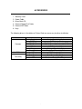
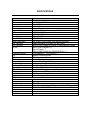
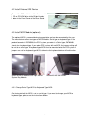
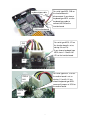
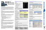
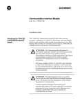
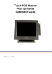
E-Touch Integrated Us er Manual TABLE OF CONTENTS Introduction - 2 Table of Contents - 3 Location - 4 Do’s & Don’ts - 5 Accessories - 6 Input /Output Function - 7 Specifications - 8 Peripherals Installation - 9 Driver Installation - 18 Jumper Settings - 25 • LOCATIONS Corporate Head Quarters Middle East E-PoS International LLC P.O.Box 12608 Dubai, UAE Tel: +9714-3523288 / 3512861 Fax: +9714-3513396 Email: [email protected] South East Asia Head Quarters South Asia East E-PoS International Nasik-Pune Road Ayodhya Nagri Nasik, Maharasthra India Tel: +91-253-2411806 Fax: +91-252-2415295 Email: [email protected] • DO’S & DON’TS (Integrated circuits on All E-PoS System boards are sensitive to static electricity. To avoid damaging any Components on the computer board, before getting started, read these following precautions and other instructions and save them for later reference). i. ii. iii. iv. v. vi. vii. viii. ix. x. xi. xii. Do not remove the computer from the anti-static Packaging until you are ready for installation. Make sure the voltage of the power source is correct before connecting the computer to the power outlet, (110~220 volts). Connect Rubber Legs provided to avoid damaging Cabinet Cover and Door, (where provided). Do not change any Hardware Devices online when System or the device is on and running, because the sudden surge of power may ruin any sensitive components. Also make sure the computer is properly grounded. Turn off the computer before cleaning. Always clean with a damp or dry cloth only. Do not spray any liquid cleaner on screen directly. The power outlet socket used to plug in the computer power cord must be located near the system and easily accessible. Do not use outlets on the same circuit of the system that regularly switch on and off. If the computer is sharing an extension cord with other devices, make sure the total ampere rating of the devices plugged into the extension cord does not exceed the cord’s ampere rating. Do not expose the power cord, extension cord and power outlet to moisture. The openings on the computer enclosure are for the cabin ventilation to prevent the computer from overheating. DO NOT COVER THE OPENINGS. Do not connect any devices to Powered COM Ports (5V/12V), other then the devices that take power from Powered COM Ports to avoid damaging the Device. Any Hardware upgrades or changes to be made are to be informed, and do not tamper with Serial Nos. and Warranty Seals, to avoid Warranty Void. If the computer is not equipped with an operating system. An operating system must be loaded first before installing any software into the computer. xiii. If the computer is equipped with a touch panel, avoid using sharp objects to operate the touch panel. Scratches on the touch panel may cause mal-calibration or non-function to the panel. xiv. The LCD panel display is not subject to shock or vibration. When assembling the computer, make sure it is securely installed. xv. Choose an Ideal dust free location and reliable surface for the System with proper ventilations. • ACCESSORIES 1. Warranty Card. 2. Power Cable. 3. Driver Bank CD. 4. External Floppy Disk Cable. 5. External IDE Cable. 6. Keys. The following drivers in the folders of Drivers Bank are necessary for driver installation: Folder Common B63 Test Utility Driver Acrobat BIOS Tool CD ROM Drv Elo Touch LAN drive Netmos Smart Card VGA Card Reader Cash Drawer VFD Function Acrobat Reader Installation BIOS Update Tool CDROM Driver Installation (for DOS) Touch Screen Driver Installation LAN Driver Installation Net mos Driver Installation Smart Card Driver Installation VGA Driver Installation Card Reader Test Program Cash Drawer Test Program Customer Display Test Program • INPUT / OUTPUT FUNCTIONS 2.1 Front View 2 1 2.2 Rear View 15 14 13 12 16 3 # 1 2 3 4 4 5 Function USB 1 & 2 Compact Flash Keyboard Mouse 6 # 5 6 7 8 7 Function VGA Printer COM2 COM1 # 9 10 11 12 • 8 9 Function LAN AC Power Power Fan DIO 10 11 # Function 13 COM3 14 COM4 15 External FDD 16 External CD-ROM SPECIFICATIONS Item M/B CPU Co-processor Internal Cache External Cache System RAM BIOS Core Logic Video Display Video RAM Video Display port HDD Controller FDD Controller I/O Port Keyboard & Mouse LAN USB ROM disk Compact Flash Expansion Slot on board Main board Dimension System Dimension POS400 Weight (Net) LCD panel Back light life Touch panel VFD Module Data transmission Synchronization Handshaking Signal level Baud rates Parity Bit length Stop bits Description B63 Intel PPGA / FC-PGA Processor Built-in CPU Built-in CPU Built-in CPU 2 x 168pin DIMM sockets, support 16 / 32 / 64 / 128 / 256 MB AWARD PnP BIOS Intel FW82443ZX / BX S3 Trio 3D AGP 4MB SGRAM One 15-pin D-SUB female VGA monitor connector Support two 40-pin 2.54 pitch IDE pin-header SMSC37C602 support one 34-pin 2.54mm pitch pin-header 9-pin D-SUB COM port x 4 10-pin DIO port x 1 25-pin D-SUB Parallel Port (SPP/EPP/ECP) x 1 PS2 Keyboard x 1 , PS2 mouse x 1 Optional LAN Rising Card USB x 2 Disk On Chip Socket supported Compact Flash Socket Supported Manufacturer Bus Slot for system expansion slot used 29cm(W) x 21cm(D) 36cm(W) x 33.5cm(D) x 36 cm(H) 7.5 Kgs. (16.5 Lbs.) 12.1-inches, color TFT type, 800 x 600 25,000 hours until brightness is reduced to half Resistor film type Serial Asynchronous DTR / DSR Mark = -3 to –15 V (logic “1”), Space = +3 to +15 V (logic “0”) 4800, 9600, 19200, 38400 bps None, even 8 bits 1 or more • PERIPHERALS INSTALLATION 4.1 Install External FDD Use the floppy cable from the accessory bag to connect the floppy disk drive to the system bay module. 4.1.1 Enable FDD BIOS Setup a. Enter "Standard CMOS Features" of the Main Menu of BIOS CMOS Setup Utility. b. Move the arrow key downward to the "Drive A" item. c. Use "Page Up" or "Page Down" key for FDD Installation. Make sure you save the changes by pressing F10 key or moving to "Save & Exit Setup." • 4.2 Install External IDE Device Connect the IDE cable from either the second HDD or CD-ROM drive to the 50 pin Header hidden in the Front Cover of the Base Stand. 4.3 Install MCR Module (optional) The optional MCR is removed during transportation and can be connected by the user. The manufacturer offers two types of MCR Module: Serial type or keyboard type. If the product barcode is P0700300, the POS system you order is a Serial type, P0700400 stands for a keyboard type. If you order POS system with no MCR, the jumper setting will be set for a serial type. A keyboard type MCR must be mounted onto the POS system if jumpers are set for keyboard type MCR, otherwise the keyboard device will malfunction. Install the MCR module to the right side of System Bay Module And lock it with two screws. 4.3.1 Change Serial Type MCR to Keyboard Type MCR. Our factory default for MCR is set as serial type. If you want to change your MCR to keyboard type, please see the instructions below. • keyboard type cable For serial type MCR, CN3 on the function board is disconnected. If you choose keyboard type MCR, use the keyboard type cable to connect the CN3 on the function board. CN3(function board) For serial type MCR, JP1 on the function board is set as closing 3-4 and 7-8. If you choose keyboard type MCR, close 1-2 and 5-6 of JP1 on the function board. CN3 JP1 For serial type MCR, JP32 on the mother board is set as CN3 of M/B closing 1-2 and 3-4. If you choose keyboard type MCR, remove all jumpers of JP32 on the mother board. JP32 of M/B •• 4.4 Install a Compact Flash Card You can install a CF card into the Compact Flash slot. 4.5 Install Cash Drawer(optional) a. We provide a Cash Drawer Control Box for Cash Drawer installation. b. Loosen a screw ot one side of the Box… c. …and the other one at the opposite side of the Box… d. …to remove the upper metal cover of the box. e. Loosen the four screws at the four corners of the Cash Drawer Control Board… f. …to release it from the bottom of the Box. Now you can start setting the jumpers. •• g. Our factory default for Cash Drawer power source is set to close JP2(through the DIO cable), but if you want to acquire power from an external source, close JP1 as the picture shows. Now you can start connecting the Cash Drawer with the POS system. Connect the Cash Drawer Control Board and the POS system with a DIO cable. Connect the Cash Drawer Control Board and the Cash Drawer with an RJ-11 cable. For external power input, connect the DC jack with the DC slot. DIO port DIO cable •• 4.5.1 DIO port Pin Assignment Data in Address(206h) #" ! $ % &(' )+*,- Data Out Address(206h) 4.5.2 Digital Output Programming The output is TTL Level. The output signal must be TTL compatible. Output Address Bit Out 0 206 0(customer define) Out 1 206 1(default) Out 2 206 2(customer define) Out 3 206 3(customer define) 4.5.3 Digital Input Programming The input signal must be TTL compatible. Input Address IN 0 206 IN 1 206 IN 2 206 IN 3 206 •• Bit 0 1 2 3 4.6 Install Customer Display Module (optional) RJ-45 Cable Customer Display cover kit a. Remove the Customer Display cover kit from the system base. b. Make the RJ-45 cable go through the system base. Supporter buttom Pole support er c. Install the supporter bottom onto the cover kit. d. Install the pole supporter onto the supporter buttom. Supporter Top Register Jack e. Install the supporter top onto the pole supporter. f. Connect the RJ-45 cable with the Customer Display module . •• screw bolt g. Now the Customer Display is in an erect position. h. Insert the screw bolt into the supporter top. i. Fasten the nut of screw bolt. j. Connect the RJ-45 cable to COM2 (default). For COM2 connection, default pin 5 and pin 6 of JP3. For COM3 connection, default pin 5 and pin 6 of JP9. k. If you would like to connect the Customer Display to other COM ports, please refer to the chapter of Jumper Setting in this Installation Guide. •• 4.6.1 Customer Display DIP Switch Setting SW1 ON OFF ON OFF ON OFF ON OFF SW2 ON ON OFF OFF ON ON OFF OFF 4.6.2 Baud rate selection SW8 ON OFF ON OFF SW3 ON ON ON ON OFF OFF OFF OFF SW9 ON ON OFF OFF SW10 ON OFF Command type DSP800 ESC/pos ADM 787 WD202 EMAX UTC/P UTC/S CD5220 Baud rate (bps) 4800 9600 19200 38400 Parity check None-parity Even-parity •• DRIVER INSTALLATION The following procedures are for Windows 98. Other platforms are similar. 5.1 Elo_Touch a. Click "COMMON" on the POS driver window. b. Click "Elo_Touch" on the COMMON window. c. Choose the OS to be installed with Elo _Touch driver. d. Click “Setup” on the EloWin9X window. e. Click “Next” on the Elo MonitorMouse for Windows 95/98 Setup window. •• f. Click “Next” on the Elo MonitorMouse for Windows 95/98 Setup window. g. Choose “COM3” and click “Next” on the Elo MonitorMouse for Windows 95/98 Setup window. h. Click “Yes” on the System Settings Change. i. After the computer restarted, touch the targets with your finger for alignment. j. Click “Yes” on the Check Video Alignment window. k. Click “Finish” on the “Elo Monitor Mouse for Windows 95/98 Setup window. •• m. Now the Elo_Touch driver is installed. l. If the cursor is not lined up with your finger, click “Align…” to execute the alignment procedure again, or click “OK” 5.2 LAN a. Click "COMMON" on the POS driver window. b. Click “Lan_driver” on the COMMON window. c. Click “REL8139_810x” on the Lan_driver window. d. Click “9x_ME_2K_XP” on the REL8139_810x window. e. Click “Setup” on the 9x_ME_2K_XP window. •• REL8139_810x window. window. g. Click “Browse” on the Insert Disk window. f. Click “Next” on the InstallShield Wizard. h. Point out the exact location of the new LAN driver and click “OK”. i. Click “OK” on the Insert Disk window. j. Click “Finish” on the InstallShield Wizard. k. Now the Lan_driver is installed. •• 5.3 VGA a. Click “My Computer” on the desktop by the right key of the mouse and then click “Properties” by the left key of the mouse. b. Click “Device Manager” on the System Properties” window. c. Click “Display adapters” and you will not see the desired VGA driver “S3”, d. Click “Standard PCI Graphic Adapter (VGA)” by the right key of the mouse and then click “Properties” by the left key of the mouse. •• f. Click “Next” on the Add New Hardware Wizard window. e. Click “Driver” and then click “Update Driver…” on the Standard PCI Graphic Adapter (VGA) window. g. Choose “Search for the best driver for your device” and click “Next”. h. Click “Browse” on the Add New Hardware Wizard. •• i. Point out the exact location of the new VGA driver and click OK. j. Click “Next” on the Update Device Driver Wizard window. k. Click “Next” on the Add New Hardware Wizard window. l. Click “Finish” on the Add New Hardware Wizard window. m. The new VGA driver(S3) is successfully installed. •• JUMPER SETTINGS a 6.1 Location of Main Board _` }py bLc ¼Á ¸ ½p¾À¿ ¹ dLe fhg ² © ¶ ¨ °®± npoGq noGr ¯ ¹ ¼Á ¸ PM ON ° ½¾p wpx| « ®¬ ª ¹ w xLy{z ª npoLs ¯ ¼Á ¸ ½p¾Gà ¹ ½¾ÄÄ ² © ¸ ij ° nGq ¹ noLtpt ³µ´ ¶®· µ³ ´ ¶®· »¶ ¶ ¶º³ iGk ½¾Äh¿ ³ ½¾LÄ ¹ ¶ ¹ uGv lLm ¸ ¹ ÇÈ ÊÉ ÅÆ VW wxLyL~ Ë Ì ÍÊ ÐÑ EGFH IJLK .0/1 Z[ \] ^ ÎÏ Ò Q × Ô ØGÙ{Ú wyL ØÛÛ Þ ÔÝÜ XY Ó R Õ Ö Ô Ö &)& D :97: @AB =>? P Ò Ô Q L¤ :7:9 5 423 Ô S Q L¤h£ 5 @AB =>? :;< { G îïGð ñò óôhõ÷öùø0úüûpý(þ C ¡L{£ ¡Gp¢ í ëì &(' Õ á Ð ß ê æ è à é æÝç âãLäpå à Î ;<: :97: :97: 678 5 678 5 234 UU T ! # # $ " ! ¥¦§ ÿ G •• Gp #% $ " 6.2 Watch Dog Timer Settings: JP1 (On slot card FT-7364) Time 0.1 sec 0.5 sec 1.0 sec 1.6 sec 10 sec 1 min 10 min 1hr 1-2 ON ON ON ON OFF OFF OFF OFF 3-4 ON ON OFF OFF ON ON OFF OFF 5-6 ON OFF ON OFF ON OFF ON OFF 6.2.1 Watch Dog Timer Programming: Input / Output Output Input Input Address 205H 205H 204H Function Watch Dog ON Watch Dog WDI Watch Dog OFF 6.3 *Default Setting COM1 Function *Data +5V +12V JP4 1-2 3-4 5-6 6.4 COM2 Function *Data +5V +12V Customer Display use COM2 (+12V) JP3 1-2 3-4 5-6 6.5 COM3 Function *Data +5V +12V Touch Panel use COM3 (+5V) JP9 1-2 3-4 5-6 6.6 COM4 Function *Data +5V +12V Card Reader use COM4 (+5V) JP5 1-2 3-4 5-6 •• 6.7 M-System DiskOnChip Address *0C800-0C9FF 0CC00 - 0CDFF 0D000 - 0D1FF 0D400 - 0D5FF 0D800 - 0D9FF 0DC00 - 0DDFF JP19 1-2 3-4 1-2 3-4 1-2 3-4 6.8 CPU Frequency Selection: JP30 CPU Clock 100.3 MHz 66.8 MHz PCI CLock 33.43 MHz 33.40 MHz FS0 1-3 1-3 6.9 CPU Type Selection: JP21 CPU Intel Celeron Intel Celeron Intel Celeron Intel Celeron Intel Celeron Intel Celeron Intel Celeron Frequency 300MHz 333MHz 366MHz 400MHz 433MHz 466MHz 500MHz Ratio 4.5x 5.0x 5.5x 6.0x 6.5x 7.0x 7.5x JP20 1-2 1-2 3-4 3-4 5-6 5-6 FS1 7-9 7-9 Ext. Clock 66MHz 66MHz 66MHz 66MHz 66MHz 66MHz 66MHz 6.10 CMOS Operation Mode Function *CMOS Normal CMOS Reset 1-2 Open Open Open Close Close Close Close FS2 2-4 4-6 3-4 Close Open Open Close Close Open Open 5-6 Open Close Open Close Open Close Open FS3 10-12 10-12 7-8 Close Close Close Open Open Open Open 9-10 Close Close Close Close Close Close Close JP12 2-3 1-2 ________________________________________________________________________ E-Pos International L.L.C, P. O. Box No. 12608, Dubai, U. A. E, Tel. No. (+9714) 3523288, Fax. No. (+9714) 3513396, E-Mail: [email protected] ••