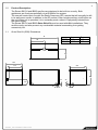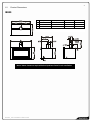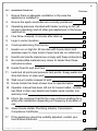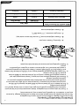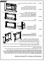
1
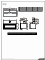
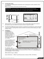
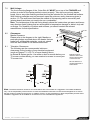
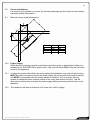
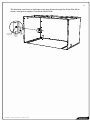
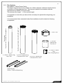
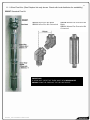
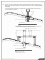
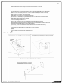
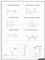
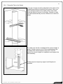
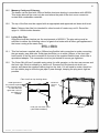
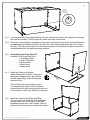
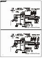
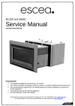
IB1100 and IB850 (Log Fire / Coal Fire) Installation Manual AUSTRALIAN EDITION Important: The appliance shall be installed in accordance with; This installation instruction booklet Local gas fitting regulations Municipal building codes Electrical wiring regulations AS/NZS 5601 Gas Installations Any other relevant statutory regulations. Must be installed by a qualified person Must be installed with an Outer Skin Kit (Separate Kit) This appliance is not intended for use by young children or infirm persons unless they have been adequately supervised by a responsible person to ensure that they can use the appliance safely. Young children should be supervised to ensure that they do not play with the appliance. Manufactured by: Escea Ltd, PO Box 5277 Dunedin NZ, Ph: +64 3 478 8220, email: [email protected] For contact details of your local escea distributor or dealer please visit www.escea.com.au 630185_6 IB Installation Manual AU 2 Note: THERE ARE A FEW THINGS TO CONSIDER BEFORE INSTALLATION Cavity Dimensions, Clearances, and fitting the Outer Skin Kit MUST be installed 100mm minimum off the floor Coupling of flue to fire Coupling of gas lines to fire Fixing the fire to the cavity Supply of electricity to fire Gas pipe placement to the front right of the cavity. The sequence you choose to do these tasks will vary on your individual scenario. Please read these instructions fully before proceeding with your installation. Leave the installation of the fascia panels until the very end of the installation and commissioning to avoid damage to the fascia panels. WARNING: Failure to follow these instructions could cause a malfunction of the heater, which could result in death, serious bodily injury, and/or property damage. Failure to follow these instructions may also void your fire insurance and/or warranty. Installation: Installation must be carried out by a registered installer who, on completion of the installation, must issue a certificate of compliance, in accordance with national and/or local codes. If a certificate of compliance is not issued then the Escea warranty may be void. This appliance needs fresh air for safe operation and must be installed with provisions for adequate combustion and ventilation air available to the room in which it is to be operating. Warranty Repair and Annual Servicing: Warranty repair work must be carried out by a recognised Escea Gas Fire Technician. It is recommended that recognised Escea Gas Fire Technicians are also used to carry out annual servicing requirements (particularly during the warranty period). For contact details of authorised Escea technicians in your area, please contact the retailer from whom the appliance was purchased. The heater must be installed according to these instructions and in compliance with all relevant building, gas fitting, electrical and other statutory regulations (eg. AS 5601). Any shortcomings in the appliance and flue installation will be the responsibility of the installer, and Escea will not be accountable for any such failings or their consequences. 630185_6 IB Installation Manual AU Contents: Product Description Section: 1.0 Creating the Cavity 2.0 Ventilation 3.0 Cavity Base 4.0 Hearth 5.0 Raised Installations Up a Wall 6.0 Wall Linings 7.0 Clearances 8.0 Corner Installations 9.0 Power Supply 10.0 Flue Kits 11.0 Flue Assembly 12.0 Laying Gas Pipe ___ 13.0 Assembling the Outer Skin Kit 14.0 Fixing the Outer Skin Kit (OSK) into the Cavity 15.0 Gas Fireplace Installation 16.0 Attaching the Flue to the Fireplace 17.0 Connecting the Gas Pipe 18.0 Fixing the Heater to the Base and Wall 19.0 Placing the fuel bed 20.0 Converting between fuel bed types ___________________21.0 Electrode Placement 22.0 Gas Type Conversion______________________________23.0 Checking Operating Pressure 24.0 Fitting the Fascia Panels 25.0 Locating Wall Mount Cradle for Wireless Control 26.0 Normal Operating Sounds and Smells 27.0 Installation Check List 28.0 Warranty Information 29.0 630185_6 IB Installation Manual AU 3 4 1.0 Product Description: The Escea IB1100 and IB850 gas fires are designed to be built into a cavity. Both appliances are flued conventionally via a Ø100mm flue system. The user will control their fire with the Radio Frequency (RF) remote that will normally be left in its wall mount cradle. In addition to the RF remote it has a single auxiliary on/off button on the unit. When not in operation it is in a standby mode unless it is physically isolated from the mains supply. The Escea IB1100 and IB850 Outer Skin Kit must be used with ALL installations. They seal the cavity and also prevent any combustible material surrounding from getting excessively hot. 1.1 Outer Skin Kit (OSK) Dimensions A IB850 IB1100 B A B 960mm 480mm 1260mm 630mm 345 565 565 475 560 45 48 190 62 630185_6 IB Installation Manual AU 145 1.2 5 Product Dimensions IB850 A B C Velo (3 sided) Velo (4 sided) 1060mm 1060mm 600mm 635mm 0mm 35mm Quadrato 1067mm 652mm 50mm Note: 30mm clearance required below Quadrato fascia for air ventilation 630185_6 IB Installation Manual AU Rado 985mm 560mm 0mm 6 IB1100 A B C Velo (3 sided) Velo (4 sided) 1360mm 1360mm 600mm 635mm 0mm 35mm Quadrato 1367mm 652mm 50mm Note: 30mm clearance required below Quadrato fascia for air ventilation 630185_6 IB Installation Manual AU Rado 1285mm 560mm 0mm 2.0 Creating the Cavity: The dimensioned drawing below shows the size of opening that must be created to fit the Outer Skin Kit. 7 Note: It is not necessary to line the side, top or back of the cavity. IMPORTANT: If you are installing an “Inset” Fascia (flush with the wall) these cavity dimensions are not applicable. Please refer to the Fascia Installation Manual supplied with your fascia or online at www.escea.com.au for specific cavity dimensions. Ideal Cavity Dimensions: All dimensions in millimetres B IB850 IB1100 A B C 960 1260 560 560 565 565 (Check Offset. Refer 2.2) A C 2.1 Where possible, it is recommended that the cavity is made slightly larger than the above dimensions to give the installer the maximum amount of space to work in. 2.2 The IB1100 and IB850 have their electronics compartment protruding from the left hand side of the fire and the resulting offset needs to be taken into account when installing into a tight masonry cavity. 3.0 Ventilation: It is important to remember that local building codes require additional ventilation be included into living spaces where open flued natural gas appliances are installed. Your local building codes provide formulae and tables for calculating the required ventilation given the size of the living space and the gas input of the appliance. Ceiling vent Be wary of adverse pressure differences if venting from ceiling spaces. Be wary of the effects of range hood or bathroom extractor fans etc... Add “make up air” ventilation to well sealed living spaces Wall vent For example, if you needed to size the wall vent as illustrated in the diagram above, the UK Council for Registered Gas Installers (CORGI) recommends an area of 500 mm2 for every kilowatt of input in excess of 7kW (25.2MJ/hr). IB850 & IB1100 Input = 40MJ/hr Area of Wall Vent = 500mm2 per kW input (net) in excess of 7kW (25.2 MJ/hr ) 630185_6 IB Installation Manual AU 8 Therefore excess = 40MJ/hr - 25.2 MJ/hr = 14.8 MJ/hr = 4.11 kW Wall Vent Opening = 4.11 x 500mm2 = 2055mm2 This is the minimum recommended wall vent required over and above any existing adventitious ventilation. 4.0 Cavity Base: This appliance MUST be fully supported on its base. The base must extend over the entire area of the underside of the appliance. The base must also be levelled to prevent vibration from possible fan imbalance. For the installation of an IB1100 the base of the cavity must be strong enough to support the total product weight, which is a minimum of 70kg. The base of the product must be fully supported at either side and at the centre front to back. 5.0 Hearth: A raised hearth can be of any size but must be constructed from non combustible materials. 5.1 NOTE: If the hearth is to be covered with tiles or some other veneer then the fire must be installed so that the base of the „Outer Skin Kit‟ is level with the finished top surface of the hearth. 6.0 Raising the Fire Up a Wall: This fire must be installed at a minimum of 100mm off the floor. If the fire is being located in such a way that the bottom of the cavity is any more than 100mm up off the ground no hearth is required. Escea recommend that if a heater is being mounted more than 100mm up a blank wall and no hearth is being used, then a four sided fascia is used (available from your Escea dealer). 630185_6 IB Installation Manual AU 9 7.0 8.0 8.1 Wall Linings: The front mounting flanges of the „Outer Skin Kit‟ MUST be on top of the FINISHED wall surface in order for the fascia panels to mount properly. Take into account any plaster board, tiles or any other finishing surface that may be intended for the finished wall surface. Wall finishing materials must not encroach upon the minimum cavity clearances given in section 1.0. The wall board that lines the outside of this opening can be normal dry wall (plaster board) and does not need to be non-combustible. Note: The temperature of the wall lining directly above the heater does get warm and hence may discolour paint finishes that are susceptible to temperature damage or distort vinyl wall coverings. For durability of finishes and surfaces you should contact the relevant manufacturer for their specification. Clearances: Mantle Clearance Please refer to the diagram to the right. Mantles or protruding ledges mounted above the heater that are made from combustible materials, must not extend from the wall outside of the dimensions shown. 100 300 200 Television Clearances The following are the recommended minimum clearances for the location of any electrical equipment (such as Plasma TV, LCD TV or home theatre) above an Escea IB Series gas fire. Use either a shelf or mantle below your TV screen or alternatively you can construct a recess to mount your TV screen into. 30 Maintain a 30mm clearance around the fascia to ensure ease of fascia removal. NB: No clearance is needed underneath 3 sided fascias Note: The above television clearance recommendations are to be treated as a suggestion of a suitable installation only. It is the responsibility of the end user to check the installation instructions of their electrical appliances to ensure that the location in relation to the gas fire, is suitable. Escea in no way guarantees or takes responsibility that the above installation suggestion will be suitable for all electrical or home entertainment appliances. 630185_6 IB Installation Manual AU 150 10 9.0 Corner Installations: If a cavity is to be created in a corner, the following drawings give the minimum sized interior wall and resultant flue position. 9.1 Minimum corner install dimensions: A B C D IB1100 1195 1260 565 600 IB850 1045 960 565 495 10.0 Power Supply: Whilst the cavity is being created consideration should be given to appropriate location of a standard 3 pin, EARTHED 240V power outlet. This must be within 0.5m of the rear left hand corner of the appliance. 10.1 Locating the power outlet within the cavity makes the installation very neat but the provision MUST be made to be able to switch the power supply off and on (electrical isolation switch) and MUST be accessible after the heater has been installed. This is normally done by means of a separate switch located outside of the cavity and wired to the plug. This will allow service technicians to isolate the power supply before performing service work on the appliance. 10.2 This appliance will draw a maximum of 2 Amps from a 240V supply. 630185_6 IB Installation Manual AU 11 The electrical cord (from an extension cord) should pass through the Outer Skin Kit as shown, through the supplied Cord Strain Relief Bush. Cord Strain Relief Bush Electrical Blanking Plate Electrical Cord 630185_6 IB Installation Manual AU 11.0 Flue Systems Non-Masonry Timber Frame Cavity: The heater must be flued to the outside via a 100mm diameter stainless steel flue that is covered by a 150mm diameter liner. This must be installed in accordance with the requirements of AS5601 and local codes. The minimum flue length = 3.6m vertical height 12 It is important to check that you have all the necessary flue parts before beginning your installation. Fixed by angle brackets, Outer Skin Kit and Cowl Free hanging Top sits in cowl, bottom sits on appliance It is recommended that a standard timber flue installation should include the following components: 4 x Ø100 x 900mm long 3 x Ø150 x 900mm long Galvanised Flue Liner 1 x Ø150 x 740mm long Inner Flue Galvanised Flue Liner Angle Bracing 25mm x 75mm x 600mm long 630185_6 IB Installation Manual AU 1 x Flue Cowl 1 x Ø180 x 200mm long Flue Sleeve 1 x Ø100 x 120mm long Flue Clamping Sleeve 11.1 Other Flue Kits- (Glen Dimplex kits only shown. Check with local distributor for availability) 13 552327 Standard Flue Kit 552332 Offset Flue Kit Black 552333 Offset Flue Kit Galvanised 552330 900mm Flue Extension Kit Black 552331 900mm Flue Extension Kit Galvanised IMPORTANT: IF USING A 45º OFFSET KIT THERE MUST BE A MINIMUM OF 600MM FROM THE FIREPLACE TO THE FIRST OFFSET. 630185_6 IB Installation Manual AU 14 12.0 Installing the Flue System: Non-Masonry Timber Frame Cavity: The heater must be flued to the outside via a 100mm diameter inner flue that is covered by a 150mm diameter liner. This must be installed in accordance with the requirements of AS5601 and local codes. The minimum flue length = 3.6m vertical height 12.1 Consult the installation instructions that come with your flue kit. To ensure safety the flue kit must be installed according to those instructions. An overview is provided below. Ensure all clearances to combustibles are maintained as per specifications earlier in this manual. It is important to check that you have all the necessary flue parts before beginning your installation. Gas Cowl 1. Locate the Outer Skin Kit in the cavity as per the instructions in section 15 of this manual. Mark the point for penetration that is directly above the centre of the flue outlet on the gas fireplace. Check that the location ensures that the flue outer liner maintains a 25mm clearance to all combustibles and timber framing. 2. Cut a 200mm square hole where the penetration is required using the mark created in step 1 as a guide. Fit non-combustible nogs in the ceiling space if required. 3. Measure the overall flue length required. Remember to allow for all necessary clearances to neighbouring structures (including a minimum of 600mm clearance above the nearest point on any part of the roof). It is recommended that extending the flue above the ridgeline will assist with down draught issues. Consult AS5601 2002 for further information. Outer Liner Ø150mm 4. Assemble all the outer liner lengths and fix together with pop rivets or self tapping screws. Lower the assembled outer liner through the roof (or false chimney) and secure to the fixed part of the Outer Skin Kit. Fix as necessary to inner framing where possible (see section 12.4). Ø100mm Inner Flue 5. Assemble the Ø100mm inner flue lengths using pop rivets or self tapping screws. It is recommended that all flue joints are sealed. Lower the Ø100mm inner flue assembly from the roof through the centre of the outer liner and locate onto the gas fireplace spigot. Ensure that the top of the Ø100mm inner flue is at the correct height at the top of the outer liner. 630185_6 IB Installation Manual AU 15 6. Fix an appropriate weather shielding to the outer liner at the penetration and seal to the roof or chimney using an appropriate sealer. 7. Fit the gas cowl. 8. Once gas fireplace is operational check the installation for flue spill where possible 9. Note: It is the installer‟s responsibility to ensure the installation complies with AS5601 2002 and all relevant local codes. 630185_6 IB Installation Manual AU 16 12.2 The top of the flue must be capped with an appropriate and approved anti down draft cowl. Note: As per national standards, the finished terminal must be in clear air and not enclosed in any way. All the required flue components are available from your Escea dealer in both kitset form and as individual components. 600mm clearance to nearest part of roof Seal - Deck Tight or similar Trimmers shown diagrammatic 25 Gap between flue shield and any timber 25 Angle fixing bracket supplied with flue kit. 100 150 DESIGN EXAMPLE ONLY LONG SECTION THROUGH FLUE ENCLOSURE Scale: NTS GENERAL CONSTRUCTION AND CLADDING SHOWN AND IS INDICATIVE ONLY ALL INSTALLATION & FLUING MUST COMPLY WITH AS 5601 200 min but allow for flue flashings at base 200mm min if another flue shares same enclosure deck-tite or similar flashing 100 trimmers shown diagrammatic gap between flue shield and any timber angle fixing bracket supplied with flue kit 150 25 25 ENCLOSURE DESIGN EXAMPLE ONLY LONG SECTION THROUGH FLUE ENCLOSURE Scale: NTS GENERAL CONSTRUCTION AND CLADDING SHOWN INDICATIVE ONLY 630185_6 IB Installation Manual AU 17 FROM AS5601, please ensure compliance to all other relevant sections of this code. 2.6.13 FLUE TERMINALS 2.6.13.1 Location The termination point of a flue shall be located in relation to any associated building and to neighbouring structures so that wind from any direction is not likely to create a downdraught in the flue or chimney. Except where 2.6.13.3 applies, a flue terminal shall: (a) Be at least 1m horizontally from a neighbouring structure; or (b) If less than 1m horizontally from a neighbouring structure, be at least 500mm above that structure; (c) Be at least 1.5m from any opening into a building; and (d) Be at least 200mm from another flue terminal. 2.6.13.2 Terminating a flue above a roof Where a flue is to terminate above: (a) A roof; the end of the flue shall be at least 500mm from the nearest part of the roof; (b) A trafficable roof designed for personal or public use, the end of the flue shall be at least 2m above the roof level and at least 500mm above any surrounding parapet; or (c) A chimney, the end of the flue shall be at least 200mm from the nearest part of the chimney. NOTE(1) The distance is measured before the cowl is fitted to the end of the flue (2) (NA) (3) (NA) 12.3 2.6.13.3 Location of a flue terminal other than above a roof (NA) Flue Clearance: 630185_6 IB Installation Manual AU 18 630185_6 IB Installation Manual AU 12.4 19 Fixing the Flue to the Cavity A length of angle should be attached to the inside of the timber frame cavity to hold the flue in place. Once you have fixed the angle to the inside of the cavity holes must be drilled to secure it to the flue. Screws or rivets can be inserted directly into the 150mm flue to hold it in place. To make sure the flue is installed at the correct height, a piece of timber can be cut to 570mm and between the fire base level and the bottom of the flue. This will ensure the correct height for installation and support the flue assembly. Timber prop as temporary support until fireplace is installed. 630185_6 IB Installation Manual AU 20 12.5 Masonry Cavity and Chimney: The heater can be flued with 100mm flexible aluminum ducting in accordance with AS5601. This single skinned flue must only be used where the path of the duct never comes into contact with combustible materials. 12.6 The top of the flue must be capped with an appropriate and approved anti down draft cowl. Note: Chimney liner flue kits intended for other brands of heater may not fit. Escea flue spigot is 100mm inside diameter. 13.0 Laying Gas Pipe: Gas pipe should be sized as per the requirements of AS5601. The pipe sizing must be sufficient to deliver the following volume of gas to the heater with all other gas appliances in the home running at the same time; IB850 = 40MJ/hr IB1100 = 40MJ/hr 13.1 This fire has been supplied with a 300mm long flexible inlet connection to make connecting the gas supply easy and safe. Solid pipe should be run to within 100mm of the front right hand corner of the fire and connected to the end of the supplied flexible hose, which has a specialised adaptor. This connection must be joint tested to ensure gas tightness. 13.2 The Outer Skin Kit has 3 possible entry points for solid gas pipe, on the two rear corners and the front right. Each is sealed by a „knock-out‟. Remove only the knock-out which you require, and place the supplied rubber plug into the hole. You will need to make a small cut into the rubber plug to allow the gas pipe to pass through, keeping the plug as air-tight as possible. Plan view from top looking down. Electrical point of entry. Install gas lines to any of these 3 points. Leave enough piping to reach the front right hand corner of the OSK once installed. Final gas connection point (after OSK installation) 630185_6 IB Installation Manual AU Gas pipe 21 Split plug as indicated to allow gas pipe to pass through 13.3 It is recommended that a gas isolating valve be installed as close to the regulator on the gas inlet side as possible. This will allow for easier servicing in the future. 13.4 If the room has not been completed and the wall surfaces are yet to be lined or plastered the fire must not be installed into the Outer Skin Kit until such time that there will be no further sanding. This will prevent dust from entering the product. Preferably the fireplace should be commissioned after the walls have been painted. 14.0 Assembling the Outer Skin Kit: Included in the Outer Skin Kit is: - 1x Top-Rear panel - 1x Top-Front panel - 2x Side panels - 1x Rear panel - 1x Base panel 14.1 Attach the Sides to the Base: Attach Side panels to Base, make sure Base panel flanges are on the outside, and the large flange of the Side panels faces the front. The Left Side has a rectangular cutout, It is important that this is on the left hand side and that the right hand circular knock-out is at the base of the Outer Skin Kit as pictured. 14.2 Attach the Rear to the Sides and Base: The rear panel fits inside the Side and Base panels, make sure the flanges on the Side and Base panels are on the outside. The two holes on the Rear panel go towards the bottom. 630185_6 IB Installation Manual AU FR O NT 22 14.3 Attach the Top-Rear: Attach the top-rear panel to the Sides and Rear panels, with the flanges of the Top-rear panel on the outside. Do not attach Top-Front panel yet, this will be done after the flue has been mated with the fire. 15.0 Fixing the Outer Skin Kit into the Cavity: Slide the Outer Skin Kit into the cavity, and secure it to the wall using screws or other fasteners through the slots at the front of the side panels. The cavity is now ready for the installation of the Gas Fireplace. 630185_6 IB Installation Manual AU 16.0 23 Gas Fireplace Installation: Attached to the base of the Outer Skin Kit are guide rails. The inside edge of these rails will line up with the outside edge of the two outer under base supports. When the parts are lined up, push the fire towards the back of the Outer Skin Kit until it cannot be pushed back any further. The front of the firebox should now be sitting flush with the OSK. 16.1 Removing the Front Glass: Step 1: Unscrew the side and top glass retainers and remove them. Take care that the glass does not fall forwards at this stage Step 2: Lift out glass and place it carefully aside. 630185_6 IB Installation Manual AU 24 Step 3: Remove the top of the heater outer shell. Take out the screw from each side (as shown below), lift and pull the top of heater shell out towards yourself. Undo screws from both sides Step 3: For best access we recommend removing the fire box. Undo the four screws on the front four corners of the fire box and the two screws on the inside holding down the fire box (as shown below). Pull the fire box out of the heater. 630185_6 IB Installation Manual AU 25 17.0 Attaching the Flue to the Fireplace: Once the gas fireplace has been inserted into the OSK and the firebox removed, the flue can be attached. To do this line up the 100mm flue with the flue outlet spigot and drop the flue into the spigot. Note: To increase access through the fire to reach the flue connection, remove firebox and lid. 17.1 Once the flue is installed, the top-front of the Outer Skin Kit can be installed by sliding it into position as shown above. The Top-Front should sit ontop of the Outer Skin Kit sides and be pushed in until the front sits flush and can be screwed in place on each side. Please consider how the fire will be fixed to the base before installing. Refer to 19.0 for details 18.0 Connecting the Gas Pipe: When the heater has been pushed back into position the gas pipe can be connected to the inlet side of the appliance regulator at the front RH corner of the heater. The pipe assembly should have already been tested as per section 22.0 18.1 The regulator that is supplied with the fire MUST NOT BE REMOVED. Removal of the regulator, or replacing it with one not intended for use with an Escea fire, will void the limited appliance warranty. 630185_6 IB Installation Manual AU 26 Note: Refer to 13.2 for further gas pipe laying information as per diagram below Plan view from top looking down. Electrical point of entry. Install gas lines to any of these 3 points. Leave enough piping to reach the front right hand corner of the OSK once installed. Final gas connection point (after OSK installation) Gas pipe 19.0 Fixing the Heater to the Base and Wall: There are several ways that the heater can be fixed against movement: It is a requirement that this heater be securely fastened to the wall and base. Note: It is important that the outer fascia is used during this process to ensure that the heater is located in the appropriate position within the cavity. 19.1 Fixing Heater to Base: The heater has two holes along the front edge of the base panel that have been provided to allow installers to screw the heater to the floor. Because of a lack of access for drilling it may be necessary to mark the appropriate location for these screws and then remove the heater and drill holes through the bottom of the Outer Skin Kit into hard flooring. Alternatively a socket set can be used to drive in hex headed screws. 630185_6 IB Installation Manual AU 19.2 27 Fixing Heater to Wall: The installer must also fix the heater to the sides of the cavity using the bracket kit provided. These brackets are attached through the flanges on the side of the Outer Skin Kit. The flanges of the Outer Skin Kit must be installed over the outer lining surface of the wall i.e. over the Plaster Board rather than onto a stud which is then subsequently covered with a wall lining. Otherwise the fire will be sitting too far back and will inhibit the outer Fascia panel from fitting correctly. 630185_6 IB Installation Manual AU 20.0 Placing the fuel bed: After replacing the firebox (if removed in 16.1) the fuel bed media can now be placed. → If you are installing logs into an IB600 or IB850 → If you are installing logs into an IB1100 → If you are installing a ceramic coal fuel bed → If you are converting from logs to coals → If you are converting from coals to logs 20.1 28 SEE SECTION 20.1 SEE SECTION 20.2 SEE SECTION 20.3 SEE SECTION 21.1 SEE SECTION 21.2 IB850: Locating the Log Set After Replacing the Firebox: 1) Remove packaging from around log sets 2) Place rear log (long rectangular one) into position by inserting it in behind retainer bracket at rear of fire box. 3) Place front three log sets into position on the log retaining brackets, over the top of the main burners. The front edge of each log should be located so that its front edge is directly behind the holes in the top of each burner which should follow the contours of the logs. 2) 3a) 3b) 3c) 3d) Align logs to burner holes. 630185_6 IB Installation Manual AU 29 IB850 Log & Template Position 4) Line up some of the coals that have been supplied with this appliance, along the burner holes in front of the logs. 5) Scatter the remaining coals around to fill the empty spaces left over. 630185_6 IB Installation Manual AU 20.2 30 IB1100: Locating the Log Set After Replacing the Firebox: 1) Remove packaging from around log sets 2) Place rear logs (2 x long, rectangular logs) into position by inserting them in behind retainer brackets. 3) Place front four log sets into position on the log retaining brackets, over the top of the main burners. The front edge of each log should be located so that its front edge is directly behind the holes in the top of each burner (with approximately 5mm clearance) which should follow the contours of the logs. 2) 3) 3a) 3b) 3c) 3d) Align logs to burner holes 4) Cover empty spaces around logs on the front burner ONLY with small coals as provided. It is important that coals are not placed on the rear burner at all. 630185_6 IB Installation Manual AU 20.3 31 Placing ceramic coal fuel beds: Spread the supplied ceramic stones evenly across the firebox base as shown on the following page, ensuring that there is only one layer of stones – More than one layer of stones will result in reduced flame efficiency. Make sure the Flame Sensing and Spark Ignition rods are clear of stones to prevent ignition failure. 20.4 Log or Coal Replacement: The fire unit should never be used with broken logs or coals. Turn off the fire and allow the unit to cool before removing the glass to carefully remove the logs or coals. If for any reason a log should need replacement, you must use the proper replacement log. The position of these logs must be as shown in the diagrams on the previous page, and the position of coals must comply with section 21.3 on the previous page. Note: Improper positioning of logs may create carbon build-up and will alter the unit’s performance. Malfunctioning due to improper log placement is not covered under warranty. 21.0 Converting between fuel bed types The fireplace is configured to operate with the supplied fuel bed only. If conversion to a different fuel bed type is desired, a conversion kit (Including new burners) is required. Always use gloves when handling the fascia. 21.1 Converting from Logs to Coals Step 1: Remove the fascia and glass to provide access to the fuel bed if you have not already done so. Remove and discard of the existing logs and any small coals. Always ensure the fireplace has cooled completely before attempting to access the firebox. Step 2: Remove and discard the Log Template (which is located on top of the burners and holds the logs in place) by unscrewing it on the left and right lower sides of the firebox. Step 3: Remove the firebox as described in section 17.0 of this install manual. Step 4: Remove by unscrewing and discard the Rear Log Retainers as shown in the image to the right. There will be 2x Rear Log Retainers on the IB600 and IB850, and 4x on the IB1100 - Remove all of these. 630185_6 IB Installation Manual AU Rear Log Retainer Step 5: Replace the firebox by reversing the instructions in section 17.0 of this manual (do not replace the glass yet) 32 Step 6: Remove and discard the front and middle burners as described in section 24.1 and 24.2 of this manual. To do this you will need to detach the Spark Electrode Assembly. If your fire is set to operate on Natural Gas, you will need to remove the burner collars (shown right) from the removed burners and attach them to the supplied burners, as described in section 24.5 of this install manual. NG Step 7: Install the burners supplied with your conversion kit and re-attach the Spark Electrode Assembly. Ensure the Spark Electrode Assembly complies with the guidelines in section 23.0 of this install manual. If using Natural Gas, remember to re-attach the burner collar taken from the replaced burners and pictured above. Step 8: Install the coal fuel bed as per section 20.3 of this installation manual. 21.2 Converting from Coals to Logs Step 1: Remove the fascia and glass to provide access to the fuel bed if you have not already done so. Remove and discard of the existing ceramic coals. Always ensure the fireplace has cooled completely before attempting to access the firebox. Step 2: Remove and discard the front and middle burners as described in section 24.1 and 24.2 of this manual. To do this you will need to detach the Spark Electrode Assembly. If your fire is set to operate on Natural Gas, you will need to remove the burner collars (shown top right of this page) from the removed burners and attach them to the supplied burners, as described in section 24.5 of this install manual. Step 3: Remove the firebox as described in section 17.0 of this install manual. Step 4: Once the firebox is removed, attach the Rear Log Retainers using a screwdriver as shown right. The IB600 and IB850 have 2x Rear Log Retainers, which should be screwed in place in the rear corners of the firebox. The IB1100 has 4x Rear Log Retainers, two in the rear corners of the firebox and two in the center as shown. Ensure brackets are facing upwards and in the orientation shown to the right. Rear Log Retainer IB600 & IB850 Step 5: Install the burners supplied with your conversion kit and re-attach the Spark Electrode Assembly. Ensure the Spark Electrode Assembly complies with the guidelines in section 23.0 of this install manual. If using Natural Gas, remember to re-attach the burner collar taken from the replaced burners and pictured above. 630185_6 IB Installation Manual AU IB1100 33 Step 6: Replace the firebox by reversing the instructions in section 17.0 of this manual (do not replace the glass yet). Step 7: Attach the Log Template at the left hand side, using the existing screw which is holding the middle burner in place. Remove this screw and re-attach with the log bracket in place. To attach to the right hand side, use the supplied screw and brass washer as shown in the diagrams below. In some cases it may be necessary to drill a 1/8” (3.3mm) hole in the lower baffle. Note, the diagram below is for an IB1100. For IB850 and IB600 the log templates shape will vary. Step 8: Install the log fuel bed as per instructions in section 20.1 or 20.2 of this installation manual. 22.0 Electrode Placement: The placement of the electrodes is CRITICAL to the operation of the fire. These are factory set but if the event that they are moved during installation or the fire is having trouble lighting or staying lit then below is a guide to electrode placement. Ensure no logs or coals are touching the electrodes. 630185_6 IB Installation Manual AU 23.0 34 Gas Type Conversion: THIS APPLIANCE IS CONFIGURED TO OPERATE ON NATURAL GAS For conversion to Propane, use the following instructions. Your gas fire has been supplied with the necessary parts for gas conversion. Follow the steps on the following page to change from NG to Propane (or vice versa). Step 2 Remove Screws 23.1 Step 1: Remove inner fascia, glass and logs (as described earlier in this manual). Installer may also wish to remove the firebox to increase the work space within the heater. 23.2 Step 2: Take out front two burners by removing the screws from the left hand end of the burner top face. Unscrew the electrodes attached to front burner. Burners can then be lifted out. 23.3 Step 3: (IB850 only) Unscrew rear burner clamp bracket on left side. Lift out the rear burner. 23.4 Step 4: Change the three jets (two jets in IB1100) with the jets supplied in kitset (outlined in the table below). Step 3 Step 4 Replace the rear burner and clamp bracket (IB850 only). Reattach the spark electrodes to the front burner. PROPANE IB850 (Logs) IB850-C (Coals) IB1100 (Logs) IB1100-C (Coals) NATURAL GAS IB850 (Logs) IB850-C (Coals) IB1100 (Logs) IB1100-C (Coals) Front Jet (mm) 1.18 1.18 1.40 1.40 Middle Jet (mm) 1.05 1.05 Rear Jet (mm) 1.10 1.10 1.25 1.25 Front Aeration Collar 11mmØ 11mmØ 11mmØ 11mmØ Middle Aeration Collar 11mmØ 11mmØ Rear Aeration Collar Front Jet (mm) 2.30 2.30 2.65 2.65 Middle Jet (mm) 2.10 2.10 Rear Jet (mm) 2.10 2.10 2.40 2.40 Front Aeration Collar 6.5mmØ 4.0mmØ 6.5mmØ 4.0mmØ Middle Aeration Collar 6.5mmØ 4.0mmØ Rear Aeration Collar 630185_6 IB Installation Manual AU 11mmØ 11mmØ 7.0mmØ 4.0mmØ 23.5 35 Step 5: If changing from Propane to NG, slide the supplied burner collar onto the burner tubes of both burners as shown to the right and secure in place using the supplied screw as shown If changing from NG to Propane, remove the burner collar by removing the screw and completely removing the burner collar. 23.6 Step 6: Your fire will have either regulator A (Maxitrol) or regulator B (Beckley) as shown below B A For regulator A: Take the regulator spring out of the regulator by unscrewing the regulator cap and white pressure adjustment screw completely. Swap regulator spring with the new spring that is supplied in conversion kitset. The NG spring is unpainted, the Propane spring is painted blue. Replace white adjustment screw and regulator cap. For regulator B: Take the regulator spring out of the regulator by unscrewing the pressure adjustment knob completely. Swap regulator spring with the new spring that is supplied in conversion kitset. The Propane spring is painted green, and the NG spring is painted purple. Replace adjustment knob. 23.7 Step 7: Reset gas pressure as per instructions in this installation manual. 23.8 Step 8: Cover the existing gas type label with the new gas type label supplied in kitset. Ensure serial number and date of manufacture are still visible. Write your name, company (if appropriate) and date of conversion on new label with permanent marker. Replace firebox and fuel media. 630185_6 IB Installation Manual AU Step 8 24.0 36 Checking Operating Pressure: WARNING: The regulator that is supplied with the fire MUST NOT BE REMOVED. Removal of the regulator, or replacing it with one not intended for use with an Escea fire, will void the limited appliance warranty. This is done at the regulator located at the front RH corner of the appliance. This is best done before the fascia panels have been fitted to avoid fascia damage. A pressure test point is available for the operating test pressure only (as shown below). Your fire will be supplied with one of the following regulators: B A D A C C Maxitrol Beckley A = Operating Pressure test point B = Pressure adjustment screw (To access on Maxitrol first remove metal cap) C = Inlet gas connection ( ½” Female BSPT) D = Pressure adjustment screw 1) Check the inlet pressure to the appliance. Attach manometer tube to the first test point upstream of the appliance (typically at the gas utility meter or auto change device for a propane bottle station) 2) Run the heater on full (all burners running) and measure inlet pressure with all the other gas appliances running. If pressure does not fall within the maximum or minimum pressures listed on the table below then reassess installation pipe size or upstream regulator settings. 3) Remove the operating pressure test point grub screw. Connect manometer tube and measure pressure with heater running on full (all three burners running) and with all the other gas appliances running. 4) The heater regulator pressure has been factory set to 0.87kPa for Natural Gas heaters and 2.30kPa for Propane heaters. Please check that the operating pressure is exactly as listed and if not, adjust screw in centre of regulator until pressure is correct. 5) Replace operating test point screw and leak test test point. IB1100 and IB850 Pressure Table Minimum Inlet Pressure Maximum Inlet Pressure Operating Pressure Gas Type Propane 2.5kPa 5.0kPa 2.30kPa Natural 1.2kPa 5.0kPa 0.87kPa Note: If this appliance cannot be adjusted to perform correctly during installation, please refer to the appliance distributor. For contact details of your local escea distributor or dealer please visit www.escea.com.au 630185_6 IB Installation Manual AU 25.0 37 Fitting the Fascia Panels: To avoid scratches or knocks to the fascia panels of this heater they must be fitted at the complete conclusion of the installation process. It may be necessary to use the outer fascia to initially locate the heater but then remove it again so that there is no chance of damage. Note: Never Ever Rub the Fascia Panels. Step 1: Replace the glass and retaining brackets. Note: If the glass gasket requires a replacement, call your nearest Escea agent who will ensure the part is replaced with the correct type. In the event that the glass is broken by impact, purchase the replacement from an authorised Escea agent only. Step 2: Hang the outer fascia (larger one) from the lip that extends at the top of the heater at 45 degrees. If hanging a 4 sided fascia please Refer to sections 22.1 and 22.2 on the next page. Step 3: Fit the two screws at the base of each side of this fascia. The heater may have to be adjusted in or out of the cavity to ensure fascia fits correctly. Step 4: Hang the top edge of the inner fascia (smaller one) from the lip that extends at 45 degrees from the top of the firebox. Fit the two screws through the brackets at the bottom of the inner fascia to retain inner fascia panel. Step 5: Place the bottom fascia trim into position. This panel is held on with magnets. If this panel does not fit, adjust the outer Fascia side to side or the heater in/out until the trim fits well. 630185_6 IB Installation Manual AU 25.1 When installing a 4 sided fascia ensure that the clips that the outer fascia screw into are at the bottom of the slot on which they are attached as shown below. The outer fascia should be pushed down onto the top lip so that it is as low as possible and the screw holes in the fascia line up with the lowered clips. Top lip 26.0 Locating Wall Mount Cradle for Wireless Control; The heater‟s remote contains the thermostat that will sense the room temperature and communicate this back to the heater via radio frequency. A wall mount cradle has been provided for the wireless control and where possible the control should be housed in this cradle. The location of this cradle should be decided by taking into account the following factors; 1. Simple, convenient access for the user 2. Away from air flow and drafts through the room 3. The parts of the room that people are likely to spend time 4. Away from direct sun light 5. A suitable distance away from the heater. 6. Ideally 1.2m to 1.5m from the floor The radio frequency signal will go through some walls but for best results Escea suggest that the cradle position is between 5 and 15 metres away from the heater. The best height off the ground to locate the cradle is about chest height. This gives a good average room temperature and easy access for the user. Please ensure that cradle is screwed firmly onto wall using the screws provided. 630185_6 IB Installation Manual AU 38 27.0 Normal Operating Sounds and Smells; 39 Note: Each time the fire is lit from cold the glass may fog up with condensation. This is normal and the condensation will disappear within a few minutes once the glass heats up. 27.1 Sounds It is possible that you will hear some sounds from your gas appliance. This is perfectly normal due to the fact that there various types of materials and parts used within your appliance. Listed below are some examples. These are all normal operating sounds and should not be considered as defects in your appliance. Fan: Escea gas appliances use electric fans to push heated air further into the room. It is not unusual for the fan to make a “whirring” sound when ON. This sound will increase or decrease in volume depending on the speed setting of your fan. Gas Control Valve: As the gas control valves turn ON and OFF, a dull clicking sound may be audible, this is the normal operation of a valve. When the fire is switched off after being run for a while, there may be popping and fluttering noises as the residual gas in the burner burns away. These are normal and should be no cause for concern. Unit Body/Firebox: Different types and thicknesses of steel will expand and contract at different rates resulting in some “cracking” and “ticking” sounds being heard throughout heating and cool down processes. 27. 2 Smells: The first few times the unit is operated, the unit may release an odour and the flames may appear orange caused by the curing of the paint, the burning off of the starch in the gas logs and the oils in the metal. This is a temporary curing process which will disappear with use. A deposit on the inside of the glass, caused by the starch in the logs, may appear as a build up after several uses. If this film is not removed, it wil bake on and may become difficult to remove. When the glass is cold, remove it (see section 16.1) and clean the inside with a non-abrasive cleaner. DO NOT ATTEMPT TO CLEAN THE GLASS WHILE IT IS HOT. NEVER OPERATE THE UNIT WITH THE GLASS REMOVED. 630185_6 IB Installation Manual AU 40 28.0 Installation Check List: 1 Ensure there is adequate ventilation in the area the appliance is installed in. 2 Ensure the spark electrodes are correctly positioned. 3 Operating pressure checked with heater running on full (all burners operating) and all other gas appliances in the house switched on. 4 Flue Draw checked, 5 minutes after start up. 5 Logs in correct position. 6 Coals spread along front burner. 7 Heater run on high for 60 minutes with house doors and windows open to clear smell of paint and oils on initial burn._ 8 Hearth and mantle clearances comply with these instructions. 9 No combustible materials any closer to heater than these instructions allow. Tick here 10 Heater fixed to wall and floor. 11 Leak test all joints and pressure test points. Soapy water and drop test done on pipe work. 12 Wall mount cradle screwed to wall. 13 House holder has been shown how to operate heater. 14 Operator manual has been left out for house holder, installer has filled in their own details and heater serial number into warranty card. 15 Inform the customer that the fire may continue smelling for a while after installation depending on frequency & duration of use 16 Given House Holder Plumbing Industry Commission Compliance Certificate.______________________________ 17 If the appliance cannot be suitably adjusted, contact your local Escea distributor. ______________________________ 630185_6 IB Installation Manual AU 41 29.0 Escea Product Warranty 1 This document sets out the express warranties that apply in respect of Escea products purchased in either: (a) Australia with the exception of Western Australia, provided by Glen Dimplex Australia Pty Limited ABN 69 118 275 460 of Unit 2, 205 Abbotts Road, Dandenong, Victoria 3175 (Phone number 1300 556 816) (we, us our). (b) Western Australia, provided by Airgroup Australia of 28 Division Street, Welshpool, Perth, WA 6106 (Phone number 893 502 200) (we, us our). The express warranties in this document apply to the particular Escea product which this warranty card has been included in the packaging for or otherwise supplied with (the Escea product). 2 Escea express warranty Subject to the exclusions in section 3, we warrant under this express warranty that the below parts of the Escea product will be free from defects of materials or workmanship for the periods specified below (with each of the below periods commencing on the date the Escea product was purchased by you as a brand new product from a retailer located in the regions outlined in section 1): Part Type of express warranty Firebox and Heat Exchanger 10 years parts and labour warranty* All other parts 1 year parts and labour warranty followed immediately by 1 year parts only warranty* * Where a Escea product is covered by a parts and labour warranty, the warranty covers both the repair of the defective part or the provision of a spare part to replace the defective part and the installation of that part. ** Where a Escea product is covered by a parts only warranty, the warranty covers only the repair of the defective part or the provision of a spare part to replace the defective part and does not include the removal of the defective part or the installation of the repaired or replaced part. This express warranty is personal to the first person who acquires the Escea product from the relevant retailer and claims under this warranty cannot be made by anyone other than this person. The benefits conferred by this express warranty are in addition to the Consumer Guarantees referred to in section 4 and any other statutory rights you may have under the Australian Consumer Law and/or other applicable laws. 630185_6 IB Installation Manual AU 3 Warranty exclusions 42 This express warranty does not apply where: (a) the Escea product has been installed, used or operated otherwise than in accordance with the product manual or other similar documentation provided to you with the Escea product; (b) the Escea product requires repairs due to damage resulting from accident, misuse, incorrect installation, cleaning or maintenance, unauthorised modification, tampering or unauthorised repairs by any persons, use of defective or incompatible accessories or exposure to abnormally corrosive conditions; (c) the defective part relates to a consumable part of the Escea product which require routine replacement; (d) you are unable to provide us with reasonable proof of purchase for the Escea product; (e) the breakdown occurs after the expiry of the express warranty period set out in section 2; or (f) the Escea product was not purchased in any of the regions outlined in section 1 as a brand new product. ESCEA is not responsible for any staining or smoke damage caused by flue products discharged through the flue cowl. 4 Consumer Guarantees Our goods come with guarantees that cannot be excluded under the Australian Consumer Law. You are entitled to a replacement or refund for a major failure and for compensation for any other reasonably foreseeable loss or damage. You are also entitled to have the goods repaired or replaced if the goods fail to be of acceptable quality and the failure does not amount to a major failure. 5 How to make a claim You may make a claim under this warranty by contacting us by: For Australia with the exception of Western Australia, visiting www.glendimplex.com.au, contacting our customer care line (1300 556 816) or visiting a Glen Dimplex service centre. For Western Australia, visiting www.airgroup.com.au, contacting us on 8 9350 2200. To make a valid claim under this warranty, you must: (a) lodge the claim with us as soon as possible and no later than 14 days after you first become aware of the breakdown; (b) provide us with the Escea product serial number; (c) provide us with reasonable proof of purchase for the Escea product; and (d) if required by us, provide us (or any person nominated by us) with access to the premises at which the Escea product is located at times nominated by us (so that we can inspect the Escea product). 630185_6 IB Installation Manual AU 6 Warranty claims 43 If you make a valid claim under a parts and labour warranty and none of the exclusions set out in section 3 apply, we will, at our election, either: (a) repair the relevant part of the Escea product; or (b) replace the relevant part of the Escea product with a product of identical specification (or where the product is superseded or no longer in stock, with a product of as close a specification as possible). We will also arrange for the relevant repaired or replacement part to be installed at no charge to you. If you make a valid claim under a parts only warranty and none of the exclusions set out in section 3 apply, we will, at our election, repair or replace the relevant part. You acknowledge that installation is not covered under a parts only warranty, however, we may, for a fee, install the repaired or replacement part for you. We will, on request, provide you with a quote for the installation of the repaired or replacement part. Goods presented for repair may be replaced by refurbished goods of the same type rather than being repaired. Refurbished parts may be used to repair the goods. Escea products are designed and supplied for normal domestic use. We will not be liable to you under this warranty for business loss or damage of any kind whatsoever. 7 Costs of warranty claim in Australia (excluding Western Australia) Where you make a claim under this warranty, an authorised repairer may need to attend your premises to inspect the Escea product. We may charge you a service call fee if a repairer will be required to travel more than 30 kilometers from the nearest Glen Dimplex service centre to your location. You may obtain details on the location of our service centres and our service call fees by visiting our website (www.glendimplex.com.au) or calling our customer care line (1300 556 816). 630185_6 IB Installation Manual AU 12 630185_4 IB Service Manual AU 12 630185_4 IB Service Manual AU Wiring Diagram IB850: 18VAC 240 VAC 11 Part No. 620125_3 i Wiring Diagram IB1100: 18VAC Part No. 620140_3 240 VAC i 630185_4 IB Service Manual AU Annual service procedure: 10 1. Isolate power to fire. 2. Remove front glass and clean inside of glass. 3. Remove logs and brush off any soot. 4. Remove burners and blow compressed air through the burner ports. 5. Remove jets and clean injector hole with solvent. 6. Remove firebox to give access to fan, brush and vacuum any dust build up from fan blades. 7. Vacuum any dust from the cavity that houses the fan and solenoid valves and from the ducts down each side of the heater that lead to this cavity. 8. If the gas piping includes a flexible hose connected to the regulator, check the hose for signs of wear (discolouration, loss of flexibility, cuts, worn covers, cracks, crushing, kinking, flattening or loose end fittings) and replace if worn, or more than five years old. 9. Test all joints for gas tightness. 10. Reassemble heater and check that operating pressure is correct. 2.3kPa Propane, 0.87kPa Natural Gas with all burners running. 11. Check glass & firebox tape and replace if necessary. 11. Check to make sure that flue system is intact and not in any way blocked. Check the flue draw with a smoke match to confirm there is no spillage from the draught diverter. 12. Trial heater with several start/stop cycles and trial fan-boost, flame effect only and thermostat modes to ensure that all modes function correctly. 630185_4 IB Service Manual AU Replacing Over-Temperature Cutout Devices: 9 There are 2 Over-Temperature cut-out devices on this appliance; - One cut-out device is on the lid of the fireplace, which is accessible by removing the fascia and then the fireplace lid as described in the “Gas Fireplace Installation” section of the Installation Manual and one cut-out device on the rear hood, which is accessible by removing the fireplace from the cavity. Replacement Cutout Devices are available from your Escea retailer and can be replaced by drilling out the rivets securing them in place. Replaced Cutout Devices must only be replaced by parts of exact same value and specification. Replacing a Wireless Control: If the wireless control becomes lost or damaged, a new one can be ordered from any Escea retail agent. When you have the new remote, the following procedure needs to be followed to “teach” the remote to only communicate with that fire. 1. Ensure the fire and remote are set to “Off” (only the time is displayed on the remote). 2. Press the – (minus), + (plus) and the Fan Boost buttons simultaneously until all the characters on the display light up. This will put the remote into test mode and the two large temperature digits should be reading 00. FLAME EFFECT ONLY C SET FAN BOOST TIM ER 3. Press and hold the – (minus) button until the two large temperature digits reading 00 start to flash slowly. Release the – (minus) button. The remote control is now ready to be addressed to the fire. R SE LE CT ME TI ACT TE I VA SET TIME 4. Press and hold the red auxiliary on/off button on the fireplace for a minimum of eight seconds, or until the two large temperature digits start counting upwards from 00 to 99 repeatedly. Red auxiliary Button Note: Pressing the red auxiliary button on/off button will start the fire. Once the remote control is counting the fire can be turned off by pressing the red auxiliary button again. 5. Press the large power button in the middle of the remote control to exit the test mode and return to normal operation. The remote should only be displaying the time. Check the fire will start using the remote control by pressing the large power button. Turn it off again using the remote control. 6. The fire is now re-addressed to the remote control. 630185_4 IB Service Manual AU Replacing Electronic Drawer / Components 8 ISOLATE THE POWER TO THE FIRE BEFORE PROCEDURE. All of the electronic components of the heater have been located on a removable drawer. This drawer is located on the left hand outer side of the IB850 and IB1100. On the back of the drawer are two large connectors that unplug as the drawer is removed so only the three wires connecting the electronics to the ignition and flame rods must be removed manually from the PCB (Printed Circuit Board). Step one: Remove outer fascia by taking out two screws located behind the bottom fascia trim panel. Step Two: Take out the two screws at each end of the electronic drawer and pull drawer directly outwards. Step Three: Carefully remove the two wires shown from the white ignition module. Wire Entry: IB850 & IB1100 1. Flame Rod 2. Spark Lead Note: It is important that the flame rod & spark lead wires sit in this position in the electronic tray. 630185_4 IB Service Manual AU Removing / Cleaning Fan or Replacing Firebox 7 As part of regular service procedure, it is recommended that the fan is removed for cleaning. Dust will build up on the fan rotor and in the cavity where the fan is located. This can be removed by the service person using a hearth brush and a vacuum cleaner. The Heat Exchanger assembly is non-field serviceable and needs to be replaced as part of the firebox assembly. Contact your Escea distributor for more information. Step One: ISOLATE THE POWER TO THE FIRE BEFORE PROCEDURE Remove front glass, log set and log bracket as described on page 5. To remove the log bracket take out the screws securing it to the firebox. Remove screws from each corner of firebox Step Two: Remove firebox from heater by taking out the two screws attaching the front lid + the screws in each corner of the firebox. Then remove the screws in the base of the firebox, and pull fire directly outwards (as shown). Remove screws from firebox base, lift lid and pull firebox out Step Three: Take out the 7 screws on top of fan plate assembly. Step Four: Lift the fan unit up and out as far as the wiring loom will allow. Unplug wires to fully remove fan assembly. Step Five: Clean fans and area around valves, removing all dust build up. Replace fans and fire box. Step Six: To replace fan assembly and firebox repeat these steps in reverse order. Pull up and outwards 630185_4 IB Service Manual AU Checking Operating Pressure: 6 This is done at the regulator located at the front RH corner of the appliance. This is best done before the fascia panels have been fitted to avoid fascia damage. A pressure test point is available for the operating test pressure only (as shown below). 1) Check the inlet pressure to the appliance. Attach manometer tube to the first test point upstream of the appliance (typically at the gas utility meter or auto change device for a propane bottle station) 2) Run the heater on full (all three burners for IB850 and two burners for IB1100 are running) and measure inlet pressure. If pressure does not fall within the maximum or minimum pressures listed on the table below then reassess installation pipe size or upstream regulator settings. 3) Remove the operating pressure test point screw. Connect manometer tube and measure pressure with heater running on full (all three burners for IB850 and two burners for IB1100 are running). 4) The heater regulator pressure has been factory set to 0.87kPa for Natural Gas heaters and 2.30Kpa for LPG (PROPANE) heaters. Please check that the operating pressure is exactly as listed and if not, adjust screw in centre of regulator until pressure is correct. 5) Replace operating test point screw and leak test both test points. B A D A C C A = Operating Pressure test point B = Pressure adjustment screw (To access first remove metal cap) C = Inlet gas connection ( ½” Female BSPT) D = Pressure adjustment screw IB850 and IB1100 Pressure Table Gas Type 2.30kPa Operating Pressure 5.0kPa Maximum Inlet Pressure 1.2kPa 2.5kPa Minimum Inlet Pressure Natural Gas PROPANE 5.0kPa 0.87kPa 630185_4 IB Service Manual AU Cleaning the Fascia, Log Set and Glass: 5 NEVER RUB THE FASCIA. The outside of the fascias must only be cleaned with a clean damp cloth, dry off after cleaning. The high temp silver powder coating that is used on Escea fascia parts contains certain amounts of aluminium that when rubbed too hard will oxidise leaving a black smudge that cannot be removed. Always clean when cold. This is a service procedure that will need to be carried out when ever soot builds up on logs and/or inside of glass. If soot build up becomes excessive or regular then one of the following actions may be required; Reset gas pressure, pressure may be too high; Reposition log set so that front edge of each log is just behind each row of holes in burner top; Clear any blockage from primary air port of burner; Check to make sure flue system is drawing well or that there are no adverse environmental conditions inhibiting clean combustion. Replace in opposite order and test run heater. Step 6: Take out log set and gently brush any soot from log with a soft hearth brush. The burner tops can be vacuumed to remove any excess material. Step 5: Clean the inside and outside of glass with normal glass cleaning products. Use a CLEAN DRY cloth to remove cleaner residue. Stubborn marks may be cleaned with a ceramic glass cleaner. Step 4: Lift out glass and place it carefully aside. Step 3: Unscrew the top glass retainer and remove it. Take care that the glass does not fall forwards at this stage. Step 2: Lift off the inner fascia by removing the screws attaching the bottom of the fascia to the firebox and lifting it up and off. Step 1: 630185_4 IB Service Manual AU Draught Diverter Bimetallic Trip In the unlikely event that the fans have stalled, and the snap disk on the lid of the fire has tripped, this would show an E3 also. Simply check that the fans are running normally after resetting and running the fire again. 4 Note: This error has a permanent lock out and will require the unit to be reset 10 minutes after the initial error (turning the power to the fire off "at the wall" then on again after a few seconds). Valve Solenoid Check Failure Remote cannot communicate with fire The valve solenoids have failed the pre-ignition test. This is to detect a faulty valve solenoid. However, it is possible that some of the wiring connections between the resistors and the solenoids are not secure, or a wire has dislodged. Check that the connections to each solenoid and resistor are secure and in place. It may be that the connections on the ends of the wires need to be tightened a little (eg with a pair of pliers) to ensure a robust connection to the valve or resistor terminal. It could also be that one of the solenoids on the valve inside the fire have failed. If this is the case the valve will need to be replaced. The remote cannot communicate with the fire. Reasons for this could include the fire being off "at the wall" i.e. a loss of power to the fire or the remote is outside of its effective radio frequency range (too far away from the fire). Typical remote range is 1m to 12m. Ensure there is power to the fire by pressing the auxiliary on/off (red) button on the fire, then press the on/off button on the remote to clear the error. The valve temperature sensor has detected abnormally high temperatures around the valves. This is an unlikely fault and should it occur please contact the Escea agent you purchased the fire from. Valve Temp Sensor Trip Temp Sensor Error Note: This error has a permanent lock out and will require the unit to be reset 10 minutes after the initial error (turning the power to the fire off "at the wall" then on again after a few seconds). This indicates a fault with one of the two temperature sensors installed in your fire. Resetting the fire (turning the power to the fire off then on again after a few seconds) and if the fault reappears, please contact your Escea sales agent to organise a replacement sensor. These sensors must not be disabled or bypassed. Note: This error has a permanent lock out and will require the unit to be reset 10 minutes after the initial error (turning the power to the fire off "at the wall" then on again after a few seconds). 630185_4 IB Service Manual AU Error Codes: 3 This gas fire has been designed to show error codes to help explain and identify any fault situation that occurs. These codes will appear on the wireless control in the form of a large letter “E” with a number beside it. Codes can normally be reset by turning the heater off at the wall then on again. The following table shows what each code means and possible ways to rectify the situation. In the case of persistent or repeated shutdown errors, action must be taken immediately to find and repair the fault. Error Code Suggested action -Possibly outer fascia panel installed incorrectly. -May be symptomatic of impeded flue draw, such as an extractor fan operating elsewhere in the immediate vicinity PCB Over Temp (Printed Circuit Board) Flame Failure Note: This error has a permanent lock out and will require the unit to be reset 10 minutes after the initial error (turning the power to the fire off "at the wall" then on again after a few seconds). The fire has tried to light three times and failed. - Check gas supply and check other gas appliances to see if they are affected. If you have two separate propane cylinders, switch over to the full bottle or contact your gas supplier. You may need to retry igniting the fire a few times after re-establishing gas supply. - Check the electrode placement in relation to the flame. Ensure it is well enveloped in flame as per the diagram in the installation instructions. Ensure no coals have dropped onto the ignition electrodes between the burners. - Ensure the electrodes are not contacting any metalwork including the burners and that they have the correct air gap. Check that the spark electrode is positioned in front of a port in the front burner. - Check that there has not been a significant reduction in pressure inside the house (such as an extractor fan in a nearby kitchen) which can pull flue gas back down through the firebox "snuffing" the flames. OR The bimetallic snap disk mounted on the hood of the draught diverter at the rear of the fire or on the lid of the fire has tripped. The possible causes for this could include:... A gust of wind pushing exhaust gases back down the flue OR a significant reduction in air pressure inside the house which is pulling exhaust gases back down the flue (such as a extractor fan in a nearby kitchen). If installed into a tight masonry cavity it may indicate that the whole installation is getting too hot and some additional ventilation into the cavity may be required. 630185_4 IB Service Manual AU Contents: Page: 12 Wiring Diagram 11 Annual Service Procedure 10 Gas Type Conversion 9 Replacing a Wireless Control 8 Removing Electronic Drawer / Components 7 Removing / Cleaning Fan or replacing firebox 6 Checking Operating Pressure 5 Cleaning the Log Set and Glass 3 Error Codes 2 630185_4 IB Service Manual AU IB1100 and IB850 (Log Fire / Coal Fire) Service Manual AUSTRALIAN EDITION Important This appliance must be serviced every 12 months. Any service operation should be carried out only by a suitably qualified and trained person Gas and electricity supply MUST be isolated before any service operation is carried out on this appliance. This manual must be left with the appliance. DO NOT MODIFY THIS APPLIANCE Manufactured by: Escea Ltd, PO Box 5277 Dunedin NZ, Ph: +64 3 479 0302, email: [email protected] For contact details of your local escea distributor or dealer please visit www.escea.com.au 630185_4 IB Service Manual AU