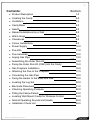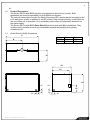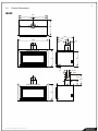
1
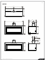
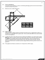
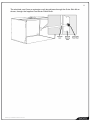
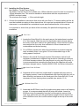
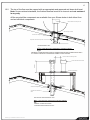
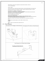
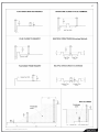
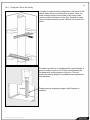
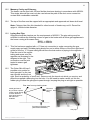
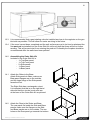
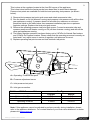
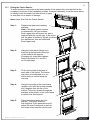
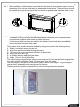
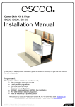
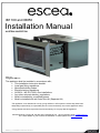
IB1100 and IB850
Installation Manual
AUSTRALIAN EDITION
Important:
The appliance shall be installed in accordance with;
• This installation instruction booklet
• Local gas fitting regulations
• Municipal building codes
• Electrical wiring regulations
• AS 5601 / AG 601-2000, Gas installations
• Any other relevant statutory regulations.
• Must be installed by a qualified person
• Must be installed with an Outer Skin Kit (Separate Kit)
This appliance is not intended for use by young children or infirm persons unless they have been
adequately supervised by a responsible person to ensure that they can use the appliance safely.
Young children should be supervised to ensure that they do not play with the appliance.
Manufactured by: Escea Ltd, PO Box 5277 Dunedin NZ, Ph: +64 3 479 0302, email: [email protected]
For contact details of your local escea distributor or dealer please visit www.escea.net
G8872_8 Installation Manual AU.doc
2
Note:
THERE ARE A FEW THINGS TO CONSIDER BEFORE INSTALLATION
•
Cavity Dimensions, Clearances, and fitting the Outer Skin Kit
•
MUST be installed 100mm minimum off the floor
•
Coupling of flue to fire
•
Coupling of gas lines to fire
•
Fixing the fire to the cavity
•
Supply of electricity to fire
•
Gas pipe placement to the front right of the cavity.
The sequence you choose to do these tasks will vary on your individual scenario.
Please read these instructions fully before proceeding with your installation.
Leave the installation of the fascia panels until the very end of the installation and
commissioning to avoid damage to the fascia panels.
WARNING:
Failure to follow these instructions could cause a malfunction of the
heater, which could result in death, serious bodily injury, and/or property
damage. Failure to follow these instructions may also void your fire
insurance and/or warranty.
Installation:
Installation must be carried out by a registered installer who, on completion of
the installation, must issue a certificate of compliance, in accordance with
national and/or local codes. If a certificate of compliance is not issued then the
Escea warranty may be void.
This appliance needs fresh air for safe operation and must be installed with
provisions for adequate combustion and ventilation air available to the room in
which it is to be operating.
Warranty Repair and Annual Servicing:
Warranty repair work must be carried out by a recognised Escea Gas Fire
Technician. It is recommended that recognised Escea Gas Fire Technicians
are also used to carry out annual servicing requirements (particularly during
the warranty period). For contact details of authorised Escea technicians in
your area, please contact the retailer from whom the appliance was purchased.
The heater must be installed according to these instructions and in compliance
with all relevant building, gas fitting, electrical and other statutory regulations
(eg. AS 5601). Any shortcomings in the appliance and flue installation will be
the responsibility of the installer, and Escea will not be accountable for any
such failings or their consequences.
G8872_8 Installation Manual AU.doc
3
Contents:
Section:
• Product Description
1.0
• Creating the Cavity
2.0
• Ventilation
3.0
• Cavity Base
4.0
• Hearth
5.0
• Raised Installations Up a Wall
6.0
• Wall Linings
7.0
• Clearances
8.0
• Corner Installations
9.0
• Power Supply
10.0
• Flue Kits
11.0
• Flue Assembly
12.0
• Laying Gas Pipe
___ 13.0
• Assembling the Outer Skin Kit
14.0
• Fixing the Outer Skin Kit (OSK) into the Cavity
15.0
• Gas Fireplace Installation
16.0
• Attaching the Flue to the Fireplace
17.0
• Connecting the Gas Pipe
18.0
• Fixing the Heater to the Base and Wall
19.0
• Locating the Log Set
20.0
• Electrode Placement
21.0
• Checking Operating Pressure
22.0
• Fitting the Fascia Panels
23.0
• Locating Wall Mount Cradle for Wireless Control
24.0
• Normal Operating Sounds and Smells
25.0
• Installation Check List
26.0
G8872_8 Installation Manual AU.doc
4
•
1.0
Product Description:
The Escea IB1100 and IB850 gas fires are designed to be built into a cavity. Both
appliances are flued conventionally via a Ø100mm flue system.
The user will control their fire with the Radio Frequency (RF) remote that will normally be left
in its wall mount cradle. In addition to the RF remote it has a single auxiliary on/off button on
the unit. When not in operation it is in a standby mode unless it is physically isolated from
the mains supply.
The Escea IB1100 and IB850 Outer Skin Kit must be used with ALL installations. They
seal the cavity and also prevent any combustible material surrounding from getting
excessively hot.
1.1
Outer Skin Kit (OSK) Dimensions
A
B
IB850
IB1100
A
B
960mm
480mm
1260mm 630mm
345
565
475
560
45
48
190
62
G8872_8 Installation Manual AU.doc
45
5
1.2
Product Dimensions
IB850
960
=
=
565
565
345
1060
270
130
4 SIDED FASCIA
635
560
ø100
ø150
35
Sleeve
travel
400
ø180
3 SIDED FASCIA
600
G8872_8 Installation Manual AU.doc
200
6
IB1100
1260
=
=
565
565
345
1360
270
130
4 SIDED FASCIA
635
560
35
Ø100
Ø150
Sleeve
travel
400
Ø180
3 SIDED FASCIA
600
G8872_8 Installation Manual AU.doc
200
7
2.0
Creating the Cavity:
The dimensioned drawing below shows the size of opening that must be created to fit the
Outer Skin Kit.
Note: It is not necessary to line the side, top or back of the cavity.
Ideal Cavity Dimensions:
All dimensions in millimetres
A
B
C
960
1260
560
560
565
565
B
IB850
IB1100
(Check Offset. Refer 2.2)
A
C
2.1
Where possible, it is recommended that the cavity is made slightly larger than the above
dimensions to give the installer the maximum amount of space to work in.
2.2
The IB1100 and IB850 have their electronics compartment protruding from the left hand side
of the fire and the resulting offset needs to be taken into account when installing into a tight
masonry cavity.
3.0
Ventilation:
It is important to
remember that local
building codes require
additional ventilation be
included into living
spaces where open
flued natural gas
appliances are installed.
Your local building
codes provide formulae
and tables for
calculating the required
ventilation given the size
of the living space and
the gas input of the
appliance.
4.0
Ceiling vent
Be wary of adverse
pressure differences if
venting from ceiling spaces.
Be wary of the effects of
range hood or bathroom
extractor fans etc...
Add “make up air” ventilation to well
sealed living spaces
Wall vent
Cavity Base:
This appliance MUST be fully supported on its base. The base must extend over the entire
area of the underside of the appliance. The base must also be levelled to prevent vibration
from possible fan imbalance. For the installation of an IB1100 the base of the cavity must be
strong enough to support the total product weight, which is a minimum of 70kg
The base of the product must be fully supported at either side and at the centre front to
back.
G8872_8 Installation Manual AU.doc
8
5.0
Hearth:
If this fire is being installed at floor level a hearth made from non-combustible material must
extend no less that 300mm from the front of the fire. This hearth should be at least as wide
as the fire’s outer fascia and no less than 10mm thick. Raised hearths can be any size but
must also be constructed from non combustible materials.
5.1
The floor in front of this hearth will still get warm so if the floor covering is vinyl, nylon carpet
or another heat sensitive material then we recommend extending the hearth to 450mm from
the fire.
5.2
NOTE: If the hearth is to be covered with tiles or some other veneer then the fire must be
installed so that the base of the ‘Outer Skin Kit’ is level with the finished top surface of the
hearth.
6.0
Raising the Fire Up a Wall:
This fire must be installed at a minimum of 100mm off the floor. If the fire is being located in
such a way that the bottom of the cavity is any more than 100mm up off the ground no
hearth is required. Escea recommend that if a heater is being mounted more than 100mm
up a blank wall and no hearth is being used, then a four sided fascia is used (available
from your Escea dealer).
G8872_8 Installation Manual AU.doc
9
7.0
Wall Linings:
The front mounting flanges of the ‘Outer Skin Kit’ MUST be on top of the FINISHED wall
surface in order for the fascia panels to mount properly. Take into account any plaster
board, tiles or any other finishing surface that may be intended for the finished wall surface.
Wall finishing materials must not encroach upon the minimum cavity clearances given in
section 1.0. The wall board that lines the outside of this opening can be normal dry wall
(plaster board) and does not need to be non-combustible.
Note: The temperature of the wall lining directly above the heater does get warm and hence
may discolour paint finishes that are susceptible to temperature damage or distort vinyl wall
coverings. For durability of finishes and surfaces you should contact the relevant
manufacturer for their specification.
150
8.0
8.1
Clearances:
Mantle Clearance
Please refer to the diagram to the right. Mantles or
protruding ledges mounted above the heater that are
made from combustible materials, must not extend
from the wall outside of the dimensions shown.
100
300 200
Television Clearances
The following are the recommended minimum
clearances for the location of any electrical equipment
(such as Plasma TV, LCD TV or home theatre) above
an Escea IB Series gas fire. Use either a shelf or mantle below your
TV screen or alternatively you can construct a recess to mount your
TV screen into.
30
Maintain a 30mm
clearance around the
fascia to ensure ease
of fascia removal.
NB: No clearance is
needed underneath 3
sided fascias
Note: The above television clearance recommendations are to be treated as a suggestion of a suitable installation
only. It is the responsibility of the end user to check the installation instructions of their electrical appliances to ensure
that the location in relation to the gas fire, is suitable. Escea in no way guarantees or takes responsibility that the above
installation suggestion will be suitable for all electrical or home entertainment appliances.
G8872_8 Installation Manual AU.doc
10
9.0
Corner Installations:
If a cavity is to be created in a corner, the following drawings give the minimum sized interior
wall and resultant flue position.
9.1
Minimum corner install dimensions:
A
B
C
D
IB1100
1195
1260
565
600
IB850
1045
960
565
495
10.0
Power Supply:
Whilst the cavity is being created consideration should be given to appropriate location of a
standard 3 pin, EARTHED 240V power outlet. This must be within 0.5m of the rear left hand
corner of the appliance.
10.1
Locating the power outlet within the cavity makes the installation very neat but the provision
MUST be made to be able to switch the power supply off and on (electrical isolation switch)
and MUST be accessible after the heater has been installed. This is normally done by
means of a separate switch located outside of the cavity and wired to the plug. This will
allow service technicians to isolate the power supply before performing service work on the
appliance.
10.2
This appliance will draw a maximum of 1.2 Amps from a 240V supply.
G8872_8 Installation Manual AU.doc
11
The electrical cord (from an extension cord) should pass through the Outer Skin Kit as
shown, through the supplied Cord Strain Relief Bush.
G8872_8 Installation Manual AU.doc
12
11.0
Flue Kits (Glen Dimplex kits only shown. Check with local distributor for availability)
552327 Standard Flue Kit
552332 Offset Flue Kit Black
552333 Offset Flue Kit Galvanised
G8872_8 Installation Manual AU.doc
552330 900mm Flue Extension Kit
Black
552331 900mm Flue Extension Kit
Galvanised
13
12.0
Installing the Flue System:
Non-Masonry Timber Frame Cavity:
The heater must be flued to the outside via a 100mm diameter inner flue that is covered by a
150mm diameter liner. This must be installed in accordance with the requirements of
AS5601 and local codes.
The minimum flue length = 3.6m vertical height
12.1
Consult the installation instructions that come with your flue kit. To ensure safety the flue kit
must be installed according to those instructions. An overview is provided below. Ensure all
clearances to combustibles are maintained as per specifications earlier in this manual.
It is important to check that you have all the necessary flue parts before beginning your
installation.
Gas Cowl
1. Locate the Outer Skin Kit in the cavity as per the instructions in section
15 of this manual. Mark the point for penetration that is directly above
the centre of the flue outlet on the gas fireplace. Check that the location
ensures that the flue outer liner maintains a 25mm clearance to all
combustibles and timber framing.
2. Cut a 200mm square hole where the penetration is required using the
mark created in step 1 as a guide. Fit non-combustible nogs in the
ceiling space if required.
3. Measure the overall flue length required. Remember to allow for all
necessary clearances to neighbouring structures (including a minimum
of 600mm clearance above the nearest point on any part of the roof). It
is recommended that extending the flue above the ridgeline will assist
with down draught issues. Consult AS5601 2002 for further information.
Outer Liner Ø150mm
4. Assemble all the outer liner lengths and fix together with pop rivets or
self tapping screws. Lower the assembled outer liner through the roof (or
false chimney) and secure to the fixed part of the Outer Skin Kit. Fix as
necessary to inner framing where possible (see section 12.4).
Ø100mm Inner Flue
5. Assemble the Ø100mm inner flue lengths using pop rivets or self tapping
screws. It is recommended that all flue joints are sealed. Lower the
Ø100mm inner flue assembly from the roof through the centre of the
outer liner and locate onto the gas fireplace spigot. Ensure that the top
of the Ø100mm inner flue is at the correct height at the top of the outer
liner.
G8872_8 Installation Manual AU.doc
14
6. Fix an appropriate weather shielding to the outer liner at the penetration and seal to the roof
or chimney using an appropriate sealer.
7. Fit the gas cowl.
8. Once gas fireplace is operational check the installation for flue spill where possible
9. Note: It is the installer’s responsibility to ensure the installation complies with AS5601 2002
and all relevant local codes.
G8872_8 Installation Manual AU.doc
15
12.2
The top of the flue must be capped with an appropriate and approved anti down draft cowl.
Note: As per national standards, the finished terminal must be in clear air and not enclosed
in any way.
All the required flue components are available from your Escea dealer in both kitset form
and as individual components.
600mm clearance to nearest part of roof
Seal - Deck Tight or similar
Trimmers shown diagrammatic
25
Gap between flue shield and any timber
Angle fixing bracket
supplied with flue kit.
25
100
150
DESIGN EXAMPLE ONLY
LONG SECTION THROUGH FLUE ENCLOSURE
Scale: NTS
GENERAL CONSTRUCTION AND CLADDING SHOWN AND IS INDICATIVE ONLY
ALL INSTALLATION & FLUING MUST COMPLY WITH AS 5601
200 min but allow for flue flashings at base
200mm min
if another flue shares same enclosure
deck-tite or similar flashing
100
trimmers shown diagrammatic
angle fixing
bracket supplied
with flue kit
150
25
25
gap between flue shield and any
timber
ENCLOSURE DESIGN EXAMPLE ONLY
LONG SECTION THROUGH FLUE ENCLOSURE
Scale: NTS
GENERAL CONSTRUCTION AND
CLADDING SHOWN INDICATIVE ONLY
G8872_8 Installation Manual AU.doc
16
FROM AS5601, please ensure compliance to all other relevant sections of this code.
2.6.13 FLUE TERMINALS
2.6.13.1 Location
The termination point of a flue shall be located in relation to any associated building and to neighbouring
structures so that wind from any direction is not likely to create a downdraught in the flue or chimney.
Except where 2.6.13.3 applies, a flue terminal shall:
(a) Be at least 1m horizontally from a neighbouring structure; or
(b) If less than 1m horizontally from a neighbouring structure, be at least 500mm above that structure;
(c) Be at least 1.5m from any opening into a building; and
(d) Be at least 200mm from another flue terminal.
2.6.13.2 Terminating a flue above a roof
Where a flue is to terminate above:
(a) A roof; the end of the flue shall be at least 500mm from the nearest part of the roof;
(b) A trafficable roof designed for personal or public use, the end of the flue shall be at least 2m above the
roof level and at least 500mm above any surrounding parapet; or
(c) A chimney, the end of the flue shall be at least 200mm from the nearest part of the chimney.
NOTE(1) The distance is measured before the cowl is fitted to the end of the flue
(2) (NA)
(3) (NA)
2.6.13.3 Location of a flue terminal other than above a roof
(NA)
12.3
Flue Clearance:
G8872_8 Installation Manual AU.doc
17
G8872_8 Installation Manual AU.doc
18
12.4
Fixing the Flue to the Cavity
A length of angle should be attached to the inside of the
timber frame cavity to hold the flue in place. Once you
have fixed the angle to the inside of the cavity holes
must be drilled to secure it to the flue. Screws or rivets
can be inserted directly into the 150mm flue to hold it in
place.
To make sure the flue is installed at the correct height, a
piece of timber can be cut to 570mm and between the
fire base level and the bottom of the flue. This will
ensure the correct height for installation and support the
flue assembly.
Timber prop as temporary support until fireplace is
installed.
G8872_8 Installation Manual AU.doc
19
12.5
Masonry Cavity and Chimney:
The heater can be flued with 100mm flexible aluminum ducting in accordance with AS5601.
This single skinned flue must only be used where the path of the duct never comes into
contact with combustible materials.
12.6
The top of the flue must be capped with an appropriate and approved anti down draft cowl.
Note: Chimney liner flue kits intended for other brands of heater may not fit. Escea flue
spigot is 100mm inside diameter.
13.0
Laying Gas Pipe:
Gas pipe should be sized as per the requirements of AS5601. The pipe sizing must be
sufficient to deliver the following volume of gas to the heater with all other gas appliances in
the home running at the same time;
IB850 = 40MJ/hr
IB1100 = 40MJ/hr
13.1
This fire has been supplied with a ½” flare nut connection to make connecting the gas
supply easy and safe. Suitable piping should be run to within 400mm of the front right hand
corner of the fire. ½” Copper tubing should form the last section of piping to the regulator.
Flare the end of the copper
tubing and screw onto the
regulator as illustrated in the
diagram to the right. This
connection must be joint
tested to ensure gas
tightness.
13.2
The Outer Skin Kit has 3
possible entry points for
solid gas pipe, on the two
rear corners and the front
right. Each is sealed by a ‘knock-out’. Remove only the knock-out which you require, and
place the supplied rubber plug into the hole. You will need to make a small cut into the
rubber plug to allow the gas pipe to pass through, keeping the plug as air-tight as possible.
Plan view from top looking down.
Install gas lines to
any of these 3 points.
Leave enough piping
to reach the front
right hand corner of
the OSK once
installed.
Electrical
point of
entry.
Final gas connection point
(after OSK installation)
Gas pipe
G8872_8 Installation Manual AU.doc
20
13.3
It is recommended that a gas isolating valve be installed as close to the regulator on the gas
inlet side as possible. This will allow for easier servicing in the future.
13.4
If the room has not been completed and the wall surfaces are yet to be lined or plastered the
fire must not be installed into the Outer Skin Kit until such time that there will be no further
sanding. This will prevent dust from entering the product. Preferably the fireplace should be
commissioned after the walls have been painted.
14.0
Assembling the Outer Skin Kit:
Included in the Outer Skin Kit is:
- 1x Top-Rear panel
- 1x Top-Front panel
- 2x Side panels
- 1x Rear panel
- 1x Base panel
14.1
Attach the Sides to the Base:
Attach Side panels to Base, make sure
Base panel flanges are on the outside,
and the large flange of the Side panels
faces the front.
The Right Side has a rectangular cutout,
It is important that this is on the right hand
side and that the circular knock-outs are
at the base of the Outer Skin Kit as pictured.
14.2
Attach the Rear to the Sides and Base:
The rear panel fits inside the Side and Base
panels, make sure the flanges on the Side
and Base panels are on the outside. The two
holes on the Rear panel go towards the bottom.
G8872_8 Installation Manual AU.doc
21
14.3
Attach the Top-Rear:
Attach the top-rear panel to the Sides and Rear
panels, with the flanges of the Top-rear panel on
the outside. Do not attach Top-Front panel yet,
this will be done after the flue has been mated
with the fire.
15.0
Fixing the Outer Skin Kit into the Cavity:
Slide the Outer Skin Kit into the cavity, and secure it to the wall using screws or other
fasteners through the slots at the front of the side panels.
The cavity is now ready for the
installation of the Gas Fireplace.
G8872_8 Installation Manual AU.doc
22
16.0
Gas Fireplace Installation:
Attached to the base of the Outer Skin Kit
are guide rails. The inside edge of these
rails will line up with the outside edge of the
two outer under base supports. When the
parts are lined up, push the fire towards the
back of the Outer Skin Kit until it cannot be
pushed back any further. The front of the
firebox should now be sitting flush with the
OSK.
16.1
Removing the Front Glass:
Step 1:
Unscrew the side (where fitted) and top glass retainers and remove them.
Take care that the glass does not fall forwards at this stage
Step 2:
Lift out glass and place it carefully aside.
G8872_8 Installation Manual AU.doc
23
Step 3:
Remove the top of the heater outer shell. Take out the screw from each side
(as shown below), lift and pull the top of heater shell out towards yourself.
Undo screws from both sides
Step 3:
For best access we recommend removing the fire box. Undo the four screws
on the front four corners of the fire box and the two screws on the inside
holding down the fire box (as shown below). Pull the fire box out of the heater.
G8872_8 Installation Manual AU.doc
24
17.0
Attaching the Flue to the Fireplace:
Once the gas fireplace has been inserted
into the OSK and the firebox removed, the
flue can be attached. To do this line up the
100mm flue with the flue outlet spigot and
drop the flue into the spigot.
Note: To increase access through the fire
to reach the flue connection, remove
firebox and lid.
Please consider how the fire will be fixed to the base before installing. Refer to 19.0
for details
18.0
Connecting the Gas Pipe:
When the heater has been pushed back into position the gas pipe can be connected to the
inlet side of the appliance regulator at the front RH corner of the heater. The pipe assembly
should have already been tested as per section 22.0
18.1
The regulator that is supplied with the fire MUST NOT BE REMOVED. Removal of the
regulator, or replacing it with one not intended for use with an Escea fire, will void the limited
appliance warranty.
Note: Refer to 13.2 for further gas pipe laying information as per diagram below
G8872_8 Installation Manual AU.doc
25
Plan view from top looking down.
Install gas lines to
any of these 3 points.
Leave enough piping
to reach the front
right hand corner of
the OSK once
installed.
Electrical
point of
entry.
Final gas connection point
(after OSK installation)
Gas pipe
19.0
Fixing the Heater to the Base and Wall:
There are several ways that the heater can be fixed against movement: It is a requirement
that this heater be securely fastened to the wall and base.
Note: It is important that the outer fascia is used during this process to ensure that the
heater is located in the appropriate position within the cavity.
19.1
Fixing Heater to Base:
The heater has two holes along the front edge of the base panel that have been provided to
allow installers to screw the heater to the floor. Because of a lack of access for drilling it may
be necessary to mark the appropriate location for these screws and then remove the heater
and drill holes through the bottom of the Outer Skin Kit into hard flooring.
Alternatively a socket set can be used to drive in hex headed screws.
G8872_8 Installation Manual AU.doc
26
19.2
Fixing Heater to Wall:
The installer must also fix the heater to the sides of the cavity using the bracket kit provided.
These brackets are attached through the flanges on the side of the Outer Skin Kit. The
flanges of the Outer Skin Kit must be installed over the outer lining surface of the wall i.e.
over the Plaster Board rather than onto a stud which is then subsequently covered with a
wall lining. Otherwise the fire will be sitting too far back and will inhibit the outer Fascia panel
from fitting correctly.
G8872_8 Installation Manual AU.doc
27
20.0
IB850: Locating the Log Set After Replacing the Firebox:
1) Remove packaging from around log sets
2) Place rear log (long rectangular one) into position by inserting it in behind retainer
bracket at rear of fire box.
3) Place front three log sets into position on the log retaining brackets, over the top of the
main burners. The front edge of each log should be located so that its front edge is
directly behind the holes in the top of each burner which should follow the contours of the
logs.
2)
3a)
3b)
3c)
3d)
Align logs to burner holes.
4) c
G8872_8 Installation Manual AU.doc
28
IB850 Log & Template Position
4) Line up some of the coals that have been supplied with this appliance, along the burner
holes in front of the logs.
5) Scatter the remaining coals around to fill the empty spaces left over.
G8872_8 Installation Manual AU.doc
29
20.1
IB1100: Locating the Log Set After Replacing the Firebox:
1) Remove packaging from around log sets
2) Place rear logs (2 x long, rectangular logs) into position by inserting them in behind
retainer brackets.
3) Place front four log sets into position on the log retaining brackets, over the top of the
main burners. The front edge of each log should be located so that its front edge is
directly behind the holes in the top of each burner (with approximately 5mm clearance)
which should follow the contours of the logs.
2)
3)
3a)
3b)
3c)
3d)
Align logs to burner holes
4)
Cover empty spaces around logs on the front burner ONLY with small coals as
provided. It is important that coals are not placed on the rear burner at all.
G8872_8 Installation Manual AU.doc
30
20.2 Log Replacement:
The fire unit should never be used with broken logs. Turn off the fire and allow the unit to cool
before removing the glass to carefully remove the logs. If for any reason a log should need
replacement, you must use the proper replacement log. The position of these logs must be as
shown in the diagrams above.
Note: Improper positioning of logs may create carbon build-up and will alter the unit’s
performance. Malfunctioning due to improper log placement is not covered under
warranty.
21.0
Electrode Placement:
The placement of the electrodes is CRITICAL to the operation of the fire. These are factory
set but if the event that they are moved during installation or the fire is having trouble lighting
or staying lit then below is a guide to electrode placement. Ensure no logs or coals are
touching the electrodes.
22.0
Checking Operating Pressure:
WARNING: The regulator that is supplied with the fire MUST NOT BE REMOVED.
Removal of the regulator, or replacing it with one not intended for use with an Escea fire, will
void the limited appliance warranty.
G8872_8 Installation Manual AU.doc
31
This is done at the regulator located at the front RH corner of the appliance.
This is best done before the fascia panels have been fitted to avoid fascia damage.
Pressure test points are available for both inlet and operating test pressure (as shown
below).
1) Remove inlet pressure test point grub screw and attach manometer tube.
2) Run the heater on full (all burners running) and measure inlet pressure with all the other
gas appliances running. If pressure does not fall within the maximum or minimum
pressures listed on the table below then reassess installation pipe size or upstream
regulator settings. Replace inlet test point grub screw.
3) Remove the operating pressure test point grub screw. Connect manometer tube and
measure pressure with heater running on full (all three burners running) and with all the
other gas appliances running.
4) The heater regulator pressure has been factory set to 0.87kPa for Natural Gas heaters
and 2.30kPa for Propane heaters. Please check that the operating pressure is exactly as
listed and if not, adjust screw in centre of regulator until pressure is correct.
5) Replace operating test point screw and leak test both test points.
B
C
A
D
A = Operating Pressure test point
B = Pressure adjustment screw
C = Inlet pressure test point
D = Inlet gas connection.
IB1100 and IB850 Pressure Table
Minimum Inlet Pressure
Maximum Inlet Pressure
Operating Pressure
Gas Type
Propane
2.5kPa
5.0kPa
2.30kPa
Natural
1.2kPa
5.0kPa
0.87kPa
Note: If this appliance cannot be adjusted to perform correctly during installation, please
refer to the appliance distributor. For contact details of your local escea distributor or dealer
please visit www.escea.net
G8872_8 Installation Manual AU.doc
32
23.0
Fitting the Fascia Panels:
To avoid scratches or knocks to the fascia panels of this heater they must be fitted at the
complete conclusion of the installation process. It may be necessary to use the outer fascia
to initially locate the heater but then remove it again
so that there is no chance of damage.
Note: Never Ever Rub the Fascia Panels.
Step 1:
Replace the glass and retaining
brackets.
Note: If the glass gasket requires
a replacement, call your nearest
Escea agent who will ensure the part is
replaced with the correct type. In the event
that the glass is broken by impact, purchase
the replacement from an authorised
Escea agent only.
Step 2:
Hang the outer fascia (larger one)
from the lip that extends at the top
of the heater at 45 degrees.
If hanging a 4 sided fascia please
Refer to sections 22.1 and 22.2
on the next page.
Step 3:
Fit the two screws at the base of
each side of this fascia. The heater
may have to be adjusted in or out
of the cavity to ensure fascia fits
correctly.
Step 4:
Hang the top edge of the inner fascia
(smaller one) from the lip that extends
at 45 degrees from the top of the
firebox. Fit the two screws through the
brackets at the bottom of the inner fascia
to retain inner fascia panel.
Step 5:
Place the bottom fascia trim into
position. This panel is held on
with magnets. If this panel does not fit,
adjust the outer Fascia side to side or
the heater in/out until the trim fits well.
G8872_8 Installation Manual AU.doc
33
23.1
When installing a 4 sided fascia ensure that the clips that the outer fascia screw into are at
the bottom of the slot on which they are attached as shown below. The outer fascia should
be pushed down onto the top lip so that it is as low as possible and the screw holes in the
fascia line up with the lowered clips.
Top lip
24.0
Locating Wall Mount Cradle for Wireless Control;
The heater’s remote contains the thermostat that will sense the room temperature and
communicate this back to the heater via radio frequency.
A wall mount cradle has been provided for the wireless control and where possible the
control should be housed in this cradle.
The location of this cradle should be decided by taking into account the following factors;
1. Simple, convenient access for the user
2. Away from air flow and drafts through the room
3. The parts of the room that people are likely to spend time
4. Away from direct sun light
5. A suitable distance away from the heater.
6. Ideally 1.2m to 1.5m from the floor
The radio frequency signal will go through some walls but for best results Escea suggest that
the cradle position is between 5 and 15 metres away from the heater.
The best height off the ground to locate the cradle is about chest height. This gives a good
average room temperature and easy access for the user.
Please ensure that cradle is screwed firmly onto wall using the screws provided.
G8872_8 Installation Manual AU.doc
34
25.0
Normal Operating Sounds and Smells;
Note: Each time the fire is lit from cold the glass may fog up with condensation. This is
normal and the condensation will disappear within a few minutes once the glass heats up.
25.1
Sounds
It is possible that you will hear some sounds from your gas appliance. This is perfectly
normal due to the fact that there various types of materials and parts used within your
appliance. Listed below are some examples. These are all normal operating sounds and
should not be considered as defects in your appliance.
Fan:
Escea gas appliances use electric fans to push heated air further into the room. It is not
unusual for the fan to make a “whirring” sound when ON. This sound will increase or
decrease in volume depending on the speed setting of your fan.
Gas Control Valve:
As the gas control valves turn ON and OFF, a dull clicking sound may be audible, this is the
normal operation of a valve. When the fire is switched off after being run for a while, there
may be popping and fluttering noises as the residual gas in the burner burns away. These
are normal and should be no cause for concern.
Unit Body/Firebox:
Different types and thicknesses of steel will expand and contract at different rates resulting
in some “cracking” and “ticking” sounds being heard throughout heating and cool down
processes.
25. 2 Smells:
The first few times the unit is operated, the unit may release an odour and the flames may
appear orange caused by the curing of the paint, the burning off of the starch in the gas logs
and the oils in the metal. This is a temporary curing process which will disappear with use.
A deposit on the inside of the glass, caused by the starch in the logs, may appear as a build
up after several uses. If this film is not removed, it wil bake on and may become difficult to
remove. When the glass is cold, remove it (see section 16.1) and clean the inside with a
non-abrasive cleaner.
DO NOT ATTEMPT TO CLEAN THE GLASS WHILE IT IS HOT. NEVER OPERATE THE UNIT
WITH THE GLASS REMOVED.
G8872_8 Installation Manual AU.doc
35
26.0
Installation Check List:
1
Ensure there is adequate ventilation in the masonry cavity.__
2
Ensure the spark electrodes are correctly positioned.
3
Operating pressure checked with heater running on full (all
burners operating) and all other gas appliances in the house
switched on.
4
Flue Draw checked, 5 minutes after start up.
5
Logs in correct position.
6
Coals spread along front burner.
7
Heater run on high for 60 minutes with house doors and
windows open to clear smell of paint and oils on initial burn._
8
Hearth and mantle clearances comply with these instructions.
9
No combustible materials any closer to heater than these
instructions allow.
Tick here
10 Heater fixed to wall and floor.
11
Leak test all joints and pressure test points. Soapy water drop
test done on pipe work.
________
12 Wall mount cradle screwed to wall.
13 House holder has been shown how to operate heater.
14 Operator manual has been left out for house holder, installer
has filled in their own details and heater serial number into
warranty card.
15 Inform the customer that the fire may continue smelling for a
while after installation depending on frequency & duration of
use
16
Given House Holder Plumbing Industry Commission
Compliance Certificate.______________________________
G8872_8 Installation Manual AU.doc