1
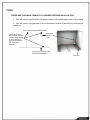
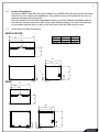
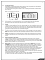
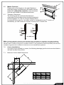
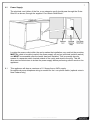
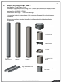
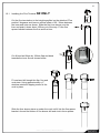
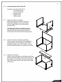
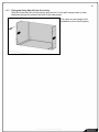
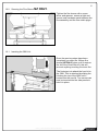
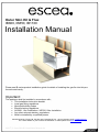
Outer Skin Kit & Flue:
IB600, IB850, IB1100
Installation Manual
Please see IB series product installation guide for details of installing the gas fire into this preformed metal cavity.
Important:
The appliance shall be installed in accordance with;
• This installation instruction booklet
• Local gas fitting regulations
• Municipal building codes
• Electrical wiring regulations
• AS 5601, Gas installations / NZ5261 Gas Installation
• Any other relevant statutory regulations.
• Must be installed by a qualified person
Manufactured by: Escea Ltd, PO Box 5277 Dunedin NZ, Ph: +64 3 479 0302, email: [email protected]
For contact details of your local escea distributor or dealer please visit www.escea.net
630077_5 Outer Skin Kit Installation Manual.doc
2
Note:
THERE ARE TWO MAIN THINGS TO CONSIDER BEFORE INSTALLATION
•
You will need to get 230/240 Volt power supply to the back right corner of the cavity
• You will need to get gas pipe to one of the three corners of the cavity by removing a
knock out
Plan view from top looking down.
Install gas lines to
any of these 3 points.
Leave enough piping
to reach the front
right hand corner of
the OSK once
installed.
Electrical
point of
entry.
Final gas connection point
(after OSK installation)
Gas pipe
630077_5 Outer Skin Kit Installation Manual.doc
3
Contents:
Section:
• Product Description
1.0
• Creating the Cavity
2.0
• Hearth
3.0
• Raised Installations Up a Wall
4.0
• Wall Linings
5.0
• Mantle Clearance
6.0
• Television Clearance
6.1
• Corner Installations
7.0
• Power Supply
8.0
• Installing the Flue System
9.0
• Flue Assembly (NZ ONLY)
10.0
• Flue Assembly (Australia ONLY)
10.2
• Flue Clearance
10.5
• Assembling the Outer Skin Kit
11.0
• Fixing the Outer Skin Kit to the Cavity
12.0
• Laying Gas Pipe
13.0
• Gas Fireplace Installation
14.0
• Attaching the Flue to the Fireplace
15.0
• Securing the Flue Sleeve
16.0
630077_5 Outer Skin Kit Installation Manual.doc
4
1.0
Product Description:
The Escea IB600 Outer Skin Kit (New Zealand only), IB850 Outer Skin Kit and IB1100 Outer
Skin Kit are to be used for all installations. They seal the cavity and isolate the fire from air
pressure changes within the cavity.
The only instance that the OSK might not be fitted is in a New Zealand installation within a
full masonry chimney that is not open to any other building space. If the top of the chimney
is not present and the cavity is open to the roof space then an OSK must be used.
1.1
Outer Skin Kit (OSK) Dimensions:
IB850 & IB1100
A
B
IB850
IB1100
A
B
960mm
480mm
1260mm 630mm
345
565
475
560
45
48
190
62
IB600
45
700
350
345
565
470
585
47
56
48
200
46
630077_5 Outer Skin Kit Installation Manual.doc
5
2.0
Creating the Cavity:
NOTE: When using designer series fascia options the fire cavity dimensions are different.
Check individual fascia instructions for more details.
The dimensioned drawing below shows the size of opening that must be created to fit the
Outer Skin Kit.
Note: It is not necessary to line the cavity.
Ideal Cavity Dimensions:
All dimensions in millimetres
IB Series
IB600
IB850
IB1100
A
700
960
1260
B
585
560
560
C
565
565
565
2.1
Where possible, it is recommended that cavity is made slightly larger than the above
dimensions to give the installer the maximum amount of space to work in.
3.0
Hearth:
If this fire is being installed at floor level a hearth made from non-combustible material must
extend no less that 300mm from the front of the fire. This hearth should be at least as wide
as the fire’s outer fascia and no less than 10mm thick. Raised hearths can be any size but
must also be constructed from non combustible materials.
3.1
The floor in front of this hearth will still get warm so if floor covering is vinyl, nylon carpet or
other heat sensitive material then we recommend extending the hearth to 450mm from the
fire.
3.2
NOTE: If the hearth is to be covered with tiles or some other veneer then the fire must be
installed so that the base of the ‘Outer Skin Kit’ is level with the finished top surface of the
hearth.
4.0
Raised Installations Up a Wall:
If the fire is being located in such a way that the bottom of the cavity is any more than
100mm up off the ground no hearth is required. Escea recommend that if a heater is being
mounted more than 100mm up a blank wall and no hearth is being used, then a four sided
fascia is used (available from your Escea dealer).
5.0
Wall Linings: The front mounting flanges of the ‘Outer Skin Kit’ MUST be on top of the
FINISHED wall surface in order for the fascia panels to mount properly. Take into account
any plaster board, tiles or any other finishing surface that may be intended for the finished
wall surface. Wall finishing materials must not encroach upon the minimum cavity
clearances given in section 1.0. The wall board that lines the outside of this opening can be
normal dry wall (plaster board) and does not need to be non-combustible providing that it
does not come any closer to the fire than the dimensions shown in section 2.0.
Note: The temperature of the wall lining directly above the heater does get warm and hence
may discolour paint finishes that are susceptible
to temperature damage or distort vinyl wall coverings. For durability of finishes and surfaces
you should contact the relevant manufacturer for their specification.
630077_5 Outer Skin Kit Installation Manual.doc
150
6.0
6.1
Mantle Clearance:
Please refer to the diagram to the right. Mantles or
protruding ledges mounted above the heater that are
made from combustible materials, must not extend
from the wall outside of the dimensions shown.
6
100
300 200
Television Clearances:
The following are the recommended minimum
clearances for the location of any electrical equipment
(such as Plasma TV, LCD TV or home theatre) above
an escea IB Series gas fire. Use either a shelf or mantle below your TV screen or
alternatively you can construct a recess to mount your TV screen into.
30
Note: The above television clearance recommendations are to be treated as a suggestion of a suitable installation
only. It is the responsibility of the end user to check the installation instructions of their electrical appliances to ensure
that the location in relation to the gas fire, is suitable. Escea in no way guarantees or takes responsibility that the above
installation suggestion will be suitable for all electrical or home entertainment appliances.
7.0
Corner Installations:
If a cavity is to be created in a corner, the following drawings give the minimum sized interior
wall and resultant flue position.
7.1
Minimum Corner Install Dimensions:
A
B
C
D
IB1100
1195
1260
565
600
630077_5 Outer Skin Kit Installation Manual.doc
IB850
1045
960
565
495
IB600
915
700
565
405
7
8.0
Power Supply:
The electrical cord (either of the fire, or an extension cord) should pass through the ‘Outer
Skin Kit’ as shown, through the supplied ‘Cord Strain Relief Bush’.
Locating the power outlet within the cavity makes the installation very neat but the provision
MUST be made to be able to switch the power supply off and on (electrical isolation switch)
and MUST be accessible after the heater has been installed. This is normally done by
means of a separate switch located outside of the cavity and wired to the plug. This will
allow service technicians to isolate the power supply before performing service work on the
appliance.
8.1
This appliance will draw a maximum of 1.2 Amps from a 240V supply.
No additional power telephone wiring is needed for the i-con phone switch (optional extra in
New Zealand only).
630077_5 Outer Skin Kit Installation Manual.doc
8
9.0
Installing the Flue System NZ ONLY:
Non-Masonry Timber Frame Cavity:
The heater must be flued to the outside via a 100mm diameter stainless steel flue that is
covered by a 150mm diameter liner. This must be installed in accordance with the
requirements of AS5601 / NZ5261.
The minimum flue length = 3.6m vertical height
It is important to check that you have all the necessary flue parts before beginning your
installation.
We recommend that a standard timber flue installation should include the following
components:
1 x Flue Cowl
1 x Flue Liner
Joiner
2 x Flue Liner
Spacer Bracket
3 x Spider
Bracket
3 x 100 x
1200mm Flue
2 x 150 x
1200mm
Galv Flue Liner
1 x 150 x
1040mm
Galv Flue Liner
Angle 50x50x900 Flue
Bracing
630077_5 Outer Skin Kit Installation Manual.doc
1 x 180mm Flue
Sleeve
1 x 100mm Clamping
Flue Sleeve
9
10.0
Flue Assembly NZ
ONLY
Secure the Flue spacer
bracket to the top section of
100mm Flue and insert the
cowl, this can be riveted or
held in place with screws (see
10.1 Installing the Flue
Terminal). Now slide the
150mm flue onto the bracket.
For each section of flue a
Spider bracket will be required.
These act as spacers for the
150mm flue and should be
attached half way along each
section of flue.
The bottom section is similar to
the top assembly. The flue
spacer bracket must be
secured 130mm from the end
of the 100mm flue, this will
give clearance to slide the flue
sleeve up the flue when
installing the Fireplace. Once
the installation is complete the
180mm flue sleeve can be slid
down to cover and protect the
lower assembly.
130mm
630077_5 Outer Skin Kit Installation Manual.doc
10
10.1
Installing the Flue Terminal NZ
ONLY
Cut the flue termination to the height specified on the attached “Flue
position” diagrams and leave a vertical offset of 20 - 30mm between
the inner and outer as shown. Slide the flue liner sleeve over the
liner and push it down about 150mm out of the way. Fit the flue
spacer bracket between the flue and flue liner.
Cut & bend an 80mm by 100mm flap and bend
towards the inner flue as shown below.
Fit cowl and drill trough the flap, flue and
cowl stem. Using approximately a 1"
stainless steel self tapping screw fix the
cowl in place.
Slide the liner sleeve piece up under the cowl until it hits the flue spacer
bracket. Around the bottom of the sleeve drill and rivet in three places.
630077_5 Outer Skin Kit Installation Manual.doc
11
10.2 Flue Kits AUSTRALIA
distributor for availability)
ONLY: (Glen Dimplex kits only shown. Check with local
552327 Standard Flue Kit
552332 Offset Flue Kit Black
552333 Offset Flue Kit Galvanised
630077_5 Outer Skin Kit Installation Manual.doc
552330 900mm Flue Extension Kit
Black
552331 900mm Flue Extension Kit
Galvanised
12
10.3
Installing the Flue System AUSTRALIA ONLY:
Non-Masonry Timber Frame Cavity:
The heater must be flued to the outside via a 100mm diameter inner flue that is covered by a
150mm diameter liner. This must be installed in accordance with the requirements of
AS5601 and local codes.
The minimum flue length = 3.6m vertical height
10.4
AUSTRALIA ONLY Consult the installation instructions that come with your flue
kit. To ensure safety the flue kit must be installed according to those instructions. An
overview is provided below. Ensure all clearances to combustibles are maintained as per
specifications earlier in this manual.
It is important to check that you have all the necessary flue parts before beginning your
installation.
Gas Cowl
1. Locate the Outer Skin Kit in the cavity as per the instructions in section
15 of this manual. Mark the point for penetration that is directly above
the centre of the flue outlet on the gas fireplace. Check that the location
ensures that the flue outer liner maintains a 25mm clearance to all
combustibles and timber framing.
2. Cut a 200mm square hole where the penetration is required using the
mark created in step 1 as a guide. Fit non-combustible nogs in the
ceiling space if required.
3. Measure the overall flue length required. Remember to allow for all
necessary clearances to neighbouring structures (including a minimum
of 600mm clearance above the nearest point on any part of the roof). It
is recommended that extending the flue above the ridgeline will assist
with down draught issues. Consult AS5601 2002 for further information.
Outer Liner Ø150mm
4. Assemble all the outer liner lengths and fix together with pop rivets or
self tapping screws. Lower the assembled outer liner through the roof (or
false chimney) and secure to the fixed part of the Outer Skin Kit. Fix as
necessary to inner framing where possible (see section 12.4).
Ø100mm Inner Flue
5. Assemble the Ø100mm inner flue lengths using pop rivets or self tapping
screws. It is recommended that all flue joints are sealed. Lower the
Ø100mm inner flue assembly from the roof through the centre of the
outer liner and locate onto the gas fireplace spigot. Ensure that the top
of the Ø100mm inner flue is at the correct height at the top of the outer
liner.
630077_5 Outer Skin Kit Installation Manual.doc
13
6. Fix an appropriate weather shielding to the outer liner at the penetration and seal to the
roof or chimney using an appropriate sealer.
7. Fit the gas cowl.
8. Once gas fireplace is operational check the installation for flue spill where possible
9. Note: It is the installer’s responsibility to ensure the installation complies with AS5601 2002
and all relevant local codes.
630077_5 Outer Skin Kit Installation Manual.doc
14
The top of the flue must be capped with an appropriate and approved anti down draft
cowl.
All the required flue components are available from your escea dealer in both kitset form and
as individual components.
500m
m
cleara
nce to
neare
st
part o
f roof
Seal - Deck Tight or similar
Trimmers shown diagrammatic
Gap between flue shield and any timber
25
25
Angle fixing bracket
supplied with flue kit.
100
150
DESIGN EXAMPLE ONLY
LONG SECTION THROUGH FLUE ENCLOSURE
Scale: 1:10
GENERAL CONSTRUCTION AND CLADDING SHOWN AND IS INDICATIVE ONLY
200 min but allow for flue flashings at base
If another flue shares
same enclosure
200mm min
10.5
Deck-tite or similar flashing
100
Trimmers shown diagrammatic.
Gap between flue shield and any timber.
Angle fixing bracket
supplied with flue kit.
150
25
25
ENCLOSURE DESIGN EXAMPLE ONLY
LONG SECTION THROUGH FLUE ENCLOSURE
Scale: 1:10
GENERAL CONSTRUCTION AND CLADDING SHOWN INDICATIVE ONLY
630077_5 Outer Skin Kit Installation Manual.doc
15
FROM AS5601, please ensure compliance to all other relevant sections of this code.
2.6.13 FLUE TERMINALS
2.6.13.1 Location
The termination point of a flue shall be located in relation to any associated building and to
neighboring
structures so that wind from any direction is not likely to create a downdraught in the flue or
chimney.
Except where 2.6.13.3 applies, a flue terminal shall:
(a) Be at least 1m horizontally from a neighboring structure; or
(b) If less than 1m horizontally from a neighboring structure, be at least 500mm above that
structure;
(c) Be at least 1.5m from any opening into a building; and
(d) Be at least 200mm from another flue terminal.
2.6.13.2 Terminating a flue above a roof
Where a flue is to terminate above:
(a) A roof; the end of the flue shall be at least 500mm from the nearest part of the roof;
(b) A trafficable roof designed for personal or public use, the end of the flue shall be at least
2m above the roof level and at least 500mm above any surrounding parapet; or
(c) A chimney, the end of the flue shall be at least 200mm from the nearest part of the
chimney.
NOTE(1) The distance is measured before the cowl is fitted to the end of the flue
(2) (NA)
(3) (NA)
2.6.13.3 Location of a flue terminal other than above a roof
(NA)
630077_5 Outer Skin Kit Installation Manual.doc
16
10.6
Flue Clearance:
630077_5 Outer Skin Kit Installation Manual.doc
17
630077_5 Outer Skin Kit Installation Manual.doc
18
10.7
Fixing the Flue to the Cavity
A length of angle should be attached to the inside of the
timber frame cavity to hold the flue in place. Once you
have fixed the angle to the inside of the cavity holes
must be drilled to secure it to the flue. Screws or rivets
can be inserted directly into the 150mm flue to hold it in
place.
To make sure the flue is installed at the correct height, a
piece of timber can be cut to 600mm and between the
fire base level and the bottom of the flue. This will
ensure the correct height for installation and support the
flue assembly.
Timber prop. as temporary support until fireplace is
installed.
630077_5 Outer Skin Kit Installation Manual.doc
19
11.0
Assembling the Outer Skin Kit:
Included in the Outer Skin Kit is:
- 1x Top-Rear panel
- 1x Top-Front panel
- 2x Side panels
- 1x Rear panel
- 1x Base panel
11.1
Attach the Sides to the Base:
Attach Side panels to Base, make sure
Base panel flanges are on the outside,
and the large flange of the Side panels
faces the front.
The Right Side has a rectangular cutout,
It is important that this is on the right hand
Side and that the circular knock-outs are
At the base of the Outer Skin Kit as pictured.
11.2
Attach the Rear to the Sides and Base:
The rear panel fits inside the Side and Base
panels, make sure the flanges on the Side
and Base panels are on the outside. The two
holes on the Rear panel go towards the bottom.
11.3
Attach the Top-Rear:
Attach the top-rear panel to the Sides and Rear
panels, with the flanges of the Top-rear panel on
the outside. Do not attach Top-Front panel yet,
This will be done after the flue has been mated
with the fire.
630077_5 Outer Skin Kit Installation Manual.doc
20
12.0
Fixing the Outer Skin Kit into the Cavity:
Slide the Outer Skin Kit into the cavity, and secure it to the wall using screws or other
fasteners through the slots at the front of the side panels.
The cavity is now ready for the
installation of the Gas Fireplace.
630077_5 Outer Skin Kit Installation Manual.doc
21
13.0
Laying Gas Pipe:
Gas pipe should be sized as per the requirements of AS5601 / NZ5261:2003. The pipe
sizing must be sufficient to deliver the following volume of gas to the heater with all other
gas appliances in the home running at the same time;
IB600
IB850
IB1100
New Zealand
36 MJ/hr
42 MJ/hr
42 MJ/hr
Australia
----40 MJ/hr
40 MJ/hr
13.1
This fire has been supplied with a 300mm long flexible inlet connection to make connecting
the gas supply easy and safe. Solid pipe should be run to within 100mm of the front right
hand corner of the fire and connected to the end of the supplied flexible hose via a 15mm
flared union (supplied with the Gas Fire).
13.2
The Outer Skin Kit has 3 possible entry points for solid gas pipe, on the two rear corners and
the front right. Each is sealed by a ‘knock-out’. Remove only the knock-out which you
require, and place the supplied rubber plug into the hole. You will need to make a small cut
into the rubber plug to allow the gas pipe to pass through, keeping the plug as air-tight as
possible.
13.3
This flexible pipe should be attached to the copper supply pipe and the joint tested to ensure
gas tightness. The end of the flexible connection pipe has a flare fitting and nut to suit ½
inch (12.7mm) copper pipe.
13.4
If the room has not been completed and the wall surfaces are yet to be lined or plastered the
fire must not be installed into the Outer Skin Kit until such time that there will be no further
sanding. This will prevent dust from entering the product. Preferably the Fireplace should be
commissioned after the walls have been painted.
630077_5 Outer Skin Kit Installation Manual.doc
22
14.0
Gas Fireplace Installation:
Attached to the base of the Outer Skin Kit
are guide rails. The inside edge of these
rails will line up with the outside edge of
the two outer under base supports. When
the parts are lined up, push the fire
towards the back of the Outer Skin Kit until
it cannot be pushed back any further. The
front of the firebox should now be sitting
flush with the OSK.
15.0
Attaching the Flue to the Fireplace NZ
ONLY:
Once the Gas fireplace has been inserted
into the OSK, the flue can be attached. To
do this line up the 100mm flue with the flue
outlet spigot then slide the clamping flue
sleeve down onto the spigot. (NZ ONLY)
Note: To increase access through the fire
to reach the flue connection, remove
firebox and lid.
630077_5 Outer Skin Kit Installation Manual.doc
23
16.0
Securing the Flue Sleeve NZ
ONLY:
Tighten the flue sleeve with a screw
driver and spanner, ensure a tight and
secure seal has been made between the
flue assembly and the flue outlet spigot.
16.1
Inserting the OSK Lid:
Once the previous steps have been
completed you slide the 180mm flue
sleeve (NZ ONLY) down until it rests on
the lid of the Outer Skin Kit, this will
prevent anything touching the inner flue.
The final step is to attach the front lid to
the OSK. This is attached by sliding the
lid along the top of the OSK until it
locates into the rear lid. Two screws can
now be inserted into the side panels to
hold it in place.
630077_5 Outer Skin Kit Installation Manual.doc