1
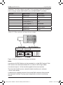
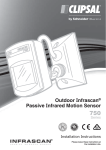
DALI Gateway
5502DAL
Programming Guide
REGIST
23446_F2255-01 5502DAL C-Bus DALI Gateway APPROVED.indd 1
30/08/2011 10:38:16 AM
5502DAL C-Bus DALI Gateway
Programming Guide
Contents
1.0
Introduction .............................................................................................................3
1.1 Description .........................................................................................................3
1.2 Definitions...........................................................................................................4
2.0
Concepts ..................................................................................................................5
2.1 C-Bus..................................................................................................................5
2.2 DALI....................................................................................................................6
2.3 C-Bus to DALI Address Mapping ......................................................................7
3.0
Wiring Notes ............................................................................................................7
4.0
Messages .................................................................................................................9
5.0
Setup.........................................................................................................................9
5.1 DALI Setup .........................................................................................................9
5.2 C-Bus Setup .....................................................................................................10
6.0
Scenes ....................................................................................................................10
7.0
Specifications ........................................................................................................11
8.0
Standards Complied .............................................................................................12
9.0
Two Year Warranty .................................................................................................13
© 2011 Schneider Electric. All Rights Reserved.
23446_F2255-01 5502DAL C-Bus DALI Gateway APPROVED.indd 2
30/08/2011 10:38:16 AM
5502DAL C-Bus DALI Gateway
Programming Guide
1.0 Introduction
This Programming Guide provides basic set-up information for the C-Bus DALI
Gateway. For additional information refer to C-Bus Toolkit software Help. Installers
should contact the supplier of the Digital Addressable Lighting Interface (DALI)
equipment to obtain the programming and commissioning software for DALI
devices.
1.1 Description
The DIN rail mounted unit is normally installed inside an enclosure. The unit takes
up 4M of space on a DIN rail. The C-Bus DALI Gateway uses RJ45 sockets for
C-Bus connectivity. The unit has two C-Bus status indicator LEDs labelled Unit
Comms and C-Bus.
Catalogue Number
Description
5502DAL
C-Bus-to-DALI Gateway, DIN rail
mounted, provides communication
between one C-Bus network and two
DALI networks
Table 1. Product catalogue number and description
The DALI Gateway draws 32mA from the connected C-Bus network. The unit does
not provide power to either the C-Bus network or the DALI networks. The gateway
does not require mains power to operate.
The DALI specification is a communications protocol for controllers and electronic
lamp ballasts. The DALI specification, developed by ballast manufacturers, includes
a description of the electrical characteristics of the signal, and defines a protocol for
the messages that will pass between controllers and ballast units.
The 5502DAL C-Bus-to-DALI Gateway provides an interface between a C-Bus
network and up to two DALI networks and enables the two network types to interact
with each other. The older gateway units were pre-programmed with a C-Bus
to DALI and DALI to C-Bus addressing structure. The current model 5502DAL
Gateway is programmed using Toolkit software that is downloaded free from the
Clipsal CIS website.
Using C-Bus, the DALI gateway controls and monitors DALI compatible ballasts
and ELV transformers (from various ballast manufacturers) over the C-Bus network.
DALI power supplies are not provided with the DALI Gateway.
© 2011 Schneider Electric. All Rights Reserved.
23446_F2255-01 5502DAL C-Bus DALI Gateway APPROVED.indd 3
3 of 16
30/08/2011 10:38:16 AM
5502DAL C-Bus DALI Gateway
Programming Guide
1.2 Definitions
The following definitions are useful in discussing the DALI Gateway:
Term
Definition
C-Bus Load
Any device connected to an electric circuit
that consumes power controlled by a C-Bus
Output Unit (examples are lights and electric
motors).
C-Bus Output Unit
A device, such as a relay or dimmer, that
directly controls electric loads.
C-Bus Input Unit
A device used to control loads (examples
are key switches and passive infrared motion
detectors).
Fade Rate
The time taken for a load to reach a certain
level. Fade rate generally refers to light
dimming.
Zones
Areas within a floor space may be divided up
into zones.
Scene
A combination of loads to be controlled.
Scenes may be relevant to zones and
incorporate fade rates.
Application Address
C-Bus may be used for different uses or
applications. Application addressing is a
method to allow this.
Unit Address
Every C-Bus unit has a unique identity called
a unit address. Each unit has an individual
address so that the unit can be specified for
various actions.
Short Address
An address used in DALI systems. Used in a
manner similar to C-Bus Unit Addresses.
Group Address
Group addresses are identifiers that are
programmed into C-Bus units to create
associations between C-Bus input units
and C-Bus output units, to control loads
connected to the output units.
Table 2. Terms and definitions
Note: This document makes use of hexadecimal numbers that are prefixed by a
dollar sign and followed by the decimal equivalent. For example, if we refer to the
Hexadecimal Group Address 42, this is the same as decimal Group Address 66,
and is written as $42 (66).
4 of 16
23446_F2255-01 5502DAL C-Bus DALI Gateway APPROVED.indd 4
© 2011 Schneider Electric. All Rights Reserved.
30/08/2011 10:38:17 AM
5502DAL C-Bus DALI Gateway
Programming Guide
2.0 Concepts
The C-Bus and DALI systems share many similar concepts. This similarity provides
a basis for interconnecting the two systems. Before exploring the mapping between
the two systems, it is worth summarising the basic concepts in the two systems.
2.1 C-Bus
C-Bus is a microprocessor-controlled network system that uses Unshielded Twisted
Pair cable (UTP, Category 5e). The system is highly flexible in the way it operates
because each device communicating on C-Bus has its own inbuilt microprocessor.
These devices are field programmed with Toolkit software to provide optimum
performance in any installation.
Control messages come from input units such as key units, light level and passive
infrared occupancy sensors. Messages are sent over the C-Bus network to output
units such as relays and dimmers. These messages are used to control the loads
connected to the output units.
Unit Addresses
All units on the C-Bus network have a unique identity code called a unit address.
This code forms part of the messages sent to C-Bus, so that only one unit
corresponding to that address responds. These messages are typically used to
activate the operating variables of the C-Bus devices.
The unique unit address means that:
• AseachC-Busunithasitsownmicroprocessorwithnon-volatilememory
(EEPROM), it is possible through the unique unit address to individually
program each unit.
• TheuniqueunitaddressisthenusedbyC-Bustopasscommandsoverthe
network to specific units with instructions on what to do.
In this way you can program individual units without removing them from the
C-Bus network.
Application Addresses
An application address can identify devices on the C-Bus network. Units can be
grouped together so that commands issued to that group will not affect other groups.
For example, commands to execute scenes on the trigger control application will
not affect a load on the lighting application. This grouping separates all lighting units
from other types of units and commands.
© 2011 Schneider Electric. All Rights Reserved.
23446_F2255-01 5502DAL C-Bus DALI Gateway APPROVED.indd 5
5 of 16
30/08/2011 10:38:17 AM
5502DAL C-Bus DALI Gateway
Programming Guide
Group Addresses
Within the lighting applications, group addresses are used to emulate the function
of conventional wiring. The C-Bus addressing scheme allows you to have up to 255
groups. Each group is like a lighting circuit and can be controlled separately from
any other group.
A group association is programmed into both input units (key inputs and sensors)
and output units (relays and dimmers). Any message broadcast by the input units
for that group are read by the output units that share the same group address.
Loads are switched or dimmed as appropriate.
2.2 DALI
The DALI system uses both short addresses (analogous to unit addresses)
and group addresses (very similar to the C-Bus concept) to achieve a flexible
assignment of loads to inputs.
The main differences between DALI and C-Bus are in the actual implementation of
group addresses and the nature of the commands broadcast over the DALI network.
DALI Group Addresses
The DALI units may have up to 16 group addresses each. This means that if
a unit has groups numbered 1,2,3 and 4 associated with it then it will respond
to a message addressed to group 1,2,3 or 4. Note that in a C-Bus system by
comparison, a load can only have one group address.
DALI Lighting Commands
The DALI system supports many commands that turn a load on or off, ramp it or
perform other functions. The controlled lighting ballast has a level and fade rate
programmed into it. The level and fade rate apply to any ramp command received by
the ballast, until such time as the parameters are changed by the DALI configuration
software.
The level is not stored internally in the ballast, but the fade rate and fade time are.
Also stored in the ballast are parameters like power on level and mode level. The
current level is not stored, but is sent from C-Bus with each command.
There are two fade settings. The fade ‘rate’ and fade ‘time.’ The 5502DAL Gateway
uses the fade time setting.
In a C-Bus system each ramp command contains instructions for the level and fade
rate. A specified dimming ballast can generate the requested fade rate or level and
repeat the operation in rapid succession, each time at a different fade rate and level.
6 of 16
23446_F2255-01 5502DAL C-Bus DALI Gateway APPROVED.indd 6
© 2011 Schneider Electric. All Rights Reserved.
30/08/2011 10:38:17 AM
5502DAL C-Bus DALI Gateway
Programming Guide
2.3 C-Bus to DALI Address Mapping
A user-configurable table in the Toolkit GUI maps the addresses used by C-Bus
and those by the DALI system. Refer to Toolkit Help for assistance in mapping
C-Bus to DALI.
3.0 Wiring Notes
CAUTION
Do not tie the outputs of the DALI power supplies together.
Damage to the supplies and the Gateway unit will occur.
Do not connect the DALI Gateway to mains power. The unit is powered from the
C-Bus network. The Gateway unit does not supply power to the C-Bus network or to
the DALI networks.
Figure 1. Wiring diagram
© 2011 Schneider Electric. All Rights Reserved.
23446_F2255-01 5502DAL C-Bus DALI Gateway APPROVED.indd 7
7 of 16
30/08/2011 10:38:17 AM
5502DAL C-Bus DALI Gateway
Programming Guide
Two RJ45 connectors are provided for upstream and downstream network
attachment. The C-Bus network uses pink Cat 5e, polarised 15-36 volt, twisted-pair
cable, catalogue number 5005C305B (solid) and 5005C305BST (stranded).
RJ45 pin
Signal name
Wire Colour
1
Remote ON
green & white
2
Remote ON
green
3
C-Bus negative ( – )
orange & white
4
C-Bus positive ( + )
blue
5
C-Bus negative ( – )
blue & white
6
C-Bus positive ( + )
orange
7
Remote OFF
brown & white
8
Remote OFF
brown
Table 3. C-Bus network wiring colours codes
Figure 2. RJ45 pin assignments for plugs and sockets
Notes:
A maximum of 64 DALI devices can be connected on a single DALI network. Each
DALI network must be interconnected with a maximum total wiring of 300m.
A maximum torque of 1.4 Nm should be applied to the screw terminals.
The wire used should be mains rated with double insulation and a minimum
1.5 mm² cross section.
A rubber plug is supplied to close off the unused RJ45 connector. Always ensure
that the plug is installed. The plug stops foreign bodies and dust from entering
the unit.
8 of 16
23446_F2255-01 5502DAL C-Bus DALI Gateway APPROVED.indd 8
© 2011 Schneider Electric. All Rights Reserved.
30/08/2011 10:38:17 AM
5502DAL C-Bus DALI Gateway
Programming Guide
4.0 Messages
When a C-Bus command is sent on the C-Bus network to turn off a mapped group
address this message will be transmitted by the DALI Gateway to the appropriate
load on the DALI network. The converse is also true; a message on the DALI
network can be translated and transmitted on the C-Bus network.
For example, if a key input unit is programmed to toggle Group Address $42 (66),
then DALI_1_GROUP2 will respond. Similarly, if something on the DALI network
were to command DALI_1_GROUP2 to change, then a message to do the same
thing appears on the C-Bus network for Group Address $42 (66). So, an Off
command on the DALI 1 Network to Group 2 makes the indicator on the key input
unit turn off. Pressing the key input unit sends an On command back to the DALI
network to Group 2.
Note: The values transmitted from the DALI Gateway are not stored anywhere in
the C-Bus Network unless a C-Bus unit is programmed to that Group Address.
5.0 Setup
The hybrid systems relevant to the DALI Gateway product necessarily involve both
DALI and C-Bus programming. The following sections touch upon the requirements.
5.1 DALI Setup
Initially, the DALI system will not contain any groups until they are programmed into
the DALI units. DALI programming and commissioning software is sourced from the
manufacturer of the ballasts being used.
The default behaviour of DALI units is to respond to Broadcast On and Broadcast
Off commands. The DALI network is split into two halves: DALI 1 Network and DALI
2 Network.
The Group Addresses $60 (96) and $61 (97) correspond to DALI_1_BROADCAST
and DALI_1_OFF. These addresses turn all the loads in DALI network A On and Off,
respectively. Similarly the Group Addresses $E0 (224) and $E1 (225) correspond to
DALI_2_BROADCAST and DALI_2_OFF.
To obtain finer control of the network, individual group addresses have to be applied
to the DALI units. Although each DALI unit can contain up to 16 DALI groups, the
simplest programming option is to provide only one group per unit.
This will provide 16 distinct lighting zones. For large commercial spaces this should
be adequate.
© 2011 Schneider Electric. All Rights Reserved.
23446_F2255-01 5502DAL C-Bus DALI Gateway APPROVED.indd 9
9 of 16
30/08/2011 10:38:17 AM
5502DAL C-Bus DALI Gateway
Programming Guide
5.2 C-Bus Setup
Program the C-Bus DALI Gateway using C-Bus Toolkit software that can be
downloaded free of charge from the Internet.
To determine the C-Bus group addresses, refer to the DALI programming table.
Since these are effectively fixed, we suggest that the DALI Gateway and any key
input units associated with DALI be placed on another lighting application, such
as $39 (57) to avoid unforseen interactions between DALI and any existing C-Bus
lighting project.
6.0 Scenes
The DALI system provides for scenes by pre-programming each unit to be ‘aware’
of which scenes it participates in and setting a specified arc level for that scene.
Sending the DALI_1_SCENE12, for example, will notify all units in that scene to
carry out their programmed action.
The DALI scenes are quite independent of the groups and the units do not betray
their membership in a scene in any remotely assessable way. The DALI scene
message does not describe which units are involved, so ‘listening in’ on the DALI
network traffic would not provide information about which loads are involved.
A C-Bus scene, on the other hand, includes both the scene triggering message
(on the trigger control application) and the subsequent lighting messages (on the
lighting application), so the relevant parts of the state of the system can be inferred
from the messages.
In addition to this, C-Bus scenes can be actioned by numerous devices, such as
Scene Master, Neo, Reflections, C-Touch, and software such as C-Gate. Any C-Bus
input device anywhere on the network can trigger these devices and software.
In general, we recommend that scenes be implemented using C-Bus: the DALI
network will participate in any scenes generated by C-Bus via the DALI Gateway.
All monitoring software will be appraised of scene progress through the usual C-Bus
techniques. Individual DALI keys can still be used provided they are programmed
to address groups only. Any application address from $30 (48) to $5F (95) is a valid
lighting address.
As mentioned above, scenes can be implemented using DALI, but unfortunately any
monitoring package is ‘blind’ to what is going on over the network.
10 of 16
23446_F2255-01 5502DAL C-Bus DALI Gateway APPROVED.indd 10
© 2011 Schneider Electric. All Rights Reserved.
30/08/2011 10:38:17 AM
5502DAL C-Bus DALI Gateway
Programming Guide
7.0 Specifications
Parameter
Value
C-Bus input voltage
15-36V d.c.
Current drawn
32mA from the C-Bus network. The
gateway does not provide power to the
network.
C-Bus AC input impedance
50kΩ at 1kHz
Electrical isolation
3.75kV RMS for one minute between
C-Bus and the DALI networks
Maximum number of units on a single
C-Bus network
50 units
Connections
C-Bus: 2 – RJ45 connectors
DALI: 2 screw terminals per DALI
network
Mounting type
DIN rail
Max.number of DALI addressable units
64 per DALI network
System clock and burden
Software selectable
Operating temperature
0° to 45°C
Humidity
10 to 95%, non-condensing
Weight
130 grams
The DALI power supplies are not provided with the DALI Gateway.
© 2011 Schneider Electric. All Rights Reserved.
23446_F2255-01 5502DAL C-Bus DALI Gateway APPROVED.indd 11
11 of 16
30/08/2011 10:38:17 AM
5502DAL C-Bus DALI Gateway
Programming Guide
8.0 Standards Complied
The 5502DAL C-Bus DALI Gateway meets the following standards.
Australian/New Zealand EMC & Electrical Safety Frameworks and Standards
Regulation
Standard
Title
EMC
AS/NZS CISPR 22
Information technology
equipment - Radio disturbance
characteristics (EMC)
Safety
AS/NZS 61347-2-11 Particular requirements Miscellaneous electronic circuits
used with luminaires
European Directives and Standards
European
Council
Directive
Standard
Title
EMC
Directive
2004/108/EC
EN 55022
Information technology equipment Radio disturbance characteristics
EN 55024
Information technology equipment Immunity characteristics
Safety
EN 61347-2-11
Particular requirements Miscellaneous electronic circuits
used with luminaires
Low Voltage
Directive
2006/95/EC
Lighting equipment - Electrical,
mechanical, chemical and all other
risks
RoHS
2002/95/EC
Reduction of hazardous substances
Other International Directives and Standards
Regulation
Standard
Title
EMC
CISPR 22
Information technology
equipment - Radio disturbance
characteristics
Immunity
CISPR 24
Information technology equipment
- Immunity characteristics
Safety
IEC 61347-2-11
Particular requirements Miscellaneous electronic circuits
used with luminaires
12 of 16
23446_F2255-01 5502DAL C-Bus DALI Gateway APPROVED.indd 12
© 2011 Schneider Electric. All Rights Reserved.
30/08/2011 10:38:17 AM
5502DAL C-Bus DALI Gateway
Programming Guide
9.0 Two Year Warranty
The 5502DAL C-Bus DALI Gateway carries a two year warranty against
manufacturing defects.
Warranty Statement
The benefits conferred herein are in addition to, and in no way shall be deemed to
derogate, either expressly or by implication, any or all other rights and remedies in
respect to the Schneider Electric product, which the consumer has in the location
where the product is sold.
The warrantor is Schneider Electric with offices worldwide.
This Schneider Electric product is guaranteed against faulty workmanship and
materials for a period of two (2) years from the date of installation.
Schneider Electric reserves the right, at its discretion, to either repair free of parts
and labour charges, replace or offer refund in respect to any article found to be
faulty due to materials, parts or workmanship.
This warranty is expressly subject to the Schneider Electric product being installed,
wired, tested, operated and used in accordance with the manufacturer’s instructions.
Any alterations or modifications made to the product without permission of
Schneider Electric might void the warranty.
Schneider Electric shall meet all costs of a claim. However, should the product that
is the subject of the claim be found to be in good working order, all such costs shall
be met by the claimant.
When making a claim, the consumer shall forward the Schneider Electric product to
the nearest Clipsal by Schneider Electric office. Provide adequate particulars of the
defect within 28 days of the fault occurring. The product should be returned securely
packed, complete with details of the date and place of purchase, description of load,
and circumstances of malfunction.
For all warranty enquiries, contact your local Clipsal or Schneider Electric sales
representative.
The address and contact number of your nearest sales office can be found at
http://www.clipsal.com/locations or by telephoning Technical Support 1300 722 247
(CIS Technical Support Hotline, Australia).
© 2011 Schneider Electric. All Rights Reserved.
23446_F2255-01 5502DAL C-Bus DALI Gateway APPROVED.indd 13
13 of 16
30/08/2011 10:38:17 AM
5502DAL C-Bus DALI Gateway
Programming Guide
Notes
14 of 16
23446_F2255-01 5502DAL C-Bus DALI Gateway APPROVED.indd 14
© 2011 Schneider Electric. All Rights Reserved.
30/08/2011 10:38:17 AM
5502DAL C-Bus DALI Gateway
© 2011 Schneider Electric. All Rights Reserved.
23446_F2255-01 5502DAL C-Bus DALI Gateway APPROVED.indd 15
Programming Guide
15 of 16
30/08/2011 10:38:17 AM
Technical Support
For further assistance in using this product, consult your nearest Clipsal Integrated
Systems (CIS) Sales Representative or Technical Support Officer.
Technical Support Contact Numbers
Australia
1300 722 247 (CIS Technical Support Hotline)
New Zealand
0800 888 219 (CIS Technical Support Hotline)
Northern Asia
+852 2484 4157 (Clipsal Hong Kong)
South Africa
011 314 5200 (C-Bus Technical Support)
Southern Asia
+603 7665 3555 Ext. 236 or 242 (CIS Malaysia)
United Kingdom
0870 608 8 608 (Schneider Electric Support)
Schneider Electric (Australia) Pty Ltd
Contact us: clipsal.com/feedback
National Customer Care Enquiries:
Tel 1300 2025 25
Fax 1300 2025 56
Schneider Electric (Australia) Pty Ltd reserves the right to
change specifications, modify designs and discontinue items
without incurring obligation and whilst every effort is made to
ensure that descriptions, specifications and other information
in this catalogue are correct, no warranty is given in respect
thereof and the company shall not be liable for any error therein.
© 2011 Schneider Electric. All Rights Reserved.
Trademarks are owned by Schneider Electric Industries SAS or
its affiliated companies.
F2255/01
23446_F2255-01 5502DAL C-Bus DALI Gateway APPROVED.indd 16
CLIPCOM 23446 August 2011
30/08/2011 10:38:17 AM