1
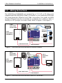
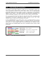
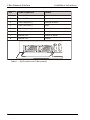
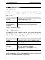
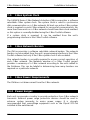
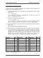
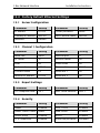
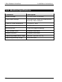
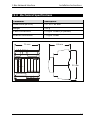
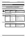
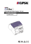
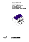
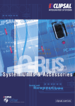
C-Bus Network Interface
Installation Instructions
5500CN Series
© Copyright Clipsal Australia Pty Ltd 2008. All rights reserved. This material is
copyright under Australian and international laws. Except as permitted under the
relevant law, no part of this work may be reproduced by any process without
prior written permission of and acknowledgement to Clipsal Australia Pty Ltd.
Clipsal, C-Bus and Schedule Plus are registered trademarks and HomeGate is a
trademark of Clipsal Australia Pty Ltd.
Lantronix is a registered trademark and DeviceInstaller is a trademark of
Lantronix Corporation California.
Java is a registered trademark of Sun Microsystems, Inc.
Windows is a registered trademark of Microsoft Corporation.
The information in this manual is provided in good faith. Whilst Clipsal Australia
Pty Ltd (CAPL) has endeavoured to ensure the relevance and accuracy of the
information, it assumes no responsibility for any loss incurred as a result of its
use. CAPL does not warrant that the information is fit for any particular purpose,
nor does it endorse its use in applications that are critical to the health or life of
any human being. CAPL reserves the right to update the information at any time
without notice.
V2.0 Nov 2006/ Aug 2008
Contents
1.0
Product Range
5
2.0
Important Notes
5
3.0
4.0
Description
Wiring Instructions
5
6
5.0
C-Bus Network Connection
7
6.0
Status Indicators
9
6.1
Ethernet
9
6.2
C-Bus/Unit/Comms
9
7.0
C-Bus System Clock
10
8.0
C-Bus Network Burden
10
9.0
C-Bus Power Requirements
10
10.0
Power Surges
10
11.0
Megger Testing
11
12.0
Configuration
11
13.0
12.1
C-Bus Programming
11
12.2
Ethernet Setup
11
Factory Default Ethernet Settings
15
13.1
Server Configuration
15
13.2
Channel 1 Configuration
15
13.3
Expert Settings
15
13.4
Security
15
14.0
Electrical Specifications
16
15.0
Mechanical Specifications
17
16.0
Standards Complied
18
17.0
Warranty
19
C-Bus Network Interface
4
Installation Instructions
C-Bus Network Interface
1.0
Installation Instructions
Product Range
5500CN
C-Bus Network Interface (with 12 V DC, 500 mA AU plug pack)
E5500CN C-Bus Network Interface (no plug pack included)
2.0
•
•
Important Notes
Both Ethernet and C-Bus connections are made via RJ45 sockets.
Ensure you make each connection to the correct socket.
The use of any software not provided by Clipsal Integrated Systems
(CIS) in conjunction with the installation of this product may void any
warranty applicable to the hardware.
3.0
Description
The 5500CN Series C-Bus Network Interface (CNI) provides an isolated
communication path between a C-Bus and Ethernet network. When used
in conjunction with an Ethernet connected PC, this allows a C-Bus network
(or multi-network installation) to be:
•
•
•
programmed with the C-Bus Toolkit software
monitored and data logged using appropriate software
controlled by C-Bus automation software such as Schedule Plus or
HomeGate.
The control, monitoring and even programming of C-Bus networks can be
performed at any practical location which has a connection to the Ethernet
network; even off site.
The CNI contains a C-Bus network burden, and is capable of generating a
C-Bus system clock signal. The unit is DIN rail mounted, measuring 4
modules wide (1 module = 17.5 mm).
5
C-Bus Network Interface
4.0
Installation Instructions
Wiring Instructions
The 5500CN and E5500CN are powered by a 12 V AC or DC plug pack
(supplied with the 5500CN). Power connection is non-polarised and made
via screw terminals. Ethernet and C-Bus connections are made via RJ45
sockets. Ethernet may be connected to a network via a switch or hub, or
directly to a PC (using a crossover cable). Refer to Figure 1 and Figure 2.
C-Bus
Cat-5 Cable
5005C305B
Switch/Hub
12 V DC
12 V
Cat-5
Surface Box
SMRJ88A5/1
2
1
4
5
8
7
6
3
ETHERNET
Ethernet
Network
12 V
ETHERNET
Ethernet
C-Bus CONNECTIONS
C-Bus/Unit/Comms
12 V
ETHERNET
PCs
C-Bus CONNECTIONS
C-Bus CONNECTIONS
CNIs
C-Bus Patch Cord
C-Bus Network
Figure 1 — 5500CN/E5500CN used with an Ethernet network
C-Bus
Cat-5 Cable
5005C305B
12 V DC
12 V
Cat-5
Surface Box
SMRJ88A5/1
2
1
4
5
8
7
6
3
ETHERNET
Cat-5
Crossover
Cable
Ethernet
C-Bus/Unit/Comms
C-Bus CONNECTIONS
C-Bus Patch Cord
C-Bus Network
Figure 2 — 5500CN/E5500CN used with a direct PC connection
6
PC
C-Bus Network Interface
5.0
Installation Instructions
C-Bus Network Connection
Connection to the C-Bus network is made via one of the RJ45 sockets. Use
Cat-5 Unshielded Twisted Pair (UTP) C-Bus cable, and an appropriately
wired RJ45 plug. Pinouts and cable conductor assignments are provided in
Figure 3 and Table 1. The RJ45 sockets are internally connected. The
Clipsal catalogue number for the C-Bus Cat-5 UTP cable is 5005C305B.
It is recommended that the Remote Override (On/Off) connections be
maintained for correct operation of these services across the C-Bus
network, even if they are not intended to be used.
A Clipsal RJ5CB300PL Cat-5 UTP patch cord is included with the unit for
easy interconnection. Rubber bungs are supplied (×3) for unused RJ45
connectors, to stop foreign bodies from entering the unit. Always ensure
these bungs are installed when the unit is mounted inside a mains rated
enclosure.
C-Bus Positive:
blue + orange
C-Bus Negative: blue & white + orange & white
Remote OFF:
brown + brown & white
Remote ON:
green + green & white
Figure 3 — C-Bus cable conductor assignments
7
C-Bus Network Interface
Pin
Installation Instructions
C-Bus Connection
Colour
1
Remote ON
green & white
2
Remote ON
green
3
C-Bus Negative (-)
orange & white
4
C-Bus Positive (+)
blue
5
C-Bus Negative (-)
blue & white
6
C-Bus Positive (+)
orange
7
Remote OFF
brown & white
8
Remote OFF
brown
87654321
87654321
Table 1 — RJ45 sockets and C-Bus pinouts
8
C-Bus Network Interface
Installation Instructions
6.0
Status Indicators
6.1
Ethernet
The “Ethernet” indicator shows the status of the Ethernet interface. The
indicator is orange when the communication link is good (flashing green
with active data transfer), and red with a problematic or non-existent link.
Refer to Table 2.
Indicator Status
Meaning
Orange
Communication link is good
Orange/Green flash
Link is good with active data transfer
Red
Non-existent or problematic link
5 × red flashes on
power-up
Problematic link (no DHCP server found)
Table 2 — The Ethernet indicator
6.2
C-Bus/Unit/Comms
The “C-Bus/Unit/Comms” indicator shows the status of the C-Bus network
at the unit. It also flashes on active communication between the C-Bus and
Ethernet networks. Orange is good, green indicates active communication
and red indicates problems. Refer to Table 3.
Indicator Status
Meaning
Orange
C-Bus clock signal is present, voltage is good
Orange/Green flash
C-Bus good, active communication between
C-Bus and Ethernet
Red
No C-Bus connection
Red flash
No C-Bus connection, attempted
communication from Ethernet to C-Bus
Red/Orange flash
C-Bus clock is present, voltage is marginal
Table 3 — The C-Bus/Unit/Comms indicator
Further debugging of possible network problems can be achieved using
the Clipsal C-Bus Network Analyser tool (5100NA).
9
C-Bus Network Interface
7.0
Installation Instructions
C-Bus System Clock
The 5500CN Series C-Bus Network Interface (CNI) incorporates a software
selectable C-Bus system clock. The system clock is used to synchronise
data communication on a C-Bus network. At least one active C-Bus system
clock is required on each C-Bus network for successful communication. No
more than three units on a C-Bus network should have their clock enabled,
so this option is normally disabled using the C-Bus Toolkit software.
If a system clock is required, it can be enabled from the unit’s
programming interface in the C-Bus Toolkit software.
8.0
C-Bus Network Burden
The CNI incorporates a software selectable network burden. The network
burden can be enabled from the unit’s programming interface in the C-Bus
Toolkit software, but only if the C-Bus system clock is also enabled.
One network burden is normally required to ensure correct operation of
each C-Bus network. The Network window of a C-Bus Toolkit project
provides a summary of a C-Bus network according to the units added to
the Database. This can be helpful in determining how many burdens are
required on a particular network.
9.0
C-Bus Power Requirements
The CNI does not draw current from the C-Bus network.
10.0 Power Surges
Each unit incorporates circuitry to provide protection from C-Bus network
transients. External power surge protection devices should be used to
enhance system immunity to mains power surges. It is strongly
recommended that overvoltage equipment such as the Clipsal 970 be
installed at the switchboard.
10
C-Bus Network Interface
Installation Instructions
11.0 Megger Testing
Important points when megger testing an electrical installation:
•
•
Only megger test when mains cabling is disconnected from C-Bus
output units.
Do not megger test the C-Bus cable.
12.0 Configuration
12.1 C-Bus Programming
The 5500CN Series C-Bus Network Interface (CNI) must be programmed
with a unique identification address (Unit Address). This is accomplished
using the C-Bus Toolkit software, available from the downloads section of
the Clipsal Integrated Systems (CIS) web site (http://www.clipsal.com/cis).
C-Bus Toolkit is also used to enable the C-Bus system clock and burden if
required.
12.2 Ethernet Setup
The 5500CN Series C-Bus Network Interface (CNI) is capable of using a
DHCP server to configure its IP address, or it may be configured with a
static IP address. In its factory default state, the unit uses a DHCP server.
If you are using a new CNI (with factory settings) on a network which uses
a DHCP server, you do not need to configure the unit’s Ethernet settings.
In other cases, you must configure the Ethernet settings (unless the unit is
set to an acceptable, known static IP address). Do this on your connected
PC using either:
•
•
•
telnet (Windows XP or Linux platform)
a web browser (Windows XP or Linux platform, with Java installed)
the Lantronix DeviceInstaller software (Windows platform, with
Microsoft .NET framework installed).
Whichever method you choose, connect the Ethernet ports of your PC and
CNI (either directly or via a network switch or hub). Use a crossover
network cable if using a direct connection. The CNI's Ethernet indicator will
be orange if the Ethernet connection is wired correctly.
11
C-Bus Network Interface
Installation Instructions
The PC must be configured with an IP address; either static or
dynamic/automatic (if a DHCP server is connected). If you are using a
network/Internet firewall, you may need to disable it temporarily.
If you use the telnet or web browser configuration method, you must first
use your operating system's ARP utility to assign the CNI with a temporary
IP address. (An exception to this is if the CNI is already set to a known IP
address which is compatible with the PC's IP address and is not used by
another device on the network).
Using the ARP Utility (before using telnet or a web browser)
1) Note the IP address of your PC. In Windows you can do this by
entering ipconfig at a command prompt.
2) Choose an IP address to temporarily use with the CNI (it need not be
the permanent address you want to assign to the CNI). The address
must be compatible with the IP address of your PC, and not used by
any other Ethernet device connected to the same network. For
example, if your PC is set to 192.168.0.5, set the CNI to an IP address
from 192.168.0.1 to 192.168.0.4 or 192.168.0.6 to 192.168.0.254.
If the IP address of your PC is set automatically by a DHCP server, it is
safest to choose an IP address which is much higher. For example, if
your PC is set to 192.168.0.5, use something like 192.168.0.200 for
the CNI.
3) Start a command prompt/terminal session. In Windows this is found
in start/All Programs/Accessories/. If you are using Linux, you will
need to run as root.
4) Type arp -s followed by the temporary IP address you are using
with the CNI, followed by a space, then the CNI's MAC address. The
MAC address is printed on a label attached to the side of the CNI. The
MAC address is a set of six hexadecimal number pairs, separated by a
dash or colon.
For example, to use an IP address of 192.168.0.12 on a CNI with a
MAC address of 00-20-4A-2C-18-04, type:
arp -s 192.168.0.12 00-20-4a-2c-18-04 (Windows platform)
or arp -s 192.168.0.12 00:20:4a:2c:18:04 (Linux platform).
After pressing Enter, this causes the CNI to temporarily set its IP
address to the one specified. If configuration is not completed, the
unit will revert to its previous setting when power is removed.
12
C-Bus Network Interface
Installation Instructions
Using Telnet to Configure the CNI
In the instructions below, substitute cni_ip_addr for the temporary IP
address you are using with the CNI.
1) Type the following from a command prompt/terminal session, then
press Enter:
telnet cni_ip_addr 1
You should get a response something like "Could not connect to
host" or "Connection refused".
2) Type the following, then press Enter:
telnet cni_ip_addr 9999
You should get a response from the "Lantronix Universal Device
Server", and be prompted to "Press Enter to go into Setup Mode".
3) Press Enter within 5 seconds of the response (before the connection
times out).
The Change Setup menu will be displayed.
4) Use this menu and follow the prompts to configure the CNI. Typically,
press 0 for Server Configuration, then enter the permanent IP address
you want to set the CNI to. When prompted to enter the netmask
number of bits, refer to Table 4. In most cases you can choose 0 for
default. Once you have configured the settings, you must choose
option 9 "Save and exit", in order for the changes to be applied.
Netmask
Bits
Netmask
Bits
Netmask
Bits
Default
0
255.255.254.0
9
255.254.0.0
17
255.255.255.252
2
255.255.252.0
10
255.252.0.0
18
255.255.255.248
3
255.255.248.0
11
255.248.0.0
19
255.255.255.240
4
255.255.240.0
12
255.240.0.0
20
255.255.255.224
5
255.255.224.0
13
255.224.0.0
21
255.255.255.192
6
255.255.192.0
14
255.192.0.0
22
255.255.255.128
7
255.255.128.0
15
255.128.0.0
23
255.255.255.0
8
255.255.0.0
16
255.0.0.0
24
Table 4 — Netmask number of bits
13
C-Bus Network Interface
Installation Instructions
Using a Web Browser to Configure the CNI
If your web browser is set to use a proxy server, temporarily change it to
access the Internet/network directly. In the instructions below, substitute
cni_ip_addr for the temporary IP address you are using with the CNI.
1) Type the following into the Address/URL field of your browser, then
press Enter:
http://cni_ip_addr:1
You should get a response explaining that the page cannot be
displayed. If the browser cancels the request and states that the
address is restricted, you must substitute this step with Step 1 of the
Telnet configuration method (on the previous page).
2) Type the following address, then press Enter:
http://cni_ip_addr
A Java applet will load containing the Lantronix Web-Manager. Use
this interface to configure the CNI. Typically, click the Server
Properties button, then enter the permanent IP address you want to
set the CNI to. Once you have configured the settings, you must click
the Update Settings button, in order for the changes to be applied.
If the Web-Manager loads but the menu buttons are nonresponsive, try clicking the "Back to Web-Manager" button at
the top right of the window.
The Lantronix DeviceInstaller Software
DeviceInstaller is a software utility produced by Lantronix. It is suitable for
use on a Windows platform which has the Microsoft .NET framework
installed. DeviceInstaller can be downloaded from the downloads page of
the Clipsal Integrated Systems (CIS) web site (www.clipsal.com/cis) or from
the Lantronix web site (www.lantronix.com).
An application note for using the DeviceInstaller software is provided with
the software at the CIS web site.
14
C-Bus Network Interface
Installation Instructions
13.0 Factory Default Ethernet Settings
13.1 Server Configuration
Parameter
Setting
Parameter
Setting
IP address
0.0.0.0
Telnet password
None
Gateway IP address
Not set
DHCP device name
Not set
Netmask
Default
13.2 Channel 1 Configuration
Parameter
Setting
Parameter
Setting
Baud rate
9600
Remote port
0
I/F mode
4C
Disconn mode
00
Flow
00
Flush mode
00
Port number
10001
Disconn time
00:00
Connect mode
C0
SendChar 1
00
Remote IP address
0.0.0.0
SendChar 2
00
13.3 Expert Settings
Parameter
Setting
Parameter
Setting
TCP Keepalive time
45 s
ARP cache timeout
600 s
Parameter
Setting
Parameter
Setting
SNMP
Enabled
Port 77FEh
Enabled
SNMP comm. name
public
Web server
Enabled
Telnet setup
Enabled
ECHO
Enabled
TFTP download
Enabled
Enhanced password
Disabled
13.4 Security
15
C-Bus Network Interface
Installation Instructions
14.0 Electrical Specifications
Parameter
Description
Supply voltage
12 V DC or AC @ 300 mA
C-Bus input voltage
15 to 36 V DC. Does not draw current
from the C-Bus network.
C-Bus AC input impedance
100 kΩ @ 1 kHz
Ethernet characteristics
10 Base-T
Warm up time
5 seconds (approximately)
C-Bus system clock
Software selectable
Network burden
Software selectable
Operating temperature range
0 to 45 °C (32 to 113 °F)
Operating humidity range
10 to 95% RH
16
C-Bus Network Interface
Installation Instructions
15.0 Mechanical Specifications
Parameter
Description
Dimensions (W×H×D)
72 × 92 × 63 mm
Weight
152 g
C-Bus Connections
2 × RJ45 sockets (in parallel)
Ethernet Connection
1 × RJ45 socket
72 mm
12 V
63 mm
ETHERNET
Ethernet
92 mm
C-Bus/Unit/Comms
C-Bus CONNECTIONS
17
C-Bus Network Interface
Installation Instructions
16.0 Standards Complied
DECLARATIONS OF CONFORMITY
Australian/New Zealand EMC & Electrical Safety Frameworks and Standards
5500CN and E5500CN products comply with the following:
Regulations
EMC (C-Tick)
Standard
AS/NZS CISPR 22
Title
IT Equipment - Radio Disturbance
Characteristics
European Directives and Standards
5500CN and E5500CN products comply with the following:
European
Council Directive
EMC Directive
89/336/EEC
Standard
Title
EN 55022
IT Equipment - Radio Disturbance
Characteristics
EN 55024
IT Equipment - Immunity
Characteristics
EN 61000-3-2
Limits for Harmonic Current
Emissions
EN 61000-3-3
Limitation of Voltage Changes,
Voltage Fluctuations and Flicker
Other International Directives and Standards
5500CN and E5500CN products comply with the following:
Regulations
EMC
18
Standard
CISPR 22
Title
IT Equipment – Radio
Disturbance Characteristics
CISPR 24
IT Equipment - Immunity
Characteristics
C-Bus Network Interface
Installation Instructions
17.0 Warranty
The 5500CN Series C-Bus Network Interface carries a two-year warranty
against manufacturing defects.
Warranty Statement
1) The benefits conferred herein are in addition to, and in no way shall be
deemed to derogate; either expressly or by implication, any or all
other rights and remedies in respect to Clipsal Integrated Systems
Product, which the consumer has under the Commonwealth Trade
Practices Act or any other similar State or Territory Laws.
2) The warrantor is Clipsal Australia Pty Ltd. with registered offices in all
Australian States.
3) This Clipsal Integrated Systems Product is guaranteed against faulty
workmanship and materials for a period of two (2) years from the date
of installation.
4) Clipsal Australia Pty Ltd reserves the right, at its discretion, to either
repair free of parts and labour charges, replace or offer refund in
respect to any article found to be faulty due to materials, parts or
workmanship.
5) This warranty is expressly subject to the Clipsal Integrated Systems
Product being installed, wired, tested, operated and used in
accordance with the manufacturer's instructions.
6) All costs of a claim shall be met by Clipsal Australia Pty Ltd, however
should the product that is the subject of the claim be found to be in
good working order, all such costs shall be met by the claimant.
7) When making a claim, the consumer shall forward the Clipsal
Integrated Systems Product to the nearest office of Clipsal Australia
Pty Ltd with adequate particulars of the defect within 28 days of the
fault occurring. The product should be returned securely packed,
complete with details of the date and place of purchase, description of
load, and circumstances of malfunction.
For all warranty enquiries, contact your local Clipsal sales representative.
The address and contact number of your nearest Clipsal Australia office
can be found at http://www.clipsal.com/locations or by telephoning
Technical Support (refer to the back page).
19
Technical Support and Troubleshooting
For further assistance in using this product, consult your nearest Clipsal
Integrated Systems (CIS) Sales Representative or Technical Support
Officer.
Technical Support Contact Numbers
Australia
1300 722 247 (CIS Technical Support Hotline)
New Zealand
0800 888 219 (CIS Technical Support Hotline)
Northern Asia
+852 2484 4157 (Clipsal Hong Kong)
South Africa
011 314 5200 (C-Bus Technical Support)
Southern Asia
+603 7665 3555 Ext. 236 or 242 (CIS Malaysia)
United Kingdom
0870 608 8 608 (Schneider Electric Support)
Technical Support email:
[email protected]
Product of Clipsal Australia Pty Ltd
A member of Schneider Electric
Contact us: clipsal.com/feedback
National Customer Service Enquiries
Tel 1300 2025 25
Fax 1300 2025 56
F1860
clipsal.com
Clipsal Australia Pty Ltd reserves the right to change
specifications, modify designs and discontinue items
without incurring obligation and whilst every effort is made
to ensure that descriptions, specifications and other
information in this catalogue are correct, no warranty is
given in respect thereof and the company shall not be
liable for any error therein.
© Clipsal Australia Pty Ltd.
The identified trademarks and copyrights are the property
of Clipsal Australia Pty Ltd unless otherwise noted.
© Copyright 2008
10361392