1
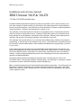
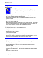
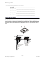
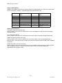
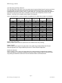
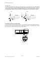
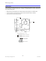
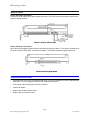
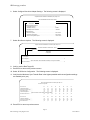
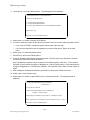
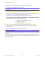
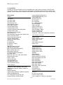
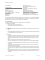
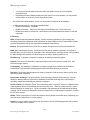
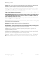
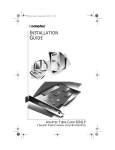
IBM storage products
IBM
Installation and reference manual
IBM Ultrastar 36LP & 36LZX
3.5 inch Ultra 160 SCSI hard disk drive
Models: DPSS-336950
DPSS-318350
DPSS-309170
DDYS-T36950
DDYS-T18350
DDYS-T09170
Page 1
IBM Technology Group Support Center
07N5612IG10
IBM storage products
Technical support
A Troubleshooting section is provided in the Appendix of this manual to aid you in the installation of your
IBM Ultrastar. If the answer to your installation question is not found in this manual, call one of the
Technology Support Centers. Before calling, please gather as much of the following information as
possible:
Ÿ
IBM drive model number, part number, and serial number
Ÿ
Operating system
Ÿ
BIOS manufacturer, version, and date
Ÿ
Any error codes and when they occurred
Ÿ
System type and manufacturer
Ÿ
Chipset manufacturer
Ÿ
Adapter card manufacturer
Ÿ
Other devices in systems
Ÿ
Bus/cable layout (location of device, which device is at the end, etc.)
Ÿ
Applications used (if relevant)
Technology Support Centers:
North America
Web
www.ibm.com/harddrive
Voice 888.426.5214 or 507.286.5825
Fax
507.253.DRIVE
E-mail [email protected]
Singapore
Voice 1800.418.9595 or 65.6.418.9595
E-mail [email protected]
United Kingdom
Voice 44.1475.898.125
E-mail [email protected]
Germany
Voice 49.7032.153050
E-mail [email protected]
Automated Fax Back Service (for related technical support documents)
U.S.A.
408.256.5418
Singapore
800.418.9696
England
0800.96.6948
Germany
0130.82.6089
France
0800.902229
Italy
167.875148
Page 2
IBM Technology Group Support Center
07N5612IG10
IBM storage products
Installation and reference manual
IBM Ultrastar 36LP & 36LZX
3.5 Ultra 160 SCSI hard disk drive
International Business Machines Corporation provides this publication “AS IS” without warranty of any
kind, either express or implied, including, but not limited to, the implied warranties of merchantability or
fitness for a particular purpose. Some states do not allow disclaimers of express or implied warranties in
certain transactions. Therefore, this statement may not apply to you.
This publication could include technical inaccuracies or typographical errors. Product data and specifications are subject to change without notice. Changes are periodically made to the information herein;
these changes will be incorporated in new editions of the publication. IBM may make improvements or
changes in the products or the program described in this publication at any time.
This publication may contain reference to or information about IBM products (machines and programs),
programming, or services that are not available in your country. Such references or information must not
be construed to mean that IBM intends to make available such IBM products, programming, or services
in your country.
Product description data contained herein represents IBM’s design objectives and is provided for comparison among IBM products; actual results may vary based on a variety of factors. Except as explicitly
stated in the Warranty section of this Manual, the product data contained herein does not constitute a
warranty. Questions regarding IBM warranty terms or the methodology used to derive data should be
referred to an IBM representative.
©Copyright International Business Machines Corporation 2000. All rights reserved. Note to US
Government Users - Documentation related to restricted rights - Use, duplication, or disclosure is subject
to restrictions set forth in GSA ADP Schedule Contract with IBM Corp.
IBM is a registered trademark of the International Business Machines Corporation. The following are also
trademarks or registered trademarks of the International Business Machines Corporation in the United
States, other countries, or both: Ultrastar and OS/2. Any other products or trademarks are the property
of their respective owners.
Page 3
IBM Technology Group Support Center
07N5612IG10
IBM storage products
Table of contents
Technical support . . . . . . . . . . . . . . . . . . . . . . . . . . . . . . . . . . . . . . . . . . . . . . . . . . . . . . . . . . . . Page 2
Introduction . . . . . . . . . . . . . . . . . . . . . . . . . . . . . . . . . . . . . . . . . . . . . . . . . . . . . . . . . . . . . . . . . . Page 5
Getting started . . . . . . . . . . . . . . . . . . . . . . . . . . . . . . . . . . . . . . . . . . . . . . . . . . . . . . . . . . . . . . . Page 6
Handling precautions . . . . . . . . . . . . . . . . . . . . . . . . . . . . . . . . . . . . . . . . . . . . . . . . . . . . . . . . . . . Page 6
Tools for installation . . . . . . . . . . . . . . . . . . . . . . . . . . . . . . . . . . . . . . . . . . . . . . . . . . . . . . . . . . . . Page 6
Begin the hardware install . . . . . . . . . . . . . . . . . . . . . . . . . . . . . . . . . . . . . . . . . . . . . . . . . . . . . Page 6
Configure the jumper settings . . . . . . . . . . . . . . . . . . . . . . . . . . . . . . . . . . . . . . . . . . . . . . . . . Page 7
Option jumper blocks . . . . . . . . . . . . . . . . . . . . . . . . . . . . . . . . . . . . . . . . . . . . . . . . . . . . . . . . . . . Page 7
Assign a SCSI address . . . . . . . . . . . . . . . . . . . . . . . . . . . . . . . . . . . . . . . . . . . . . . . . . . . . . . . . . Page 8
Enable optional features . . . . . . . . . . . . . . . . . . . . . . . . . . . . . . . . . . . . . . . . . . . . . . . . . . . . . . . . Page 8
The auxiliary connector on 68 pin models . . . . . . . . . . . . . . . . . . . . . . . . . . . . . . . . . . . . . . . . Page 10
Mount the drive . . . . . . . . . . . . . . . . . . . . . . . . . . . . . . . . . . . . . . . . . . . . . . . . . . . . . . . . . . . . . . Page 11
Attach the cables . . . . . . . . . . . . . . . . . . . . . . . . . . . . . . . . . . . . . . . . . . . . . . . . . . . . . . . . . . . . Page 12
Drives with 68 pin connectors . . . . . . . . . . . . . . . . . . . . . . . . . . . . . . . . . . . . . . . . . . . . . . . . . . . Page 12
Drives with 80 pin connectors . . . . . . . . . . . . . . . . . . . . . . . . . . . . . . . . . . . . . . . . . . . . . . . . . . . Page 12
Complete the hardware install . . . . . . . . . . . . . . . . . . . . . . . . . . . . . . . . . . . . . . . . . . . . . . . . Page 12
Verify host adapter settings . . . . . . . . . . . . . . . . . . . . . . . . . . . . . . . . . . . . . . . . . . . . . . . . . . Page 13
Partition the drive . . . . . . . . . . . . . . . . . . . . . . . . . . . . . . . . . . . . . . . . . . . . . . . . . . . . . . . . . . . Page 16
Format the drive . . . . . . . . . . . . . . . . . . . . . . . . . . . . . . . . . . . . . . . . . . . . . . . . . . . . . . . . . . . . . Page 18
Install the operating system . . . . . . . . . . . . . . . . . . . . . . . . . . . . . . . . . . . . . . . . . . . . . . . . . . Page 18
Appendix . . . . . . . . . . . . . . . . . . . . . . . . . . . . . . . . . . . . . . . . . . . . . . . . . . . . . . . . . . . . . . . . . . .
A. How to create a bootable diskette . . . . . . . . . . . . . . . . . . . . . . . . . . . . . . . . . . . . . . . . . . . .
B. Controller information . . . . . . . . . . . . . . . . . . . . . . . . . . . . . . . . . . . . . . . . . . . . . . . . . . . . . . .
C. Compatibility . . . . . . . . . . . . . . . . . . . . . . . . . . . . . . . . . . . . . . . . . . . . . . . . . . . . . . . . . . . . . .
DDYS models . . . . . . . . . . . . . . . . . . . . . . . . . . . . . . . . . . . . . . . . . . . . . . . . . . . . . . . . . . . .
DPSS models . . . . . . . . . . . . . . . . . . . . . . . . . . . . . . . . . . . . . . . . . . . . . . . . . . . . . . . . . . . . .
D. Troubleshooting . . . . . . . . . . . . . . . . . . . . . . . . . . . . . . . . . . . . . . . . . . . . . . . . . . . . . . . . . . . .
E. Glossary . . . . . . . . . . . . . . . . . . . . . . . . . . . . . . . . . . . . . . . . . . . . . . . . . . . . . . . . . . . . . . . . . .
Page 19
Page 19
Page 19
Page 20
Page 20
Page 21
Page 22
Page 25
Warranty . . . . . . . . . . . . . . . . . . . . . . . . . . . . . . . . . . . . . . . . . . . . . . . . . . . . . . . . . . . . . . . . . . . . Page 26
Page 4
IBM Technology Group Support Center
07N5612IG10
IBM storage products
Introduction
This manual was prepared to aid you in the installation of your new IBM Ultrastar hard disk drive. This
manual provides installation instructions for the following model numbers:
Model
DPSS-336950
DPSS-336950
DPSS-318350
DPSS-318350
DPSS-309170
DPSS-309170
Capacity
36.9 GB
36.9 GB
18.3 GB
18.3 GB
9.1 GB
9.1 GB
Connector Type
68 pin
80 pin SCA
68 pin
80 pin SCA
68 pin
80 pin SCA
DDYS-T36950
DDYS-T36950
DDYS-T18350
DDYS-T18350
DDYS-T09170
DDYS-T09170
36.7 GB
36.7 GB
18.3 GB
18.3 GB
9.1 GB
9.1 GB
68 pin
80 pin SCA
68 pin
80 pin SCA
68 pin
80 pin SCA
Your IBM Ultrastar drive has an advanced Low Voltage Differential (LVD) interface that supports transfer
rates of up to 160 MB/sec. Your drive will function at the maximum speed supported by your system
components.
To obtain the 160 MB/sec transfer rate, an LVD Ultra 160 controller must be used and single-ended
drives cannot be placed on the same cable with LVD drives. If you have a SCSI controller that does not
support this interface, the data transfer speeds of your system will be lower than 160 MB/sec due to the
lower speed of the controller. Contact your controller manufacturer to determine if your current controller
card will support the LVD Ultra 160 interface.
Note: If you currently have single-ended SCSI drives and a non-LVD controller, LVD drives may be
attached to the existing cable. If you choose to replace your non-LVD controller with an LVD controller,
LVD drives can be attached to the same bus with single-ended drives. However, some LVD controllers
do not support single-ended SCSI drives. Contact your controller manufacturer for more information.
Both these configurations will only allow for data transfer speeds at the single-ended rate.
Page 5
IBM Technology Group Support Center
07N5612IG10
IBM storage products
Getting started
Handling precautions
CAUTION! Most hard disk drive damage is caused by poor
handling, physical impact, or electrostatic discharge (ESD). Heeding
the precautions listed below may eliminate the occurrence of such
damage.
Ÿ
To prevent damage from impact or vibration always set the drive down gently.
Ÿ
Do not open the ESD bag containing the drive until required.
Ÿ
Handle the drive carefully by the edges. Do not touch the exposed printed circuit board or any
electronic components.
Ÿ
Do not press on the top or bottom of the drive.
Ÿ
Do not cover the drive’s breather hole.
Ÿ
Before handling the drive, discharge any static electricity from you and your clothing. With one hand
touch an unpainted metal surface on your computer chassis, then touch the ESD bag with the other
hand. Remain in contact with the chassis and the bag for at least two seconds.
Tools for installation
You may need the following items to install the IBM Ultrastar drive.
Ÿ
A small flat-blade screwdriver
Ÿ
A Phillips head screw driver
Ÿ
A small needle-nose pliers or tweezers
Ÿ
Your computer system manual
Ÿ
Operating system startup diskette (see section A. of the Appendix)
Ÿ
Drive rails (Drive rails for 5.25 inch bays may be purchased at your local computer store, from your
system manufacturer, or by calling the IBM Technology Group Support Center.)
Begin the hardware install
Ÿ
Back up the data on the drive currently in your system to prevent data loss during installation.
Ÿ
Turn off your computer system.
Ÿ
Remove cover as instructed by your computer system manual.
Ÿ
Discharge static electricity per instructions given in the Handling Precautions section above.
Ÿ
Unplug your computer.
Ÿ
Note the mounting position of existing drives and cables.
Ÿ
If replacing a drive or cable, remove it. Store the drive in a safe place in case it should be needed
again.
Ÿ
Remove the drive from the ESD bag.
Page 6
IBM Technology Group Support Center
07N5612IG10
IBM storage products
Ÿ
Record the following information for future reference:
Drive model __________________________________________________
Drive part number _____________________________________________
Drive serial number ____________________________________________
Date of purchase ______________________________________________
Place of Purchase _____________________________________________
Configure the jumper settings
Option jumper blocks
The drive has features that are usually enabled by the use of jumpers. A jumper is a small plasticcovered electrical conductor that connects a pair of pins on a jumper block, thereby enabling a particular
function in the drive. Jumpers can be purchased at most computer stores. See the illustration below for
the location of the two jumper blocks which are designated as J4 and J6. Jumper pins have a pitch of
2mm.
J6
J4
+5V
Connected
to 5V via Polyswitch
1
for 68-pin and NC for 80-pin
+5V
Resistor
(150 Ohm)
J4
J6
1
3
5
7
9 11 13
1
3
5
7
2
4
6
8 10 12 14
2
4
6
8 10 12 14
ID Bit 3
ID Bit 2
ID Bit 1
ID Bit 0
Force Mode
Term power (SCSI I/F for 68-pin
models NC for 80-pin models)
To LED pin 8 Aux connector
(68-pin models)
To LED out pin 77
(80-pin models)
9
Reserved
Disable unit
attention
TI sync negotiation
Disable Parity
Delay start 6/12
Auto start delay
Enable auto spin up
(68-pin models)
Disable auto spin up
(80-pin models)
Resistor
68-pin = 150 Ohm
80-pin = 0 Ohm
To Resistor
Collector
Page 7
IBM Technology Group Support Center
07N5612IG10
IBM storage products
Assign a SCSI address
Assign a SCSI address to the drive by placing jumpers on the appropriate pins. Refer to the chart below
for pin combinations. Address 7 is generally reserved for the controller card.
SCSI Address
0
1
2
3
4
5
6
7
Jumpers required on
pins ...
none
7&8
9 & 10
7 & 8, 9 & 10
11 & 12
7 & 8, 11 & 12
9 & 10, 11 & 12
7 & 8, 9 & 10, 11 & 12
SCSI Address
8
9
10
11
12
13
14
15
Jumpers required on
pins ...
13 & 14
7 & 8, 13 & 14
9 & 10, 13 & 14
7 & 8, 9 & 10, 13 & 14
11 & 12, 13 & 14
7 & 8, 11 & 12, 13 & 14
9 & 10, 11 & 12, 13 & 14
7 & 8, 9 & 10, 11 & 12,
13 & 14
Enable optional features
Termination Power (68 pin drives only)
Place a jumper on pins 3 and 4 of option block J4 if your host adapter or other device does not supply
termination power.
Force Single-Ended Mode
Place a jumper on pins 5 and 6 of option block J4 to force the drive to operate in Single-Ended mode.
Enable Auto Spin Up (68 pin drives only)
Place a jumper on pins 1 and 2 of option block J6 to force the drive to spin up automatically after a
power-on reset. If this position has no jumper, the drive will not spin up unless a START UNIT command
is received.
Disable Auto Spin Up (80 pin drives only)
Place a jumper on pins 1 and 2 of option block J6 to prevent the drive from spinning up unless a START
UNIT command is received. If there is no jumper on pins 1 and 2 of J6 the drive will spin up
automatically after a power-on reset.
Page 8
IBM Technology Group Support Center
07N5612IG10
IBM storage products
Auto Start Delay and Delay Start 6/12
The Auto Start Delay option (pins 3 and 4 on option block J6) and the Delay Start 6/12 option (pins 5 and
6 on option block J6) control when and how the drive spins up and comes ready in conjunction with
Enable/Disable Auto Spin up (pins 1 and 2 on option block J6). If Auto Spin up and Auto Start Delay are
jumpered, the spinning up of the drive is delayed by a period of time multiplied by the drive’s SCSI
address. If Auto Spin up is disabled, these jumpers will be ignored.
Note: In the table below ‘on’ means a jumper is installed and ‘off’ means that a jumper is not installed.
Model
68 pin
68 pin
68 pin
68 pin
68 pin
68 pin
68 pin
68 pin
80 pin
80 pin
80 pin
80 pin
80 pin
80 pin
80 pin
80 pin
Auto Spin Up
(Pins 1 & 2)
off
on
off
on
off
on
off
on
off
on
off
on
off
on
off
on
Auto Start Delay Delay Start 6/12
(Pins 3 & 4)
(Pins 5 & 6)
off
off
off
off
on
off
on
off
off
on
off
on
on
on
on
on
off
off
off
off
on
off
on
off
off
on
off
on
on
on
on
on
Auto Start
NO
YES
NO
YES
NO
YES
NO
YES
YES
NO
YES
NO
YES
NO
YES
NO
Delay
Multiplier
0
6
0
12
0
6
0
12
-
Disable SCSI Parity Check
Place a jumper on pins 7 and 8 of option block J6 to disable SCSI Parity Checking.
Enable TI-SDTR
Place a jumper on pins 9 and 10 of option block J6 to enable Target Initiated Wide Data Transfer
Request Negotiation and Target Initiated Synchronous Transfer Request Negotiation.
Disable Unit Attention
Place a jumper on pins 11 and 12 of option block J6 to prevent the drive from building Unit Attention
Sense information for commands immediately following a Power On Reset (POR) or SCSI Bus Reset.
Any pending Unit Attention conditions will also be cleared at POR or SCSI Reset times.
Page 9
IBM Technology Group Support Center
07N5612IG10
IBM storage products
Driving an LED
To drive a Light Emtting Diode (LED) tie the LED Anode to pin 1 of option block J4. Tie the LED Cathode
to pin 2 of option block J4. Using the following illustration make the connections as indicated. Tie pin 2 of
J4 to pin 8 of the Auxiliary connector on the 68 pin model or to pin 77 of the 80 pin connector on the 80
pin model using the 150 Ohm resistor as indicated. This feature does not require the use of a jumper.
80pin
68pin
+5V
+5V
+5V
150 Ohms
Positions #1,#2 on
J-4 Jumper Block
(pin 1 of J-4) to LED Anode
150 Ohms
620 Ohms
(on board) LED
Positions #1,#2 on
J-4 Jumper Block
(pin 1 of J-4) to LED Anode
(pin2 of J-4) to LED Cathode
(pin2 of J-4) to LED Cathode
pin 8 of AUX connector
pin 77 of 80pin connector
150 Ohms
0 Ohms
The auxiliary connector on 68 pin models
The 68 pin models contain an auxiliary connector. This connector conforms to SFF 8009 Rev 3.0 and is
typically used with a unitized connector found on external drive enclosures. The connector has a source
for +5 V dc (pin 11) and a connection (pin 8) for an LED cathode.
Auxiliary Connector
::::::
ID3
ID0
ID2
ID1
7
5 3 1
12 10 8
6 4 2
+5V
11 9
Reserved
Ground
Reserved
LED Cathode
Page 10
IBM Technology Group Support Center
07N5612IG10
IBM storage products
Mount the drive
Note: Drive bays and other enclosures vary in size and orientation from system to system. They may be
oriented vertically, horizontally, upside down, or sideways. The IBM Ultrastar can be mounted with any of
its six surfaces facing down.
Ÿ
Mount the drive as instructed by your computer system manual using four 6-32 UNC screws.
Ÿ
The drive should be mounted securely enough to prevent excessive motion or vibration.
Ÿ
Ensure that the drive has sufficient air flow.
(4X) 6-32 UNC
(2X) 41.28 ±0.5 (2X) 44.45 ±0.2
(2X)
28.5 ±0.5 (2X) 41.6 ±0.2
(2X) 60 ±0.2
(6X) 6-32 UNC
(6X) 6.35 ±0.2
(2X) 95.25 ±0.2
REAR
RIGHT
Recommended torque 0.6 - 1.0 Nm
Max allowable penetration of noted screw
to be 4.5 mm.
Max allowable penetration of noted screw
to be 4.0 mm.
Thickness of bracket
Screw 6-32 UNC
Page 11
IBM Technology Group Support Center
07N5612IG10
IBM storage products
Attach the cables
Drives with 68 pin connectors
Connect the SCSI cable and the power cable to the drive. The SCSI connector and power connector are
keyed for proper insertion.
Drives with 80 pin connectors
80 pin drives are plugged into back planes of servers and require no cables. If you want to connect an 80
pin drive to a 68 pin SCSI cable, a converter is needed. Not all SCA converters support LVD mode.
Complete the hardware install
Ÿ
Ensure that the SCSI bus is terminated at both ends. (LVD SCSI models do not have onboard active
termination. You must supply an external LVD compatible terminator.)
Ÿ
Verify proper cable connection to the SCSI controller.
Ÿ
Connect all cables.
Ÿ
Replace the computer system cover.
Ÿ
Plug the power cord into the wall.
Page 12
IBM Technology Group Support Center
07N5612IG10
IBM storage products
Verify host adapter settings
Note: The example below uses the Adaptec 2940UW controller with DPSS-318350.
1. Insert a bootable diskette into the diskette drive.
2. Turn the computer on. You should see the drive model displayed when the system is booting.
3. Verify the adapter settings.
4. Press [CTRL] [A] to enter the Adaptec SCSI setup utility. The following screen is displayed.
Adaptec AHA-2940 Ultra/Ultra W BIOS v1.23
(c) 1996 Adaptec, Inc. All Rights Reserved.
Press <Ctrl><A> for SCSISelect (TM) Utility!
SCSI ID:LUN NUMBER # : # 0:0 - IBM OEM DPSS-318350
CPU/CLK
Math Coprocessor
Fixed Disk 0
Fixed Disk 1
Fixed Disk 2
:
:
:
:
:
Pentium/133MHz
Installed
None
None
None
- Drive C: (80h)
Base Memory
Extended Memory
Shadow RAM
Internal Cache
External Cache
:
:
:
:
:
640 KB
15360 KB
384 KB
16 KB, Enabled
256 KB, Enabled
5. Press [CTRL] [A] to enter the Adaptec SCSI select utility. The following screen is displayed.
Adaptec AHA-2940 Ultra/Ultra W SCSISelect (TM) Utility v1.23
AHA-2940 Ultra/Ultra W at Bus:Device 00:0Fh
Would you like to configure the host adapter, or run the SCSI disk utilities:
Select the option and press <Enter>. Press <F5> to switch between color and
monochrome modes.
Options
Configure/View Host Adapter Settings
SCSI Disk Utilities
Page 13
IBM Technology Group Support Center
07N5612IG10
IBM storage products
6. Select Configure/View Host Adapter Settings. The following screen is displayed.
Adaptec AHA-2940 Ultra/Ultra W SCSISelect (TM) Utility v1.23
AHA-2940 Ultra/Ultra W at Bus:Device 00:0Fh
Configuration
SCSI Bus Interface Definitions
Host Adapter SCSI ID..................................................................................... 7
SCSI Parity Checking..................................................................................... Enabled
Host Adapter SCSI Termination...................................................................... Automatic
Additional Options
Boot Device Options....................................................................................... Press <Enter>
SCSI Device Configuration............................................................................. Press <Enter>
Advanced Configuration Options.................................................................... Press <Enter>
7. Select Boot Device Options. The following screen is displayed.
Adaptec AHA-2940 Ultra/Ultra W SCSISelect (TM) Utility v1.23
AHA-2940 Ultra/Ultra W at Bus:Device 00:0Fh
Configuration
Boot Device
Configuration
Run SCSI Disk Utilities to get devices
in your system.
Boot Target ID...............................................................................................................................................0
Option Listed Below Have NO EFFECT if Multiple Lun Support is Disabled
Boot Lun Number..........................................................................................................................................0
8. Verify or set the Boot Target ID.
9. Press ESC to return to the previous screen.
10. Select SCSI Device Configuration. The following screen is displayed.
11. Verify that the Maximum Sync Transfer Rate is the highest possible and that configuration settings
are enabled (set to yes).
Adaptec AHA-2940 Ultra/Ultra W SCSISelect (TM) Utility v1.23
SCSI Device Configuration
SCSI Device ID
#0
#1
#2
#3
#4
#5
#6
#7
Initiate Sync Negotiation....................
yes
yes
yes
Maximum Sync Transfer Rate...........
40.0
40.0
40.0
Enable Disconnection........................
yes
yes
yes
Initiate Wide Negotiation...................
yes
yes
yes
Options Listed Below Have NO EFFECT if the BIOS is Disabled
Send Start Unit Command................
yes
yes
yes
yes
40.0
yes
yes
yes
40.0
yes
yes
yes
40.0
yes
yes
yes
40.0
yes
yes
yes
40.0
yes
yes
yes
yes
yes
yes
yes
SCSI Device ID
#8
#9
#10
#11
#12
#13
#14
#15
Initiate Sync Negotiation...................
Maximum Sync Transfer Rate..........
Enable Disconnection.......................
yes
40.0
yes
yes
40.0
yes
yes
40.0
yes
yes
40.0
yes
yes
40.0
yes
yes
40.0
yes
yes
40.0
yes
yes
40.0
yes
12. Press ESC to return to previous screen.
Page 14
IBM Technology Group Support Center
07N5612IG10
IBM storage products
13. Select Advanced Configuration Options. The following screen is displayed.
Adaptec AHA-2940 Ultra/Ultra W SCSISelect (TM) Utility v1.23
AHA-2940 Ultra/Ultra W at Bus:Device 00:0Fh
Configuration
Advanced Configuration Options
Plug and Play Scam Support............................................................................................................................................Enabled
Options Listed Below Have NO EFFECT if the BIOS is Disabled
Host Adapter BIOS (Configuration Utility Reserves BIOS Space)..................................................................................Enabled
Support Removable Disks Under BIOS as Fixed Disks..................................................................................................Boot Only
Extended BIOS Translation for DOS Drives > 1 GByte...................................................................................................Enabled
Display <Ctrl-A> Message During BIOS Initialization......................................................................................................Disabled
BIOS Support for Bootable CD-ROM................................................................................................................................Enabled
BIOS Support for Int13 Extensions...................................................................................................................................Enabled
Support for Ultra SCSI Speed...........................................................................................................................................Enabled
14. Verify that Extended BIOS Translation for DOS Drives > 1 Byte and BIOS Support for int13
Extensions is enabled.
15. Press ESC to return to the previous screen.
16. Exit from Adaptec settings and save any changes.
Page 15
IBM Technology Group Support Center
07N5612IG10
IBM storage products
Partition the drive
Note: This example uses FDISK to partition your drive. You may use a similar partitioning program from
your operating system to partition your drive.
1. Boot to a bootable diskette and type ‘FDISK’ at the A:\ prompt. If Windows 95 OSR2 or Windows 98
is used, the following screen will be displayed.
Your computer has a disk larger than 512 MB. This version of Windows
includes improved support for large disks, resulting in more efficient use of
disk space on large drives, and allowing disks over 2 GB to be formatted as
a single drive.
IMPORTANT: If you enable large disk support and create any new drives on
this disk, you will not be able to access the new drive(s) using other operating
systems, including some versions of Windows 95 and Windows NT, as well as
earlier versions of Windows and MS-DOS. In addition, disk utilities that were
not designed explicitly for the FAT32 file system will not be able to work with
this disk. If you need to access this disk with other
operating systems or older disk utilities, do not enable large drive support.
Do you wish to enable large disk support (Y/N)...............? [N]
2. Type ‘Y’ to select the FAT 32 file system. Type ‘N’ to select the FAT 16 file system. The following
screen is displayed. (If you have more than one drive, a fifth option will appear which allows you to
select the drive to be partitioned.)
Note: Select FAT 32 or FAT 16 if you are using Windows 95 OSR2 or Windows 98. FAT 32
partitions utilize disk space more efficiently and may be greater than 2 GB in size. If you are using
DOS, Windows 3.1x, or an earlier version of Windows 95, select FAT 16.
PC DOS Version 7.0
Fixed Disk Setup Program
Copyright IBM Corporation 1983-1994
FDISK Options
Current fixed disk drive:
1
Choose one of the following:
1. Create DOS partition or Logical DOS Drive
2. Set active partition
3. Delete partition or Logical DOS Drive
4. Display partition information
5. Change current fixed disk drive
Enter choice:[1]
Press ESC to exit FDISK
Page 16
IBM Technology Group Support Center
07N5612IG10
IBM storage products
3.
Select option 1 to create a DOS partition. The following screen is displayed.
Create DOS Partition or Logical DOS Drive
Choose one of the following:
1. Create Primary DOS Partition
2. Create Extended DOS Partition
3. Create Logical DOS Drive(s) in the Extended DOS partition.
Enter choice: [3]
Press ESC to return to FDISK Options
4. Select option 1 to Create a Primary DOS Partition.
5. You will be asked if you want the full capacity of the drive and if you want to make the partition active.
Ÿ
If yes, exit from FDISK. Restart the system and proceed to the next step.
Ÿ
If no, enter the logical drive size in megabytes or percent of disk space. Return to the main
menu.
6. Select option 2 to make the partition active.
7. Press ESC to return to the FDISK options.
8. Create an Extended DOS Partition by selecting option 1 from the main menu and option 2 from the
second menu. Both menus are shown above.
Note: The Maximum Capacity may be smaller than the stated capacity of the drive. This is because
the BIOS of some systems recognizes a Megabyte as 1,048,576 bytes (binary). Drive manufacturers
recognize a Megabyte as 1,000,000 bytes (decimal). The capacities are the same in actual number of
bytes.
9. After creating the Extended DOS Partition, press ESC to return to the FDISK main menu.
10. Select option 1 from the main menu,
11. Select option 3 to create a Logical DOS Drive in an Extended Partition. The following screen is
displayed.
Create Logical DOS Drive(s) in the Extended
DOS Partition
No logical drives defined
Total Extended DOS Partition size is 1047 Mbytes
(1 MByte = 1048576 bytes)
Maximum space available for logical drive is 1047Mbytes (100%)
Enter logical drive size in Mbytes or percent of disk space (%).....[1047]
Press ESC to return to FDISK Options
Page 17
IBM Technology Group Support Center
07N5612IG10
IBM storage products
12. Press ESC to return to the main menu and press ESC again to exit FDISK.
13. Restart the system for the partitions to be recognized.
Format the drive
The drive must be formatted before an operating system can be loaded. Format the Primary partition
and any Extended partitions that have been made by following these steps:
1. After booting from a bootable diskette, run FDISK, option 4 to verify the partition information from the
previous step. Note the drive letters to ensure proper formatting.
2. Press ESC to return to the main menu and press ESC again to exit FDISK.
3. At the A:\ prompt type format x: /s (where x is the drive letter). The /s option makes your hard drive
bootable by copying the system files to the hard drive. If you do not want this drive to be bootable,
do not use the /s switch. The following warning is displayed:
WARNING: ALL DATA ON NON-REMOVABLE
DISK DRIVE C: WILL BE LOST!
Proceed with Format (Y/N)?
4. Type ‘Y’ for yes. The time needed to format the drive depends upon the size of the drive.
5. When the formatting is complete, format the next logical drive by typing format x: (where x is the
logical drive letter).
6. Repeat the above step for each logical drive to be formatted.
Install the operating system
After the drive has been formatted, install an operating system. Follow your operating system installation
instructions.
Note: Some controllers, systems, or operating systems may recognize only ANSI SCSI-2 devices. The
Ultrastar reports itself as a SCSI-3 device. Contact the IBM Technology Group Support Center for a fix if
you encounter this issue.
Page 18
IBM Technology Group Support Center
07N5612IG10
IBM storage products
Appendix
A. How to create a bootable diskette
If you have a bootable Windows operating system, follow the steps below to create a Windows 95 or 98
startup diskette:
1. Insert a blank floppy disk into drive A.
2. From Windows 95 or 98, double click My Computer.
3. Double click Control Panel.
4. Double click Add/Remove Programs.
5. Select Startup Disk tab.
6. Click Create Disk. Follow the prompts.
If you have a bootable DOS operating system, follow the steps below to create a DOS startup diskette:
1. Insert a blank floppy disk into drive A.
2. At the C:\ prompt, type FORMAT A:/S and press ENTER.
3. Follow the instructions displayed.
B. Controller information
The examples in this guide use an Adaptec controller. If a chip set is embedded into your motherboard,
plug the cable into the port on the motherboard instead of the controller.
If you are purchasing an add-on controller card, you will need to install the controller in one of the empty
slots in your computer. Remove the screw holding the metal plate in place and insert the controller into
the appropriate PCI, EISA or ISA slot on the motherboard, making sure the metal plate from the controller fits into the grooves on the computer frame. Replace the screw and connect the SCSI cables to the
controller and then the hard drive. If you have any questions, refer to the installation manual enclosed
with your controller.
Page 19
IBM Technology Group Support Center
07N5612IG10
IBM storage products
C. Compatibility
The IBM SIT Lab tests Ultrastar drives for compatibility with a wide variety of systems, controller cards,
and operating systems. Testing was done to demonstrate compatibility with the following hardware and
software. Other combinations of hardware and software may function with this drive, but were not tested.
DDYS models
Systems
Acer AA12K
Acer Altos 12000
Acer Altos 21000
ALR Revolution 6x6
Apple 6400/180 - Native
Asus P2B-LS (board)
Compaq Destpro 6000
Compaq Deskpro 2000
Compaq Professional Workstation 6000
Compaq Proliant 1500
Dell Dimensions XPS M200s
Dell Precision 610
Dell PowerEdge 4100/200, 6300, 2300 & 1300
Dell PII Xeon (AIC-7890)
Fujistu Siemens Primergy 870
Gateway 2000 NS-8000
Gigabyte GA-6BXS (board)
HP Visualize
HP Kayak ‘IBIS’
HP 9000/712 - Native
HP Cognac
IBM Mpro 6889 (AIC-7895)
IBM Netfinity 3000, 5500
IBM Cherokee 8651TMO Netfinity
IBM PC Server 320 & 704
IBM RS/6000 7024-E30
ICL/Fujitsu G760i (ExtremeRAID)
Intel Sitka Cabrillo
Micron NF 2100, 3101, 3400, 5200 & 6200
Network Engines Viper
SGI 02 - Native
SNI Primergy (460)
SUN SparcStation 20
SUN Ultra30 & Ultra60
Tyan Thunderbolt (board)
SCSI controllers
Adaptec AIC 7880, 7890(AB), 7895 & 7896
Adaptec 2940, 2940UW, 2940AU, 2940U2 &
2940U2W
Adaptec 2950U2B
Adaptec (Mac) 2940U2W, 2940U2/B, 3940UW
Advansys ASB3940U2W
ATTO ExpressPCI UL2S (F/W 135)
Buslogic BT956C, BT958,& BT950
Compaq Wide-Ultra SCSI-2 & 3
Compaq 003654-002 Rev F & K
Centos 4500-U2W
Diamond Fireport 40
DPT 2144UW DPT PM2144W
HP - A4999AultraSCSI
Initio INI-9100UW
Qlogic QLA1080
Qlogic QL1040B rev 2
SUN Sparc 20 - Native
SUN Ultra30&60 - Native
Symbios 53C895 PCI-4
Symbios SYM53C895
Tekram DC - 390U, 390F, 390U2B & 390F/U2W
SCSI Ultra160 controllers
Adaptec 29160
Adaptec 3960D & 39160
Adaptec (Mac) 39160
ATTO UL3D
(LSI) Symbios 53C1010
Qlogic 12160
SCSI RAID controllers
Adaptec AAA-131
Adaptec AAA-131U2
Adaptec ARO1130U2
Adaptec ARO-1130XA
AMIRAID
ASUS DA2100
IBM SeverRAID II
IBM SeverRAID III (+EXP15)
Mylex AcceleRAID 150 & 250
Mylex DAC960PJ
Mylex DAC960PG
Mylex XtremeRAID 1164
Mylex DAC 960PDU
Mylex DAC 960PTL
Mylex DAC 1164P (+EXP200)
SymbiosRAID
ServerRAID2 & 3
Operating Systems
AIX 4.3.2
HP Unix 10.10 & 10.20
IRIX 6.3 & IRIX64 6.5.4f
Linux - RedHat 6.1 & SuSE 6.1 (See Note)
Page 20
IBM Technology Group Support Center
07N5612IG10
IBM storage products
Mac OS 8.0 8.5, 8.6 & 9
Novell Netware v5
MS DOS 6.20
OS/2 Warp4
SCO Unixware 7 & 7.1.1
SCO OpenServer Desktop 5.0.0 & 5.0.2
Solaris 2.6 & 7
Windows NT v4.0 (with Service Pak 5&6a)
Windows 95
Windows 95 (OSR2 OSR2.1)
Windows 98 & Windows 98 (SE)
Windows 2000 x86 Professional (Build 2195)
Windows 2000 x86 Prof Checked (Build 2195)
Windows 2000 x86 Server (Build 2195)
Windows 2000 x86 Adva. Server (Build 2195)
DPSS models
Systems
Acer AA12K
Acer Altos 12000
Acer Altos 21000
ALR Revolution 6x6
Apple 6400/180 - Native
Asus P2B-LS (board)
Compaq Destpro 6000
Compaq Deskpro 2000
Compaq Professional Workstation 6000
Compaq Proliant 1500
Dell Dimensions XPS M200s
Dell Precision 610
Dell PowerEdge 4100/200, 6300, 2300 & 1300
Dell PII Xeon (AIC-7890)
Fujistu Siemens Primergy 870
Gateway 2000 NS-8000
Gigabyte GA-6BXS (board)
HP Visualize
HP Kayak ‘IBIS’
HP 9000/712 - Native
HP Cognac
IBM Mpro 6889 (AIC-7895)
IBM Netfinity 3000, 5500
IBM Cherokee 8651TMO Netfinity
IBM PC Server 320 & 704
IBM RS/6000 7024-E30
ICL/Fujitsu G760i (ExtremeRAID)
Intel Sitka Cabrillo
Micron NF 2100, 3101, 3400, 5200 & 6200
Network Engines Viper
SGI 02 - Native
SNI Primergy (460)
SUN SparcStation 20
SUN Ultra30 & Ultra60
Tyan Thunderbolt (board)
SCSI controllers
Adaptec AIC 7880, 7890(AB), 7895 & 7896
Adaptec 2940, 2940UW, 2940AU, 2940U2 &
2940U2W
Adaptec 2950U2B
Adaptec (Mac) 2940U2W, 2940U2/B, 3940UW
Advansys ASB3940U2W
ATTO ExpressPCI UL2S (F/W 135)
Buslogic BT956C, BT958,& BT950
Compaq Wide-Ultra SCSI-2 & 3
Compaq 003654-002 Rev F & K
Centos 4500-U2W
Diamond Fireport 40
DPT 2144UW DPT PM2144W
HP - A4999AultraSCSI
Initio INI-9100UW - to test
Qlogic QLA1080
Qlogic QL1040B rev 2
SUN Sparc 20 - Native
SUN Ultra30&60 - Native
Symbios 53C895 PCI-4
Symbios SYM53C895
Tekram DC - 390U, 390F, 390U2B & 390F/U2W
SCSI Ultra160 controllers
Adaptec 29160
Adaptec 3960D & 39160
Adaptec (Mac) 39160
ATTO UL3D
(LSI) Symbios 53C1010
Qlogic 12160
SCSI RAID controllers
Adaptec AAA-131
Adaptec AAA-131U2
Adaptec ARO1130U2
Adaptec ARO-1130XA
AMIRAID
ASUS DA2100
IBM SeverRAID II
IBM SeverRAID III (+EXP15)
Mylex AcceleRAID 150 & 250
Mylex DAC960PJ
Mylex DAC960PG
Mylex XtremeRAID 1164
Mylex DAC 960PDU
Mylex DAC 960PTL
Mylex DAC 1164P (+EXP200)
SymbiosRAID
Page 21
IBM Technology Group Support Center
07N5612IG10
IBM storage products
ServerRAID2 & 3
SCO Unixware 7 & 7.1.1
SCO OpenServer Desktop 5.0.0 & 5.0.2
Solaris 2.6 & 7
Windows NT v4.0 (with Service Pak 5&6a)
Windows 95
Windows 95 (OSR2 OSR2.1)
Windows 98 & Windows 98 (SE)
Windows 2000 x86 Professional (Build 2195)
Windows 2000 x86 Prof Checked (Build 2195)
Windows 2000 x86 Server (Build 2195)
Windows 2000 x86 Adva. Server (Build 2195)
Operating Systems
AIX 4.3.2
HP Unix 10.10 & 10.20
IRIX 6.3 & IRIX64 6.5.4f
Linux - RedHat 6.1 & SuSE 6.1 (See Note)
Mac OS 8.0 8.5, 8.6 & 9
Novell Netware v5
MS DOS 6.22
OS/2 Warp4
Note: Linux Kernel requires the aic7xxx (Adaptec) driver to be at level 5.1.22 or greater (all compatibility
testing performed at 5.1.28). Some Linux Kernels may not contain drivers to support OEM SCSI cards.
Check with your Linux supplier for SCSI card hardware compatibility.
D. Troubleshooting
Following is a useful checklist to assist in rectifying common SCSI problems:
ü SCSI ID (device address):
Ÿ Each device must have a unique SCSI ID.
Ÿ
Recommended SCSI ID for the boot device is 0.
ü Interface type:
Ÿ If you have more than one SCSI device on the cable, make sure that all devices are of the same
type.
Ÿ
High Voltage Differential (HVD) SCSI devices are not compatible with single-ended (standard) or
Low Voltage Differential (LVD) SCSI devices.
ü Termination:
Ÿ SCSI systems should have termination at both ends of the cable. Make sure that the controller
terminates one end of the cable and that a drive supplies termination at the other end. If a drive
doesn’t have onboard termination, a terminator should be placed on the last connector of the
cable.
Ÿ
Make sure that there is no extra cable after the terminator at the end.
Ÿ
Any device attached that is not at the end of the cable must have internal termination disabled.
Ÿ
For adapters with multiple SCSI ports with differing performance, ALL ports must be correctly
terminated.
Ÿ
For adapters with a common port with both internal and external connections in use, DO NOT
enable termination on the controller.
Ÿ
Narrow (50 pin) devices SHOULD NOT be connected at the end of a wide (68 pin) SCSI cable.
A terminator in a 50 pin SCSI device cannot provide the correct termination for the unused data
lines.
Ÿ
Using a 68-50 pin cable converter to connect a 68 pin drive to a 50 pin SCSI adapter could cause
problems because the 68-50 pin cable converter leaves 18 of the 68 pins on the drive without
termination.
Page 22
IBM Technology Group Support Center
07N5612IG10
IBM storage products
Resolution:
Place the 68 pin drive at the end of the bus and set the jumpers for the drive for active
termination, which provides termination to all 68 pins. If the drive does not provide termination,
the converter should provide on board termination so that all unused lines are terminated.
Ÿ
The termination for a drive should match the interface type of the drive. For example,
single-ended drives should use single-ended terminators
ü Cables and connectors
Ÿ Ensure that the cables are seated tightly and that no pins are bent.
Ÿ
If possible, try replacing the cable and terminators and use the drive’s internal termination.
Ÿ
Make sure that pin 1 of the cable is plugged into pin 1 of the SCSI connector. Pin 1 on the SCSI
cable is normally identified by a red or red-striped wire. This is especially important if you are
using cables or connectors (on the SCSI adapter) that are not keyed. The connectors on IBM
drives have a slotted key to prevent you form plugging the cable in backwards but not all SCSI
cables are made with a key.
ü Ensure that the drive is jumpered to enable auto start when power is applied.
ü Try resetting the SCSI adapter defaults:
Ÿ Enable “Reset IC Initialization”
Ÿ
Disable “plug and play” SCAM support
Ÿ
Enable “Unit Start” command
Ÿ
Enable synchronous and wide negotiations if available
ü Ensure that the drive is jumpered to disable sync negotiations.
ü Does the drive spin up and remain spinning?
ü Does the SCSI adapter recognize the drive during boot up?
ü Check that the cable lengths are within the ANSI specification for the interface transfer rate used and
the number of devices installed on the bus. For a definition of the specifications, see the SCSI Trade
Association page at the following Internet address:
http://www.scsita.org/terms/scsiterms.html
ü If the drive is attached through a removable carrier, try removing the drive from the carrier and
attaching the drive directly to the bus.
ü If you are using a narrow bus/cable (50 pin) with a wide (68 pin) device and a wide SCSI adapter, try
disabling wide negotiation in the adapter settings.
ü LVD devices are backward compatible with single-ended adapters as long as the system and the
drives are configured correctly. When attaching LVD devices to single-ended, wide or narrow
adapters, the following applies:
Ÿ
LVD drives have do not provide termination on the drive.
Page 23
IBM Technology Group Support Center
07N5612IG10
IBM storage products
Ÿ
You must provide termination externally, either from another device or from a separate
termination block.
Ÿ
Depending on how the adapter handles the “Diff Sense” line on the interface, you may need to
set the jumper on the drive to Force Single Ended mode.
ü On multi-channel SCSI adapters, do not use more than two channels off each adapter.
ü In RAID environments, it is important to disable SCAM.
Ÿ Disable at the adapter, if available.
Ÿ
Disable at the drive. This is only necessary with the DORS-3xxxx, DCAS-3xxxx and
DDRS-3xxxx family of SCSI drives. Newer drives have SCAM disabled as default or removed
completely.
E. Glossary
ANSI (American National Standards Institute). ANSI is the lead organization for encouraging and
developing technological standards. ANSI represents the United States in the IEC (International Electrotechnical Commission) and the ISO (International Standards Organization).
Backup Storing information from a hard drive to another storage area in order to prevent data loss.
BIOS (Basic Input/Output System) The BIOS is the first level of software contained in a computer. It
provides basic, low level control for keyboards, video, hard disk drives, and floppy drives. It also provides
the initial intelligence that allows the computer system to find an operating system to run.
Boot/Boot-up To prepare a computer for operation by loading an operating system.
Capacity The amount of information, expressed in bytes, that can be stored on a hard drive. Also
known as storage capacity.
Compatibility The capability of a hardware or software component to conform with the interface
requirements of a given data processing system without adversely affecting its functions.
Disk drive The primary data storage device used by computers. Disk drives are used to record, store
and retrieve digital information.
Electrostatic discharge The rapid change in electrical energy caused by static electricity. This can
damage or destroy electronic equipment or hardware. Electrostatic discharge can be prevented by
grounding oneself before handling any electronic equipment.
FAT16 & FAT32 (File Allocation Table) The file allocation table is a group of sectors in a hard drive that
contains address chains for the different files on a hard disk drive. There are usually two FATs (kept in
different locations) on a hard drive. FAT32 is available in the Windows® 95 & Windows® 98 operating
systems. FAT32 receives its designation because it allows 32 bits of addressing as opposed to 16 bits in
the FAT16 file system.
FDISK FDISK is a program run in DOS that allows a user to partition a hard disk drive. Partitioning your
hard disk drive is essential for it to work properly.
Format To prepare a hard drive so that it can store data. In the DOS formatting process, the computer
verifies the clusters within a partition.
Page 24
IBM Technology Group Support Center
07N5612IG10
IBM storage products
Hard disk drive (HDD) A stand alone disk drive that reads and writes data onto rigid disks and can be
attached to a port on the system unit. Synonymous with fixed disk drive and hard drive.
Interface A hardware or software protocol, contained in the electronics of the disk controller and drive,
that manages the exchange of data between the hard disk drive and the computer. The most common
interfaces for small computer systems are ATA (IDE) and SCSI.
Jumpers A small electrical conductor covered with plastic that connects a pair of pins on a jumper block,
thereby enabling a particular function in the drive.
Jumper settings Different modes which are achieved by placing a jumper on a particular pair of pins on
a device. These modes determine the behavior of the device. Settings are changeable by the user, but
remain constant during operation. See Jumpers.
LVD (Low Voltage Differential) A highly compatible computer disk drive interface that is faster and more
reliable than SCSI. Also known as Ultra2 SCSI.
Motherboard Holds the computer’s main processors and circuitry, and also contains the memory, BIOS,
interconnection circuitry and expansion slots.
Multimode A drive that can operate on an LVD bus or a Single-ended bus.
Operating system Software that controls the execution of programs and may provide functions such as
resource allocation, scheduling, input/output control, and data management. Although operating systems
are predominantly software, partial hardware implementations are possible.
Partition A portion of a hard drive dedicated to a particular operating system or application and
accessed as a single logical volume.
SCSI (Small Computer System Interface) An intelligent parallel peripheral interface characterized by
its use of high level communication between devices. Pronounced “scuzzy”.
Termination The signals on a SCSI bus must be terminated at both ends of the bus. This is generally
done by the controller automatically and requires an “external” terminator on the last connector of the
bus.
Page 25
IBM Technology Group Support Center
07N5612IG10
IBM
®
© International Business Machines Corporation
2000
www.ibm.com/harddrive
IBM Technology Group Support Center
Telephone: 888.426.5214 or 507.286.5825
E-mail: [email protected]
Singapore Technology Group Support Center
Telephone: 1800.418.9595 or 65.6.418.9595
E-mail: [email protected]
UK Technology Group Support Center
Telephone: 44.1475.898.125
E-mail: [email protected]
Germany Technology Group Support Center
Telephone: 49.7032.153050
E-mail: [email protected]
IBM Storage Systems Division
5600 Cottle Road
San Jose, CA 95193
www.ibm.com/storage
Printed in the United States of America
09-2000
All Rights Reserved
IBM is the registered trademark and Deskstar is a trademark of
International Business Machines Corporation.
Other company, product, and service names may be trademarks or
service marks of others.
Produced by the IBM Technology Group Support Center.
This information is believed to be accurate, but is supplied without
guarantee. Document subject to change without notice.
7 September, 2000
Page 26
IBM Technology Group Support Center
07N5612IG10