1
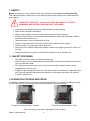
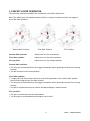
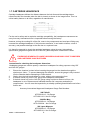
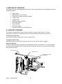
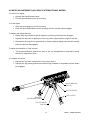
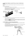
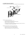
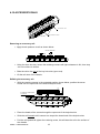
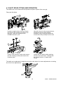
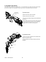
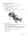
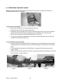
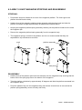
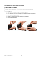
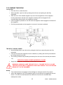
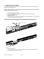
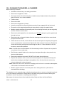
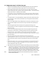
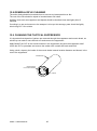
AXMC Rifle USER MANUAL Accuracy International Ltd. Portsmouth. UK. Tel + 44 (0) 23 92 67 1225 Fax + 44 (0) 23 92 69 1852 Email: [email protected] Accuracy International of North America inc. Fredericksburg, VA, USA. Tel + 1 540 368 3108 Fax + 1 540 368 3109 Email: [email protected] www.accuracyinternational.com AI-15591 Issue 1A ACCURACY INTERNATIONAL Accuracy International was formed in 1978 to design and build tactical rifles. The original design ethos combined two factors into a unique package. Namely the incorporation of performance enhancing features learned in Olympic and international target shooting onto a platform exhibiting full military ruggedness. The current designs faithfully follow this original concept, but also benefit from over twenty years of continuous improvement. These improvements are not cosmetic, but are driven solely by the needs of the users, highly trained military and police units in over 60 countries worldwide. Such units are exposed to ‘live’ tactical situations on a daily basis and in the most demanding environments where first shot accuracy is critical. The rifles are produced in a purpose built 20,000sq. ft. facility in the UK, operating a management system certified to BS EN ISO9001:2008. All components are manufactured to Accuracy International’s designs to ensure that they are optimised for the function they must perform, something that cannot be achieved with a ruggedized-sporting weapon. The AXMC sniper rifle is an evolution, which builds on Accuracy International’s established family of highly successful AW rifles. A bolt-action single shot rifle with free-floating barrel and a magazine capacity of ten rounds fulfils the need for a highly accurate long range sniper rifle. Like the AW series, all AX rifles utilise an aluminium chassis system, which ensures insensitivity to temperature and humidity, thus ensuring a constant zero. The forend tube design provides multiple mounting points for accessory rails, sling attachments and bipod mounts. The AXMC rifle is easily upgradeable with a number of accessories and upgrades which can be purchased from Accuracy International distributors. AXMC - USER MANUAL 2 CONTENTS 1. SAFETY 4 1.1 SAFETY FEATURES 4 1.2 FIRING PIN COCKING INDICATOR 4 1.3 SAFETY LEVER OPERATION 5 1.4 SAFETY PRECAUTIONS 6 1.5 WARNINGS 7 1.6 SAFETY LEVER - FIELD SAFETY CHECK 7 1.7 CARTRIDGE HEADSPACE 8 2. PARTS IDENTIFICATION 9 3. TECHNICAL SPECIFICATION 9 4. SETTING UP THE RIFLE 10 4.1 HEX KEY STORAGE 10 4.2 BIPOD ADJUSTMENT (AI MODEL) 11 4.3 BIPOD FITTING AND REMOVAL (AI MODEL) 12 4.4 BIPOD FITTING AND REMOVAL (HARRIS MODEL) 12 4.5 CHEEKPIECE ADJUSTMENTS 13 4.6 BUTT PAD ADJUSTMENTS 14 4.7 BUTT SPACER FITTING 15 4.8 REAR GRIP POSITION ADJUSTMENT 16 4.9 SCOPE MOUNT ADJUSTMENT 17 4.10 ACCESSORY RAILS 18 4.11 BUTT SPIKE FITTING AND OPERATION 19 5. FOLDING THE STOCK 20 6. FIELD STRIPPING THE RIFLE 21 6.1 STRIPPING THE BOLT ASSEMBLYY 22 6.2 AXMC MAGAZINE STRIPPING AND REASSEMBLY 23 7. PREPARING AND FIRING THE RIFLE 24 7.1 MAGAZINE LOADING 24 7.2 LOADING THE RIFLE 25 7.3 FIRING AND OPERATING THE RIFLE 26 7.4 UNLOADING THE RIFLE 27 7.5 FITTING AND REMOVING THE TACTICAL SUPPRESSOR 28 8. STOPPAGE AND TROUBLESHOOTING DRILLS 29 9. TELESCOPIC SIGHT ADJUSTMENTS 31 9.1 ZEROING THE TELESCOPIC SIGHT 32 10. CALIBRE CONVERSION & CHANGING THE BARREL 33 11. REMOVING THE FOREND 36 12. USER LEVEL MAINTENANCE 37 13. BARREL BREAK-IN PROCEDURE 43 3 AXMC - USER MANUAL 1. SAFETY Before attempting to use or handle the rifle, this manual must be read and understood fully. This manual assumes a basic level of user familiarity with firearms and is not a replacement for user training. DAMAGE TO PROPERTY, INJURY OR DEATH MAY RESULT IF SAFETY WARNINGS AND INSTRUCTIONS ARE NOT FOLLOWED. Always keep the weapon pointed in a safe direction during handling. Never leave a weapon unattended. Always wear suitable eye and hearing protection when firing the weapon. Always check the barrel, muzzle brake and suppressor, where fitted, are clear of debris and obstructions before firing. Never attempt to clear an obstruction by firing. Always use quality factory ammunition of the correct calibre for the weapon. Clearly identify your target and what is beyond it. When the rifle is loaded, always keep fingers outside of the trigger guard until a shot is to be fired. Always show that the weapon is clear before handing it over to another user. 1.1 SAFETY FEATURES The AXMC rifle bolt utilises six forward locking lugs. When the bolt is in the closed position the bolt head is enclosed and supported within the lock ring and action body. The firing pin cannot protrude from the front of the bolt face unless the bolt lugs are engaged within the lock ring. Dangerous gas leakage from the rear of the action body is minimised by a tight fitting bolt and a shroud assembly that assists the deflection of hot gases away from the operator. 3-position safety lever. 1.2 FIRING PIN COCKING INDICATOR It is possible to determine if the Accuracy International AXMC rifle is ‘cocked’ and therefore ready to fire by the position of the firing pin protruding through the rear of the shroud. Firing Pin Cocking Indicator ‘Cocked’ Firing Pin Cocking Indicator ‘Fired’ Note: The firing pin has been highlighted in red for clarity. AXMC - USER MANUAL 4 1.3 SAFETY LEVER OPERATION The Accuracy International AXMC rifle is fitted with a 3-position safety lever. Note: The safety lever only operates when the rifle is ‘cocked’ and does not block the trigger in any of the three positions. ‘Second Safe’ Position ‘First Safe’ Position ‘Second Safe’ position - Safety lever is in the rear position ‘First Safe’ position - Safety lever is in the centre position ‘Fire’ position - Safety lever is in the forward position ‘Fire’ Position ‘Second Safe’ position: The firing pin is drawn back from the trigger mechanism and is physically blocked from moving forward. The bolt is locked in the closed position ‘First Safe’ position: To apply the ‘first safe’ position the lever must be brought back to the ‘second safe’ position then moved forward to the ‘first safe’ position. The firing pin is drawn back from the trigger mechanism and is physically blocked from moving forward. The bolt is unlocked and may be used to unload cartridges in a safe manner. ‘Fire’ position: The bolt is unlocked and can be manipulated. The firing pin is not blocked and the weapon can be fired. 5 AXMC - USER MANUAL 1.4 SAFETY PRECAUTIONS WARNING - Users and personnel responsible for the weapon must comply with the following SAFETY PRECAUTIONS. For the purposes of health and safety, all warnings and cautions must be adhered to. Safety precautions should be carried out: On initial receipt of the weapon. Before use. After use. Before maintenance or cleaning procedures Before any inspection procedure. Before any non tactical movements. Prior to the weapon being placed in a transit case or drag bag. When the documentation recommends it. SAFETY PRECAUTIONS: Hold the weapon securely, do not place finger inside trigger guard. Point the weapon in a safe direction. Remove magazine (if fitted). Check that the safety is in the ‘fire’ position. Orientate the ejection port downwards and open the bolt and slide to rear. Watch for a live cartridge or empty case ejecting Inspect the chamber and bolt face for a live cartridge or empty case. Visual Check - Look through the ejection port. Physical Check - Use a finger to check the chamber and bolt face. Remove any cartridge or case from the weapon. With the bolt left ‘open’, the rifle is now safe to handle. Where possible, the bolt should be left ‘open’ to identify to others that it is safe. However, should the bolt be required in the ‘closed’ position: Pull and hold the trigger while closing the bolt. Fit an empty magazine, if required. The rifle is now safe to handle. WARNING - DANGER TO LIFE AND LIMB: IF THE BOLT IS NOT FULLY CLOSED WHEN THE RIFLE IS FIRED, THE COCKING PIECE COULD STRIKE THE BOLT CAUSING POSSIBLE MISFIRES. The extractor does not engage the cartridge rim unless the bolt is fully closed. Failure to fully close the bolt every time it is manipulated may result in a live round being left in the chamber. Attempting to load a second round will result in a stoppage. This is known as “double feeding”. AXMC - USER MANUAL 6 1.5 WARNINGS THE USE OF MISMATCHING ‘FIRING TRAIN’ PARTS AND ASSEMBLIES POSES A SERIOUS RISK TO LIFE AND LIMB. DO NOT FIRE THE RIFLE IF THE SERIAL NUMBERS OF THE ACTION BODY, BOLT AND BOLT / FIRING PIN ASSEMBLY DO NOT MATCH. WEAPON STATUS. When the users are not aware of the weapon status, i.e. loaded, unloaded, cocked or fired, the user must assume the weapon is LOADED and carry out the SAFETY PRECAUTIONS set out in section 1.4. HANDING OVER WEAPONS. A weapon which is to be handed over to another individual must be unloaded and presented with the bolt in the ‘open’ or rearwards position. TACTICAL MOVEMENTS. Tactical movements with a loaded weapon are only to be performed with the safety lever on ‘2nd safe’ position. WARNING - DANGER TO LIFE AND LIMB: THE TRIGGER UNITS FITTED INTO ACCURACY INTERNATIONAL RIFLES ARE DESIGNED AND FACTORY SET AS TWO-STAGE TRIGGERS. THEY MUST NOT BE ADJUSTED UNDER ANY CIRCUMSTANCES INTO A SINGLE STAGE TRIGGER. TRIGGER UNITS SHOULD ONLY BE ADJUSTED IN ACCORDANCE WITH ‘APPROVED’ ACCURACY INTERNATIONAL MAINTENANCE MANUALS. FAILURE TO COMPLY WITH THIS WARNING COULD RESULT IN SERIOUS INJURY OR DEATH. 1.6 SAFETY LEVER - FIELD SAFETY CHECK The following procedure should be carried out before each time the rifle is used to ensure the safety lever is functioning correctly . This does not replace the need to have the safety mechanism routinely tested in accordance with the Accuracy International Maintenance Manual. Ensure the weapon is unloaded and safe to handle. With the bolt assembly fitted into the action body, open then close the bolt leaving it in the cocked position. Move the safety lever into the ‘1st safe’ position. See section 1.3. Pull then release the trigger six times, remove your finger from the trigger. Push the safety lever forward into the ‘FIRE’ position. The firing pin should not be released, but still be retained by the safety mechanism. Pull the trigger to release the firing pin. Repeat this process two or three times to confirm that the system is safe. If the firing pin is released when the safety lever is moved to the fire position the rifle is deemed unsafe and must be returned to an Accuracy International trained armourer or gunsmith for maintenance in accordance with the Accuracy International maintenance manual. 7 AXMC - USER MANUAL 1.7 CARTRIDGE HEADSPACE Cartridge headspace defines the distance between the bolt face and the cartridge datum reference within the chamber when the bolt is closed, as shown in the image below. This is a critical safety feature on all rifles, regardless of manufacturer. For the user’s safety and to maximise cartridge compatibility, the headspace measurement on every Accuracy International rifle is inspected before leaving the factory. However, during the working life of the rifle, wear to key components and new barrel fitting may increase the cartridge headspace. If this becomes excessive, it can lead to misfires, a loss of accuracy, and possible damage to the rifle due to a ruptured case. It is therefore essential to check the cartridge headspace using Accuracy International specification gauges throughout the life of the rifle, particularly after a new barrel is fitted. EXCESSIVE HEADSPACE CAN BE HAZARDOUS AND MAY LEAD TO MISFIRES AND CARTRIDGE CASE RUPTURES Instructions for checking the headspace dimension: Headspace gauges are used to specify a maximum headspace for safety purposes using ‘GO’ and ‘NO GO’ gauges. 1. 2. 3. 4. Ensure the chamber is clean before inserting the gauge into the chamber through the ejection port. Note: - To prevent damaging the chamber, ensure the gauge is fully inserted into the chamber before attempting to close the bolt. Gently close the bolt handle down to a stop, without using excessive force. If the bolt closes fully on the ‘GO’ gauge the headspace is acceptable. If the bolt closes fully on the ‘NO GO’ gauge using a minimum amount of force, the headspace is out of tolerance and indicates that the rifle’s accuracy and safety is compromised – the rifle must be inspected by a suitably qualified gunsmith/armourer before further use. Accuracy International Approved Headspace Gauge Part Numbers: .308/7.62x51 AITG-0010-A3 - Go Gauge AITG-0011-A3 - No-Go Gauge .300 Win Mag AITG-3395-A4 - Go Gauge AITG-3399-A4 – No Go Gauge AXMC - USER MANUAL .338 Lapua Magnum AITG-0050-A3 - Go Gauge AITG-0051-A3 - No Go Gauge 8 2. PARTS IDENTIFICATION CHEEK PIECE ACTION RAIL SHROUD ACCESSORY RAIL FOREND RAIL MUZZLE BRAKE BIPOD ADAPTER ADJUSTABLE BUTT REAR GRIP TRIGGER SHOE MAGAZINE BIPOD 3. TECHNICAL SPECIFICATION Calibre : .338 Lapua Magnum (May be converted to .300 Win mag or .308 Winchester) Action : Front Locking, 6 lugs. Bolt : 60 degrees opening, 6 mm striker fall. Trigger : 2-stage, adjustable, set between 1.5 to 2 Kg (3.3lbs - 4.4lbs). Adjustable for reach. Barrel : 20 / 27” Stainless match-grade; 1 in 9.35” twist. Safety : 3-position safety draws back and retains the firing pin, and depending on the safety position, either locks the bolt closed or allows it to be cycled in a ‘safe’ condition. Stock : Folding stock, fitted with Adjustable Cheek Piece and Butt (length of pull and height). Optic rail : 30 MOA STANAG Rail. Magazine : 10 shot, double-stack, detachable, box-type magazine. Butt Spike : Optional Quick and fine adjustment, offering 38mm overall height adjustment Rear Grip : Rail or Butt Mounted. Can be exchanged with the butt spike module Handstop : Optional, adjustable for position. Incorporates one ‘Flush Cup’ Sling Point Accessory Rails : 2 x 80mm Accessory Rails, 1 x 140mm Accessory Rail. Sling Points : ‘Flush Cup’ sling points fitted. Length : 128cm (50.4”) - with butt adjustment fully extended (excl. spacers) 103cm (40.6”) - with butt folded. Weight : 6.8kg (15lbs) with a 12 o’clock MIL-STD 1913 rail, and unloaded magazine. *This excludes the bipod, scope sight and additional accessory rails. Butt Spacer Kit : 1 x 20mm and 1 x 10mm Spacers Usage : Designed for all uses up to and including military use in extreme environmental conditions. 9 AXMC - USER MANUAL 4. SETTING UP THE RIFLE The AXMC rifle has been designed so that many of the user interfaces can be adjusted to suit the individual operator: Bipod height Bipod position on the forend Cheek Piece height and lateral position Length of pull Trigger reach Butt Pad height and angle Rear Grip position Scope position Butt spike height Accessory Rail/Flush Cup Sling Points 4.1 HEX KEY STORAGE The majority of adjustments on the rifle are carried out using a 4mm Hex Key. For the convenience of the user, a suitable Hex Key is stored within the Cheek Piece of the rifle. To remove the Hex Key: Use a finger to push the Hex Key out of the Cheek Piece To replace the Hex Key: Offer the Hey Key up to the slot and push into the recess until the detent engages. 1 A Using the Hex Key: Avoid over tightening the screws as this may damage the rifle or accessories. It is often possible to achieve an acceptable level of torque using the long end of the key in the screw and using the short end as the lever. 2 3 4 This drawing contains confidential information belonging to ACCURACY INTERNATIONAL LIMITED. The recipient acknowledges that the copyright & design right in this drawing belong to & remains vested in ACCURACY INTERNATIONAL LTD. No license is given by ACCURACY INTERNATIONAL LTD for the recipient to copy or make use of the information contained in thisdrawing. The recipient shall maintain the confidentiality of the drawing. 4mm HEX KEY 5 6 7 DRAWING PROCEDURE TO DEF. STAN. 05-10 AND/OR BS 8888. (1) ALL BURRS & SHARP EDGES TO BE REMOVED. (2) A RADIUS OR CHAMFER OF 0.2 (MAX) IS PERMITTED IN THE CORNERS OF BLIND HOLES, RECESSES & STEPS. (3) REFERENCES TO STANDARDS & SPECS. IMPLY LATEST ISSUE. 8 9 10 (4) ALL DIMENSIONS ARE FINISHED DIM'NS. i.e. AFTER APPLICATION OF SURFACE FINISH (5) DRAWING FEATURES MARKED THUS 3 INDICATE LATEST ISSUE MODIFICATION. (WHERE NUMBER IN BOX IS APPLICABLE CHANGE) (6) UNLESS OTHERWISE STATED, ALL TAPPED HOLE THREAD FORMS ARE TO BS 3643-6H. WHERE A THREAD DEPTH IS QUOTED, IT IS MINIMUM FULL THREAD DEPTH. HEX KEY SLOT B PUSH HEX KEY HERE TO REMOVE C D E F G H J PRELIMINARY NOT CHECKED NOT RELEASED K CERT'D DIMENSIONS DISPLAYED THUS ARE INSPECTION DIMENSIONS CHECKED L 0 DRAWN/DATE 20 MATERIAL (AND SIZE) SPECIFICATION AXMC - USER MANUAL FINISH 3rd Angle Projection 50 N/A 100 TOLS: (UNLESS OTHERWISE STATED) SEE ITEMS LIST 30.00 SPECIFICATION UNIT ± 0.5 .0 ± 0.25 .00 ± 0.1 ANG ±0 15' SURFACE ROUGHNESS (UNLESS OTHERWISE STATED) N7 ORIGINAL SCALE TITLE 1:1 10 ESTIMATED MASS g DIM'N IN mm RLR NORWAY 338 LAP MAG, GA RESPONSIBLE AUTHORITY AND C NATO STOCK No: ACCURACY INTERNATIONAL LAST BY: CHANGE: DRAWING NUMBER AI-26581 CH'NGE DATE: ISSUE SH'T 1 OF 1 A 3 5 4.2 BIPOD ADJUSTMENTS (ACCURACY INTERNATIONAL MODEL) 6 7 8 9 To remove the bipod: Operate the bipod release catch. Pull the bipod forward out of its mounting. AND To SCOPE fit the bipod: SCOPE MOUNT Offer the bipod spigot up to the mounting. Push the bipod backwards into the mounting until the release catch engages. MUZZLE BRAK FOREND RAIL 30 MOA To deploy and adjust the legs: Rotate each leg round through 90 degrees until the leg locking button engages. Depress the leg catch to deploy the inner leg, while supporting the weight of the rifle. Alternatively the leg can be pulled down to find the desired height once the first locking position has been disengaged. To adjust the bipod tilt or ‘Cant’ tension: The tension/resistance against the ‘cant ‘or ‘loll’ can be tightened or loosened by using BIPOD BIPOD the tension adjustment MOUNT knob. To collapse the bipod: Depress the leg catch and push the inner leg(s) fully in. Depress the leg locking button and rotate the leg forwards or rearwards until the detent pin engages. BIPOD RELEASE CATCH BIPOD SPIGOT LEG CATCH TENSION ADJUSTMENT KNOB LEG LOCKING BUTTON 11 AXMC - USER MANUAL 4.3 BIPOD MOUNT REMOVAL AND REFITTING (ACCURACY INTERNATIONAL MODEL) The Bipod Mount may be repositioned along the length of the forend using the key hole slot system. BIPOD MOUNT RETAINING SCREWS EXTENDED BIPOD MOUNT RETAINING SCREWS Apply Pressure 5mm To remove the Bipod Mount: Apply pressure to the bipod mount as shown below. Using the supplied 4mm Hex Key, loosen the two retaining screws until light resistance is felt (then stop, do not continue to loosen). Slide the bipod mount to the rear of the key hole slots (open end). FOREND RETAINING SCREWS Lift the bipod mount clear of the chassis. To fit the Bipod Mount: With the retaining screws in the extended position shown above, insert the flared ends of the screws into the desired keyhole slots. Slide the mount forwards until it comes to a stop at the closed end of the key hole slots. Pull the mount upwards & tighten the retaining screws using the 4mm hex key, this will draw the mount to the surface of the chassis. 4.4 BIPOD REMOVAL AND REFITTING (HARRIS BIPOD). To remove the bipod, loosen the retaining screw, then pinch the locating tabs together and remove the bipod. To fit the bipod, offer the locating tabs to the bipod adaptor stud. Once properly located the bipod can be tightened using the retaining screw. The Harris bipod mount can be moved along the forend in the same way as the accessory rails (see section 4.10). AXMC - USER MANUAL 12 4.5 CHEEK PIECE ADJUSTMENTS The AXMC rifle is fitted with a cheek piece that can be adjusted for height and lateral position. LATERAL ADJUSTMENT SCREW 4mm HEX KEY CHEEK PIECE ADJUSTMENT KNOB To adjust the height of the cheek piece: Loosen the cheek piece adjustment knob. Adjust the height of the cheek piece to the desired position. Tighten the cheek piece adjustment knob. The hexagon key can be used to aid loosening and tightening if required, be careful not to over tighten the cheek piece adjustment knob. To adjust the lateral position of the cheek piece (left and right): Use the hex key to loosen the lateral adjustment screw. Adjust the cheek piece to the left or right as appropriate. Tighten the lateral adjustment screw using the 4mm hex key. 13 AXMC - USER MANUAL 4.6 BUTT PAD ADJUSTMENTS The length of pull and butt pad position can be adjusted on the AXMC rifle. To adjust the length of pull: Loosen the length of pull adjustment knob and unscrew until it stops. Pull the butt pad rearwards until the desired length is achieved. A sprung detent is fitted to indicate when each possible increment is reached. Tighten the length of pull adjustment knob. The 4mm hex key can be used to tighten or loosen the knob if required. BUTT PAD POSITION THUMB WHEEL LENGTH OF PULL ADJUSTMENT KNOB To adjust the position of the butt pad: Loosen the butt pad position adjustment thumb wheel. The butt pad can be raised, lowered or rotated. Once the desired position has been achieved, tighten the butt pad position adjustment thumb wheel. AXMC - USER MANUAL 14 4.7 BUTT SPACER FITTING The AXMC length of pull can be extended further by fitting butt spacers from the supplied kit. One 10mm and 20mm spacer is supplied with the rifle along with appropriate length screws to suit the desired combination. Fitting : Using the supplied 4mm hex key, loosen and remove the two butt pad screws. BUTT PAD SCREWS Select the appropriate combination of butt spacers necessary to provide the desired length of pull. Select the correct length screws to suit the number of spacers being used (see guide below). Fit the butt pad and spacer/s as shown below. 25mm 1x 10mm Spacer 35mm 1x 20mm Spacer 45mm 1x 10mm and 1 x 20mm Spacers Screw Selection Guide Using the supplied 4mm hex key, tighten the two butt pad screws. These should be tightened to 3.5Nm if a torque screwdriver/wrench is available. 15 AXMC - USER MANUAL 4.8 REAR GRIP POSITION ADJUSTMENT The AXMC rifle is fitted with a moveable rear hand grip. This grip can be fitted to the STANAG accessory rail fitted on the rear frame or directly to the butt assembly. The rear grip can be removed completely if it is not required or if a suitable spike/monopod is to be fitted. Note: The same fixing screw is used to attach the rear grip to the rail or the butt. Rear grip - rail fitting: Use the 4mm hex key to loosen and remove the rear grip screw. Slide the rear grip along the STANAG accessory rail until the desired position is reached. Ensure that the screw hole is in line with a rail slot and refit the rear grip screw. Use the hex key to tighten the screw. Take care not to over-tighten this screw. Rear grip - butt fitting: Use the 4mm hex key to remove the rear grip screw. With the rear grip in place on the STANAG rail, slide rear grip rearwards until it contacts the butt. Fit the 4mm Rear Grip Screw through the lower fixing hole and tighten using the supplied hex key. Take care not to overtighten this screw. AXMC - USER MANUAL 16 BIPOD MOUNT 4.9 SCOPE MOUNT ADJUSTMENT It is possible to adjust the position of the scope mount on the action rail for eye relief. TRIGGER SHOE REAR GRIP (1 - Correct eye relief) HEX KEY (2 - Short eye relief) LATERAL (3 - Long eye relief) ADJUSTMENT SCREW X KEY SLOT If the distance between the eye and the eyepiece is too short, then a shadow will appear at the extreme edges of the reticule, as shown in the diagram above (image 2) and the field of view will PUSH HERE be narrower. TO REMOVE If the distance between the eye and the eyepiece is too long, then the extreme edges of the reticule are not visible, (image 3) and the field of view will be narrower. If the distance between the eye and the eyepiece is correct, then the whole of the reticule and the full field of view will be visible, (image 1). To reposition the scope mount: CHEEKPIECE Use the 4mm hex key to loosen the 3 scope mount screws. ADJUSTMENT KNOB Once loose, it should be possible to roll the scope mount off the action rail. Choose the new desired location and roll the scope mount onto the rail ensuring that the recoil lug is located in one of the slots on the rail. Push forward on the scope to ensure the recoil lug is in contact with the front face of the rail slot. Tighten the 3 screws using the 4mm hex key. ADJ SCOPE MOUNT SCREWS RECOIL LUG REAR GRIP SCREW Notes: HEX KEY It is recommended that the scope is re-zeroed following any changes to its position. Unnecessary removal and refitting of the scope mount should therefore be avoided, where possible. Correct eye relief may also be obtained by adjusting length of pull. The cheek piece should be adjusted to achieve the correct alignment between the eye and eyepiece. 17 AXMC - USER MANUAL REAR FR RELEASE B 4.10 ACCESSORY RAILS ACCESSORY RAIL RETAINING SCREWS Removing an accessory rail: Apply thumb pressure to rail as shown below. THUMB PRESSURE SLIDE Using the 4mm hex key, loosen the retaining screws until light resistance is felt, then stop - do not continue to loosen. Slide the rail to the rear of the key hole slots (open end). Lift the rail clear of the chassis. Refitting the accessory rail: With the retaining screws in the extended position shown below, position the screw heads over the open end of the desired keyhole slots. 5mm SCREWS IN EXTENDED POSITION Place the heads of the screws through the open end of the keyhole slots. Slide the rail forward until it comes to a stop at the closed end of the keyhole slots. UNLESS OTHERWISE SPECIFIED: DIMENSIONS ARE IN MILLIMETERS SURFACE FINISH: TOLERANCES: LINEAR: ANGULAR: FINISH: DEBUR AND BREAK SHARP EDGES DO NOT SCALE DRAWING REVISION Pull the rail upwards & tighten the retaining screw, this will draw the rail to the surface of the chassis. NAME SIGNATURE N/A DATE TITLE: PSR GA DRAWN AXMC - USER MANUAL 18 CHK'D APPV'D MFG Q.A MATERIAL: DWG NO. SEE ITEMS LIST WEIGHT: SCALE:1:10 PSR GA SHEET 1 OF 1 1 2 3 4 5 6 A 4.11 BUTT SPIKE FITTING AND OPERATION 1 The AXMC rifle can be fitted with the optional butt spike in place 7of the rear 8grip. 2 3 4 5 6 Fitting the Butt Spike 9 10 11 B A C B 3 4 5 6 7 8 D C 1 D 2 3 E Using the supplied 4mm hex key, loosen and remove the retaining screw from the A rear grip. Slide the rear grip 2 3 off the STANAG accessory rail. 1 E 4 4 5 6 7 Using the 4mm hex key, loosen the two fixings and remove the STANAG accessory rail by 5it sliding towards the6 muzzle then lifting it away from the rear F B F G G 1 C 2 H H D J PRELIMINARY NOT CHECKED NOT RELEASED E PRELIMINARY NOT CHECKED NOT RELEASED K The spike can be adjusted for height by using the catch button for coarse adjustments or rotating K the foot for finer adjustments. DRAWING PROCEDURE TO DEF. STAN. 05-10 AND/OR BS 8888. (4) DRAWING FEATURES MARKED THUS 3 INDICATE LATEST ISSUE This drawing contains confidential i (1) ALL BURRS & SHARP EDGES TO BE REMOVED. MODIFICATION. (WHERE NUMBER IN BOX IS APPLICABLE CHANGE) INTERNATIONAL LIMITED. The recipie this drawing belon CERT'D (2) A RADIUS OR CHAMFER OF 0.2 (MAX) IS PERMITTED IN THE (5) REFERENCES TO STANDARDS &DIMENSIONS SPECS. DISPLAYED IMPLY LATEST ISSUE.MATERIAL (AND SIZE) & design right inSPECIFICATION THUS ARETAPPED INSPECTIONHOLE DIMENSIONS INTERNATIONAL LTD. No license is giv CORNERS RECESSES STEPS. information belonging (6) UNLESS OTHERWISE STATED, ALL THREAD FORMS ARE DRAWING PROCEDURE TO DEF. STAN. 05-10 AND/OR BS 8888. (4) DRAWING FEATURES MARKED THUS 3 INDICATE LATEST ISSUE OF BLIND HOLES, This drawing contains&confidential to ACCURACY (1) ALL BURRS & SHARP EDGES TO BE REMOVED. MODIFICATION. (WHERE NUMBER IN BOX IS APPLICABLE CHANGE) LIMITED. The recipient acknowledgesTO that copyrightWHERECHECKED (3) ALL DIMENSIONS AREINTERNATIONAL FINISHED DIMENSIONS: i.e. AFTER BSthe 3643-6H. A THREAD DEPTH SEE ITEMS LIST for the recipient to copy or make 30.0 IS QUOTED, IT IS MINIMUM thisdrawing. The recipient shall main & design right in this drawing belong to & remains vested ACCURACY (2) A RADIUS OR CHAMFER OF 0.2 (MAX) IS PERMITTED IN THE (5) REFERENCES TO STANDARDS & SPECS. IMPLY LATEST ISSUE. APPLICATION OF SURFACE FINISH FULLinTHREAD DEPTH. INTERNATIONAL LTD. No license is given by ACCURACY INTERNATIONAL LTD CORNERS OF BLIND HOLES, RECESSES & STEPS. (6) UNLESS OTHERWISE STATED, ALL TAPPED HOLE THREAD FORMS ARE DRAWN/DATE for the recipient to copy or make use of the information contained in SPECIFICATION (3) ALL DIMENSIONS ARE FINISHED DIMENSIONS: i.e. AFTER TO BS 3643-6H. WHERE A THREAD DEPTH IS QUOTED, IT IS MINIMUM FINISH thisdrawing. The recipient shall maintain the confidentiality of the drawing. 3rd Angle APPLICATION OF SURFACE FINISH FULL THREAD DEPTH. Projection N/A 0 0 Locate the two captive spike retaining screws in the rear frame. Starting with the forward screw (1), tighten both fixings. Using a 3mm hex key, loosen and remove J the two retaining screws and remove the interface plate 20 50 100 20 50 100 F G H 19 AXMC - USER MANUAL 5. FOLDING THE STOCK The AXMC rifle is fitted with a folding stock. The stock folds to the same side as the bolt. Once the stock is folded it is not possible to open the bolt, as is it protected by the rear frame. 12 13 REAR FRAME CATCH RELEASE BUTTON To fold the stock: 14 15 Ensure the rifle is safe to handle. Ensure the bolt is fully closed. Press the rear frame release catch and fold the rear frame. Once folded, push the rear frame firmly against the pistol grip ensuring that the male catch has engaged with the female retaining catch. REAR GRIP REAR GRIP SCREW HEX KEY AD POSITION TMENT KNOB To unfold the stock: Pull the rear frame away from the chassis and rotate to a positive stop. Ensure that the rear frame release catch has engaged. FEMALE CATCH MALE CATCH AXMC - USER MANUAL 20 BUTT PAD POSITION ADJUSTMENT KNOB 6.0 FIELD STRIPPING THE RIFLE Before stripping the rifle carry out the safety precautions as shown on section 1.4. LENGTH OF PULL To field strip the rifle: ADJUSTMENT KNOB Depress the magazine catch and remove the magazine (if fitted). BIPOD RELEASE Cover the lenses of the telescopic sight. CATCH Remove the sling (if fitted) Fold the rear frame through 45 degrees as shown below. BIPOD SPIGOT Open the bolt. Press and hold the bolt release catch, rotate the bolt handle to the position shown below LEG CATCH and slide the bolt rearwards to remove. Remove bipod if required. BOLT RELEASE CATCH To reassemble after field stripping: Ensure the serial numbers and calibre on the Action Body, all supplied Bolts and Shroud match, if not, report the issue to the appropriate authority. Fold the rear frame through 45 degrees, as above. Offer the bolt body up to the action body and press and hold the bolt release catch. Rotate the bolt handle to the position shown above then insert into the action body and push forward. Rotate the bolt body to its normal orientation and release the bolt release catch. Cycle the bolt fully several times to ensure correct fitment & operation. Unfold the rear fame fully. Refit sling. Refit empty magazine. 21 AXMC - USER MANUAL 6.1 STRIPPING THE BOLT ASSY Additional stripping and assembling is to be carried out only when circumstances warrant it, changing the bolt calibre, for example. To strip the bolt assembly: Remove the bolt as per the field stripping instructions. Grasp the bolt and the shroud as shown above. Depress the pin bolt location with a thumb as shown above and turn the bolt clockwise until the shroud and the firing pin assembly can be withdrawn from the bolt body. Remove the firing pin and the shroud assembly from the bolt. The firing pin assembly is adjusted to suit the bolt supplied with this rifle and must not therefore be used with another rifle. To reassemble the bolt assembly. Carefully guide the Shroud and Firing Pin assembly into the Bolt body ensuring that the retaining lugs on the shroud body line up with the opening in the bolt body. See image 1 below. Push and hold the Shroud into the Bolt Body to compress the firing pin spring. See image 2 below. Rotate the shroud body clockwise until the cocking piece drops into the detent in the bolt body as shown in image 3 below. Image 1 AXMC - USER MANUAL Image 2 22 Image 3 6.2 AXMC 10-SHOT MAGAZINE STRIPPING AND REASSEMBLY STRIPPING: Press down and push forward on the rear of the magazine platform. The front lugs on the platform should clear the body Hold the front of the magazine platform/spring assembly with the other hand and twist the platform clockwise through approximately 45 degrees as illustrated below. Keeping the magazine platform/spring assembly twisted, pull the platform forward until it clears the magazine lips. Remove the magazine platform/spring assembly from the magazine body. The magazine spring is riveted to the platform and it is not recommended that they are separated for any maintenance activities. push platform assembly twist rotate pull lift body REASSEMBLY Hold the front of the platform and insert the assembly into the magazine body ensuring that the bottom fold of the spring lays flat on the bottom of the magazine. Twist the platform clockwise by approximately 45 degrees and slide the platform rearwards into the magazine body. Press the platform fully into the magazine body and release several times to ensure that the platform spring/assembly moves correctly and freely. 23 AXMC - USER MANUAL 7.0 PREPARING AND FIRING THE RIFLE 7.1 MAGAZINE LOADING The AXMC rifle is supplied with a 10 round, double stack, detachable magazine. To load a magazine: Offer the first round onto the top of the empty magazine. Push the round down until it is caught by the magazine feed lips and platform. Push the round fully rearwards. Repeat for the next round, again pushing it fully rearwards. Load a total of 10 rounds. AXMC - USER MANUAL 24 7.2 LOADING THE RIFLE To load rifle: Point the rifle in a safe direction. Where possible, open the bolt by raising the bolt lever and pulling the bolt fully rearwards. Offer the front of the loaded magazine up to the front angled face of the magazine housing and ensure that the front magazine retaining tab has engaged in the corresponding feature within the magazine housing. Lift the magazine upwards at the rear until the magazine catch engages on the back of the magazine. Pull firmly downwards on the magazine to ensure it is securely retained. THE RIFLE IS NOW LOADED Unless already open, open the bolt by raising the bolt lever and pulling the bolt fully rearwards. Feed a round from the magazine into the chamber, by sliding the bolt fully forward and by closing the bolt lever fully. The cocking indicator will protrude prominently from the rear of the shroud (see section 1.2). THE RIFLE IS NOW COCKED AND READY TO FIRE Apply the safety lever, if necessary, as described in section 1.3. WARNING: ALWAYS CLOSE THE BOLT FULLY. FAILURE TO FULLY CLOSE THE BOLT EACH TIME IT IS MANIPULATED COULD RESULT IN A LIVE ROUND BEING LEFT IN THE CHAMBER. NOTES: The extractor does not engage on the cartridge rim unless the bolt is fully closed. When the magazine is full, the magazine catch is more difficult to engage with the bolt closed. The first round will also be more difficult to feed into the chamber than subsequent rounds. 25 AXMC - USER MANUAL 7.3 FIRING AND OPERATING THE RIFLE The following sequence will be of assistance when firing and operating the rifle: NOTE: Adjust the telescopic sight eyepiece to bring the reticule into sharp focus and adjust the parallax drum (where fitted) to suit the distance. Set the elevation and windage on the telescopic sight. Set the safety lever to ‘FIRE’ position. Ensure correct aim and pull the trigger. Follow through and observe the target. Remain “on aim” during recycling of bolt. The following procedure minimises rifle and body movement during the firing sequence (right handed operators only). To open the bolt, place the thumb of the right hand on top of the shroud body and grasp the bolt with the fingers of same hand. Bring the fingers towards the thumb. If any resistance is felt during initial unseating of the fired case (primary extraction) increase upward pressure on the bolt handle with the fingers. Pull the bolt FULLY rearwards to allow ejection of the fired case and pickup of next round. Push the bolt firmly forward to feed next round into the chamber. Close the bolt handle fully. Repeat sequence for each round as required. Once the magazine is empty, the sprung platform will prevent the bolt from being pushed forwards from the fully rearward position. RELOADING To reload the rifle: Remove the empty magazine by depressing the release catch. Let the rear of the magazine drop out of the rifle and swing the magazine out of the housing. Insert a loaded magazine. Pull the bolt FULLY rearwards before re-closing the bolt fully to chamber a new cartridge. Apply the safety lever, when necessary. The rifle is now reloaded and ready to continue firing. AXMC - USER MANUAL 26 7.4 UNLOADING THE RIFLE Note the position of the Firing Pin Cocking Indicator (see section1.2). If fired, use drill 1, If cocked, use drill 2. Drill 1: Unloading rifle after firing (Firing Pin Cocking Indicator shows ‘fired’) Point the weapon in a safe direction. Hold the weapon securely, do not place finger inside trigger guard. Remove magazine (if fitted). Open the bolt and fully slide to rear, ejecting the fired case. Inspect the chamber to ensure it is empty Visual Check - Look through the ejection port. Physical Check - Use a finger to check the chamber and bolt face. Remove any cartridge or case from the weapon. With the bolt left ‘open’, the rifle is now safe to handle. Where possible, the bolt should be left ‘open’ to identify to others that it is safe. However, should the bolt be required in the ‘closed’ position: Pull and hold the trigger while closing the bolt. Fit an EMPTY magazine, if required. The rifle is now safe to handle. Drill 2: Unloading a live cartridge (firing pin cocking indicator shows ‘cocked)’ Point the weapon in a safe direction. Hold the weapon securely, do not place finger inside trigger guard. Apply the safety lever to ‘1st SAFE’ position (see section 1.3). Remove the magazine. Slowly cycle the bolt to unload the live cartridge from the chamber. Carefully remove the live round by hand. Inspect the chamber to ensure it is empty Visual Check - Look through the ejection port. Physical Check - Use a finger to check the chamber and bolt face. Remove any remaining cartridges from the weapon. With the bolt left ‘open’, the rifle is now safe to handle. Where possible, the bolt should be left ‘open’ to identify to others that it is safe. However, should the bolt be required in the ‘closed’ position: Cycle the bolt to the closed position Push the safety lever into the ‘Fire’ position. Cycle the bolt into the ‘open’ position. Pull and hold the trigger while closing the bolt. Fit an EMPTY magazine, if required. The rifle is now safe to handle. 27 AXMC - USER MANUAL 7.5 FITTING AND REMOVAL OF THE TACTICAL SUPPRESSOR A suppressor can be fitted to rifles with a tactical (threaded) muzzle brake. To fit the suppressor: Unload the rifle and carry out safety precautions (see section 1.4). Inspect the inside of the suppressor to ensure it is clear before firing. Ensure the suppressor cover is correctly and securely fitted, if supplied. Locate the suppressor onto the muzzle brake Screw the suppressor anti-clockwise onto the barrel (it has a left hand thread) Ensure that the suppressor has locked up on the muzzle brake and is securely fitted. THE SUPPRESSOR’S OUTER CASE CAN GET VERY HOT DURING USE. CAUTION CAUTION IF REMOVING THE SUPPRESSOR STRAIGHT AFTER USE, ENSURE THE NECESSARY PRECAUTIONS ARE TAKEN TO PREVENT INJURY. THE THREAD ON THE FRONT OF THE MUZZLE BRAKE IS A LEFT-HAND THREAD. PLEASE TIGHTEN AND LOOSEN THE THREAD PROTECTOR OR SUPPRESSOR ACCORDINGLY. THE SUPPRESSOR MUST BE REMOVED AND ITS LOCATION DIAMETER AND ‘O’RING CLEANED EVERY TIME THE BARREL IS CLEANED. CAUTION To remove the suppressor Unload the rifle and carry out safety precautions. Allow the suppressor to cool , or use a thermal barrier. Unscrew the suppressor from the muzzle brake by hand turning it clockwise (it has a left hand thread). CAUTION THE INTERNAL COMPONENTS ARE SEALED WITHIN THE SUPPRESSOR HOUSING. NO USER REPLACEMENT PARTS ARE WITHIN THE SUPPRESSOR HOUSING. DO NOT ATTEMPT TO DISMANTLE THE SUPPRESSOR. AXMC - USER MANUAL 28 8. STOPPAGE AND TROUBLESHOOTING DRILLS If the rifle, magazines and ammunition are kept clean and maintained correctly, few stoppages should occur. However, if the rifle does fail to fire or operate as expected, the following drills must be carried out. FAILURE TO FIRE: IF THE RIFLE FAILS TO FIRE, MAINTAIN AIM IN A SAFE DIRECTION FOR AT LEAST 30 SECONDS BEFORE ATTEMPTING TO OPEN THE BOLT. THE CARTRIDGE’S PRIMER MAY BE BURNING SLOWLY AND MAY CAUSE WEAPON TO FIRE UNEXPECTEDLY. FAILURE TO FIRE CAN BE CAUSED BY A SLOW BURNING PRIMER, A LIGHT STRIKE FROM THE FIRING PIN OR A ROUND NOT BEING LOADED INTO THE CHAMBER IN ANY CIRCUMSTANCES, CARE MUST BE TAKEN WHEN THE BOLT IS OPENED - A FAULTY ROUND MAY STILL FIRE. Master Stoppage Drill The Master Stoppage drill should be carried out to determine the nature of the stoppage. Follow the 30 second rule above. Open the bolt and slowly pull it to the rear; a live round may be ejected. Inspect the inside of the action body and chamber. Inspect inside the action body as the next action will depend on what has been seen inside the action body. Rounds in the Magazine If there are rounds in the magazine but no round in the chamber, the magazine could be incorrectly fitted or the bolt may not have been cycled correctly. Check that the magazine is correctly fitted, if necessary remove and refit. Pull the bolt fully rearwards, then push forwards and close. Continue firing. No rounds in the magazine Remove the empty magazine. Fit a loaded magazine onto the rifle. Pull the bolt fully rearwards then push forwards and close. Continue firing. Obstruction in the action body—failure to eject If there is a live round or empty case present, this must be removed. Remove the magazine. Carefully remove the obstruction. Do not reload the removed live round until it has been inspected and deemed safe. Check the chamber is clear. Refit the magazine. Pull the bolt fully rearwards then push forwards and close. Continue firing. The operator should check for component damage or obstructions that may impede the ejection of the weapon. Consistent failures to eject should be investigated by an Accuracy International qualified gunsmith or armourer. 29 AXMC - USER MANUAL STOPPAGE AND TROUBLESHOOTING DRILLS (CONTINUED) Obstruction in the chamber—failure to extract If a live round or empty case is present in the chamber, this must be removed. Remove the magazine. Close the bolt fully. Set the safety to the ‘1st safe’ position. Open the bolt to clear the obstruction. Check chamber is clear. Refit the magazine. Pull the bolt fully rearwards, then push forwards and close. Set the safety to the ‘Fire’ position. Continue firing. Should the above drill not clear the obstruction, check the bolt and extractor for damage. Consistent failures to extract should be investigated by an Accuracy International qualified gunsmith or armourer. A cleaning rod may be used to remove an EMPTY case only by carefully inserting it into the bore from the muzzle end of the barrel. ALWAYS ENSURE THE CLEANING ROD IS REMOVED FROM THE BARREL BEFORE CONTINUING TO FIRE. Slow burning primer/hang fire If the round doesn’t not fire after 30 seconds eject the round and inspect it, if the primer strike looks positive, the round must not be used and be disposed of safely. Persistent problems must be investigated and the ammunition batch should not be used until examined further. Light Strike This can indicate that the bolt was not fully closed. Ensure that the bolt is closed fully each time a cartridge is chambered. The bolt may also require cleaning and light lubrication. If the problem continues, stop using the rifle and have it examined by an Accuracy International qualified gunsmith or armourer. ‘Pierced’ or ’Blanked’ Primer Should the ejected empty case have a ‘pierced’ or ’blanked’ primer, the user should inspect the firing pin tip for damage. If the firing pin is damaged or if the problem persists, have the rifle examined by an Accuracy International qualified gunsmith or armourer. Hard Extraction Hard extractions can be caused by a number of factors. A heavily ‘fouled’ barrel and chamber is a common cause. The rifle should therefore be cleaned regularly, as set out in the maintenance section of this manual. The user should also inspect the bolt head and extractor for cleanliness and or damage. Prolonged ’rapid’ firing may also cause hard extractions. If this is the case, allowing the rifle to cool more frequently, if practical, may ease the problem. Any other problems must be investigated by an Accuracy International qualified gunsmith or armourer. AXMC - USER MANUAL 30 9. TELESCOPIC SIGHT ADJUSTMENTS The AXMC Sniper Rifle can be used with any telescopic sight that is fitted to a mount or scope rings suitable for use with a MIL-STD 1913 or STANAG 4694 rail. The operation of the sight can vary between manufacturers, but are similar in operation. These notes are based on the use of a Schmidt and Bender PM II 5-25x56 (0.1mrad) telescopic sight. Elevation Drum shooting at - This drum is used to apply vertical aiming corrections necessary for different distances and firing angles. - The 5-25 x 56 scope is fitted with a double turn turret. - When using the lower scale (0-14mrad) , the scale indicator is black. - When using the upper scale (14-26mrad), the scale indicator is yellow. Windage Drum - This drum is used to make horizontal aiming corrections necessary to compensate for varying wind conditions. The drum scale is graduated from 0 to 6 MRAD to the left and from 0 to 6 MRAD to the right. Parallax Drum - The parallax adjustment allows the firer to correct any parallax error between the scope and the eye. It can also be used for basic range finding. The adjustment on the parallax varies on the scope model. Reticule Illumination - The Reticule illumination brightness is adjustable. It is powered by a single CR2032 (3v) battery, providing a minimum of 100 hours life. Illumination is switched off automatically after six hours to conserve battery life. Magnification Ring - This ring adjusts the image magnification on the scope. Accuracy International generally specify sights with reticules in the 1st focal plane to ensure the graduations remain the same size relative the target throughout the magnification range. This is particularly useful for consistent range estimation. Eyepiece Dioptre - The eyepiece adjustment allows the firer to achieve a sharp focus with the sight. To adjust the image focus, set the scope to the highest magnification then rotate the eyepiece counter-clockwise to its stop. Rotate the eyepiece clockwise until you see a sharp image of the reticule. 31 AXMC - USER MANUAL 9.1 ZEROING THE TELESCOPIC SIGHT The following procedure is provided as an example only. The same process can be used on short distance zeroing ranges as well at 100m+. Always refer to the your sight manufacturer’s instructions to ensure adjustments are carried out correctly. SHOOTING AT ANY DISTANCE WITH AN INCORRECTLY ADJUSTED SIGHT MAY RESULT IN DAMAGE TO PROPERTY, INJURY OR DEATH. Before zeroing the rifle at an extended distance (100m+), the sight must be initially adjusted to ensure the point of impact will fall within a safe area of the range backstop / stop butt at the longer distance. This can be achieved by using a bore sighting device or by carrying out the procedure described below on a purpose built 25m zeroing range (or similar) using an appropriate zeroing target. Once these adjustments have been made, set the elevation and windage drums to zero, again using the method described below. Once satisfied that the point of impact is predictable enough to fire safely at greater distances, choose a suitably short range of a known distance to reduce the wind effects to a minimum, ideally 100m or 200m. Get into a comfortable and stable shooting position. With the rifle resting in this position, adjust the bipod to get the rifle at the correct height to point naturally at the target. Check the sights are reading zero on the windage and elevation sight knobs. Insert a loaded magazine, close the bolt, place the aiming point of the reticule on the aiming mark of the target and fire one shot. If this shot falls within the target area, fire two more shots. If the initial shot falls outside the target area, sandbag or hold the rifle carefully on the original point of aim and gently rotate the windage drum, without moving the rifle, until the reticule is vertically in line with the shot hole. Using the elevation drum, move the reticule up or down until it is positioned over the shot hole (See the Notes section below) Aim at the original aiming mark and ideally fire three more shots to form a small group. Again, sandbag or hold the rifle carefully on the original point of aim and use the sight knobs to finely adjust the reticule to the centre of the group. Fire a five shot group and make any final adjustments. Whilst holding the drums firmly between the fingers loosen the grub screws (2 ea. per drum) using a suitable Hex (Allen) key. Rotate the Elevation and Windage drums to zero. Re-tighten the lock screws. The rifle is now zeroed at that range. Using the elevation markings on the sight-drum and a graph, the true settings at various ranges can be established and marked on the graph, by shooting with the ammunition intended for use in the rifle. A graph will enable the operator to quickly establish the correct elevation setting at all usable ranges. NOTES If the shot is low, rotate the elevation knob clockwise, (into the “UP” position). If the shot is high, rotate the elevation knob counter-clockwise. (into the ‘L’ direction). If the shot is to the left, rotate the windage knob clockwise, (into the “R” direction). If the shot is to the right, rotate the windage knob counter-clockwise. AXMC - USER MANUAL 32 10. CALIBRE CONVERSION This AX MC rifle has been designed to allow the user to easily change the calibre of the weapon. For magnum calibres (.338 Lapua Magnum and .300 Winchester Magnum) the bolt body, magazine and barrel must be replaced. For 7.62 x 51mm, an additional magazine converter must also be fitted within the magazine port to allow the use of an Accuracy International AX308 magazine. A single shroud/firing pin assembly is provided for each multi-calibre weapon system and must therefore be installed into the required bolt assembly as part of the conversion procedure. There is no requirement to remove the muzzle brake from the barrel as part of this process. Part Identification In addition to conventional alpha-numeric engraving, the barrels and bolts that form part of the multi-calibre kit are identified by tactile markers to aid identification. The bolt head is marked by round coloured indents (drill points) next to the calibre engraving. The barrel is marked using the same coloured indents (drill points) behind the spanner flats near the muzzle brake. The table below identifies the marking system used on the barrel and bolt. The markings on each component must be matched in accordance with the table to ensure a correct setup. Calibre Barrel Bolt Magazine .338 Lapua Magnum .338 Lap Mag .338 (Red) .338 .300 Winchester Magnum .300 Win Mag .300 (yellow) .300 Win Mag .308 Winchester/ 7.62 x 51mm Nato 7.62x51mm Nato .308 (white) .308 Win + converter Multi-Calibre Component Marking System Preparation The rifle and magazine (if fitted) must be unloaded and safe to use with the chassis unfolded. The procedure may be completed without removing the scope, however it is strongly recommended that scope covers are used to protect the lenses. 33 AXMC - USER MANUAL 10.1 CHANGING THE BARREL Removal: Use the supplied 4mm Hex Key to loosen the barrel clamping screw on the Action. WARNING - DO NOT REMOVE THE CLAMPING SCREW AND DO NOT TIGHTEN THE CLAMPING SCREW WITH THE BARREL REMOVED. Unscrew the barrel from the action body. If tight, use a spanner (3/4” or 19mm) across the flats located towards the muzzle end of the barrel to assist removal. Ensure the barrel thread is protected from damage whilst removed. BARREL CLAMPING SCREW BARREL 4mm HEX KEY LOCK RING Refitting: Ensure the barrel, action body and their respective threads are not BARREL FLANGE INSPECTION SLOT damaged, obstructed or fouled. Ensure mating surfaces of the barrel and action are clean and free from damage Apply a small amount of CLP oil to the barrel thread. Carefully locate the barrel into the action. Screw the barrel into the action body, taking care not to damage the threads. Firmly hand tighten the barrel. Ensure that the flange on the barrel is touching the front of the action body and that no gap remains. This can be viewed through the inspection slot shown in the image above. Use the hex key to tighten the barrel clamping screw, ideally to a torque of 5.0 - 5.5Nm Test the barrel clamp by attempting to loosen the barrel by hand. The barrel should not rotate. WARNING - IF AFTER TIGHTENING THE CLAMPING SCREW THE BARREL ROTATES, RETIGHTEN THE BARREL AND BARREL CLAMPING SCREW AS DESCRIBED ABOVE. IF THIS DOES NOT PROPERLY SECURE THE BARREL, THE RIFLE MUST BE INSPECTED BY AN ACCURACY INTERNATIONAL QUALIFIED GUNSMITH OR ARMOURER. ENSURE THE LOCK RING IS IN PLACE AND IS SECURE. THIS CAN BE INSPECTED THROUGH THE EJECTION PORT. AXMC - USER MANUAL 34 10.3 CHECKING CARTRIDGE HEADSPACE WARNING: Correct cartridge headspace is crucial to weapon safety. Each barrel supplied with this AXMC system has been checked for correct headspace when fitted to this rifle. However, it is strongly advised that cartridge headspace be checked at regular intervals using the following procedure. If in doubt, seek advice from an Accuracy International qualified gunsmith or armourer. See section 1.7 for further details 10.4 FINAL REASSEMBLY Insert the bolt body, if not already fitted. Fit the Magazine Converter for use with 7.62x51mm, if required. Depress the magazine retaining plunger and fit the magazine converter in the same way as a magazine. Ensure that the retaining plunger is securely located in the magazine section. The magazine release operates in the same way as it does for the larger magazines. Fit the appropriate calibre magazine. 10.5 REMOVING THE MAGAZINE CONVERTOR: 11 12 13 14 15 Press in the small retaining plunger using a small hex key or similar. Press and hold the magazine catch and remove the convertor from the chassis. RETAINING PLUNGER PLUNGER HOLE 35 AXMC - USER MANUAL 11. REMOVING THE FOREND The forend of the AXMC system may be removed when required. This may be beneficial when cleaning or transporting the rifle. Caution - Where possible, remove any bulky or heavy accessories mounted to the forend before carrying out this procedure. Remove the Magazine (if fitted). Remove the Suppressor (if fitted), following the manufacturer's instructions. Remove the bolt assembly. Remove the barrel. Use the supplied 4mm Hex key to unscrew the forend retaining screws. The screws are captive and will remain within the chassis. CAUTION - ensure that the forend and chassis are supported whilst loosening the retaining screws. The forend will start to separate from the chassis as the screws are loosened. RETAINING SCREWS Remove the forend. To re-fit the forend, slide the forend into position and hand tighten the two retaining screws (ideally to a torque of 5 -5.5Nm) AXMC - USER MANUAL 36 12. USER LEVEL MAINTENANCE The rifle has been designed to withstand active service conditions. However, it is necessary to carry out regular maintenance and servicing to ensure the weapon is kept in good condition. This section covers the recommended basic cleaning and lubrication procedures that the user/ armourer should perform to maintain the weapon system’s safe and accurate functioning. SAFETY PRECAUTIONS Before handling or attempting any cleaning or maintenance operations with the rifle, ensure that the rifle is unloaded and safe by carrying out the safety precautions detailed earlier in this manual. To ensure the rifle is not damaged whilst being cleaned and lubricated, only the recommended tools, cleaning materials and lubricants should be used in accordance with these instructions No abrasive material should be used on any part of the rifle. 12.1 RECOMMENDED LUBRICANTS The recommend lubricants are listed below; however good quality alternatives may be used if these are not available. Lubricant Description Uses Break free CLP 16 Cleaner, lubricant & preservative General cleaning and lubrication of the action and rifle exterior WD40 GT85 Light Penetrating Oil Lubrication of the trigger Grease XG 279 General Purpose Lubricating Grease Hinge, Adjustable Butt Mechanism 12.2 RECOMMENDED BORE CLEANERS Cleaner Uses Shooters Choice Bore Cleaner Copper solvent Forest Bore Cleaning Foam Copper solvent KG 1 Bore Carbon Remover KG 12 Copper remover KG 12 Combined Carbon & Copper Remover 37 AXMC - USER MANUAL 12.3 CLEANING & LUBRICATING BEFORE FIRING Before firing the rifle, it must be cleaned and lubricated as detailed below: Part Lubrication Status Barrel - Exterior N/A - leave dry Barrel - Interior (bore and chamber) Clean and leave dry, see section on “cleaning the barrel and chamber” Bolt - Front face Clean and leave dry Bolt - remaining surfaces Clean and lightly lubricate with CLP 16 oil or similar Action Body Clean and lightly lubricate the inside surfaces with CLP 16 oil or similar Stock/Chassis N/A - leave dry 12.4 CLEANING & LUBRICATING AFTER FIRING It is recommended that the barrel be cleaned upon completion of shooting, using the “Cleaning The Barrel & Chamber” procedure described in the next section. We recommend, as a minimum, that the barrel should be cleaned at the following intervals: Ammunition Type .300 & .338 Calibre Military Ball Ammunition Clean after every 60 rounds Armour Piercing Ammunition Clean after every 40 rounds 7.62 x 51mm/.308win Military Ball Ammunition Clean after every 100 rounds Armour Piercing Ammunition Clean after every 50 rounds It is also recommend that the bolt body is cleaned and lubricated on a regular basis, i.e. daily when operational or when 100 rounds have been fired. AXMC - USER MANUAL 38 12.5 CLEANING THE BARREL & CHAMBER CAUTION: The suppressor MUST be removed before cleaning the barrel. To avoid damaging the muzzle, the cleaning rod or pull-through must always be inserted from the chamber end. When cleaning the bore with patches, always work in one direction, chamber to muzzle. DO NOT pull used patches back through the bore. Refer to the Bore Solvent Manufacturer’s instructions for relevant Health and Safety precautions. Solvents must be used sparingly; any excess spillage outside of the barrel must be removed immediately. Only use the correct size Jag and Phosphor Bronze Brush for the barrel, for example: J35 & PB35 for .338 Never use a bore brush in a dry barrel. Always wet the bore with a patch moistened with bore solvent before using a brush. Note: The bore and chamber are easier to clean after firing, whilst the barrel is still warm. Where possible, it is recommended that a cleaning rod and a rod guide should always be used when cleaning the barrel. Using a rod guide ensures that the cleaning rod is held in the centre of the bore, which reduces the possibility of damage being caused to the chamber and bore during cleaning. However, care must still be exercised when using the cleaning rod. The use of a Pull-Through or Bore Snake is not recommended for routine cleaning. If a pullthrough is to be used, it must be pulled from the chamber to the muzzle and care must be taken to ensure that the cord is pulled centrally out of the front of the barrel to avoid damaging the crown. The pull-through or bore snake MUST be cleaned regularly to remove grit and debris that could damage the bore of the barrel. If a Pull-Through or Bore Snake has been used, the Barrel should be cleaned using the method defined in this manual, when possible. 39 AXMC - USER MANUAL 12.6 CLEANING THE BARREL & CHAMBER Barrel Cleaning Procedure: Unload the rifle and carry out safety precautions. Remove the magazine, if fitted. Securely hold the rifle horizontally by a suitable means, ideally between the protected jaws of a bench vice, where available. Fold the stock. Remove the Bolt. Remove the Suppressor (if fitted). Insert the rod guide into the action body ensuring it has engaged with the bolt catch. Ensure the rod is clean before affixing a clean patch to a jag or the patch holder. Moisten a patch with Bore Solvent and push it once through the bore (via the rod guide) and the muzzle to wet the bore. Remove the soiled patch from the cleaning rod. DO NOT attempt to pull the patch back through the bore. Remove the jag or the patch holder from the cleaning rod and refit with a correct sized phosphor bronze brush. Whilst the bore is still wet, wet the brush with solvent and pass it completely through the bore in each direction several times. Repeat with fresh solvent if necessary. Resistance should be felt when pushing the brush through the barrel. If little resistance is felt the brush may need to be replaced. Note: A conservative recommendation for the necessary number of passes is one pass for every three to four rounds shot. Refit the jag or patch holder to the cleaning rod and pass through a clean patch to dry the bore and chamber. Remove the patch at the muzzle: DO NOT pull it back through the bore. Repeat this operation until a new solvent-moistened patch can be passed through the barrel clean (a light grey smudge is acceptable). Once this is achieved, remove any solvent residue with a clean dry patch. Note: Where the rifle is to be stored for a lengthy period or when in a corrosive atmosphere, a thin smear of oil should be left in the bore. Moisten a patch with CLP 16 oil and pass it once through the bore. (this must be removed before shooting). The chamber is to be cleaned using a chamber cleaning brush or a screw-on chamber brush and one of the cleaning rod sections. Always pass a dry patch through the bore after cleaning the chamber to remove any debris or cleaning product residue. Wipe away all surplus solvents from inside the Action Body and from the Muzzle Brake. AXMC - USER MANUAL 40 12.7 REMOVING HEAVY COPPER FOULING Whilst it is not necessary to carry out the following procedure each time the barrel is cleaned, it should be followed when a high number of rounds has been shot. Heavy copper fouling may be seen from the muzzle as a copper coloured residue, carbon fouling will be seen as a black residue between the lands. The heaviest fouling tends to occur within 12” (300mm) of the chamber. It is important to remove fouling deposits as it increases the pressure within the barrel resulting in hard extractions, loss of accuracy and potentially making the rifle unsafe to use. For optimal results, it is recommended that a copper solvent and a carbon remover be used alternately to clean a heavily fouled barrel, (see “Recognized Lubricants & Bore Solvents” table). Refer to the Copper/Carbon Solvent Manufacturer’s instructions to determine how the solvent should be applied to the bore and how long it should be left to penetrate the fouling. After the Copper/Carbon Solvent has been left to penetrate the fouling for the recommended time, insert the rod guide into the action body ensuring it has engaged with the bolt catch. Fit the correct sized phosphor bronze brush to the rod and pass through the barrel several times in each direction. Resistance should be felt when pushing the brush through the barrel. If little resistance is felt the brush may need to be replaced. Fit the jag or patch holder to the cleaning rod and pass through a clean patch to dry the bore and chamber. Remove the patch at the muzzle: DO NOT pull it back through the bore. If alternating between carbon and copper solvents, repeat the cleaning procedure again with the alternative product, leaving it to penetrate the fouling for the recommended time. Repeat this operation until a new solvent-moistened patch can be passed through the barrel clean (a light grey smudge is acceptable). Once this is achieved, remove any solvent residue with a clean, dry, patch. Wipe away all surplus solvents from inside the Action Body and from the Muzzle Brake. Note: The presence of carbon and copper fouling in the barrel often shows as a coloured residue on cleaning patches. This colour varies from one cleaning product to the next e.g. heavy copper fouling may show as blue on the patch, heavy carbon fouling may show as grey on the patch. Check your specific cleaning product for guidance and repeat the cleaning procedure above, as necessary, until the patches come out clean. Note: It may be necessary to reapply the solvent and repeat this process to completely remove stubborn deposits. 41 AXMC - USER MANUAL 12.8 GENERAL RIFLE CLEANING The action body should be brushed clean to remove any brass particles or dirt. The rest of the rifle should be wiped or brushed down until clean. Ancillary items such as magazines and bipods should be brushed clean and lightly oiled if required. If working in a wet environment or the weapon is to be put into storage, parts should be lightly oiled using CLP 16 or similar. 12.9 CLEANING THE TACTICAL SUPPRESSOR It is important that deposits of carbon are removed through the suppressor and muzzle break, as a build up can make it more difficult to fit and remove the suppressor. 1 A 2 3 4 5 6 7 DRAWING PROCEDURE TO DEF. STAN. 05-10 AND/OR BS 8888. (1) ALL BURRS & SHARP EDGES TO BE REMOVED. (2) A RADIUS OR CHAMFER OF 0.2 (MAX) IS PERMITTED IN THE CORNERS OF BLIND HOLES, RECESSES & STEPS. (3) REFERENCES TO STANDARDS & SPECS. IMPLY LATEST ISSUE. This drawing contains confidential information belonging to ACCURACY INTERNATIONAL LIMITED. The recipient acknowledges that the copyright & design right in this drawing belong to & remains vested in ACCURACY INTERNATIONAL LTD. No license is given by ACCURACY INTERNATIONAL LTD for the recipient to copy or make use of the information contained in thisdrawing. The recipient shall maintain the confidentiality of the drawing. 8 9 10 (4) ALL DIMENSIONS ARE FINISHED DIM'NS. i.e. AFTER APPLICATION OF SURFACE FINISH (5) DRAWING FEATURES MARKED THUS 3 INDICATE LATEST ISSUE MODIFICATION. (WHERE NUMBER IN BOX IS APPLICABLE CHANGE) (6) UNLESS OTHERWISE STATED, ALL TAPPED HOLE THREAD FORMS ARE TO BS 3643-6H. WHERE A THREAD DEPTH IS QUOTED, IT IS MINIMUM FULL THREAD DEPTH. Apply Break Free CLP to the muzzle location in the suppressor and onto the suppressor itself. Leave the CLP to penetrate and remove the carbon with a small stiff brush and cloth. B Using a cloth, wipe dry the inside of the muzzle brake internal location diameter and thread, in the rear of the suppressor. C SUPPRESSOR D E MUZZLE BRAKE LOCATION DIAMETER F THREAD G H J PRELIMINARY NOT CHECKED NOT RELEASED K CERT'D DIMENSIONS DISPLAYED THUS ARE INSPECTION DIMENSIONS CHECKED L 0 DRAWN/DATE 20 MATERIAL (AND SIZE) SEE ITEMS LIST 30.00 3rd Angle Projection 50 AXMC - USER MANUAL SPECIFICATION TOLS: (UNLESS OTHERWISE STATED) N/A FINISH SPECIFICATION N/A N/A SURFACE ROUGHNESS (UNLESS OTHERWISE STATED) 100 42 UNIT ± 0.5 .0 ± 0.25 .00 ± 0.1 ANG ±0 15' N7 ORIGINAL 1:2 SCALE ESTIMATED 474g MASS DIM'N IN TITLE TACTICAL SUPPRESSOR ASSEMBLY, LARGE M/B mm RESPONSIBLE AUTHORITY AND C NATO STOCK N ACCURACY INTERNATIONAL LAST BY: CHANGE: DRAWING NUMBER AI13-5620 CH'NGE DATE: ISSUE SH'T 1 OF 1 13. BARREL BREAK-IN PROCEDURE Before a new rifle reaches a customer it has been already shot several rounds. The rifle is first ‘proof’ tested and then tested for function and accuracy by firing at least two five-round groups. The rifle and barrel are cleaned thoroughly after each of these processes. If user wishes to continue a barrel break in procedure on the receipt of the new rifle, we would suggest the following, using standard ball ammunition. The barrel cleaning procedure described in section 12 of this manual should be followed while carrying out any barrel breaking in procedure. Shoot 3 shots and clean Shoot 5 shots and clean Shoot 5 shots and clean Shoot 10 shots and clean It is important to maintain a good cleaning regime for the life of the rifle. 43 AXMC - USER MANUAL