1
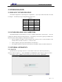
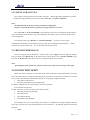
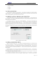
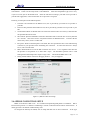
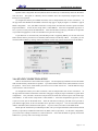
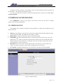
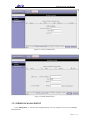
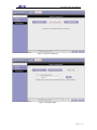
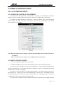
Atrie DB-120 WL User Manual
Atrie DB120-WL Wireless 4-port
Ethernet DSL Gateway/Router
User Manual
( V 1.0 )
Atrie DB-120 WL User Manual
CONTENTS
1 OVERVIEW....................................................................................................................................................... 4
1.1 ABOUT WIRELESS ADSL ..................................................................................................................... 4
1.2 ABOUT ADSL2/2+............................................................................................................................... 4
1.3 FEATURES........................................................................................................................................... 4
2 INTRODUCTION ............................................................................................................................................. 5
2.1 INTERFACE INTRODUCTION .......................................................................................................... 5
2.1.1 INDICATOR AND INTERFACE.................................................................................................. 5
2.1.2 SPLITTER SPEC........................................................................................................................... 5
2.2 HARDWARE CONNECTION ............................................................................................................. 5
2.3 LED STATUS INDICATION................................................................................................................ 6
3 CONFIGURATION........................................................................................................................................... 7
3.1 DEFAULT CONFIGURATION............................................................................................................ 7
3.2 CONFIGURATION OF COMPUTER.................................................................................................. 7
3.3 GENERAL OPERATION ..................................................................................................................... 7
3.3.1 LOG IN.......................................................................................................................................... 7
3.3.2 APPLY AND SAVE ALL............................................................................................................... 8
3.3.3 RESTART WIRELESS AP............................................................................................................ 8
3.4 CONNECTION SETUP........................................................................................................................ 8
3.4.1 NEW CONNECTION ................................................................................................................... 9
3.4.2 BRIDGE GATEWAY PROFILE AND CONNECTION ............................................................... 9
3.4.3 PPPoA CONNECTION SETUP.................................................................................................... 9
3.4.4 PPPoE CONNECTION SETUP .................................................................................................. 10
3.4.5 DHCP CONNECTION SETUP................................................................................................... 12
3.4.6 STATIC CONNECTION SETUP ................................................................................................ 12
3.4.7 CLASSICAL IP OVER ATM (CLIP, DEFINED IN RFC1577) CONNECTION SETUP.......... 13
3.4.8 MODIFY AN EXISTING CONNECTION ................................................................................. 14
3.5 WIRELESS CONFIGURATION ................................................................................................................. 14
3.5.1 WIRELESS SETUP..................................................................................................................... 14
3.5.2 WIRELESS SECURITY ............................................................................................................. 15
3.5.3 WIRELESS MANAGEMENT .................................................................................................... 17
4 OTHER CONFIGURATION ......................................................................................................................... 20
4.1 LAN CONFIGURATION ................................................................................................................... 20
4.1.1 CONFIGUR GATEWAY’S IP ADDRESS .................................................................................. 20
4.1.2 DHCP CONFIGURATION ......................................................................................................... 20
4.2 PASSWORD CONFIGURATION ...................................................................................................... 21
5 TROUBLESHOOTING .................................................................................................................................. 22
5.1 THE GATEWAY IS NOT FUNCTIONAL.......................................................................................... 22
5.2 I CAN’T CONNECT TO THE GATEWAY ........................................................................................ 22
5.3 WAN LED CONTINUES TO BLINK BUT DOES NOT GO SOLID................................................. 22
Page 2 / 25
Atrie DB-120 WL User Manual
5.4 WAN LED IS ALWAYS OFF.............................................................................................................. 23
6 ROUTER TERMS ........................................................................................................................................... 24
ANNEX: SHIPPING LIST ................................................................................................................................ 25
Page 3 / 25
Atrie DB-120 WL User Manual
1 OVERVIEW
1.1 ABOUT WIRELESS ADSL
An ADSL MODEM is a broadband Internet access device, which utilizes the high frequency segment of
the phone line to transmit high-speed data without affecting the voice transmission. The frequency of the
ADSL signal is higher than that of voice, so voice and ADSL signal can coexist in one line by using a splitter to
insulate each from the other. ADSL data transfer adapts the asymmetry model. It supports upload
transmission speed up to 1Mbps and download speed up to 8 Mbps (24Mbps for ADSL2+). ADSL is an ideal
device for broadband access.
But the ADSL users are also limited by the cable and can’t move freely. Wireless ADSL is a new device
that integrates WLAN and ADSL functions. User can slip the leash to visit Internet expediently as long as they
install WLAN card into their computer. The device can be utilized in company, hotel, cafe, airport, station, and
financial institution and home where there are many mobile users and the network infrastructures are difficult to
establish. The wireless ADSL supports 802.11b, 802.11b+ and 802.11g mode with maximum data rate 54Mbps.
1.2 ABOUT ADSL2/2+
Transmission performance of ADSL2 is improved comparing with the first generation of ADSL. These
improvements are mainly concerned with long distance, anti-line-loss, anti-noise, etc. By doubling the
transmission bandwidth, ADSL2+ has implemented a downlink rate as high as 24 Mbps. Therefore, Internet
applications such as synchronous transmission of multi video stream, online games and huge capacity of
downloading files are made possible.
1.3 FEATURES
1.
Support ANSI T1.413 ISSUE 2, ITU G.992.1(G.DMT), ITU G.992.2(G.LITE), ITU G.992.3(ADSL2),
ITU G.992.5(ADSL2+).
2. Support data transportation among ADSL, Ethernet and WLAN
3. Support 802.11b, 802.11b+ and 802.11g mode
4. Web-based configuration and monitoring.
5. Support up to 8 PVCs.
6. Routing function.
7. Support NAT, DHCP.
8. Maximum downstream transmission rates of 8 Mbps (24Mbps for ADSL2+).
9. Maximum upstream transmission rates of 1Mbps.
10. Transmission distance up to 5.5 km.
11. Wireless access distance is more than 100m
Page 4 / 25
Atrie DB-120 WL User Manual
2 INTRODUCTION
2.1 INTERFACE INTRODUCTION
2.1.1 INDICATOR AND INTERFACE
Table 2.1
Item
Indicator
Name
Introduction
POWER
Red, Indicates the status of the power connection.
WAN
Yellow, Shows DSL line status.
PPPoE
Green, Indicates the status of internal PPPoE.
LAN
Green, Indicates the status of Ethernet interface.
LINE
Connected with phone line or "ADSL" port of the splitter.
ETHERNET
To be connected to a PC network card by a straight-through network cable,
also can use a crossover cable to connect to Hub, Switch or Router.
POWER
Power interface, Connect with power adapter.
RST
The RST button will set the Gateway to its factory default setting and
reset the Gateway. You may need to place the Gateway into its factory
defaults if the configuration is changed, you loose the ability to interface to
the Gateway via the web interface, or following a software upgrade, and you
loose the ability to interface to the Gateway. To reset the Gateway, simply
press the reset button for more than 10 seconds. The Gateway will be reset
to its factory defaults and after about 30 seconds the Gateway will become
operational again.
SWITCH
To turn on / off the power.
Interface
2.1.2 SPLITTER SPEC
Table 2.2
Interface
Introduction
LINE
Connected with telephone line.
ADSL
Connect with the LINE port of the Gateway by
telephone line provided.
PHONE
Connect with telephone.
2.2 HARDWARE CONNECTION
Figure 2.1
Page 5 / 25
Atrie DB-120 WL User Manual
Introduction:
1. Use a telephone cord to connect the LINE port of the splitter with the RJ-11 port (the phone jack) on
the wall.
2. Use another telephone cord to connect the ADSL port of the splitter with the LINE port of the
Gateway.
3. Use another telephone cord to connect the telephone set with the PHONE port of the splitter.
4. Connect Ethernet port of the Gateway with 10/100BASE-T port of the computer using the network
cable that comes with the modem.
5. Plug in the power cord, and turn on the power.
If you do not want Internet services and telephone voice services simultaneously, please just connect the
LINE port of the Gateway with the RJ-11 port (the phone jack) on the wall using a telephone cord. In this case,
the splitter is not necessary.
2.3 LED STATUS INDICATION
Table 2.3
Status
ON
Flashing
POWER
Normal Operation
N/A
WAN
DSL line is trained
DSL
training
PPPoE
PPPoE
established
N/A
LAN/WiFi
Green: Ethernet is
connected
Red: Wireless works.
link
Fast Blinking
is
OFF
N/A
Power not applied
DSL is transforming data
DSL line not Connected
N/A
No PPPoE link established
Ethernet or wireless traffic
is flowing
Ethernet and Wireless is not
connected;
Page 6 / 25
Atrie DB-120 WL User Manual
3 CONFIGURATION
3.1 DEFAULT CONFIGURATION
The default configuration is 1483 bridge LLC encapsulation. If you only use this mode, there is no need
to configure. The Gateway has pre-configuration the follow PVCs:
Table 3.1
Name
VPI
VCI
pvc_0_32
0
32
pvc_8_35
8
35
pvc_0_35
0
35
pvc_8_81
8
81
pvc_0_100
0
100
pvc_14_24
14
24
3.2 CONFIGURATION OF COMPUTER
The default IP address for the Gateway is: 192.168.1.1 and the subnet mask is: 255.255.255.0. Users can
configure the Gateway through an Internet Browser. The Gateway can be used as gateway and DNS server
then users need to set the computer’s TCP/IP protocol as follow:
1. Set the computer’s IP address at same segment of the Gateway, such as set the IP address of the
network card to one of the "192.168.1.2" - "192.168.1.254".
2. Set the computer’s gateway the same IP address as the Gateway’s.
3. Set computer’s DNS server the same as the Gateway’s IP address or that of an effective DNS server.
3.3 GENERAL OPERATION
3.3.1 LOG IN
Open the browser; input "http://192.168.1.1" at the address column. Press "Enter" key then the log
interface is shown as Figure 3.1. Input "Username" and "Password" (capital sensitive), then press "Enter".
The default account is "admin" and the default password for this account is "password".
Figure 3.1
Page 7 / 25
Atrie DB-120 WL User Manual
3.3.2 APPLY AND SAVE ALL
Press "Apply" can apply the changes you make on the page. But the apply button temporarily saves that.
To make the changes permanent you need to click the "Save All" in "System Commands".
Notes:
The WEB-UI maybe fresh showly when you submit the configuration.
So please wait a moment and don’t refresh the web page many times in secends.
Press "Save All" in "System Commands" to permanently save the current configuration of the Gateway.
If you do restart the system without saving your configuration, the Gateway will revert back to the previously
saved configuration.
To restart the system, press "Restart" in "System Commands". If you have not saved your
configurations, the Gateway will revert back to the previously saved configuration upon restarting. NOTE:
Connectivity to the unit will be lost. You can reconnect after the unit reboots.
3.3.3 RESTART WIRELESS AP
After you changed wireless parameters in wireless section, press "Apply" button can apply the changes.
Then you should click “Restart AP” on the bottom of the wireless page to enter “System Commands” page.
Until you hit “Restart AP” button the new wireless configuration doesn’t go into effect.
Notes:
After modifying wireless parameters, you must restart wireless AP for wireless changes to take effect .
3.4 CONNECTION SETUP
Before the Gateway will pass any data between the LAN interface(s) and the WAN interface, the WAN
side of the modem must be configured. Depending upon your DSL service provider or your ISP, you will need
some (or all) of the information outlined below before you can properly configure the WAN:
1. Your DSL line VPI and VCI
2. Your DSL encapsulation type and multiplexing
For PPPoA or PPPoE users, you also need these values from your ISP:
Your username and password
For RFC 1483 users, you may need these values from your ISP:
1. Your DSL fixed Internet IP address
2. Your Subnet mask
3. Your Default Gateway
4. Your primary DNS IP address
Since multiple users can use the Gateway, the Gateway can simultaneously support multiple connection
types; hence, the user must set up different profiles for each connection. The Gateway supports the following
protocols:
1. DHCP
Page 8 / 25
Atrie DB-120 WL User Manual
2.
3.
4.
5.
6.
RFC 2364 PPPoA
RFC 2516 PPPoE
Static
Bridged
CLIP
3.4.1 NEW CONNECTION
A new connection is basically a virtual connection. Your Gateway can support up to 8 different (unique)
virtual connections. If you have multiple different virtual connections, you man need to utilize the static and
dynamic routing capabilities of the modem to pass data correctly.
3.4.2 BRIDGE GATEWAY PROFILE AND CONNECTION
A pure bridged connection does not assign and IP address to the WAN interface. NAT and firewall rules
are not enabled. This connection method makes the router act as a hub, and just passes packets across the
WAN interface to the LAN interface.
To configure the Gateway as a bridge, click on "New Connection". At the Type field select Bridge and
the Bridge connection setup page is displayed (Figure 3.2). Give your Bridge connection a unique name; the
name must not have spaces and cannot begin with numbers. In this case the unique name is called bridge1.
Select the encapsulation type (LLC or VC); if you are not sure just use the default mode. Select the VPI and
VCI settings; your DSL service provider or your ISP will supply these; in this case the DSL service provider is
using 0,35.
Figure 3.2 (Bridge Connection Setup)
3.4.3 PPPOA CONNECTION SETUP
PPPoA is also known as RFC 2364. It is a method of encapsulating PPP packets over ATM cells, which
are carried over the DSL line. PPP or Point-to-Point protocol is a method of establishing a network connection
/ session between network hosts. It usually provides a mechanism of authenticating users. LLC and VC are
two different methods of encapsulating the PPP packet. Contact your ISP to make sure which encapsulation is
being supported.
By selecting PPPoA, you are forcing your Gateway to terminate the PPPoA connection. The advantage is
that the PPPoA termination is done within the Gateway and not on your PC; this frees up your PC resources and
allows multiple users to utilize the PPPoA connection.
To configure the Gateway for PPPoA, click on Setup and then click on New Connection. At the Type
field select PPPoA and the PPPoA connection setup page is displayed; Figure 3.3 illustrates a typical PPPoA
Page 9 / 25
Atrie DB-120 WL User Manual
configuration. Give your PPPoA connection a unique name; the name must not have spaces and cannot begin
with numbers. In this case the unique name is called PPPOA1. Select the encapsulation type (LLC or VC);
if you are not sure just use the default mode. Select the VPI and VCI settings; your DSL service provider or
your ISP will supply these; in this case the DSL service provider is using 0,40.
Following is a description of the different options:
1. Username: The username for the PPPoA access; this is provided by your DSL service provider or
your ISP.
2. Password: The password for the PPPoA access; this is provided by your DSL service provider or your
ISP.
3. On-Demand: Enables on-demand mode. The connection will disconnect if no activity is detected after
the specified idle timeout value.
4. Idle Timeout: Specifies that PPPoA connection should disconnect if the link has no activity detected
for n seconds. This field is used in conjunction with the On-Demand feature. To ensure that the
link is always active, enter a 0 in this field.
5. Keep Alive: When on-demand option is not enable, this value specifies the time to wait without being
connected to your provider before terminating the connection. To ensure that the link is always
active, enter a 0 in this field.
6. MRU: Maximum Receive Unit the DSL connection can receive. It is a negotiated value that asks
the provider to send packets of no more than n bytes. The maximum specified value is 1500
although some DSL/ISP providers require a larger value. The minimum MRU value is 128.
7. Debug: Enables PPPoA connection debugging facilities. Only for supporter.
Figure 3.3 (PPPoA Connection Setup)
3.4.4 PPPOE CONNECTION SETUP
PPPoE is also known as RFC 2516. It is a method of encapsulating PPP packets over Ethernet. PPP or
Point-to-Point protocol is a method of establishing a network connection/session between network hosts. It
usually provides a mechanism of authenticating users.
To configure the Gateway for PPPoE, click on Setup and then click on New Connection. At the Type
Page 10 / 25
Atrie DB-120 WL User Manual
field select PPPoE and the PPPoE connection setup page is displayed; Figure 3.4 illustrates a typical PPPoE
configuration. Give your PPPoE connection a unique name; the name must not have spaces and cannot begin
with numbers. In this case the unique name is called PPPOE1. Select the encapsulation type (LLC or VC); if
you are not sure just use the default mode. Select the VPI and VCI settings; your DSL service provider or your
ISP will supply these; in this case the DSL service provider is using 0,30.
Following is a description of the different options:
1. Username: The username for the PPPoE access; this is provided by your DSL service provider or
your ISP.
2. Password: The password for the PPPoE access; this is provided by your DSL service provider or your
ISP.
3. On-Demand: Enables on-demand mode. The connection will disconnect if no activity is detected after
the specified idle timeout value.
4. Idle Timeout: Specifies that PPPoE connection should disconnect if the link has no activity detected
for n seconds. This field is used in conjunction with the On-Demand feature. To ensure that the link
is always active, enter a 0 in this field.
5. Keep Alive: When on-demand option is not enable, this value specifies the time to wait without being
connected to your provider before terminating the connection. To ensure that the link is always active,
enter a 0 in this field.
6. Default Gateway: Specify this connection as the default-route.
7. MRU: Maximum Receive Unit the DSL connection can receive. It is a negotiated value that asks the
provider to send packets of no more than n bytes. The maximum specified value is 1500 although
some DSL/ISP providers require a larger value. The minimum MRU value is 128.
8. Enforce MRU: Check the box if you experience problems accessing the Internet over a PPPoE
connection. This feature will force all TCP traffic to conform with PPP MRU by changing TCP
Maximum Segment Size to PPP MRU.
9. Debug: Enables PPPoE connection debugging facilities. Only for supporter.
Figure 3.4 (PPPoE Connection Setup)
Page 11 / 25
Atrie DB-120 WL User Manual
3.4.5 DHCP CONNECTION SETUP
Dynamic Host Configuration Protocol (DHCP) allows the Gateway to automatically obtain the IP address
from the server. This option is commonly used in situations where IP is dynamically assigned and is not
known prior to assignment.
To configure the Gateway for a DHCP connection, click on Setup and then click on New Connection. At
the Type field select DHCP and the DHCP connection setup page is displayed; Figure 3.5 illustrates a typical
DHCP configuration. Give your DHCP connection a unique name; the name must not have spaces and cannot
begin with numbers. In this case the unique name is called DHCP1. Select the encapsulation type (LLC or
VC); if you are not sure just use the default mode. Select the VPI and VCI settings; your DSL service provider
or your ISP will supply these; in this case the DSL service provider is using 0,35.
If your DSL line is connected and your DSL/IPS provider is supporting DHCP, you can click the renew
button and the Gateway will retrieve an IP address, Subnet mask, and Gateway address. At anytime, you can
renew the DHCP address by clicking on the renew button; in most cases you will never have to use this button.
Figure 3.5 (DHCP Connection Setup)
3.4.6 STATIC CONNECTION SETUP
Static is used whenever a known static IP is assigned. The accompanying information such as the Subnet
mask and the Gateway should also be specified. Up to three Domain Name Server (DNS) addresses can also
be specified. These servers would enable you to have access to other web servers. Valid IP addresses range
is from 0.0.0.0 to 255.255.255.255.
To configure the Gateway for a Static connection, click on Setup and then click on New Connection. At
the Type field select Static and the Static connection setup page is displayed; figure 8 illustrates a typical Static
configuration. Give your Static connection a unique name; the name must not have spaces and cannot begin
with numbers. In this case the unique name is called STATIC1. Select the encapsulation type (LLC or VC);
if you are not sure just use the default mode. Select the VPI and VCI settings; your DSL service provider or
your ISP will supply these; in this case the DSL service provider is using 0,35. You can also enable Network
Address Translation (NAT) and the Firewall options. If you are unsure, leave these in the default mode.
Based upon the information your DSL/ISP provided, enter your assigned IP address, Subnet mask, Default
Gateway (if provided), and Domain Name Services (DNS) values (if provided). For the static configuration,
you can also select a bridge connection or a routed connection. Since static IP address is typically used to host
WEB servers, you may want to use a bridge connection.
Page 12 / 25
Atrie DB-120 WL User Manual
Figure 3.6 (Static IP Connection Setup)
3.4.7 CLASSICAL IP OVER ATM (CLIP, DEFINED IN RFC1577)
CONNECTION SETUP
The Classical IP over ATM (CLIP) support provides the ability to transmit IP packets over an ATM
network, The CLIP support will encapsulate IP in an AAL5 packet data unit (PDU) frame using RFC1577and it
utilizes an ATM aware version of the ARP protocol (ATMARP. The CLIP support only allows for PVC support;
it does not support SVC.
To configure the Gateway for a CLIP connection, click on Setup and then click on New Connection. At
the Type field select CLIP and the CLIP connection setup page is displayed; Figure 3.7 illustrates a typical CLIP
configuration. Give your CLIP connection a unique name; the name must not have spaces and cannot begin
with numbers. In this case the unique name is called CLIP1. Select the VPI and VCI settings; your DSL
service provider or your ISP will supply these; in this case the DSL service provider is using 0,35. You can
also enable Network Address Translation (NAT) and the Firewall options. If you are unsure, leave these in the
default mode.
Figure 3.7 (CLIP Connection Setup)
Page 13 / 25
Atrie DB-120 WL User Manual
3.4.8 MODIFY AN EXISTING CONNECTION
To modify an existing connection, from the Home screen, click setup and then click the connection you
want to modify. The connections are listed as its name.
As a note, if you delete the connection, to make the change permanent you need to click "Save All" in
"System commands".
3.5 WIRELESS CONFIGURATION
Press “WIRELESS” on the top of web pages to enter wireless section. You can select to configure
wireless setup, security and management.
3.5.1 WIRELESS SETUP
Click “Setup” on the left menu to setup basic wireless parameters. In default, check “Enable AP” box to
launch wireless AP.
z
z
z
z
z
SSID (Service Set Identifier): The mobile users cannot access WLAN until setting their SSID as the same
value of the wireless ADSL. The SSID value of the ADSL is “default”
Hidden SSID: If checked, wireless station will no see SSID of the ADSL.
Channel B&G:To denote the different frequency of wireless signals whose value is from 1 to 11. The
default value is”11”. If there are more than one APs located in the same area, each of them must works at
different channels to reduce interference. For Example: Three APs are install in the same place, the AP’s
channel should be 1,6 and 11 respectively.
802.11 Mode: You can select one of “B only”(802.11b only), “B+”(802.11b+), “G only”(802.11g) or
“Mixed”. If “Mixed” selected, the wireless router will adapt itself to wireless station.
User Isolation: If checked, the mobile users can’t see and access each other by network neighbor.
Figure 3.8 (Wireless Setup)
Page 14 / 25
Atrie DB-120 WL User Manual
3.5.2 WIRELESS SECURITY
Press “Security” on the left menu to construct wireless security. You can select to configure WEP
encryption, 802.1x and WPA authentication.
z
Figure 3.9 (Wireless Security)
WEP Encryption
Select “WEP” to enter WEP encryption page. In the page, check “Enable WEP Wireless Security”
box.
Authentication Type: The method of authenticating wireless station. You can select one of
“Open”( Open System ), “Shared”( Shared Key ), “Both”
Cipher: Key length: 64bits, 128bits or 256bits.
Encryption Key 1-4: Up to four keys that are in form of hex digitals could be set. Mobile users can’t
access the AP if they haven’t set the same key as AP. For 64bits, 128bits and 256bits keys, you should
input 10, 26 and 58 hexadecimal digitals respectively. Every two digitals should be comparted with
others by a space character. For example: AA AA AA AA AA for a key length of 64bits.
Page 15 / 25
Atrie DB-120 WL User Manual
Figure 3.10 (WEP encryption)
z
802.1x Authentication
Select “802.1x” to enter 802.1x authentication page.
The 802.1x authentication needs a Radius server in LAN. In this page, you can input Radius server IP
address, port number and secret key.
z
WPA authentication
Select “WPA” to enter WPA authentication page.
For small office and home user, there is no Radius server in LAN. So they can use
WPA-PSK( Pre-Shared Key ) authentication. Method: select “PSK String” and input string key. The
key length should not be more than 63 characters.
Enterprise user has Radius server. They can use 802.1x authentication system. Method: in WPA page,
select “802.1x”, input Radius server IP address, port and secret key.
Page 16 / 25
Atrie DB-120 WL User Manual
Figure 3.11 (802.1x authentication)
Figure 3.12 (WPA authentication)
3.5.3 WIRELESS MANAGEMENT
Click “Management” to enter wireless management page. You can configure Access List and Multiple
SSID functions.
Page 17 / 25
Atrie DB-120 WL User Manual
Access List
In fact, the Access List function is just like MAC address filtering and selected to permit or forbid
access of wireless station with specified MAC address.
Method: click “Access List” button, check “Enable Access List” box and select “Allow” or “Ban”,
then input MAC address.
Note: MAC address should be split by character ‘-‘
z
Figure 3.13(Access List)
z
Associated Stations
In the page, you can see information about associated wireless stations to the AP.
z
Multiple SSID
The wireless ADSL supports configuration of multiple SSIDs. Wireless station can use one to access
the AP.
Note: The Multiple SSID support will be disabled if wireless security enabled.
Page 18 / 25
Atrie DB-120 WL User Manual
Figure 3.14(Associated Stations)
Figure 3.15(Multiple SSID)
Page 19 / 25
Atrie DB-120 WL User Manual
4 OTHER CONFIGURATION
4.1 LAN CONFIGURATION
4.1.1 CONFIGUR GATEWAY’S IP ADDRESS
As a network device, the Gateway has its own IP address. The factory sets the MODEM, at a default IP
address of 192.168.1.1 and subnet mask of 255.255.255.0. The user can configure they in "LAN Setup".
For example, to change IP address to "10.10.10.10". Click "LAN Setup", choice "Use the following
Static IP address", then input "10.10.10.10" in "IP address" and "255.0.0.0" in "subnet mask". The result is
shown as Figure4.1, press "Apply".
Figure 4.1
Notes: When the IP address have be changed, it will take effect immediately. Then you maybe cannot access
the WEB-UI.
Please wait about 30 seconds, and then access the WEB-UI by the new IP address.
4.1.2 DHCP CONFIGURATION
The user can configure the DHCP mode in "LAN Setup".
1.
To Enable the DCHP Server mode, choice "Enable DHCP Server" and fill in the following textbox.
The "Start IP" is where the DHCP server starts issuing IP addresses. This value must be greater than the
Gateway’s IP address value. For example if the Gateways IP address is 192.168.1.1 (default) than the starting
IP address must be 192.168.1.2 (or higher).
The "End IP" is where the DHCP server stops issuing IP addresses. The ending address cannot exceed a
subnet limit of 254. Hence the max value for our default Gateway is 192.168.1.254. If the DHCP server runs
out of DHCP addresses, users will not get access to network resources. If this happens you can increase the
Ending IP address (to the limit of 255) or reduce the lease time.
The "Lease Time" is the amount of time a network user will be allowed connection to the Router with their
Page 20 / 25
Atrie DB-120 WL User Manual
current dynamic IP address.
hours).
The amount of time is in units of minutes; the default value is 3600 minutes (60
Note: If you change the start or end values, make sure the values are still within the same subnet as the
Gateways IP address. In other words, if the Gateway’s IP address is 192.168.1.1 (default) and you change
the DHCP start/end IP addresses to be 192.128.1.2/192.128.1.100, you will not be able to communicate to
the Gateway if your PC has DHCP enabled.
2.
To Enable the DHCP Relay mode, choice "Enable DHCP Relay" and input the IP of DHCP Server.
When the Gateway is configured as DHCP relay, it is responsible for forwarding the requests and
responses negotiating between the DHCP clients and the server.
3.
To Disable the DCHP mode, choice "Sever and Relay Off".
By turning off the DHCP server and relay the network administrator must carefully configure the IP
address, Subnet mask and DNS settings of every computer on your network. Do not assign the same IP address
to more than one computer and your Gateway must be on the same subnet as all the other computers.
4.2 PASSWORD CONFIGURATION
When logging in the WEB-UI of the Gateway, the system requires the username and password to validate
access permission. The default account is "admin" and the default password for this account is "password".
The user names are permanent. But the password can be changed in the "User Management".
Attention: Please remember the password after change otherwise you will not be able to change
configuration after saving.
It will log out automatically, if the user doesn’t do any thing after logging in the Gateway for sometime.
The "Idle Timeout" can be configured in "User Management".
Page 21 / 25
Atrie DB-120 WL User Manual
5 TROUBLESHOOTING
Below is a list of commonly asked questions.
issues to see if they help solve your problem.
Before calling technical support, please look through these
5.1 THE GATEWAY IS NOT FUNCTIONAL
1.
2.
3.
4.
5.
6.
Check that the POWER LED is ON.
Check that the network cables are installed correctly and the LAN LED is ON.
Check that the WAN LED is ON.
Check the settings on your PC.
Check the Gateway’s settings.
From your PC, can you PING the Gateway? Assuming that the Gateway has DHCP enabled and your
PC is on the same subnet as the Gateway, you should be able to PING the Gateway.
7. Can you PING the WAN? Your ISP should have provided the IP address of their server. If you can
PING the Gateway and your protocols are configured correctly, you should be able to ping the ISPs
network. If you cannot PING the ISPs network, make sure your using the correct protocols with the
correct VPI/VCI values.
8. Make sure NAT is enabled for your connection. If NAT is disabled you the Gateway will not route
frames correctly.
5.2 I CAN’T CONNECT TO THE GATEWAY
1. Check that the POWER LED is ON.
2. Check that the network cables are installed correctly and the LAN LED is ON.
3. Make sure that your PC and the Gateway is on the same network segment. The Gateway’s default IP
address is 192.168.1.1. If you are running a Windows based PC, you can open a DOS window and
type IPCONFIG; make sure that the network adapter that is connected to the Gateway is within the
same 192.168.1.x subnet.
4. Also, your PC’s Subnet mask should match the Gateway’s subnet mask. The gateway has a default
subnet mask of 255.255.255.0.
5. If this still does not work, press the reset button for 10 seconds. This will place the gateway into its
factory default state. Go through the above procedures again.
6. Make sure NAT is enabled for your connection. If NAT is disabled your the gateway will not route
frames correctly.
5.3 WAN LED CONTINUES TO BLINK BUT DOES NOT GO
SOLID
This means that the DSL line is trying to train but for some reason it cannot establish a valid connection.
The main cause of this is that you are too far away from the central office. Contact your DSL service provider
for further assistance.
Page 22 / 25
Atrie DB-120 WL User Manual
5.4 WAN LED IS ALWAYS OFF
1. Make sure you have DSL service. You should get some kind of information from your ISP, which
states that DSL service is installed. You can usually tell if the service is installed by listening to the
phone line; you will hear some high-pitched noise. If you do not hear high-pitched noise, contact your
ISP.
2. Verify that the phone line is connected directly to the wall and to the line input on the Gateway. If the
phone line is connected to the phone side of the Gateway or you have a splitter installed on the phone
line, the DSL light will not come on.
Page 23 / 25
Atrie DB-120 WL User Manual
6 ROUTER TERMS
What is a firewall?
A firewall is protection between the Internet and your local network. It acts similarly to the firewall in
your car, protecting the interior of the car from the engine. Your car's firewall has very small opening that
allow desired connections from the engine into the cabin (gas pedal connection, etc), but if something happens
to your engine, you are protected.
The firewall in the router is very similar. Only the desired connections that you allow are passed through
the firewall. These connections are normally originating from the local network; such as web browsing,
checking your email, downloading a file, and playing a game. However, in some cases, you can allow
incoming connections so that you can run programs like a web server.
What is NAT?
NAT stands for Network Address Translation. Another name for it is Connection Sharing. What does this
mean? Your ISP provides you with a single network address for you to access the Internet through. However,
you may have several machines on your local network that want to access the Internet at the same time. The
router provides NAT functionality that converts your local network addresses to the single network address
provided by your ISP. It keeps track of all these connections and makes sure that the correct information gets to
the correct local machine.
Occasionally, there are certain programs that don't work well through NAT. Some games, and some
specialty applications have a bit of trouble. The router contains special functionality to handle the vast
majority of these troublesome programs and games. NAT does cause problems when you want to run a
SERVER though.
What is a gateway?
The Internet is so large that a single network cannot handle all of the traffic and still deliver a reasonable
level of service. To overcome this limitation, the network is broken down into smaller segments or subnets
that can deliver good performance for the stations attached to that segment. This segmentation solves the
problem of supporting a large number of stations, but introduces the problem of getting traffic from one subnet
to another.
To accomplish this, devices called routers or gateways are placed between segments. If a machine wishes
to contact another device on the same segment, it transmits to that station directly using a simple discovery
technique. If the target station does not exist on the same segment as the source station, then the source
actually has no idea how to get to the target.
One of the configuration parameters transmitted to each network device is its default gateway. This
address is configured by the network administrators and it informs each personal computer or other network
device where to send data if the target station does not reside on the same subnet as the source. If your
machine can reach all stations on the same subnet (usually a building or a sector within a building), but cannot
communicate outside of this area, it is usually because of an incorrectly configured default gateway.
Page 24 / 25
Atrie DB-120 WL User Manual
ANNEX: SHIPPING LIST
Item
Quantity
ADSL MODEM
1
Splitter
1
User Manual
1
Power Supply
1
Cable Cat5 RJ45
1
Telephone Line
2
Warranty Certificate
1
Atrie Technology Pvt. Ltd.
Corporate office: Atrie House, # 591,3rd Block, Koramangala, Bangalore -560 034 India
Registered office: #B-121,Ground Floor ,Kalkaji, New Delhi – 110019
Regional office (West): #C/312,3rd Floor, Gokul Arcade, Vile Parle(E) Subhash Road,Mumbai - 400057
Web: http://www.atrieindia.com
Email: [email protected]
Page 25 / 25