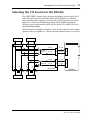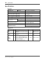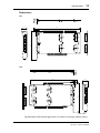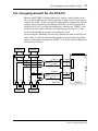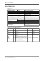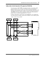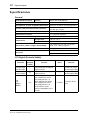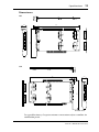
1
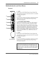
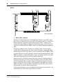
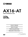
AX16-AT
AUDIO EXPANSION CARD
Owner’s Manual
Mode d’emploi
Bedienungsanleitung
Manual de instrucciones
YAMAHA CORPORATION
M
Pro Audio Division, #18/3
P.O. Box 3, Hamamatsu, 430-8651, Japan
COMPLIANCE INFORMATION STATEMENT
(DECLARATION OF CONFORMITY PROCEDURE)
Responsible Party:
Address:
Telephone:
FAX:
Type of Equipment:
Model Name:
YAMAHA CORPORATION OF AMERICA
6600 Orangethorpe Avenue, Buena Park, Calif. 90620 U.S.A.
1-714-522-9011
1-714-739-2680
AUDIO EXPANSION CARD
AX16-AT
This device complies with Part 15 of the FCC Rules.
Operation is subject to the following conditions:
1) this device may not cause harmful interference, and
2) this device must accept any interference received including interference that may cause undesired operation.
FCC INFORMATION (U.S.A.)
1. IMPORTANT NOTICE: DO NOT MODIFY THIS UNIT! This product, when installed as indicated in the instructions contained in this manual, meets FCC
requirements. Modifications not expressly approved by Yamaha may void your authority, granted by the FCC, to use the product.
2. IMPORTANT: When connecting this product to accessories and/or another product use only high quality shielded cables. Cable/s supplied with this product MUST
be used. Follow all installation instructions. Failure to follow instructions could void your FCC authorization to use this product in the USA.
3. NOTE: This product has been tested and found to comply with the requirements listed in FCC Regulations, Part 15 for Class “B” digital devices. Compliance with
these requirements provides a reasonable level of assurance that your use of this product in a residential environment will not result in harmful interference with
other electronic devices. This equipment generates/uses radio frequencies and, if not installed and used according to the instructions found in the users manual, may
cause interference harmful to the operation of other electronic devices. Compliance with FCC regulations does not guarantee that interference will not occur in all
installations. If this product is found to be the source of interference, which can be determined by turning the unit “OFF” and “ON”, please try to eliminate the
problem by using one of the following measures: Relocate either this product or the device that is being affected by the interference. Utilize power outlets that are on
different branch (circuit breaker or fuse) circuits or install AC line filter/s. In the case of radio or TV interference, relocate/reorient the antenna. If the antenna lead-in
is 300 ohm ribbon lead, change the lead-in to coaxial type cable. If these corrective measures do not produce satisfactory results, please contact the local retailer
authorized to distribute this type of product. If you can not locate the appropriate retailer, please contact Yamaha Corporation of America, Electronic Service
Division, 6600 Orangethorpe Ave, Buena Park, CA 90620
The above statements apply ONLY to those products distributed by Yamaha Corporation of America or its subsidiaries.
Contents
Introduction . . . . . . . . . . . . . . . . . . . . . . . . . . . . . . . . . 4
System Requirements . . . . . . . . . . . . . . . . . . . . . . . . . . . . . . 4
PCI or ISA? . . . . . . . . . . . . . . . . . . . . . . . . . . . . . . . . . . . . . . . 4
Controls & Connections . . . . . . . . . . . . . . . . . . . . . . . . 5
Rear . . . . . . . . . . . . . . . . . . . . . . . . . . . . . . . . . . . . . . . . . . . . . 5
Internal . . . . . . . . . . . . . . . . . . . . . . . . . . . . . . . . . . . . . . . . . . 6
System Hookup Overview . . . . . . . . . . . . . . . . . . . . . . . 8
Installing the AX16-AT . . . . . . . . . . . . . . . . . . . . . . . . . 9
Fitting the ISA-bus Mounting Bracket . . . . . . . . . . . . . . . . 10
Selecting the I/O Source for the DS2416 . . . . . . . . . . . 11
Specifications . . . . . . . . . . . . . . . . . . . . . . . . . . . . . . . . 12
Dimensions . . . . . . . . . . . . . . . . . . . . . . . . . . . . . . . . . . . . . . 13
3
Important Notices
•
Do not place the AX16-AT in an area subject to excessive heat, direct sunlight, excessive humidity, or dust.
•
Keep the AX16-AT inside its antistatic bag until you are ready to install it.
•
To prevent handling damage, hold the AX16-AT by the edges or bracket.
•
If you accidentally touch the card edge connections, remove any fingerprints using a dry tissue.
•
Do not place objects on top of the AX16-AT, and do not put it down in a
place where other objects are likely to be placed on top of it.
•
Before removing your computer’s cover, turn it off and remove the power
cord.
•
To prevent static electricity damage, touch a grounded metal part of your
computer, such as the power supply case, before handling the AX16-AT.
Packing List
•
AX16-AT Audio Expansion Card
•
DS2416 20-pin connection cable x2
•
ISA-bus mounting bracket
•
This manual
Trademarks
ADAT MultiChannel Optical Digital Interface is a trademark and ADAT and
Alesis are registered trademarks of Alesis Corporation. Yamaha is a trademark
of Yamaha Corporation. All other trademarks are the property of their respective holders and are hereby acknowledged.
Copyright
No part of the AX16-AT Owner’s Manual may be reproduced or distributed in
any form or by any means without the prior written authorization of Yamaha
Corporation, Inc.
© 1998 Yamaha Corporation. All rights reserved.
Keep this manual safe for future reference!
AX16-AT—Owner’s Manual
4
Introduction
Introduction
Thank you for purchasing the Yamaha AX16-AT Audio Expansion Card. The
AX16-AT is an ADAT format digital interface card for the Yamaha DS2416
Digital Mixing Card. Two ADAT MultiChannel Optical Digital inputs and
two outputs mean that up to 16 channels of ADAT format digital audio can be
transferred simultaneously between the DS2416 and an ADAT multitrack
recorder, or other ADAT-compatible device, such as a Yamaha 02R, 03D, or
01V digital mixing console with an ADAT I/O card installed.
System Requirements
•
DS2416-compatible computer with a free PCI or ISA-bus slot
•
Yamaha DS2416 Digital Mixing Card
•
DS2416-compatible audio software
PCI or ISA?
The AX16-AT is set for installation in a PCI-bus slot, but can also be installed
in an ISA slot simply by swapping the supplied mounting bracket. Since
DS2416-compatible Apple Power Macintosh computers do not support ISA
bus, the AX16-AT must be used in a PCI slot with Power Macs. On
DS2416-compatible Windows computers, however, the AX16-AT can be used
in either a PCI or ISA-bus slot, which means that even if all your PCI slots are
taken and the only free slots are ISA, you can still install the AX16-AT.
Important: If you are using the DS2416 and AX16-AT in a Windows 95 or
Windows 98 computer, be sure to use DS2416 driver version V103 or later.
The latest driver software is available for free download from the Yamaha
Professional Audio Web site.
<http://www.yamaha.co.jp/product/proaudio/homeenglish/>
DS2416 driver version V102 or earlier does not support the AX16-AT
ADAT/THRU switch. However, it can be made to recognize the switch by
relaunching the DS2416-supporting audio software.
Important: When the DS2416’s internal Vari Pitch mode is used, the wordclock, or sampling rate changes accordingly and some devices connected to
the AX16-AT for use as wordclock slaves may not be able to synchronize correctly. However, they may synchronize correctly at certain settings (resultant
sampling rates), but not others.
AX16-AT—Owner’s Manual
Controls & Connections
5
Controls & Connections
Rear
A A IN
A
IN
1
OUT
2
ADAT
3
THRU
4
IN
5
Signals arriving at this ADAT MultiChannel Optical Digital
input are fed through to the IO-A connector on this card.
B A OUT
Signals from the IO-A outputs on the DS2416 are output via
this ADAT MultiChannel Optical Digital output.
C A & B ADAT/THRU switches
These switches are used to select the input and output signals for the IO-A and IO-B connectors on this card. IO-A
and IO-B can be set individually. In the ADAT position, the
DS2416 receives and transmits signals via the A or B IN and
OUT connectors on this card. In the THRU position, the
DS2416 receives and transmits signals via the THRU A or B
connectors on this card.
D B IN
OUT
B
Signals arriving at this ADAT MultiChannel Optical Digital
input are fed through to the IO-B connector on this card.
E B OUT
Signals from the IO-B outputs on the DS2416 are output via
this ADAT MultiChannel Optical Digital output.
(PCI mounting)
Note: Be aware that if the body of the plugs on your optical
cables is too large to pass easily through the expansion-slot
holes in the rear of your computer, the plugs may not plug
into the ADAT jacks properly and may come lose.
AX16-AT—Owner’s Manual
6
Controls & Connections
Internal
23
45
[ THROUGH IO-A ]
THRU-A
A
IO-A
A
A
HALF
FULL
[ THROUGH IO-B ]
THRU-B
B
B
B
B
[ THROUGH IO-B ]
IO-B
B
B
OFF
A
[ THROUGH IO-A ]
A
A
1
(PCI mounting)
A HALF/FULL switches
These switches are used to configure wordclock operation when the DS2416
is used as a wordclock slave and receives its wordclock from the AX16-AT. IOA and IO-B can be set individually. In the FULL position, the DS2416 derives
its wordclock from the source selected using the ADAT/THRU switches.
Normally, these switches should be set to HALF, the default setting, in which
case the DS2416’s wordclock source is always an ADAT IN connector regardless of the ADAT/THRU switch settings. This is convenient when switching
between the ADAT and THRU (AX44 or other device) connectors, because
you don’t have to change the wordclock settings.
When an external device connected to the A IN connector is used as the
wordclock master, that device must be turned on and configured correctly for
wordclock master operation. If, for some reason, the external wordclock is
lost, the THRU connectors are checked for a usable wordclock, and if one is
not found there either, the DS2416 stops functioning.
(To use an external device as the wordclock master, you must connect it to the
A IN connector.)
B IO-A connector
This connector connects to the IO-A connector on the DS2416 using the supplied 20-pin connection cable.
AX16-AT—Owner’s Manual
Controls & Connections
7
C IO-B connector
This connector connects to the IO-B connector on the DS2416 using the supplied 20-pin connection cable.
D THRU-A connector
This connector connects to the first AX44 Audio Expansion Unit using the
20-pin connection cable supplied with the AX44.
E THRU-B connector
This connector connects to the second AX44 Audio Expansion Unit using the
20-pin connection cable supplied with the AX44.
AX16-AT—Owner’s Manual
8
System Hookup Overview
System Hookup Overview
The following diagram shows how the AX16-AT connects to the DS2416 and
AX44s. Also shown are two digital multitrack recorders with ADAT format
inputs and outputs for up to 16 channels of digital audio transfer between
them and the DS2416.
IO-B
SI
I
O
SO
IO-A
IO-A
A B
IO-B
DS2416
A
A
AX44-A
A
[ THROUGH IO-A ]
THRU-A
INPUT
1
OUTPUT
1
–10dBV –50dBV
2
LINE MIC
3
LINE MIC
2
3
4
4
AX44
THRU-B
B
[ THROUGH IO-B ]
IO-B
B
B
B
IO-B
IN
OUT
–10dBV –50dBV
[ THROUGH IO-B ]
B
B
OFF
A
A
HALF
POWER
AX16-AT
ADAT-B
A
IO-A
FULL
IN
OUT
[ THROUGH IO-A ]
IO-A
THRU-A
–10dBV –50dBV
ADAT-A
THRU-B
INPUT
1
OUTPUT
1
–10dBV –50dBV
2
LINE MIC
2
3
LINE MIC
3
4
4
POWER
AX44
AX44-B
ADAT-B
ADAT-A
When using an ADAT, set the corresponding ADAT/THRU switch (A or B) to
ADAT. To use an AX44, set the switch to THRU.
In the system shown here, the DS2416, ADAT-A, or ADAT-B could be used as
the wordclock master. (Supporting software is required to set the wordclock.)
If an ADAT recorder is used as the wordclock master, turn on the ADAT first,
set its wordclock, and then set the DS2416 wordclock.
AX16-AT—Owner’s Manual
Installing the AX16-AT
9
Installing the AX16-AT
The AX16-AT installs into a single PCI or ISA expansion slot and requires no
special jumper settings or interrupt settings. If you are installing in an ISA
slot, see “Fitting the ISA-bus Mounting Bracket” on page 10 before continuing with this procedure.
See your computer’s manual for full details on installing cards.
1 Turn off the computer and disconnect the power cord.
2 Remove the computer’s cover.
3 Choose an empty slot for the AX16-AT, and remove the expan-
sion-slot cover.
To prevent static electricity from damaging the AX16-AT, touch a grounded
metal part of your computer, such as the power supply case, before handling
it.
4 Carefully align and insert the AX16-AT into the slot.
A
THRU-A
[ THROUGH IO-A ]
A
A
HALF
OFF
THRU-B
B
B
[ THROUGH IO-B ]
IO-B
B
OFF
PCI
FULL
A
IO-A
A
ISA
5 If the expansion-slot cover was held in place by a screw, secure the
AX16-AT using the same screw.
Important: Tighten the expansion-slot fixing screw so that the AX16-AT cannot jiggle about in the slot.
AX16-AT—Owner’s Manual
10
Installing the AX16-AT
6 Connect the AX16-AT IO-A connector to the DS2416 IO-A connec-
tor using the supplied 20-pin cable (connect the end with the ferrite core to the DS2416).
7 Connect the AX16-AT IO-B connector to the DS2416 IO-B connec-
tor using the supplied 20-pin cable (connect the end with the ferrite core to the DS2416).
8 If you are using an AX44, connect the AX16-AT THRU-A connector
to the first AX44 using the 20-pin cable supplied with the AX44.
9 If you are using a second AX44, connect the AX16-AT THRU-B con-
nector to the second AX44 using the 20-pin cable supplied with
the AX44.
10 Replace the computer’s cover.
11 Connect your ADAT multitrack recorder, or other ADAT-compatible
device, such as a Yamaha 02R, 03D, or 01V digital mixing console
with an ADAT I/O card installed, to the A or B IN/OUT connectors
on the rear of the AX16-AT using EIAJ fiber optical cables.
Fitting the ISA-bus Mounting Bracket
Before installing the AX16-AT into an ISA-bus slot, you must replace the
PCI-bus mounting bracket with the ISA-bus mounting bracket.
To prevent static electricity from damaging the AX16-AT, touch a grounded
metal part of your computer, such as the power supply case, before handling
it.
1 Remove the two fixing screws that secure the PCI-bus mounting
bracket to the AX16-AT card and carefully remove the mounting
bracket.
2 Carefully fit the ISA-bus mounting bracket and secure using the
two screws removed previously.
AX16-AT—Owner’s Manual
Selecting the I/O Source for the DS2416
11
Selecting the I/O Source for the DS2416
The ADAT/THRU switches select the input and output sources for the IO-A
and IO-B connectors on the DS2416. In the ADAT position, the DS2416
receives and transmits signals via the ADAT IN and OUT connectors on the
AX16-AT, as shown in the following diagram. In the THRU position, the
DS2416 receives and transmits signals via the AX44s. IO-A and IO-B can be
switched independently.
The lines from the DS2416 are labeled “4 or 8” because they carry four audio
channel when set to THRU (i.e., AX44) and eight channels when set to ADAT.
AX44-A
4
4
4
4
4
4 or 8
ADAT/
THRU-A
4 or 8
4 or 8
4 or 8
8
8
8
4 or 8
IN
ADAT-A
OUT
IN
4 or 8
8
AX16-AT
A
4 or 8
IO-B
ADAT/
THRU-B
4 or 8
IO-A
4
4
THRU-B
IO-B
THRU-A
IO-A
4
AX44-B
B
DS2416
OUT
ADAT-B
AX16-AT—Owner’s Manual
12
Specifications
Specifications
General
Sampling rate
External
40.013 kHz to 50.880 kHz
ADAT/THRU switches
DS2416 I/O source selection
WORDCLOCK HALF/FULL switches
Wordclock source select
PCI-bus (for power supply only)
PCI Raw Variable Height Short Card
(5 V, 32-bit)
ISA-bus (for power supply only)
ISA card (5 V, 8-bit)
Power supply
+5 V (250 mA max)
Maximum power consumption
1.25 W
Temperature
Operating
+10˚C to +35˚C
Storage
–20˚C to +60˚C
Dimensions (H x L x D)
125.9 (ISA 127.7) x 188 x 21.6 mm
(4.95 x 7.4 x 0.85 inch)
Weight
120 g (4.2 oz)
20-pin cable x2
Supplied accessories
ISA-bus mounting bracket
Digital I/O
Connection
I/O
Format
Level
A IN
B IN
I
ADAT MultiChannel Optical Digital
Interface
—
EIAJ fiber optical
jack
A OUT
B OUT
O
ADAT MultiChannel Optical Digital
Interface
—
EIAJ fiber optical
jack
IO-A
IO-B
THRU-A
THRU-B
AX16-AT—Owner’s Manual
4CH or 8CH digital audio inputs
(2CH or 4CH line, MSB first x2)
I/O 4CH or 8CH digital audio outputs 5 V CMOS
(2CH or 4CH line, MSB first x2)
32-bit max/channel
DS2416 compatible format
Connector
20-pin connector
13
Specifications
Dimensions
PCI
21.6
188
A
A
3.1
A
[ THROUGH IO-A ]
A
A
A
HALF
B
B
OFF
ADAT
FULL
OUT
[ THROUGH IO-A ]
IO-A
THRU-A
A
IN
THRU-B
B
[ THROUGH IO-B ]
B
IN
[ THROUGH IO-B ]
IO-B
125.9
THRU
OUT
B
B
B
ISA
188
21.6
3.1
B
B
B
OUT
B
[ THROUGH IO-B ]
B
IO-B
THRU-B
[ THROUGH IO-B ]
IN
B
B
THRU
OFF
127.7
A
HALF
FULL
A
ADAT
A
[ THROUGH IO-A ]
A
IO-A
THRU-A
[ THROUGH IO-A ]
OUT
IN
A
A
A
Unit: mm
Specifications and external appearance are subject to change without notice.
AX16-AT—Owner’s Manual
CARTE D’EXPANSION AUDIO
Mode d’emploi
Français
AX16-AT
2
Sommaire
Introduction . . . . . . . . . . . . . . . . . . . . . . . . . . . . . . . . . 4
Système requis . . . . . . . . . . . . . . . . . . . . . . . . . . . . . . . . . . . . 4
PCI ou ISA? . . . . . . . . . . . . . . . . . . . . . . . . . . . . . . . . . . . . . . . 4
Commandes et connexions . . . . . . . . . . . . . . . . . . . . . 5
A l’arrière . . . . . . . . . . . . . . . . . . . . . . . . . . . . . . . . . . . . . . . . 5
A l’intérieur . . . . . . . . . . . . . . . . . . . . . . . . . . . . . . . . . . . . . . . 6
Vue globale des connexions du système . . . . . . . . . . . 8
Installation de l’AX16-AT . . . . . . . . . . . . . . . . . . . . . . . 9
Adaptation de la fixation du bus ISA . . . . . . . . . . . . . . . . . 10
Sélection de la source I/O pour la DS2416 . . . . . . . . . . 11
Fiche technique . . . . . . . . . . . . . . . . . . . . . . . . . . . . . . . 12
Dimensions . . . . . . . . . . . . . . . . . . . . . . . . . . . . . . . . . . . . . 13
AX16-AT—Mode d’emploi
3
Remarques importantes
•
•
•
•
•
•
•
Evitez de placer l’AX16-AT dans des endroits particulièrement chauds,
humides, poussiéreux ou en plein soleil.
Gardez l’AX16-AT dans son sac antistatique jusqu’à ce que vous soyez
prêt à l’installer.
Pour éviter tout dommage durant l’installation, tenez l’AX16-AT par les
bords ou la fixation.
Si vous touchez accidentellement le circuit imprimé au bord de la carte,
enlevez toute empreinte digitale avec un mouchoir sec.
Ne placez aucun objet sur l’AX16-AT et évitez de la déposer à un endroit
où des objets risquent d’être placés sur elle.
Avant d’ouvrir le boîtier de l’ordinateur, mettez-le hors tension et
débranchez le cordon d’alimentation.
Pour éviter tout endommagement par électricité statique, prenez en
main un objet métallique mis à la masse comme le boîtier d’alimentation
de votre ordinateur, par exemple, pour vous décharger de toute électricité
statique.
Contenu de l’emballage
•
•
•
•
Carte d’expansion audio AX16-AT
Câble de connexion à 20 broches DS2416 x2
Fixation pour bus ISA
Ce mode d’emploi
Marques commerciales
ADAT MultiChannel Optical Digital Interface est une marque commerciale et
ADAT ainsi qu’Alesis sont des marques déposées d’Alesis Corporation.
Yamaha est une marque déposée de Yamaha Corporation. Toutes les autres
marques appartiennent à leurs détenteurs respectifs et sont explicitement
reconnues.
Copyright
Ce mode d’emploi de l’AX16-AT ne peut être copié ou distribué sous quelque
forme ou par quelque moyen que ce soit sans l’autorisation écrite préalable de
Yamaha Corporation, Inc.
© 1998 Yamaha Corporation. Tous droits réservés.
Veuillez conserver ce manuel dans un lieu sûr pour toute référence ultérieure!
AX16-AT—Mode d’emploi
4
Introduction
Introduction
Nous vous remercions d’avoir opté pour la carte d’expansion audio AX16-AT
de Yamaha. L’AX16-AT est une interface numérique de format ADAT pour la
carte de mélangeur numérique DS2416 de Yamaha. Avec ses deux entrées et
sorties ADAT MultiChannel Optical Digital, il est possible de transférer des
données audio numériques de format ADAT sur 16 canaux entre la DS2416 et
un enregistreur multipiste ADAT ou tout autre appareil ADAT tel qu’une console de mixage 02R, 03D ou 01V de Yamaha, dotée d’une carte ADAT I/O.
Système requis
•
•
•
Ordinateur compatible avec la DS2416 disposant d’un bus PCI ou ISA
libre.
Carte de mélangeur numérique Yamaha DS2416
Logiciel audio compatible avec la DS2416
PCI ou ISA?
L’AX16-AT a été conçue pour une installation dans un connecteur PCI mais
peut également être placée dans un connecteur ISA. Il suffit d’échanger les
fixations et d’utiliser la fixation ISA prévue à cet effet. Comme les ordinateurs
Apple Macintosh compatibles avec la DS2416 ne comportent pas de bus ISA,
l’AX16-AT doit donc impérativement être installée dans un emplacement PCI
sur les Power Macs. Si vous vous servez d’un ordinateur Windows compatible
avec la DS2416, vous avez le choix entre un connecteur PCI ou ISA. Si tous les
bus PCI sont occupés, vous pouvez toujours installer l’AX16-AT pour autant
qu’il vous reste un bus ISA de libre.
Important: Si vous utilisez la DS2416 et l’AX16-AT sur un ordinateur tournant sous Windows 95 ou 98, veillez à vous servir de la version V103 ou
ultérieure du pilote de la DS2416. La version la plus récente du pilote est
téléchargeable gratuitement à partir du site Yamaha Professional Audio.
<http://www.yamaha.co.jp/product/proaudio/homeenglish/>
La version V102, voire une version antérieure du pilote pour la DS2416, ne
permet pas l’utilisation du commutateur ADAT/THRU. Il n’empêche que vous
pouvez faire le nécessaire pour qu’il le reconnaisse en relançant le logiciel
audio compatible avec la DS2416.
Important: Lors de l’utilisation du mode Vari Pitch de la DS2416, la
fréquence d’échantillonnage ainsi que les données Wordclock changent
aussi. Dans ce cas, certains appareils connectés à l’AX16-AT (en tant
qu’esclaves Wordclock) risquent de ne plus pouvoir être synchronisés. Certains réglages (produisant des fréquences d’échantillonnage reconnues) peuvent cependant donner le résultat escompté.
AX16-AT—Mode d’emploi
Commandes et connexions
5
Commandes et connexions
A l’arrière
A
IN
A A IN
Les signaux arrivant à cette entrée ADAT MultiChannel
Optical Digital sont envoyés au connecteur IO-A de cette
carte.
B A OUT
1
OUT
2
ADAT
3
THRU
4
IN
5
OUT
B
Les signaux venant des sorties IO de la carte DS2416 sont
produits via cette sortie ADAT MultiChannel Optical Digital.
C Commutateurs A & B ADAT/THRU
Ces commutateurs vous permettent de sélectionner les
signaux d’entrée et de sortie pour les connecteurs IO-A et
IO-B de cette carte. Ce réglage peut être effectué indépendamment pour IO-A et IO-B. Si vous optez pour “ADAT”,
l’entrée et la sortie correspondante (A ou B) de la DS2416 est
reliée aux bornes A IN/OUT ou B IN/OUT. L’option
“THRU” signifie que la DS2416 est reliée au connecteur
THRU A ou THRU B de l’AX16-AT.
D B IN
Les signaux arrivant à cette entrée ADAT MultiChannel
Optical Digital sont envoyés au connecteur IO-B de cette
carte.
E B OUT
(Montage PCI)
Les signaux venant des sorties IO de la carte DS2416 sont
produits via cette sortie ADAT MultiChannel Optical Digital.
Remarque: Si les prises des câbles optiques utilisés sont trop
larges en n’entrent dès lors pas tout à fait dans la fente
d’extension en face arrière de votre ordinateur, il est fort
probable que la connexion aux bornes ADAT ne se fasse pas
ou pas entièrement.
AX16-AT—Mode d’emploi
6
Commandes et connexions
A l’intérieur
23
45
[ THROUGH IO-A ]
THRU-A
A
IO-A
A
A
HALF
FULL
[ THROUGH IO-B ]
THRU-B
B
B
B
B
[ THROUGH IO-B ]
IO-B
B
B
OFF
A
[ THROUGH IO-A ]
A
A
1
(Montage PCI)
A Commutateurs HALF/FULL
Ces commutateurs permettent de régler des paramètres Wordclock lorsque la
DS2416 est asservie à l’horloge Wordclock de l’AX16-AT. IO-A et IO-B peuvent être réglés séparément. En position “FULL”, la DS2416 tire son signal
Wordclock de la source sélectionnée avec les commutateurs ADAT/THRU.
Normalement, ces commutateurs doivent être réglés sur “HALF” (réglage
d’usine) car, ainsi, la DS2416 utilise toujours le signal Wordclock présent à la
borne ADAT IN, quel que soit le réglage des commutateurs ADAT/THRU.
Cela vous permet de commuter entre des connecteurs ADAT et THRU (AX44
ou d’autres appareils) car vous ne devez pas chaque fois modifier le réglage
Wordclock.
Si un appareil branché à la borne A IN sert de maître Wordclock, cet appareil
doit être mis sous tension et configuré correctement pour fonctionner en tant
que maître Wordclock. Si, pour une raison ou une autre, la source Wordclock
externe est perdue, les bornes THRU sont passées en revue à la recherche d’un
signal Wordclock utilisable. S’il n’y en a pas, la DS2416 est désactivée.
(Pour pouvoir utiliser un appareil externe comme maître Wordclock, il faut
impérativement le brancher à la borne A IN.)
B Connecteur IO-A
Ce connecteur peut être relié au connecteur IO-A de la DS2416 avec le câble
de connexion à 20 broches fourni.
AX16-AT—Mode d’emploi
Commandes et connexions
7
C Connecteur IO-B
Ce connecteur peut être relié au connecteur IO-B de la DS2416 avec le second
câble de connexion à 20 broches fourni.
D Connecteur THRU-A
Ce connecteur peut être relié à la première unité d’expansion audio AX44.
Utilisez à cet effet le câble de connexion à 20 broches fourni avec l’AX44.
E Connecteur THRU-B
Ce connecteur peut être relié à la seconde unité d’expansion audio AX44. Utilisez à cet effet le câble de connexion à 20 broches fourni avec l’AX44.
AX16-AT—Mode d’emploi
8
Vue globale des connexions du système
Vue globale des connexions du système
Vous pouvez voir ci-dessous comment brancher l’AX16-AT avec une DS2416
et deux unités AX44. Ajoutez à cet exemple de système deux multipistes avec
des entrées et des sorties de format ADAT permettant le transfert et la réception de données audio numériques sur 16 canaux entre eux et la DS2416.
IO-B
SI
I
O
SO
IO-A
IO-A
A B
IO-B
DS2416
A
A
AX44-A
A
[ THROUGH IO-A ]
THRU-A
INPUT
1
OUTPUT
1
–10dBV –50dBV
2
LINE MIC
3
LINE MIC
2
3
4
4
AX44
THRU-B
B
[ THROUGH IO-B ]
IO-B
B
B
B
IO-B
IN
OUT
–10dBV –50dBV
[ THROUGH IO-B ]
B
B
OFF
A
A
HALF
POWER
AX16-AT
ADAT-B
A
IO-A
FULL
IN
OUT
[ THROUGH IO-A ]
IO-A
THRU-A
–10dBV –50dBV
ADAT-A
THRU-B
INPUT
1
OUTPUT
1
–10dBV –50dBV
2
LINE MIC
2
3
LINE MIC
3
4
4
POWER
AX44
AX44-B
ADAT-B
ADAT-A
Si vous travaillez avec des appareils ADAT, réglez le commutateur
ADAT/THRU concerné (A ou B) sur “ADAT”. Si vous travaillez avec une
AX44, réglez ce commutateur sur “THRU”.
Dans l’exemple donné ci-dessus, on peut identifier trois sources pouvant être
utilisées comme maître Wordclock: la DS2416, ADAT-A ou ADAT-B. (Un
logiciel adéquat est indispensable pour régler les paramètres Wordclock.)
Si vous utilisez un appareil ADAT comme maître Wordclock, mettez d’abord
l’ADAT sous tension, réglez ses paramètres Wordclock et mettez ensuite
l’ordinateur sous tension pour régler les paramètres Wordclock de la DS2416.
AX16-AT—Mode d’emploi
Installation de l’AX16-AT
9
Installation de l’AX16-AT
L’AX16-AT peut être installée dans un connecteur PCI ou ISA et n’exige
aucun réglage de cavaliers ou d’interruptions. Si vous optez pour une connexion ISA, voyez la section “Adaptation de la fixation du bus ISA” à la
page 10 avant de poursuivre.
Veuillez consulter le manuel accompagnant votre ordinateur pour savoir
comment installer une carte dans un emplacement.
1 Mettez l’ordinateur hors tension et débranchez le cordon d’alimen-
tation.
2 Ouvrez le boîtier de l’ordinateur.
3 Sélectionnez un connecteur PCI libre pour l’AX16-AT et enlevez le
cache du connecteur.
Pour éviter d’endommager votre AX16-AT par de l’électricité statique, prenez
à pleine main un objet métallique de l’ordinateur mis à la masse tel que le boîtier du bloc d’alimentation, par exemple, avant de manier la carte.
4 Maintenez l’AX16-AT bien droite au-dessus du connecteur et insé-
rez-la prudemment.
A
THRU-A
[ THROUGH IO-A ]
A
A
HALF
OFF
THRU-B
B
B
[ THROUGH IO-B ]
IO-B
B
OFF
PCI
FULL
A
IO-A
A
ISA
5 Si le cache du connecteur était maintenu par une vis, utilisez cette
vis pour fixer l’AX16-AT.
Important: Serrez convenablement la vis de fixation pour que l’AX16-AT
reste bien enfoncée dans le connecteur.
AX16-AT—Mode d’emploi
10
Installation de l’AX16-AT
6 Reliez le connecteur IO-A de l’AX16-AT au connecteur IO-A de la
DS2416 en vous servant du câble de connexion à 20 broches
fourni (branchez l’extrémité avec la fiche en ferrite à la DS2416).
7 Branchez le connecteur IO-B de l’AX16-AT au connecteur IO-B de
la DS2416 en vous servant du câble de connexion à 20 broches
fourni (branchez l’extrémité avec la fiche en ferrite à la DS2416).
8 Si vous disposez d’une AX44, branchez-la au connecteur THRU-A
de l’AX16-AT avec son câble à 20 broches.
9 Si vous disposez d’une seconde AX44, branchez-la au connecteur
THRU-B de l’AX16-AT avec son câble à 20 broches.
10 Refermez le boîtier de l’ordinateur.
11 Branchez votre enregistreur multipiste ADAT ou tout autre appareil
ADAT (une console de mixage 02R, 03D ou 01V de Yamaha avec
carte I/O ADAT) aux connecteurs A ou B IN/OUT, à l’arrière de
l’AX16-AT avec des câbles en fibre optique EIAJ.
Adaptation de la fixation du bus ISA
Avant d’installer l’AX16-AT dans un bus ISA, enlevez la fixation pour bus PCI
et remplacez-la par la fixation pour bus ISA.
Pour éviter d’endommager votre AX16-AT par de l’électricité statique, prenez
à pleine main un objet métallique de l’ordinateur mis à la masse tel que le boîtier du bloc d’alimentation, par exemple, avant de manier la carte.
1 Enlevez les deux vis avec lesquelles la fixation pour bus PCI est atta-
chée à l’AX16-AT et retirez doucement la fixation.
2 Remplacez-la par la fixation pour bus ISA en exerçant la même pru-
dence et resserrez les vis enlevées au préalable.
AX16-AT—Mode d’emploi
Sélection de la source I/O pour la DS2416
11
Sélection de la source I/O pour la DS2416
Les commutateurs ADAT/THRU vous permettent de sélectionner les sources
d’entrée et de sortie pour les connecteurs IO-A et IO-B de la DS2416. En
position “ADAT”, la DS2416 reçoit et transmet des signaux via les connecteurs
ADAT IN et OUT de l’AX16-AT, comme illustré ci-dessous. En position
“THRU”, la DS2416 reçoit et transmet des signaux via les AX44. Les réglages
des connecteurs IO-A et IO-B peuvent se faire séparément.
Dans l’illustration suivante, les signaux allant vers et venant de la DS2416 sont
pourvus de la mention “4 ou 8” car le nombre de canaux dépend du réglage
des commutateurs: quatre canaux avec l’option “THRU” (c.-à-d. AX44) et
huit canaux avec l’option “ADAT”.
AX44-A
4
4
4
4
4
4 ou 8
ADAT/
THRU-A
4 ou 8
4 ou 8
4 ou 8
8
8
8
4 ou 8
A
ADAT-A
OUT
IN
4 ou 8
8
AX16-AT
IN
4 ou 8
IO-B
ADAT/
THRU-B
4 ou 8
IO-A
4
THRU-B
IO-B
THRU-A
4
IO-A
4
AX44-B
B
DS2416
OUT
ADAT-B
AX16-AT—Mode d’emploi
12
Fiche technique
Fiche technique
Généralités
Fréquence d’échantillonnage
Externe
40,013 kHz~50,880 kHz
Commutateurs ADAT/THRU
Sélection des entrées/sorties DS2416
Commutateurs WORDCLOCK HALF/FULL
Sélection du maître Wordclock
Bus PCI (pour alimentation uniquement)
Courte carte “PCI Raw ”de hauteur
variable (5 V, 32 bits)
Bus ISA (pour alimentation uniquement)
Carte ISA (5 V, 8 bits)
Alimentation
+5 V (250 mA max.)
Consommation maximale
Température
1,25 W
Fonctionnement
+10˚C~+35˚C
Repos
–20˚C~+60˚C
Dimensions (H x L x P)
125,9 (ISA 127,7) x 188 x 21,6 mm
Poids
120 g
Câble à 20 broches x2
Accessoires
Fixation pour bus ISA
Entrées/sorties numériques (I/O ou E/S)
Borne
E/S
Format
Niveau
A IN
B IN
E
ADAT MultiChannel Optical Digital
Interface
—
Connecteur en
fibre optique EIAJ
A OUT
B OUT
S
ADAT MultiChannel Optical Digital
Interface
—
Connecteur en
fibre optique EIAJ
IO-A
IO-B
THRU-A
THRU-B
AX16-AT—Mode d’emploi
Entrées audio numériques (4 ou 8
canaux)
(2 ou 4 canaux, MSB d’abord x2)
Sorties audio numériques (4 ou 8
E/S
5 V CMOS
canaux)
(2 ou 4 canaux, MSB d’abord x2)
Maximum 32 bits/canal
Compatible avec la DS2416
Connexion
Connecteur à 20
broches
13
Fiche technique
Dimensions
PCI
21.6
188
A
A
3.1
A
[ THROUGH IO-A ]
A
A
A
HALF
B
B
OFF
ADAT
FULL
OUT
[ THROUGH IO-A ]
IO-A
THRU-A
A
IN
THRU-B
B
[ THROUGH IO-B ]
B
IN
[ THROUGH IO-B ]
IO-B
125.9
THRU
OUT
B
B
B
ISA
188
21.6
3.1
B
B
B
OUT
B
[ THROUGH IO-B ]
B
IO-B
THRU-B
[ THROUGH IO-B ]
IN
B
B
THRU
OFF
127.7
A
HALF
FULL
A
ADAT
A
[ THROUGH IO-A ]
A
IO-A
THRU-A
[ THROUGH IO-A ]
OUT
IN
A
A
A
Unité: mm
Les caractéristiques et l’apparence peuvent être modifiées sans avis préalable.
AX16-AT—Mode d’emploi
AUDIO EXPANSION UNIT
Bedienungsanleitung
Deutsch
AX16-AT
2
Inhalt
Vorweg . . . . . . . . . . . . . . . . . . . . . . . . . . . . . . . . . . . . . 4
Systemanforderungen . . . . . . . . . . . . . . . . . . . . . . . . . . . . . . 4
PCI oder ISA? . . . . . . . . . . . . . . . . . . . . . . . . . . . . . . . . . . . . . 4
Bedienelemente und Anschlüsse . . . . . . . . . . . . . . . . . 5
Rückseite . . . . . . . . . . . . . . . . . . . . . . . . . . . . . . . . . . . . . . . . . 5
Intern . . . . . . . . . . . . . . . . . . . . . . . . . . . . . . . . . . . . . . . . . . . . 6
Übersicht der Systemanschlüsse . . . . . . . . . . . . . . . . . . 8
Einbau der AX16-AT . . . . . . . . . . . . . . . . . . . . . . . . . . . 9
Anbringen der ISA-Bushalterung . . . . . . . . . . . . . . . . . . . . 10
Ein-/Ausgangsanwahl für die DS2416 . . . . . . . . . . . . . 11
Spezifikationen . . . . . . . . . . . . . . . . . . . . . . . . . . . . . . . 12
Abmessungen . . . . . . . . . . . . . . . . . . . . . . . . . . . . . . . . . . . 13
AX16-AT—Bedienungsanleitung
3
Wichtige Hinweise
•
•
•
•
•
•
•
Legen Sie die AX16-AT nicht an ausgesprochen heiße Orte bzw. in das
direkte Sonnenlicht und meiden Sie Feuchtigkeit und Staub.
Holen Sie die AX16-AT erst aus der antistatischen Verpackung, wenn Sie
sie tatsächlich installieren möchten.
Um Schäden während des Einbaus zu vermeiden, sollten Sie die
AX16-AT nur an den Rändern und der Halterung festhalten.
Wenn Sie die Lötbahnen der Platine aus Versehen berühren, müssen Sie
die Fingerabdrücke sofort mit einem trockenen Tuch entfernen.
Legen Sie keine schweren Gegenstände auf die AX16-AT und legen Sie sie
niemals an Orte, an denen es passieren könnte, daß schwere Gegenstände
auf die Platine gelegt werden.
Vor Öffnen des Computers müssen Sie ihn ausschalten und den Netzanschluß lösen.
Um Schäden aufgrund statischer Elektrizität zu vermeiden, sollten Sie
vor Berühren der Platine einen Metallgegenstand des Rechners, z.B. das
Gehäuse der Stromversorgung, anfassen.
Lieferumfang
•
AX16-AT Audio-Erweiterungsplatine
•
20-Pin-Anschlußkabel für die DS2416 x2
•
ISA-Bushalterung
•
Diese Bedienungsanleitung
Warenzeichen
ADAT MultiChannel Optical Digital Interface ist ein Warenzeichen und
ADAT sowie Alesis sind eingetragene Warenzeichen der Alesis Corporation.
Yamaha ist ein eingetragenes Warenzeichen der Yamaha Corporation. Alle
anderen Warenzeichen sind Eigentum der betreffenden Firmen und werden
ausdrücklich anerkannt.
Copyright
Diese Bedienungsanleitung der AX16-AT darf ohne die schriftliche Genehmigung der Yamaha Corporation, Inc. weder auszugsweise noch vollständig vervielfältigt oder anderweitig verwendet werden, ganz gleich, in welcher Form
dies geschieht.
© 1998 Yamaha Corporation. Alle Rechte vorbehalten.
Bewahren Sie diese Bedienungsanleitung an einem sicheren Ort auf!
AX16-AT—Bedienungsanleitung
4
Vorweg
Vorweg
Vielen Dank, daß Sie sich für eine AX16-AT Audio-Erweiterungskarte von
Yamaha entschieden haben. Die AX16-AT ist eine Schnittstelle im ADAT
Digital Interface-Format für die Digital-Mischerkarte DS2416 von Yamaha.
Dank der beiden ADAT MultiChannel Optical Digital-Ein- und Ausgänge
können bis zu 16 Kanäle im ADAT-Digital-Audioformat simultan zwischen
einer DS2416 und einem ADAT-Mehrspurgerät oder einem anderen
ADAT-kompatiblen Gerät, z.B. einem 02R, 03D oder 01V Digital-Mischpult
von Yamaha übertragen werden. Das Pult muß zu diesem Zweck mit einer
ADAT I/O-Platine nachgerüstet werden.
Systemanforderungen
•
•
•
DS2416-kompatibler Rechner mit einem freien PCI- oder ISA-Busschacht.
Yamaha DS2416 Digital-Mischerkarte
DS2416-kompatible Audio-Software
PCI oder ISA?
Die AX16-AT ist zwar für den Einbau in einen PCI-Slot gedacht, kann aber
auch in einen ISA-Schacht gesteckt werden. Hierfür brauchen Sie nur die beiliegende Halterung anzubringen. Da DS2416-kompatible Apple Power Macintosh-Rechner den ISA-Bus nicht unterstützen, muß die AX16-AT im Falle
eines Power Macs also unbedingt in einem PCI-Bus installiert werden. Verwenden Sie jedoch einen DS2416-kompatiblen Windows-Rechner, kann die
AX16-AT wahlweise in einem PCI- oder ISA-Busschacht installiert werden.
Wenn also bereits alle PCI-Slots belegt sind, kann die AX16-AT trotzdem
installiert werden – sofern noch ein ISA-Schacht frei ist.
Wichtig: Wenn Sie die DS2416 sowie die AX16-AT in einen Rechner eingebaut
haben, der unter Windows 95 oder 98 läuft, müssen Sie unbedingt die Treiberversion V103 oder neuer der DS2416 verwenden. Diesen Treiber können Sie
sich von der Yamaha Professional Audio-Webpage im Internet herunterladen.
Die Adresse lautet:
<http://www.yamaha.co.jp/product/proaudio/homeenglish/>
Version V102 sowie ältere Treiber-Versionen für die DS2416 unterstützen den
ADAT/THRU-Schalter der AX16-AT nicht. Durch einen Neustart der verwendeten DS2416-kompatiblen Audio-Software kann dies jedoch korrigiert werden.
Wichtig: Wenn Sie die Vari Pitch-Funktion der DS2416 verwenden, ändern sich
auch die Sampling-Frequenz sowie die Wordclock-Informationen, so daß die als
Wordclock-Slaves an die AX16-AT angeschlossenen Geräte nicht mehr synchronisiert werden können. Bei bestimmten Einstellungen (die zu einer erkannten Sampling-Frequenz führen) dürfte der Datenaustausch jedoch trotzdem klappen.
AX16-AT—Bedienungsanleitung
Bedienelemente und Anschlüsse
5
Bedienelemente und Anschlüsse
Rückseite
A
IN
1
A A IN
Die über diesen ADAT MultiChannel Optical Digital-Eingang empfangenen Signale werden über den IO-A-Anschluß
der Platine weitergeleitet.
B A OUT
OUT
Die von der IO-A-Buchse der DS2416 empfangenen Signale
werden über diesen ADAT MultiChannel Optical Digital-Ausgang ausgegeben.
ADAT
C A & B ADAT/THRU-Schalter
2
3
THRU
4
IN
5
OUT
B
Mit diesen Schaltern können Sie das Ein- und Ausgangssignal der IO-A- und IO-B-Anschlüsse der Platine wählen.
Diese Einstellung kann für IO-A und IO-B separat vorgenommen werden. Wenn Sie die Einstellung “ADAT” wählen,
so sind der betreffende Ein- und Ausgang (A oder B) der
DS2416 mit den Buchsen A IN/OUT bzw. B IN/OUT verbunden. Die Einstellung “THRU” bedeutet, daß die DS2416
mit dem Anschluß THRU A bzw. THRU B der AX16-AT
verbunden ist.
D B IN
Die über diesen ADAT MultiChannel Optical Digital-Eingang empfangenen Signale werden über den IO-B-Anschluß
der Platine weitergeleitet.
E B OUT
(PCI-Anschluß)
Die von der IO-B-Buchse der DS2416 empfangenen Signale
werden über diesen ADAT MultiChannel Optical Digital-Ausgang ausgegeben.
Achtung: Wenn die Stecker der verwenden Glasfaserkabel
zu breit sind und deshalb nicht vollständig durch die Öffnungen des Erweiterungsschachtes auf der computerrückseite passen, kann es sein, daß sie entweder nicht vollständig angeschlossen werden können oder sich während des
Betriebes lösen.
AX16-AT—Bedienungsanleitung
6
Bedienelemente und Anschlüsse
Intern
23
45
[ THROUGH IO-A ]
THRU-A
A
IO-A
A
A
HALF
FULL
[ THROUGH IO-B ]
THRU-B
B
B
B
B
[ THROUGH IO-B ]
IO-B
B
B
OFF
A
[ THROUGH IO-A ]
A
A
1
(PCI-Anschluß)
A HALF/FULL-Schalter
Mit diesen Schaltern können Sie die Wordclock-Parameter einstellen, wenn
die DS2416 als Wordclock-Slave der AX16-AT fungieren soll. IO-A und IO-B
können getrennt eingestellt werden. Wenn Sie hier “FULL” wählen, so verwendet die nachgeschaltete DS2416 das Wordclock-Signal, welches über den
mit dem betreffenden ADAT/THRU-Schalter gewählten Eingang empfangen
wird.
In der Regel sollten Sie diese Schalter auf “HALF” stellen (Werksvorgabe),
weil die DS2416 dann immer das an der ADAT IN-Buchse anliegende Wordclock-Signal verwendet, ganz gleich, wie der betreffende ADAT/THRU-Schalter eingestellt ist. Das ist z.B. praktisch, wenn Sie abwechselnd die ADAT- und
THRU-Anschlüsse (AX44 oder anderes Gerät) verwenden, weil Sie die Wordclock-Einstellung dann nicht jeweils zu ändern brauchen.
Wenn ein an die A IN-Buchse angeschlossenes Gerät als Wordclock-Master
fungieren soll, müssen Sie dieses Gerät einschalten und so einstellen, daß es
sich als Wordclock-Master verhält. Wenn das Wordclock-Signal aus irgend
einem Grund nicht mehr vorliegt, wird automatisch kontrolliert, ob an den
THRU-Anschlüssen ein brauchbares Wordclock-Signal anliegt. Ist auch das
nicht der Fall, so wird die DS2416 deaktiviert.
(Wenn ein bestimmtes Gerät als Wordclock-Master fungieren soll, muß es auf
jeden Fall an die A IN-Buchse angeschlossen werden.)
AX16-AT—Bedienungsanleitung
Bedienelemente und Anschlüsse
7
B IO-A-Anschluß
Diese Anschlußleiste dient zum Durchschleifen der IO-A-Buchse zur DS2416.
Verwenden Sie hierfür eines der beiliegenden 20-Pin-Anschlußkabel.
C IO-B-Buchse
Diese Anschlußleiste dient zum Durchschleifen der IO-B-Buchse zur DS2416.
Verwenden Sie hierfür das zweite beiliegende 20-Pin-Anschlußkabel.
D THRU-A-Anschluß
An diese Anschlußleiste können Sie eine Audio-Erweiterungseinheit AX44
anschließen. Verwenden Sie hierfür das zum Lieferumfang der AX44 gehörige
20-Pin-Anschlußkabel.
E THRU-B-Anschluß
An diese Anschlußleiste können Sie eine weitere Audio-Erweiterungseinheit
AX44 anschließen. Verwenden Sie hierfür das zum Lieferumfang der AX44
gehörige 20-Pin-Anschlußkabel.
AX16-AT—Bedienungsanleitung
8
Übersicht der Systemanschlüsse
Übersicht der Systemanschlüsse
Nachstehend wird gezeigt, wie man die AX16-AT mit einer DS2416 und zwei
AX44-Einheiten verbinden kann. Zu diesem Anlage-Beispiel gehören auch
zwei Mehrspurmaschinen mit Ein- und Ausgängen im ADAT-Format, so daß
bis zu 16 Kanäle zu und von der DS2416 übertragen werden können.
IO-B
SI
I
O
SO
IO-A
IO-A
A B
IO-B
DS2416
A
A
AX44-A
A
[ THROUGH IO-A ]
IO-A
A
THRU-A
INPUT
1
OUTPUT
1
–10dBV –50dBV
2
LINE MIC
3
LINE MIC
2
3
4
4
A
A
HALF
AX44
THRU-B
B
IO-B
B
B
B
IO-B
IN
OUT
–10dBV –50dBV
[ THROUGH IO-B ]
B
B
OFF
FULL
POWER
AX16-AT
ADAT-B
[ THROUGH IO-A ]
IO-A
[ THROUGH IO-B ]
IN
OUT
THRU-A
–10dBV –50dBV
ADAT-A
THRU-B
INPUT
1
OUTPUT
1
–10dBV –50dBV
2
LINE MIC
2
3
LINE MIC
3
4
4
POWER
AX44
AX44-B
ADAT-B
ADAT-A
Wenn Sie mit ADAT-Maschinen arbeiten, müssen Sie den betreffenden
ADAT/THRU-Schalter (A oder B) auf “ADAT” stellen. Wenn Sie mit einer AX44
arbeiten möchten, müssen Sie den betreffenden Schalter auf “THRU” stellen.
In dem hier gezeigten Beispiel gibt es drei denkbare Wordclock-Master: die
DS2416, ADAT-A oder oder ADAT-B. (Die Wordclock-Parameter lassen sich
nur über geeignete Software einstellen.)
Wenn Sie eine ADAT-Maschine als Wordclock-Master verwenden, müssen Sie
sie vor dem Rechner einschalten und ihre Wordclock-Übertragung konfigurieren. Schalten Sie danach den Rechner ein und stellen Sie die Wordclock-Parameter der DS2416 ein.
AX16-AT—Bedienungsanleitung
Einbau der AX16-AT
9
Einbau der AX16-AT
Die AX16-AT paßt in einen PCI- oder ISA-Erweiterungsschacht. Es brauchen
weder Jumper (Drahtbrücken) gesteckt noch Interrupts eingestellt zu werden.
Wenn Sie sich für eine ISA-Verbindung entscheiden, siehe dann “Anbringen
der ISA-Bushalterung” auf Seite 10, bevor Sie weitermachen.
Wie man eine Platine in einen Schacht einbaut, entnehmen Sie bitte der
Bedienungsanleitung Ihres Rechners.
1 Schalten Sie den Rechner aus und lösen Sie den Netzanschluß.
2 Öffnen Sie das Gehäuse des Rechners.
3 Wählen Sie einen noch freien PCI-Slot für die AX16-AT und entfer-
nen Sie die betreffende Schachtblende.
Um Ihre AX16-AT nicht durch statische Elektrizitätsentladungen zu beschädigen, sollten vor Anfassen der Platine einen Metallgegenstand des Rechners –
z.B. das Gehäuse der Stromversorgung– anfassen.
4 Halten Sie die AX16-AT gerade und genau über die Anschlußleiste
und schieben Sie sie dann vorsichtig hinein.
A
THRU-A
[ THROUGH IO-A ]
A
A
HALF
OFF
THRU-B
B
B
[ THROUGH IO-B ]
IO-B
B
OFF
PCI
FULL
A
IO-A
A
ISA
5 Wenn die Schachtblende mit einer Schraube befestigt war, müssen
Sie diese Schraube zum Befestigen der AX16-AT verwenden.
Wichtig: Drehen Sie die Befestigungsschraube gut fest, damit die AX16-AT
nicht verrutschen kann.
AX16-AT—Bedienungsanleitung
10
Einbau der AX16-AT
6 Verbinden Sie die IO-A-Anschlußleiste der AX16-AT mit der
IO-A-Buchse der DS2416. Verwenden Sie hierfür ein beiliegendes
20-Pin-Kabel. (Das Ende mit dem Ferrit-Stecker muß mit der
DS2416 verbunden werden).
7 Verbinden Sie die IO-B-Anschlußleiste der AX16-AT mit der
IO-B-Buchse der DS2416. Verwenden Sie hierfür das zweite beiliegende 20-Pin-Kabel. (Das Ende mit dem Ferrit-Stecker muß mit der
DS2416 verbunden werden).
8 Wenn Sie auch eine AX44 besitzen, müssen Sie diese mit ihrem
20-Pin-Kabel an die THRU-A-Leiste der AX16-AT anschließen.
9 Wenn Sie zusätzlich eine zweite AX44 verwenden möchten, müs-
sen Sie diese mit ihrem 20-Pin-Kabel an die THRU-B-Leiste der
AX16-AT anschließen.
10 Schließen Sie das Gehäuse des Rechners wieder.
11 Schließen Sie nun die ADAT-Mehrspurmaschine oder ein anderes
ADAT-kompatibles Gerät (ein Digital-Mischpult 02R, 03D oder 01V
von Yamaha mit ADAT I/O-Platine) an die A oder B IN/OUT-Buchsen auf der Rückseite der AX16-AT an. Hierfür müssen Sie optische
EIAJ-Glasfaserkabel verwenden.
Anbringen der ISA-Bushalterung
Vor Einbau der AX16-AT in einen ISA-Schacht müssen Sie die PCI-Bushalterung entfernen und statt dessen die ISA-Bushalterung anbringen.
Um Ihre AX16-AT nicht durch statische Elektrizitätsentladungen zu beschädigen, sollten vor Anfassen der Platine einen Metallgegenstand des Rechners –
z.B. das Gehäuse der Stromversorgung– anfassen.
1 Entfernen Sie die beiden Befestigungsschrauben, mit der die
PCI-Bushalterung an der AX16-AT befestigt ist und entnehmen Sie
vorsichtig die Halterung.
2 Bringen Sie nun mit der gleichen Vorsicht die ISA-Bushalterung an
und drehen Sie die oben entfernten Schrauben wieder fest.
AX16-AT—Bedienungsanleitung
Ein-/Ausgangsanwahl für die DS2416
11
Ein-/Ausgangsanwahl für die DS2416
Mit den ADAT/THRU-Schaltern können Sie wählen, welche Signale an die
IO-A- und IO-B-Buchse der DS2416 angelegt werden. Wenn Sie einen dieser
Schalter auf “ADAT” stellen, so findet der Signaltransfer zwischen der DS2416
und der Außenwelt über die betreffenden ADAT IN- und OUT-Buchsen (A
der B) der AX16-AT statt. Bei Einstellung eines Schalters auf “THRU” ist die
DS2416 mit einer AX44 verbunden. Die Einstellungen für den IO-A- und
IO-B-Anschluß können getrennt vorgenommen werden.
In nachstehender Abbildung steht bei den Signalen von und zur DS2416 deshalb “4 oder 8”, weil sich die Anzahl der Kanäle nach der Schaltereinstellung
richtet: vier Kanäle bei Anwahl von “THRU” (d.h. AX44) und acht Kanäle bei
Einstellung auf “ADAT”.
AX44-A
4
4
4
4
4
4 oder 8
ADAT/
THRU-A 4 oder 8
4 oder 8
4 oder 8
8
8
8
A
ADAT-A
OUT
IN
4 oder 8
8
AX16-AT
IN
4 oder 8
IO-B
ADAT/
THRU-B 4 oder 8
4 oder 8
IO-A
4
THRU-B
IO-B
THRU-A
4
IO-A
4
AX44-B
B
DS2416
OUT
ADAT-B
AX16-AT—Bedienungsanleitung
12
Spezifikationen
Spezifikationen
Allgemein
Sampling-Frequenz
Extern
40,013 kHz~50,880 kHz
ADAT/THRU-Schalter
DS2416 E/A-Quellenanwahl
WORDCLOCK HALF/FULL-Schalter
Anwahl des Wordclock-Taktgebers
PCI-Bus (nur für Stromversorgung)
Kurze “Raw PCI”-Platine mit variabler
Höhe (5 V, 32 Bit)
ISA-Bus (nur für Stromversorgung)
ISA-Platine (5 V, 8 Bit)
Stromversorgung
+5 V (250 mA max.)
Maximale Leistungsaufnahme
1,25 W
Temperatur
Betrieb
+10˚C~+35˚C
Lagerung
–20˚C~+60˚C
Abmessungen (H x L x T)
125,9 (ISA 127,7) x 188 x 21,6 mm
Gewicht
120 g
20-Pin-Kabel x2
Lieferumfang
ISA-Bushalterung
Digital-Ein-/Ausgänge (E/A)
Anschluß
E/A
Format
Pegel
A IN
B IN
E
ADAT MultiChannel Optical Digital
Interface
—
EIAJ-Glasfaseranschluß
A OUT
B OUT
A
ADAT MultiChannel Optical Digital
Interface
—
EIAJ-Glasfaseranschluß
IO-A
IO-B
THRU-A
THRU-B
Digitale Audio-Eingänge (4 oder 8
Kanäle)
(2 oder 4 Kanäle, MSB zuerst x2)
Digitale Audio-Ausgänge (4 oder 8
E/A
5 V CMOS
Kanäle)
(2 oder 4 Kanäle, MSB zuerst x2)
Maximal 32 Bit/Kanal
DS2416-kompatibles Format
AX16-AT—Bedienungsanleitung
Anschlußtyp
20-Pin-Anschluß
13
Spezifikationen
Abmessungen
PCI
21.6
188
A
A
3.1
A
[ THROUGH IO-A ]
A
A
A
HALF
B
B
OFF
ADAT
FULL
OUT
[ THROUGH IO-A ]
IO-A
THRU-A
A
IN
THRU-B
B
[ THROUGH IO-B ]
B
IN
[ THROUGH IO-B ]
IO-B
125.9
THRU
OUT
B
B
B
ISA
188
21.6
3.1
B
B
B
OUT
B
[ THROUGH IO-B ]
B
IO-B
THRU-B
[ THROUGH IO-B ]
IN
B
B
THRU
OFF
127.7
A
HALF
FULL
A
ADAT
A
[ THROUGH IO-A ]
A
IO-A
THRU-A
[ THROUGH IO-A ]
OUT
IN
A
A
A
Einheit: mm
Änderungen der technischen Daten ohne Vorankündigung vorbehalten.
AX16-AT—Bedienungsanleitung
AX16-AT
Español
AUDIO EXPANSION UNIT
Manual de instrucciones
2
Contents
Introducción . . . . . . . . . . . . . . . . . . . . . . . . . . . . . . . . . 4
Requisitos del sistema . . . . . . . . . . . . . . . . . . . . . . . . . . . . . . 4
¿PCI o ISA? . . . . . . . . . . . . . . . . . . . . . . . . . . . . . . . . . . . . . . . 4
Controles y conexiones . . . . . . . . . . . . . . . . . . . . . . . . . 5
Parte posterior . . . . . . . . . . . . . . . . . . . . . . . . . . . . . . . . . . . . 5
Interior . . . . . . . . . . . . . . . . . . . . . . . . . . . . . . . . . . . . . . . . . . 6
Presentación de la conexión del sistema . . . . . . . . . . . 8
Instalación de la AX16-AT . . . . . . . . . . . . . . . . . . . . . . . 9
Ajuste del soporte de instalación ISA-bus . . . . . . . . . . . . . 10
Selección de la fuente I/O para la DS2416 . . . . . . . . . . 11
Especificaciones . . . . . . . . . . . . . . . . . . . . . . . . . . . . . . . 12
Dimensiones . . . . . . . . . . . . . . . . . . . . . . . . . . . . . . . . . . . . . 13
AX16-AT—Manual de instrucciones
3
Avisos importantes
•
No coloque la AX16-AT en un lugar sujeto a excesivo calor, luz solar
directa, humedad excesiva o polvo.
•
Conserve la AX16-AT dentro de la bolsa antiestática, hasta el momento
de instalarla.
•
Para evitar daños durante el manejo, sostenga la AX16-AT por los extremos o el soporte.
•
En caso de tocar por accidente las conexiones del borde de la tarjeta, elimine las huellas digitales mediante un tisú seco.
•
No coloque objetos sobre la tarjeta AX16-AT, y no la deje en un lugar en
el cual probablemente so coloquen otros objetos sobre ella.
•
Antes de retirar la tapa del ordenador, apáguelo y extraiga el cable de
alimentación.
•
Para evitar daños por electricidad estática, toque una parte del potencial
a tierra del ordenador, tal como la caja de alimentación eléctrica, antes de
manejar la AX16-AT.
Lista de embalaje
•
Tarjeta de expansión del sonido AX16-AT
•
Cable x2 de conexión de 20 pines DS2416
•
Soporte de montaje ISA-bus
•
El presente manual
Marcas registradas
ADAT MultiChannel Optical Digital Interface es una marca registrada, y
ADAT y Alesis son marcas registradas de Alesis Corporation. Yamaha es una
marca registrada de Yamaha Corporation. Todas las demás marcas registradas
constituyen la propiedad de sus correspondientes poseedores y se las reconoce
en el presente.
Derechos de autor
Está prohibida la reproducción o distribución del Manual del Usuario de la
AX16-AT de cualquier forma o medio, sin que exista la previa autorización
cursada por escrito de Yamaha Corporation, Inc.
© 1998 Yamaha Corporation. Todos los derechos reservados.
Conserve el presente manual para futura referencia
AX16-AT—Manual de instrucciones
4
Introducción
Introducción
Gracias por haber adquirido la tarjeta de expansión del sonido Yamaha
AX16-AT. La AX16-AT es una tarjeta para interfaz digital de formato ADAT,
para la tarjeta mezcladora digital Yamaha DS2416. Dos entradas y dos salidas
ADAT MultiChannel Optical Digital significan que es posible transferir en
forma simultánea hasta 16 canales de sonido digital formato ADAT, entre la
DS2416 y una grabadora multipista u otro dispositivo compatible con el formato ADAT, tal como una consola mezcladora digital Yamaha 02R, 03D o
01V con una tarjeta ADAT I/O (Entrada/salida) instalada.
Requisitos del sistema
•
Ordenador compatible con la DS2416, equipado con unidad libre PCI o
ISA-bus
•
Tarjeta mezcladora digital Yamaha DS2416
•
Software de sonido compatible con la DS2416
¿PCI o ISA?
La AX16-AT está configurada para ser instalada en una unidad PCI-bus, pero
también es posible instalarla en una unidad ISA, simplemente cambiando el
soporte de instalación suministrado. Puesto que los ordenadores Apple Power
Macintosh DS2416 compatibles no soportan el bus ISA, se debe utilizar la
AX16-AT en una unidad PCI con los Power Macs. Sin embargo, en los ordenadores con Windows compatibles con la DS2416, es posible utilizar la
AX16-AT en una unidad PCCI o ISA-bus, lo cual significa que aunque todas
las unidades PCI estén ocupadas y las únicas libres sean ISA, se puede instalar
la AX16-AT.
Importante: si utiliza la DS2416 y AX16-AT en un ordenador con Windows 95
o Windows 98, asegúrese de usar la versión V103 o posterior del controlador
de la DS2416.
Importante: La última versión del software controlador se encuentra disponible
para transferencia gratuita en el sitio Web de Sonido Profesional Yamaha.
<http://www.yamaha.co.jp/product/proaudio/homeenglish/>
La versión V102 o anterior del controlador de la DS2416 no soporta el interruptor ADAT/THRU de la AX16-AT. Sin embargo, se puede lograr que lo reconozca volviendo a iniciar el software de sonido soporte de la DS2416.
Importante: cuando se utiliza el modo Vari Pitch (variación de tono) interno
de la DS2416, el reloj de palabra o la velocidad de muestreo varían de forma
correspondiente y es posible que algunos dispositivos que están conectados
a la AX16-AT para usar como esclavos del reloj de palabra no se puedan sincronizar correctamente. No obstante, quizá se sincronicen correctamente en
algunos parámetros (velocidades de muestreo resultantes) pero no en otros.
AX16-AT—Manual de instrucciones
Controles y conexiones
5
Controles y conexiones
Parte posterior
A
IN
1
A A IN (Entrada)
Se alimentan las señales que llegan a la entrada ADAT MultiChannel Optical Digital a través del conector IO-A de esta
tarjeta.
B A OUT (Salida)
OUT
Las señales provenientes de las salidas IO-A de la DS2416 se
envían a través de esta salida ADAT MultiChannel Optical
Digital.
ADAT
C A y B interruptores ADAT/THRU
2
3
THRU
4
IN
5
OUT
B
Se utilizan estos interruptores para seleccionar las señales de
entrada y salida para los conectores IO-A e IO-B de esta tarjeta. Es posible instalar en forma separada IO-A e IO-B. En
la posición ADAT, la DS2416 recibe y transmite señales
mediante los conectores A o B IN y OUT de esta tarjeta. En
la posición THRU, la DS2416 recibe y transmite señales a
través de los conectores A o B THRU ubicados en esta tarjeta.
D B IN (Entrada)
Las señales que llegan a esta entrada ADAT MultiChannel
Optical Digital se alimentan a través del conector IO-B ubicado en esta tarjeta.
E B OUT (Salida)
(PCI mounting)
(Instalación
en PCI)
Las señales provenientes de las salidas IO-B de la DS2416 se
envían a través de esta salida ADAT MultiChannel Optical
Digital.
Nota: sepa que si el cuerpo de las clavijas de los cables
ópticos es demasiado grande y no pasa por los orificios de
las ranuras de expansión ubicados en la parte posterior de
su ordenador, es probable que no encajen correctamente
dentro de los enchufes hembra ADAT y se aflojen.
AX16-AT—Manual de instrucciones
6
Controles y conexiones
Interior
23
45
[ THROUGH IO-A ]
THRU-A
A
A
A
HALF
FULL
[ THROUGH IO-B ]
THRU-B
B
B
B
B
[ THROUGH IO-B ]
IO-B
B
B
OFF
A
[ THROUGH IO-A ]
IO-A
A
A
1
(Instalación en PCI)
A Interruptores HALF/FULL (SEMI/COMPLETO)
Se utilizan estos interruptores para configurar la operación del reloj de palabra cuando se utiliza la DS2416 como esclava de éste y recibe su generador de
palabra de la AX16-AT. Es posible configurar individualmente la IO-A y la
IO-B. En la posición FULL (completo), la DS2416 deriva su reloj de palabra
de la fuente seleccionada mediante los interruptores ADAT/THRU.
Normalmente, se deberían ajustar estos interruptores en posición HALF, la
configuración predeterminada, en cuyo caso la fuente de reloj de palabra de la
DS2416 se encuentra siempre en el conector ADAT IN, independientemente
de los ajustes del interruptor ADAT/THRU. Esto es conveniente cuando se
alterna entre los conectores ADAT y THRU (AX44 u otro dispositivo), porque
no es necesario modificar los parámetros del reloj de palabra.
Cuando se utiliza un dispositivo externo conectado al conector A IN como
reloj de palabras maestro, se debe activar ese dispositivo y configurarlo
correctamente para la operación maestra del reloj de palabra. Si, por algún
motivo, se pierde el reloj de palabra externo, se verifican los conectores THRU
para detectar un reloj de palabra utilizable y, si no se lo encuentra en ninguno,
la DS2416 deja de funcionar.
(Para utilizar un dispositivo externo como reloj de palabra maestro, se lo debe
conectar al conector A IN.)
AX16-AT—Manual de instrucciones
Controles y conexiones
7
B Conector IO-A
Este conector conecta el IO-A en la DS2416 por medio del cable de conexión
de 20 pines proporcionado.
C Conector IO-B
Este conector conecta el IO-B en la DS2416 por medio del cable de conexión
de 20 pines proporcionado.
D Conector THRU-A
Este conector realiza la conexión a la primera Unidad de expansión del sonido
AX44 por medio del cable de conexión de 20 pines que se incluye con la
AX44.
E Conector THRU-B
Este conector realiza la conexión a la segunda Unidad de expansión del
sonido AX44 por medio del cable de conexión de 20 pines que se incluye con
la AX44.
AX16-AT—Manual de instrucciones
8
Presentación de la conexión del sistema
Presentación de la conexión del sistema
El siguiente diagrama muestra la forma en que se conecta la AX16-AT a la
DS2416 y las AX44. Asimismo, se muestran dos grabadoras multipista digitales con entradas y salidas formato ADAT, para un total de hasta 16 canales de
transferencia digital del sonido entre ellas y la DS2416.
IO-B
SI
I
O
SO
IO-A
IO-A
A B
IO-B
DS2416
A
A
AX44-A
A
[ THROUGH IO-A ]
THRU-A
INPUT
1
OUTPUT
1
–10dBV –50dBV
2
LINE MIC
3
LINE MIC
2
3
4
4
AX44
THRU-B
B
[ THROUGH IO-B ]
IO-B
B
B
B
IO-B
IN
OUT
–10dBV –50dBV
[ THROUGH IO-B ]
B
B
OFF
A
A
HALF
POWER
AX16-AT
ADAT-B
A
IO-A
FULL
IN
OUT
[ THROUGH IO-A ]
IO-A
THRU-A
–10dBV –50dBV
ADAT-A
THRU-B
INPUT
1
OUTPUT
1
–10dBV –50dBV
2
LINE MIC
2
3
LINE MIC
3
4
4
POWER
AX44
AX44-B
ADAT-B
ADAT-A
Cuando utilice un formato ADAT, coloque el interruptor respectivo
ADAT/THRU (A o B) en ADAT. Para utilizar una AX44, coloque el interruptor en THRU.
En el sistema que aquí se muestra, se podría usar la DS2416, ADAT-A o
ADAT-B como reloj de palabra maestro. (Se requiere software de soporte para
ajustar el reloj de palabra.)
En caso de que se utilice una grabadora ADAT como reloj de palabra maestro,
encienda primero la ADAT, ajuste su reloj de palabra, y luego el de la DS2416.
AX16-AT—Manual de instrucciones
Instalación de la AX16-AT
9
Instalación de la AX16-AT
Se instala la AX16-AT en una sola unidad de expansión PCI o ISA; no exige
parámetros especiales de puente ni de interrupción. Si realiza la instalación en
una unidad ISA, consulte en la página 9 “Ajuste del soporte de instalación
ISA-bus”, antes de continuar con este procedimiento.
Consulte en el manual de su ordenador todos los detalles referidos a la instalación de tarjetas.
1 Apague el ordenador y desconecte el cable de alimentación.
2 Retire la tapa del ordenador.
3 Seleccione una unidad vacía para la AX16-AT y retire la tapa para
unidad de expansión.
Para evitar que la electricidad estática dañe la AX16-AT, toque una parte del
potencial a tierra del ordenador, tal como la caja de alimentación eléctrica,
antes de manejarlo.
4 Con cuidado, vuelva a alinear e insertar la AX16-AT en la unidad.
A
THRU-A
[ THROUGH IO-A ]
A
A
HALF
OFF
THRU-B
B
B
[ THROUGH IO-B ]
IO-B
B
OFF
PCI
FULL
A
IO-A
A
ISA
5 Si la tapa de la unidad para expansión se mantenía en posición por
medio de un tornillo, asegure la AX16-AT con el mismo tornillo.
Importante: Ajuste el tornillo de ajuste de la unidad para expansión de modo
tal que la AX16-AT no vibre en la unidad.
AX16-AT—Manual de instrucciones
10
Instalación de la AX16-AT
6 Conecte el AX16-AT IO-A al conector IO-A de la DS2416 por
medio del cable de 20 pines proporcionado (conecte el extremo
del cable con el centro de ferrita a la DS2416).
7 Conecte el AX16-AT IO-B al conector IO-B de la DS2416 por medio
del cable de 20 pines proporcionado (conecte el extremo del cable
con el centro de ferrita a la DS2416).
8 En caso de que emplee una AX44, haga la conexión del conector
THRU-A de la AX16-AT a la primera AX44 por medio del cable de
20 pines que se incluye con la AX44.
9 En caso de que emplee una segunda AX44, haga la conexión del
conector THRU-B de la AX16-AT a la segunda AX44 por medio del
cable de 20 pines que se incluye con la AX44.
10 Vuelva a colocar la tapa del ordenador.
11 Conecte su grabadora multipista ADAT, u otro dispositivo ADAT
compatible, tal como una consola mezcladora digital Yamaha 02R,
03D o 01V con tarjeta ADAT I/O instalada, a los conectores A o B
IN/OUT ubicados en la parte posterior de la AX16-AT, por medio
de cables de fibra óptica EIA.
Ajuste del soporte de instalación ISA-bus
Antes de instalar la AX16-AT en una unidad ISA-bus, debe reemplazar el
soporte de instalación PCI-bus por el ISA-bus.
Para evitar que la electricidad estática dañe la AX16-AT, toque una parte del
potencial a tierra del ordenador, tal como la caja de alimentación eléctrica,
antes de manejarlo.
1 Retire los dos tornillos que sujetan el soporte de instalación PCI-bus
a la tarjeta AX16-AT y, con cuidado, retire el soporte de instalación.
2 Con cuidado, ajuste el soporte de instalación ISA-bus y asegúrelo
por medio de los dos tornillos que extrajo antes.
AX16-AT—Manual de instrucciones
Selección de la fuente I/O para la DS2416
11
Selección de la fuente I/O para la DS2416
Los interruptores ADAT/THRU seleccionan las fuentes de entrada y salida
para los conectores IO-A e IO-B en la DS2416. En la posición ADAT, la
DS2416 recibe y transmite señales a través de los conectores ADAT IN y OUT
ubicados en la AX16-AT, como se indica en el siguiente diagrama. En la posición THRU, la DS 2416 recibe y transmite señales a través de las AX44. Es
posible alternar en forma independiente IO-A e IO-B.
Las líneas provenientes de la DS2416 están identificadas “4 u 8” porque portan cuatro canales de sonido cuando están en THRU (es decir, AX44) y ocho
canales cuando están en ADAT.
AX44-A
4
4
4
4
4
4u8
ADAT/
THRU-A
4u8
4u8
4u8
8
8
8
4u8
A
ADAT-A
OUT
IN
4u8
8
AX16-AT
IN
4u8
IO-B
ADAT/
THRU-B
4u8
IO-A
4
THRU-B
IO-B
THRU-A
4
IO-A
4
AX44-B
B
DS2416
OUT
ADAT-B
AX16-AT—Manual de instrucciones
12
Especificaciones
Especificaciones
General
Velocidad de muestreo
Externo
40,013 kHz a 50,880 kHz
Interruptores ADAT/THRU
Selección de fuente I/O de la DS2416
Interruptores de reloj de palabra HALF/FULL Selección de fuente de reloj de palabra
PCI-bus (sólo para alimentación eléctrica)
Tarjeta corta de altura variable sin rectificar PCI (5 V, 32 bit)
ISA-bus (sólo para alimentación eléctrica)
Tarjeta ISA (5 V, 8 bit)
Alimentación eléctrica
+5 V (250 mA máximo)
Consumo máximo de energía
1,25 W
Temperatura
de operación
+10˚C a +35˚C
de conservación
–20˚C a +60˚C
Dimensiones (Alto x Largo x Profundidad)
125,9 (ISA 127,7) x 188 x 21,6 mm
(4,95 x 7,4 x 0,85 pulgadas)
Peso
120 g (4,2 onzas)
cable x2 de 20 pines
Accesorios
soporte de instalación para ISA-bus
I/O Digital (Entrada/Salida)
Conexión
I/O
(Entrada
/salida)
A IN (Entrada)
B IN (Entrada)
I
A OUT (Salida)
B OUT (Salida)
IO-A
IO-B
THRU-A
THRU-B
Nivel
Conector
ADAT MultiChannel Optical
Digital Interface
—
Enchufe de clavija
de fibra óptica EIAj
O
ADAT MultiChannel Optical
Digital Interface
—
Enchufe de clavija
de fibra óptica EIAj
I/O
Entradas digitales de sonido
4CH u 8CH (línea 2CH o
4CH, MSB primero x 2)
Salidas digitales de sonido
4CH u 8CH (línea 2CH o
4CH, MSB primero x 2)
Canal/máximo 32 bit
Formato compatible con la
DS2416
AX16-AT—Manual de instrucciones
Formato
5 V CMOS
Conector de 20
pines
13
Especificaciones
Dimensiones
PCI
21.6
188
A
A
3.1
A
[ THROUGH IO-A ]
A
A
A
HALF
B
B
OFF
ADAT
FULL
OUT
[ THROUGH IO-A ]
IO-A
THRU-A
A
IN
THRU-B
B
[ THROUGH IO-B ]
B
IN
[ THROUGH IO-B ]
IO-B
125.9
THRU
OUT
B
B
B
ISA
188
21.6
3.1
B
B
B
OUT
B
[ THROUGH IO-B ]
B
IO-B
THRU-B
[ THROUGH IO-B ]
IN
B
B
THRU
OFF
127.7
A
HALF
FULL
A
ADAT
A
[ THROUGH IO-A ]
A
IO-A
THRU-A
[ THROUGH IO-A ]
OUT
IN
A
A
A
Unidad: mm
Las especificaciones y el aspecto externo se encuentran sujetos a cambios sin
notificación previa.
AX16-AT—Manual de instrucciones
AX16-AT
オーディオエクスパンションカード
取扱説明書
V327520 R0 1 IP 68
98 12 2000 CR Printed in Japan
M
音響システム事業部 営業部 ☎ 053-460-2455
〒430-8650 浜松市中沢町10-1
この装置は情報処理装置等電波障害自主規制協議会(VCCI)の基準に基づくクラスB情報
技術装置です。この装置は、家庭環境で使用することを目的としていますが、この装置が、
ラジオやテレビジョン受信機に近接して使用されると、受信障害を引き起こすことがあり
ます。
この説明書に従って正しい取扱いをしてください。
目 次
ご使用上の注意 ........................................................................................................................ 3
梱包内容 ..................................................................................................................................... 3
はじめに ...................................................................................................... 4
システム環境 ............................................................................................................................ 4
PCI と ISA .................................................................................................................................. 4
各部の名称と機能 ......................................................................................... 5
パネル部 ..................................................................................................................................... 5
基板部 ......................................................................................................................................... 6
システム接続図 ............................................................................................ 7
AX16-AT の取り付け .................................................................................... 8
ISA バス用ブラケットの取り付け ........................................................................................ 9
DS2416 の IO ソースの選択 ........................................................................ 10
仕様 ........................................................................................................... 11
一般仕様 ................................................................................................................................... 11
デジタル入出力仕様 .............................................................................................................. 11
寸法図 ....................................................................................................................................... 12
3
ご使用上の注意
*
高温高湿、直射日光のあたる場所、ほこりの多い場所には本カードを置かないで
ください。
*
取り付けを行う直前までは、必ず静電気防止用の袋に保管しておいてください。
*
取り扱いはカードを損傷しないよう、カードの端またはブラケットを持っててい
ねいに行ってください。
*
カードの端にある接続部に万一触ってしまった場合は、乾いたティッシュペー
パーで指紋を拭き取ってください。
*
カードの上には物を置かないでください。また、他の物をカードの上に積んでし
まいやすい場所には置かないでください。
*
コンピューターのケースを外す前に、必ずコンピューターの電源を切り電源コー
ドを抜いてください。
*
静電気による損傷を避けるため、
カードを取り扱う前に電源ケースなど接地され
ているコンピューターの金属部品に触ってください。
梱包内容
*
オーディオエクスパンションカード AX16-AT
*
DS2416 用 20 ピン接続ケーブル 2 本
*
ISA バス取り付け用ブラケット
*
本取扱説明書
本取扱説明書の任意の部分をどんな方法を使用しても複製・配布することは、
ヤマハ
株式会社の文書による事前の承認がない限り禁止します。
ADAT MultiChannel Optical Digital Interface、
ADATおよびAlesisはそれぞれアレ
シス社の商標、
および登録商標です。
YamahaはYamaha Corporation, Incの商標です。
その他の商標は各商標所有者の財産であり承認されています。
AX16-AT −取扱説明書
4
はじめに
はじめに
このたびはヤマハオーディオエクスパンションカードAX16-ATをお買い上げいただ
きありがとうございます。
本カ−ドはヤマハデジタルミキシングカードDS2416用、
ADATフォーマットのデジタルインターフェースカードで、
ADATオプティカル入力
2系統、
出力2系統を備えており、DS2416とADATやADAT I/Oカードを装着したヤ
マハデジタルミキサー02R、03D、01VなどのADAT対応機器との間で、最高16チャ
ンネルのADATフォーマットのデジタルオーディオを同時転送できます。
本カ−ドの優れた機能を十分に発揮させるとともに、
末永くご愛用いただくために、
この取扱説明書をご使用の前に必ずお読みください。
お読みになったあとは、
保証書
とともに保管してください。
システム環境
・ PCIバススロットまたはISAバススロットが使用できるDS2416対応コンピュー
ター
・ ヤマハデジタルミキシングカードDS2416
・ ヤマハデジタルミキシングカードDS2416対応のオーディオソフトウェア
PCI と ISA
本カ−ドはPCIバススロットに取り付け、設定するようになっていますが、同梱の取
り付けブラケットを交換するだけでI S A バススロットにも取り付けできます。
DS2416対応のApple Power MacintoshコンピューターはISAバスを搭載していな
いので、Power Macでは本カードをPCIスロットに取り付けます。
DS2416対応WindowsコンピューターではPCIバス、ISAバスのいずれかのスロット
に取り付けることができるので、PCIスロットがすべてふさがっていてもISAスロッ
トが空いていれば、これを使用して本カードを取り付けることができます。
重要: DS2416と本カ−ドをWindows95/98で使用する場合は、必ずDS2416ド
ライバーバージョン V103またはそれ以降のバ−ジョンをお使いください。
最新のドライバーはヤマハ・プロ用音響機器のホ−ムペ−ジで入手できます。
<http://www.yahama.co.jp/product/proaudio/>
DS2416ドライバーバージョンV102または、それ以前のバ−ジョンでは、本カ−
ドのADAT/THRUスイッチは機能しませんが、
DS2416対応アプリケーションを
一度終了し、
再度立ち上げれば本カ−ドのADAT/THRUスチッチは認識され機能
します。
重要:DS2416のインタ−ナルバリピッチモ−ドが使われているとき、ワ−ドク
ロックあるいはサンプリング周波数は、それに従って変化します。本カ−ドに接
続された、ワ−ドクロックスレ−ブ機器で使われる機器には、設定されるサンプ
リング周波数によっては正しく同期できない機器があります。
AX16-AT −取扱説明書
5
各部の名称と機能
各部の名称と機能
パネル部
① A IN端子
A
IN
ADATオプティカル入力端子です。
この端子に入力された信号は本
カードのIO-Aコネクター( A )へ送られます。
② A OUT端子
ADATオプティカル出力端子です。DS2416のIO-A端子(
の信号はここから出力されます。
1
A
)から
OUT
③ ADAT/THRUスイッチ
2
ADAT
3
THRU
4
IN
5
OUT
B
、
IO-B
( B)
コネクターの入出力信号を選択す
本カードのIO-A
( A )
るスイッチです。ADATの位置に設定すると、DS2416は本カード
OUT端子を通してADATの信号を送受信し
の A あるいは B のIN、
ます。THRUの位置に設定すると、本カ−ドのTHRU-A、Bコネク
ター経由の信号を送受信します。A 、B それぞれ独立して設定で
きます。
④ B IN端子
ADATオプティカル入力端子です。
この端子に入力された信号は本
カードのIO-Bコネクター( B )へ送られます。
⑤ B OUT端子
ADATオプティカル出力端子です。DS2416のIO-B端子(
の信号はここから出力されます。
B
)から
注意: コンピュ−ターの拡張スロットの幅よりも光コネクタの
プラグが大きいケ−ブルを使用すると、確実に接続できない
ことがあります。
(図は PCI 版を表しています)
AX16-AT −取扱説明書
各部の名称と機能
1
23
45
A
A
A
HALF
[ THROUGH IO-B ]
THRU-B
B
B
B
B
[ THROUGH IO-B ]
IO-B
B
B
OFF
A
FULL
[ THROUGH IO-A ]
IO-A
THRU-A
A
A
基板部
[ THROUGH IO-A ]
6
(図は PCI 版を表しています)
① HALF/FULLスイッチ
DS2416をワ−ドクロックスレ−ブとして使用し、
本カ−ドからのワ−ドクロックを
使用するとき、
ワ−ドクロック設定を行うスイッチです。 A 、 B それぞれ独立して設
定できます。
「FULL」
の位置に設定するとDS2416は本カ−ドのADAT/THRUスイッ
チで選択されたソ−スのワ−ドクロックを使用します。通常は「HALF」
(工場出荷設
定)の位置でお使いください。
「HALF」の位置ではDS2416のワ−ドクロックソ−ス
は本カ−ドのADAT/THRUスイッチの設定に関係なく常に本カ−ドのIN端子からの
ワ−ドクロックを使用します。
DS2416を本カ−ドのTHRU-A、-Bコネクタ−に接続
された機器
(AX44など)
とADATを切り替えて使用する場合に、
ワ−ドクロックを再
設定する必要がなくなり便利です。
ADATをワードクロックマスターとして使用する
場合は A IN端子にADAT出力を接続してください。
本カ−ドのIN端子に接続した外部機器をワ−ドクロックマスターとする場合、外部機器の電源
を入れ、
正しくワ−ドクロック設定を行う必要があります。IN端子に外部機器からのワ−ドク
ロック供給がなくなると、
DS2416はTHRUコネクタ−側にワ−ドクロックを求めます。
THRU
コネクターにもワ−ドクロックがない場合は、DS2416は動作を休止してしまいます。
② IO-Aコネクター
付属の20ピン接続ケーブルでDS2416のIO-A端子(
A
)に接続します。
B
)に接続します。
③ IO-Bコネクター
付属の20ピン接続ケーブルでDS2416のIO-B端子(
④ THRU-Aコネクター
AX44に同梱の20ピン接続ケーブルで、
1台目のAX44に接続します。
⑤ THRU-Bコネクター
AX44に同梱の20ピン接続ケーブルで、
2台目のAX44に接続します。
AX16-AT −取扱説明書
7
システム接続図
システム接続図
次の図は本カードをDS2416とAX44に接続した状態を示しています。またADAT
フォーマットの入出力を搭載した2台のデジタルMTRを接続して、
DS2416との間で
最高16チャンネルまでのデジタルオーディオを転送します。
IO-B
SI
I
SO
O
IO-A
IO-A
A B
IO-B
DS2416
A
A
1台目のAX44
A
[ THROUGH IO-A ]
IO-A
A
THRU-A
INPUT
1
OUTPUT
1
–10dBV –50dBV
2
LINE MIC
3
LINE MIC
2
3
4
4
A
A
HALF
AX44
THRU-B
B
IO-B
B
B
B
IO-B
IN
OUT
–10dBV –50dBV
[ THROUGH IO-B ]
B
B
OFF
FULL
POWER
AX16-AT
ADAT-B
[ THROUGH IO-A ]
IO-A
[ THROUGH IO-B ]
IN
OUT
THRU-A
–10dBV –50dBV
ADAT-A
THRU-B
INPUT
1
OUTPUT
1
–10dBV –50dBV
2
LINE MIC
3
LINE MIC
2
3
4
4
POWER
AX44
2台目のAX44
2台目のADAT
1台目のADAT
ADATを使用する場合は該当するADAT/THRUスイッチ
( A あるいは B )
をADAT側
に設定します。
AX44を使用する場合はADAT/THRUスイッチをTHRU側に設定しま
す。
上図のシステムではDS2416か1台目のADATあるいは2台目のADATのどちらかを
ワードクロックマスターにすることができます。
(ワードクロックの設定にはアプリ
ケーションソフトが対応している必要があります。)
ADATをワードクロックマスターに使用する場合は、
必ずADATの電源を最初に入れ
ADATのワードクロック設定を行い、それからDS2416のワードクロックを設定、
と
いう順で行ってください。
AX16-AT −取扱説明書
8
AX16-AT の取り付け
AX16-AT の取り付け
本カ−ドはコンピューターのPCIまたはISA拡張スロットに取り付けます。
特別なジャ
ンパー設定や割り込み設定
(IRQ)
は不要です。
ISAスロットに取り付ける場合は下記の
手順に進む前に7ページの
「ISAバス用ブラケットの取り付け」
をお読みください。
カードの取り付けについての詳細は、
お使いのコンピューターの取扱説明書をご参照
ください。
1
コンピューターの電源を切り、電源コードを抜いてください。
2
コンピューターのカバーを取り外してください。
3
空いているスロットを本カ−ド取り付け用に選び、
そのカバーを外してください。
静電気によるカードの損傷を避けるため、
カードを取り扱う前に電源ケースなど接地
されているコンピューターの金属部分に触ってください。
本カ−ドを拡張スロットにていねいに挿入してください。
A
[ THROUGH IO-A ]
A
A
HALF
OFF
THRU-B
B
B
[ THROUGH IO-B ]
IO-B
B
OFF
PCI
FULL
A
IO-A
A
ISA
THRU-A
4
5
拡張スロットのカバーがネジで止められていた場合は、
同じネジを使ってカード
を固定してください。
注意: カードがぐらつかないように、必ずしっかりと締めてください。
6
同梱の20ピンケーブルを使用して本カ−ドのIO-AコネクターとDS2416のIO-A端
子を接続してください。
(ケーブルのフェライトコアのある側をDS2416に接続し
ます。)
AX16-AT −取扱説明書
AX16-AT の取り付け
9
7
同梱の20ピンケーブルを使用して本カ−ドのIO-BコネクターとDS2416のIO-B端
子を接続してください。
(ケーブルのフェライトコアのある側をDS2416に接続し
ます。)
8
AX44を使用する場合はAX44に同梱の20ピンケーブルを使用して、本カ−ドの
THRU-Aコネクターと1台目のAX44を接続してください。
9
2台目のAX44を使用する場合はAX44に同梱の20ピンケーブルを使用して、本
カードのTHRU-Bコネクターと2台目のAX44を接続してください。
10 コンピューターのカバーを取り付けてください。
11 ADATまたはADAT I/Oカード搭載のヤマハデジタルミキサー02R、
03D、
01Vなど
のADAT対応機器を、
EIAJ光ファイバーケーブルを使用して本カ−ドの A 、B IN/
OUT端子に接続してください。
ISA バス用ブラケットの取り付け
本カードをISAバス拡張スロットに取り付ける前に、
PCIバス用ブラケットをISAバス
用ブラケットに取り替えることが必要です。
静電気による損傷を避けるため、
カードを取り扱う前に電源ケースなど接地されてい
るコンピューターの金属部品に触ってください。
1
PCIバス用ブラケットを本カードに固定している2本のネジを取り外し、
このブラ
ケットを注意深く取り外してください。
2
ISAバス用ブラケットを取り付け、先ほど外したネジで締め付けてください。
AX16-AT −取扱説明書
10
DS2416 の IO ソースの選択
DS2416 の IO ソースの選択
ADAT/THRUスイッチを使用して、
DS2416上のIO-A/IO-B端子の入出力ソースを選
択します。ADAT側に設定すると、DS2416は図のようにAX16-AT上の A 、B IN/
OUT端子を通じて信号を送受信し、
THRU側に設定するとAX44を通じて送受信しま
す。IO-AとIO-Bは別個に設定することができます。
下図で、DS2416からの接続線に「4 or 8」とされているのは、THRU側(AX44)に設
定すると4チャンネル、ADAT側に設定すると8チャンネルのオーディオデータが転
送されるからです。
AX44-A
4
4
THRU-B
4
4
4 or 8
ADAT/
THRU-A
4 or 8
4 or 8
4 or 8
8
8
8
4 or 8
A
OUT
ADAT-A
AX16-AT −取扱説明書
IN
4 or 8
8
AX16-AT
IN
4 or 8
IO-B
ADAT/
THRU-B
4 or 8
IO-A
4
IO-B
THRU-A
4
4
IO-A
4
AX44-B
B
ADAT-B
OUT
DS2416
仕様
11
仕様
一般仕様
サンプリング周波数
外部
40.013kHz∼50.880kHz
ADAT/THRUスイッチ
DS2416 I/Oソース選択
ワールドクロックHALF/FULLスイッチ
ワードクロックソース選択
PCIバス(電源供給のみ)
PCI Raw Variable Height Short Card
(5V、32ビット)
ISAバス(電源供給のみ)
ISAカード(5V、8ビット)
電源
+5V(最大250mA)
最大消費電力
1.25W
使用環境
動作温度
+10℃∼+35℃
保存温度
−20℃∼+60℃
最大外形寸法(高さ X 長さ X 奥行)
125.9(ISA 127.7)X 188 X 21.6mm
重量
120g
付属品
20ピン ケーブル×2
ISAバス用取り付けブラケット
デジタル入出力仕様
端子
A IN
B IN
A OUT
B OUT
IO-A
IO-B
THRU-A
THRU-B
I/O
フォーマット
レベル
コネクター
I
ADATオプティカルデジタル
インターフェース
―
EIAJ光ファイバー
ジャック
O
ADATオプティカルデジタル
インターフェース
―
EIAJ光ファイバー
ジャック
5V CMOS
20ピンコネクター
4CHか8CHデジタルオーディオ入力
(1ライン2CHまたは4CH入力、
MSB 1st×2)
4CHか8CHデジタルオーディオ出力
I/O
(1ライン2CHまたは4CH出力、
MSB 1st×2)
最大32ビット/チャンネル
DS2416互換フォーマット
AX16-AT −取扱説明書
12
仕様
寸法図
PCI仕様
21.6
188
A
A
3.1
A
[ THROUGH IO-A ]
A
A
A
HALF
B
B
OFF
ADAT
FULL
OUT
[ THROUGH IO-A ]
IO-A
THRU-A
A
IN
THRU-B
B
[ THROUGH IO-B ]
B
IN
[ THROUGH IO-B ]
IO-B
125.9
THRU
OUT
B
B
B
ISA仕様
188
21.6
3.1
B
B
B
OUT
B
[ THROUGH IO-B ]
B
IO-B
THRU-B
[ THROUGH IO-B ]
IN
B
B
THRU
OFF
127.7
A
HALF
FULL
A
ADAT
A
[ THROUGH IO-A ]
A
IO-A
THRU-A
[ THROUGH IO-A ]
OUT
IN
A
A
A
単位:mm
仕様および外観は予告なく変更することがあります。
AX16-AT −取扱説明書
サービスについて
■ 保証書
■ 調整・故障の修理
この商品には保証書がついています。販売店でお渡ししてい
ますから、
ご住所・お名前・お買上げ年月日・販売店名など所定
事項の記入および記載内容をおたしかめの上、大切に保管して
ください。
保証書は当社がお客様に保証期間内の無償サービスをお約
束するもので、
この商品の保証期間はお買上げ日より1年です。
保証期間内の転居や、
ご贈答用に購入された場合などで、記
載事項の変更が必要なときは、事前・事後を問わずお買上げ販
売店かお客様ご相談窓口、
またはヤマハ電気音響製品サービス
拠点へご連絡ください。継続してサービスできるように手配いた
します。
「故障かな?」
と思われる症状のときは、
この説明書をもう一度
よくお読みになり、電源・接続・操作などをおたしかめください。
そ
れでもなお改善されないときには、お買上げ販売店へご連絡く
ださい。調整・修理いたします。
調整・修理に際しては保証書をご用意ください。
保証規定によ
り、調整・修理サービスをいたします。
また、故障した製品をお持
ちいただくか、サービスにお伺いするのかも保証書に書かれて
います。
修理サービスは保証期間が過ぎた後も引き続きおこなわれ、
そのための補修用性能部品が用意されています。性能部品とは
製品の機能を維持するために不可欠な部品のことをいい、PA製
品ではその最低保有期間は製造打切後8年です。
この期間は経
済産業省の指導によるものです。
■ 損害に対する責任
この商品
(搭載プログラムを含む)
の使用または使用不能に
より、お客様に生じた損害
(事業利益の損失、事業の中断、事業
情報の損失、
その他の特別損失や逸失利益)
については、当社は
一切その責任を負わないものとします。
また、如何なる場合でも、
当社が負担する損害賠償額は、お客様がお支払になったこの商
品の代価相当額をもって、
その上限とします。
■ お客様ご相談窓口
ヤマハPA製品に関するご質問・ご相談は下記のお客様ご相
談窓口へ、
アフターサービスについてのお問合わせはヤマハ電
気音響製品サービス拠点へおよせください。
●お客様ご相談窓口 : ヤマハプロオーディオ製品に対するお問合せ窓口
ヤマハ・プロオーディオ・インフォメーションセンター
Tel: 03-5791-7678 Fax: 03-5488-6663(電話受付=祝祭日を除く月∼金/11:00∼19:00)
E-mail: [email protected]
●EM営業統括部(営業窓口)
PAグループ
PA東京
PA北海道
PA仙台
PA大阪
PA名古屋
PA九州
03-5488-5480
011-512-6113
022-222-6214
06-6252-5405
052-232-5744
092-412-5556
〒108-8568
〒064-0810
〒980-0804
〒542-0081
〒460-8588
〒812-8508
東京都港区高輪2-17-11
札幌市中央区南十条西1-1-50
仙台市青葉区大町2-2-10
大阪市中央区南船場3-12-9
名古屋市中区錦1-18-28
福岡市博多区博多駅前2-11-4
企画推進室(プロオーディオ)
03-5488-5472
〒108-8568
東京都港区高輪2-17-11
053-460-2455
〒430-8650
浜松市中沢町10-1
●PA・DMI事業部
PE営業部PA国内推進室
●ヤマハ電気音響製品サービス拠点 : 修理受付および修理品お預かり窓口
北海道サービスステーション
仙 台サービスステーション
首都圏サービスセンター
浜 松サービスステーション
名古屋サービスセンター
大 阪サービスセンター
四 国サービスステーション
広 島サービスステーション
九 州サービスステーション
本 社/CSセンター
011-512-6108
022-236-0249
03-5762-2121
053-465-6711
052-652-2230
06-6877-5262
087-822-3045
082-874-3787
092-472-2134
053-465-1158
〒064-8543
〒984-0015
〒143-0006
〒435-0016
〒454-0058
〒565-0803
〒760-0029
〒731-0113
〒812-8508
〒435-0016
札幌市中央区南十条西1-1-50 ヤマハセンター内
仙台市若林区卸町5-7 仙台卸商共同配送センター 3F
東京都大田区平和島2-1-1 京浜トラックターミナル14号棟A-5F
浜松市和田町200 ヤマハ(株)和田工場6号館2階
名古屋市中川区玉川町2-1-2 ヤマハ(株)名古屋流通センター3F
吹田市新芦屋下1-16 ヤマハ(株)千里丘センター内
高松市丸亀町8-7 (株)ヤマハミュージック神戸 高松店内
広島市安佐南区西原6-14-14
福岡市博多区博多駅前2-11-4
浜松市和田町200 ヤマハ(株)和田工場6号館2階
※ 所在地・電話番号などは変更されることがあります。
※ 2001年10月現在