1
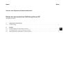
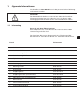
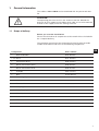
367
Anbauanleitung für Bausatz 0367 595144
Instructions for fitting for kit 0367 595144
Pneumatische Fußlüftung
D
Sewing foot lift with pedal
GB
Postfach 17 03 51, D-33703 Bielefeld • Potsdamer Straße 190, D-33719 Bielefeld
Telefon +49 (0) 5 21 / 9 25-00 • Telefax +49 (0) 5 21 / 9 25 24 35 • www.duerkopp-adler.com
Ausgabe / Edition:
04/2010
Änderungsindex
Rev. index: 01.0
Printed in Federal Republic of Germany
Teile-Nr./Part.-No.:
0791 367704
Vorwort
Diese Anleitung soll erleichtern, die Maschine kennenzulernen und ihre
bestimmungsmäßigen Einsatzmöglichkeiten zu nutzen.
Die Betriebsanleitung enthält wichtige Hinweise, die Maschine sicher,
sachgerecht und wirtschaftlich zu betreiben. Ihre Beachtung hilft,
Gefahren zu vermeiden, Reparaturkosten und Ausfallzeiten zu
vermindern und die Zuverlässigkeit und die Lebensdauer der Maschine
zu erhöhen.
Die Betriebsanleitung ist geeignet, Anweisungen aufgrund bestehender
nationaler Vorschriften zur Unfallverhütung und zum Umweltschutz zu
ergänzen.
Die Betriebsanleitung muß ständig am Einsatzort der Maschine/Anlage
verfügbar sein.
Die Betriebsanleitung ist von jeder Person zu lesen und anzuwenden,
die beauftragt ist, an der Maschine/Anlage zu arbeiten. Darunter ist zu
verstehen:
–
–
–
Bedienung, einschließlich Rüsten, Störungsbehebung im
Arbeitsablauf, Beseitigung von Produktionsabfällen, Pflege,
Instandhaltung (Wartung, Inspektion, Instandsetzung) und/oder
Transport
Der Bediener hat mit dafür zu sorgen, daß nur autorisierte Personen an
der Maschine arbeiten.
Der Bediener ist verpflichtet, die Maschine mindestens einmal pro
Schicht auf äußerlich erkennbare Schäden und Mängel zu prüfen,
eingetretene Veränderungen (einschließlich des Betriebsverhaltens),
die die Sicherheit beeinträchtigen, sofort zu melden.
Das verwendende Unternehmen hat dafür zu sorgen, daß die Maschine
immer nur in einwandfreiem Zustand betrieben wird.
Es dürfen grundsätzlich keine Sicherheitseinrichtungen demontiert oder
außer Betrieb gesetzt werden.
Ist die Demontage von Sicherheitseinrichtungen beim Rüsten,
Reparieren oder Warten erforderlich, hat unmittelbar nach Abschluß
der Wartungs- oder Reparaturarbeiten die Remontage der
Sicherheitseinrichtungen zu erfolgen.
Eigenmächtige Veränderungen an der Maschine schließen eine
Haftung des Herstellers für daraus resultierende Schäden aus.
Alle Sicherheits- und Gefahrenhinweise an der Maschine/Anlage
beachten! Die gelb/schwarz gestreiften Flächen sind Kennzeichnungen
ständiger Gefahrenstellen, z. B. mit Quetsch-, Schneid-, Scher- oder
Stoßgefahr.
Beachten Sie neben den Hinweisen in dieser Betriebsanleitung die
allgemein gültigen Sicherheits- und Unfallverhütungs-Vorschriften.
Allgemeine Sicherheitshinweise
Die Nichteinhaltung folgender Sicherheitshinweise kann zu körperlichen
Verletzungen oder zu Beschädigungen der Maschine führen.
1. Die Maschine darf erst nach Kenntnisnahme der zugehörigen
Betriebsanleitung und nur durch entsprechend unterwiesene
Bedienpersonen in Betrieb genommen werden.
2. Lesen Sie vor Inbetriebnahme auch die Sicherheitshinweise und die
Betriebsanleitung des Motorsherstellers.
3. Die Maschine darf nur ihrer Bestimmung gemäß und nicht ohne die
zugehörigen Schutzeinrichtungen betrieben werden; dabei sind
auch alle einschlägigen Sicherheitsvorschriften zu beachten.
4. Beim Austausch von Nähwerkzeugen (wie z.B. Nadel, Nähfuß,
Stichplatte, Stoffschieber und Spule), beim Einfädeln, beim
Verlassen des Arbeitsplatzes sowie bei Wartungsarbeiten ist die
Maschine durch Betätigen des Hauptschalters oder durch
Herausziehen des Netzsteckers vom Netz zu trennen.
5. Die täglichen Wartungsarbeiten dürfen nur von entsprechend
unterwiesenen Personen durchgeführt werden.
6. Reparaturarbeiten sowie spezielle Wartungsarbeiten dürfen nur von
Fachkräften bzw. entsprechend unterwiesenen Personen
durchgeführt werden.
7. Für Wartungs- und Reparaturarbeiten an pneumatischen
Einrichtungen ist die Maschine vom pneumatischen
Versorgungsnetz (max. 7 - 10 bar) zu trennen.
Vor dem Trennen ist zunächst eine Druckentlastung an der
Wartungseinheit vornehmen.
Ausnahmen sind nur bei Justierarbeiten und Funktionsprüfungen
durch entsprechend unterwiesene Fachkräfte zulässig.
8. Arbeiten an der elektrischen Ausrüstung dürfen nur von dafür
qualifizierten Fachkräften durchgeführt werden.
9. Arbeiten an unter Spannung stehenden Teilen und Einrichtungen
sind nicht zulässig.
Ausnahmen regeln die Vorschriften DIN VDE 0105.
10. Umbauten bzw. Veränderungen der Maschine dürfen nur unter
Beachtung aller einschlägigen Sicherheitsvorschriften
vorgenommen werden.
11. Bei Reparaturen sind die von uns zur Verwendung freigegebenen
Ersatzteile zu verwenden.
12. Die Inbetriebnahme des Oberteils ist so lange untersagt, bis
festgestellt wurde, dass die gesamt Näheinheit den
Bestimmungen der EG-Richtlinien entspricht.
13. Das Anschlusskabel muss mit einem landesspezifischen
zugelassenem Netzstecker versehen werden. Hierfür ist eine
qualifizierte Fachkraft erforderlich (sh. auch Pkt. 8).
Diese Zeichen stehen vor Sicherheitshinweisen,
die unbedingt zu befolgen sind.
Verletzungsgefahr !
Beachten Sie darüber hinaus
auch die allgemeinen Sicherheitshinweise.
Inhalt
Seite:
Vorwort und allgemeine Sicherheitshinweise
Einbau der pneumatischen Fußlüftung Klasse 367
(Ausgabe 04.2010)
1.
Allgemeine Information
1.1
Lieferumfang . . . . . . . . . . . . . . . . . . . . . . . . . . . . . . . . . . . . . . . . . . . . . . . . . .
3
2.
2.1
2.2
2.3
Einbau
Schubstange durch Zylinder ersetzen . . . . . . . . . . . . . . . . . . . . . . . . . . . . . . . . . .
Gestänge durch neues Gestänge ersetzen . . . . . . . . . . . . . . . . . . . . . . . . . . . . . . . .
Wartungseinheit anbringen und anschließen . . . . . . . . . . . . . . . . . . . . . . . . . . . . . .
4
6
7
D
1.
Allgemeine Informationen
Die Unterklasse 367-170010 kann mit der pneumatischen Fußlüftung
nachgerüstet werden.
ACHTUNG!
Der Betriebsdruck der Klasse 367 ist 6 bar. Sollte der Druck Ihrer
Versorgungsleitung höher als 6 bar sein, muss der Druck an der
Versorgungseinheit der Nähmaschine auf 6 bar reduziert werden!
1.1 Lieferumfang
Bevor Sie mit dem Einbau beginnen:
Bitte überprüfen Sie, ob alle Bauteile des Nachrüstsatzes in dem
Lieferumfang enthalten sind.
Der komplette Bausatz für die pneumatische Fußlüftung mit der
Bestellnummer: 0367 595144 besteht aus folgenden Komponenten:
Bauteil
Teilenummer
1
9780 982005
Schalldämpfer
1,3 m Schlauch
9731 005004
1
Verbindung WI-N
9790 010010
2
Verschraubung GD-E
9790 200001
1
Verschraubung WI-E
9790 201001
1
Zylinder
0367 135174
1
Gestänge
Z 100 000343
1
Befestigungsschelle
9840 120026
1
Wartungseinheit
9780 000108
1
Druckleitung
0797 003031
1
Kupplungsdose
0744 001793 A
1
Kupplungsstecker (an Druckleitung)
0744 001793 B
2
Ideal-Schelle (1x an Druckleitung)
0742 002096
1
Schlauchtülle
0744 001796
1
Innensechskantschraube
9202 002077
1
Pneumatik-Geräteplan
9770 367503
D
3
2.
Einbau
Vorsicht Verletzungsgefahr!
Schalten Sie den Hauptschalter aus und ziehen Sie den Netzstecker,
bevor sie mit dem Einbau der pneumatischen Fußlüftung beginnen.
Der Einbau darf nur von qualifizierten Technikern durchgeführt
werden.
–
–
Kippen Sie die Nähmaschine nach hinten ab.
Lösen Sie die 6 Schrauben der Ölwanne und nehmen Sie die
Ölwanne ab.
2.1 Schubstange durch Zylinder ersetzen
1
7
4
2
8
1
3
4
5
3
6
–
Entfernen Sie an der Schubstange 2 rechts die
Sicherungsscheibe 3 und links die Schraube 1.
–
Ziehen Sie die Schubstange 2 rechts von dem Zapfen.
–
Führen Sie den Schlauch 6 durch die Halterung 5 an der
Maschinenrückwand.
–
Schieben Sie den Schlauch 6 auf den Anschluss 8 des Zylinders 4.
–
Bauen Sie den Zylinder 4 an Stelle der Schubstange 2 ein. Der
Kolben muss dabei nach rechts zeigen und die Drosselschraube 7
muss nach unten zeigen.
Drehen Sie die Drosselschraube 7 gegen den Uhrzeigersinn,
bewegt sich der Kolben schneller. Der Nähfuß wird schneller
gelüftet.
Drehen Sie die Drosselschraube 7 im Uhrzeigersinn, bewegt sich
der Kolben langsamer. Der Nähfuß wird langsamer gelüftet.
–
Setzen Sie an dem Zylinder 4 rechts die Sicherungsscheibe 3
wieder auf und drehen sie links die Schraube 1 wieder ein.
–
Führen Sie den Schlauch 6 an der Maschinenrückwand nach
rechts. Führen Sie den Schlauch durch die Ausfräsung 9 rechts
unten an der Nähmaschine nach außen.
6
9
10
11
12
–
Mit der Verbindung WI-N 12 müssen Sie jetzt den Schlauch nach
unten führen.
–
Stecken Sie dazu die Befestigungsschelle 10 auf den Schlauch 6.
Um die Länge des Schlauches 6 abzumessen, halten Sie die
Befestigungsschelle 10 an die Bohrung rechts unten an der
Nähmaschine.
Schneiden Sie den Schlauch 6 hinter der Befestigungsschelle 10
ab.
–
Verbinden Sie die Schlauchenden mit der Verbindung WI-N 12.
–
Schrauben Sie den Schlauch 6 mit der Befestigungsschelle 10,
direkt an der Verbindung WI-N 12 mit der Innensechskantschraube 11, an die Bohrung rechts unten an der Nähmaschine.
Führen Sie das lose Schlauchende unter das Untergestell.
Setzen Sie die Ölwanne auf und ziehen Sie die 6 Schrauben an.
Kippen Sie die Nähmaschine wieder nach vorn.
–
–
D
Hinweise
Sollten Sie die Nähleuchte 9822 510001 eingebaut haben, werden
sowohl der Schlauch als auch das Kabel der Beleuchtung an die
Bohrung rechts unten an der Nähmaschine angeschraubt.
Die im Lieferumfang enthaltene Innensechskantschraube 11 ist
lang genug, um 2 Befestigungsschellen anzuschrauben.
5
2.2 Gestänge durch neues Gestänge ersetzen
1
6
2 3
4
5
6
7
–
Schrauben Sie in die obere Bohrung den Schalldämpfer 7 ein.
Schrauben Sie in die beiden anderen Bohrungen die
Verschraubungen GD-E 5 und 6 ein. Ziehen Sie die
Verschraubungen 5 und 6 an, damit die Gewinde mit der
aufgetragenen Dichtungsmasse richtig abdichtet werden.
–
Entfernen Sie die Muttern des alten Gestänges an dem Pedal 1
und an dem Antrieb 4. Entfernen Sie das alte Gestänge.
–
Bauen Sie an Stelle des alten Gestänges das neue Gestänge 3 ein.
Stecken Sie die Unterlegscheiben auf und schrauben Sie die
Muttern 1 und 4 wieder auf.
–
Um die Position des Pedals anzupassen, lösen Sie die Schraube 2
Stellen Sie das Pedal passend ein und ziehen Sie die Schraube 2
wieder an.
2.3 Wartungseinheit anbringen und anschließen
8
5
6
12 13
9
D
9
–
Schrauben Sie die Schlauchtülle 10 in den würfelförmigen
Anschluss 12 der Wartungseinheit 13.
–
Entfernen Sie das Verbindungsstück 8 mit den Dichtungsscheiben
aus der Wartungseinheit 13 und ersetzen Sie es durch die
Verschraubung WI-E 9.
–
Schrauben Sie die Wartungseinheit 13 so an das Untergestell,
dass der Wasserabscheider möglichst senkrecht nach unten zeigt.
Haben Sie das Untergestell MG 55-3, bringen Sie die Wartungseinheit 13 an die Querstange rechts unterhalb des Antriebs an.
Führen Sie den aus der Nähmaschine kommenden Schlauch zu
dem neuen Gestänge 3. Schneiden Sie den Schlauch so ab, dass
er nicht spannt und stecken Sie ihn in die Verschraubung GD-E 6.
Verbinden Sie mit dem restlichen Schlauch die Verschraubung
GD-E 5 mit der Verschraubung WI-E 9 an der Wartungseinheit.
–
–
10
11
–
Schrauben Sie die Kupplungsdose 11 an Ihre Druckversorgung.
–
Stecken Sie die Ideal-Schelle 15 auf die Druckleitung 16. Schieben
Sie dann die Druckleitung 16 auf die Schlauchtülle 10 an der
Wartungseinheit 13. Sichern Sie mit der Ideal-Schelle 15 die
Druckleitung auf dem Anschlussstück 10.
–
Stecken Sie die Druckleitung 16 mit dem Kupplungsstecker 14 in
die Kupplungsdose 11 an Ihrer Druckversorgung.
14
15
16
ACHTUNG!
Der Betriebsdruck ist 6 bar. Kontrollieren Sie an der Wartungseinheit,
ob 6 bar angezeigt werden! Wenn nötig regeln Sie den Druck an der
Wartungseinheit auf 6 bar bevor Sie die pneumatische Fußlüftung
betätigen.
7
Für Ihre Notizen:
8
Foreword
This instruction manual is intended to help the user to become familiar
with the machine and take advantage of its application possibilities in
accordance with the recommendations.
The instruction manual contains important information on how to
operate the machine securely, properly and economically. Observation
of the instructions eliminates danger, reduces costs for repair and
down-times, and increases the reliability and life of the machine.
The instruction manual is intended to complement existing national
accident prevention and environment protection regulations.
The instruction manual must always be available at the machine/sewing
unit.
The instruction manual must be read and applied by any person that is
authorized to work on the machine/sewing unit. This means:
–
–
–
Operation, including equipping, troubleshooting during the work
cycle, removing of fabric waste,
Service (maintenance, inspection, repair) and/or
Transport.
The user also has to assure that only authorized personnel work on the
machine.
The user is obliged to check the machine at least once per shift for
apparent damages and to immediatly report any changes (including the
performance in service), which impair the safety.
The user company must ensure that the machine is only operated in
perfect working order.
Never remove or disable any safety devices.
If safety devices need to be removed for equipping, repairing or
maintaining, the safety devices must be remounted directly after
completion of the maintenance and repair work.
Unauthorized modification of the machine rules out liability of the
manufacturer for damage resulting from this.
Observe all safety and danger recommendations on the machine/unit!
The yellow-and-black striped surfaces designate permanend danger
areas, eg danger of squashing, cutting, shearing or collision.
Besides the recommendations in this instruction manual also observe
the general safety and accident prevention regulations!
General safety instructions
The non-observance of the following safety instructions can cause
bodily injuries or damages to the machine.
1. The machine must only be commissioned in full knowledge of the
instruction book and operated by persons with appropriate training.
2. Before putting into service also read the safety rules and
instructions of the motor supplier.
3. The machine must be used only for the purpose intended. Use of
the machine without the safety devices is not permitted. Observe all
the relevant safety regulations.
4. When gauge parts are exchanged (e.g. needle, presser foot, needle
plate, feed dog and bobbin) when threading, when the workplace is
left, and during service work, the machine must be disconnected
from the mains by switching off the master switch or disconnecting
the mains plug.
5. Daily servicing work must be carried out only by appropriately
trained persons.
6. Repairs, conversion and special maintenance work must only be
carried out by technicians or persons with appropriate training.
7. For service or repair work on pneumatic systems, disconnect the
machine from the compressed air supply system (max. 7-10 bar).
Before disconnecting, reduce the pressure of the maintenance unit.
Exceptions to this are only adjustments and functions checks made
by appropriately trained technicians.
8. Work on the electrical equipment must be carried out only by
electricians or appropriately trained persons.
9. Work on parts and systems under electric current is not permitted,
except as specified in regulations DIN VDE 0105.
10. Conversion or changes to the machine must be authorized by us
and made only in adherence to all safety regulations.
11. For repairs, only replacement parts approved by us must be used.
12. Commissioning of the sewing head is prohibited until such time as
the entire sewing unit is found to comply with EC directives.
13. The line cord should be equipped with a country-specific mains
plug. This work must be carried out by appropriately trained
technicians (see paragraph 8).
It is absolutely necessary to respect the safety
instructions marked by these signs.
Danger of bodily injuries !
Please note also the general safety instructions.
Index
Page:
Preface and general safety hints
Fitting the pneumatic foot lift class 367
(Edition 04/2010)
1.
General information
1.1
Scope of delivery . . . . . . . . . . . . . . . . . . . . . . . . . . . . . . . . . . . . . . . . . . . . . . .
3
2.
2.1
2.2
2.3
Fitting
Replace the slide bar by a cylinder . . . . . . . . . . . . . . . . . . . . . . . . . . . . . . . . . . . .
Replace bars by new bars . . . . . . . . . . . . . . . . . . . . . . . . . . . . . . . . . . . . . . . . . .
Fit and connect maintenance unit . . . . . . . . . . . . . . . . . . . . . . . . . . . . . . . . . . . . .
4
6
7
GB
1.
General information
The subclass 367-170010 can be retrofitted with the pneumatic foot
lift.
ATTENTION!
The operating pressure of class 367 amounts to 6 bar. Should the
pressure of your supply line be higher than 6 bar, it has to be reduced
to 6 bar at the supply unit of the sewing machine!
1.1 Scope of delivery
Before you start the installation:
Please check whether all components of the retrofit kit are included in
the scope of delivery.
The complete mounting kit for the pneumatic foot lift with the order
number 0367 595144 consists of the following components:
Component
Parts number
1
9780 982005
Sound absorber
1.3 m Hose
9731 005004
1
Connection WI-N
9790 010010
2
Screw connection GD-E
9790 200001
1
Screw connection WI-E
9790 201001
1
Cylinder
0367 135174
1
Bars
Z 100 000343
1
Fastening clip
9840 120026
1
Maintenance unit
9780 000108
1
Pressure line
0797 003031
1
Coupling box
0744 001793 A
1
Coupling plug (at the pressure line)
0744 001793 B
2
Ideal clip (1x at the pressure line)
0742 002096
1
Hose nozzle
0744 001796
1
Allen screw
9202 002077
1
Pneumatic device plan
9770 367503
GB
3
2.
Fitting
Caution: Danger of injury!
Switch off the main switch and pull out the mains plug before you
start to install the pneumatic foot lift. The installation must be done
by qualified technicians only.
–
–
Tilt the sewing machine to the back.
Loosen the 6 screws of the oil pan and take the oil pan off.
2.1 Replace the slide bar by a cylinder
1
7
4
2
1
3
4
5
3
6
–
Remove the locking washer 3from the right end of the slide bar 2
and the screw 1 from the left end of the slide bar 2.
–
Remove the slide bar 2 from the finger on the right.
–
Run the hose 6 through the fixture 5 at the rear panel of the
machine.
–
Push the hose 6 on the connection 8 of the cylinder 4.
–
Fit the cylinder 4 instead of the slide bar 2. The piston must show
to the right and the throttling screw 7 must show down.
If you turn the throttling screw 7 counter-clockwise, the piston is
moving more quickly. The sewing foot is lifted more quickly.
If you turn the throttling screw 7 in clockwise direction, the piston
is moving more slowly. The sewing foot is lifted more slowly.
–
Put the locking washer 3 on the right of the cylinder 4 again and
screw in screw 1 on the left again.
–
Run the hose 6 to the right at the rear panel of the machine. Run
the hose outside through the cut-out 9 down on the right of the
sewing machine.
8
6
9
10
11
12
–
Now you have to guide the hose downward with the connection
WI-N 12.
–
For this purpose put the fastening clip 10 on the hose 6. In order
to measure the length of the hose 6, hold the fastening clip 10
close to the drill-hole down on the right of the sewing machine.
Cut the hose 6 off behind the fastening clip 10.
–
Connect the hose ends with the connection WI-N 12.
–
Screw the hose 6 with the fastening clip 10 (directly at the
connection WI-N 12 with the Allen screw 11) on the drill-hole down
on the right of the sewing machine.
Guide the loose end of the hose underneath the stand.
Put the oil pan on and tighten the 6 screws.
Tilt the sewing machine to the front again.
–
–
GB
Hints
In case you have installed the sewing light 9822 510001, not only
the hose but also the cable of the lighting are screwed on the
drill-hole down on the right of the sewing machine.
The Allen screw 11 included in the accessories is long enough to
tighten 2 fastening clips.
5
2.2 Replace bars by new bars
1
6
2 3
4
5
6
7
–
Screw the sound absorber 7 in the upper drill-hole. Screw the
screw connections GD-E 5 and 6 in the other two drill-holes.
Tighten the screw connections 5 and 6 so that the threads are
correctly sealed by the applied sealing compound.
–
Remove the nuts of the old bars at pedal 1 and drive 4. Remove
the old bars.
–
Fit the new bars 3 instead of the old bars. Put on the washers and
screw on the nuts 1 and 4 again.
–
Loosen screw 2 in order to adjust the position of the pedal. Adjust
the pedal to fit and tighten the screw 2 again.
2.3 Fit and connect the maintenance unit
8
5
9
Screw the hose nozzle 10 in the cubical-shaped connection 12 of
the maintenance unit 13.
–
Remove the connecting piece 8 with the washers from the
maintenance unit 13 and replace it by the screw connection
WI-E 9.
–
Screw the maintenance unit 13 on the stand in such a way that the
water separator shows downward in a vertical direction. If you
have got the stand MG 55-3, fit the maintenance unit 13 at the
cross bar on the right beneath the drive.
Guide the hose coming out of the sewing machine to the new
bars 3. Cut the hose off in such a way that it is not under tension
and push it into the screw connection GD-E 6.
–
11
12 13
–
9
10
6
GB
–
Connect the screw connection GD-E 5 and the screw connection
WI-E 9 at the maintenance unit with the remaining hose.
–
Screw the coupling box 11 on your pressure supply.
–
Put the Ideal clip 15 on the pressure line 16. Then push the
pressure line 16 on the hose nozzle 10 at the maintenance unit 13.
Secure the pressure line on the connection piece 10 by the Ideal
clip 15.
–
Plug the coupling plug 14 of the pressure line 16 in the coupling
box 11 of your pressure supply.
14
15
16
ATTENTION!
The operating pressure amounts to 6 bar. Check at the maintenance
unit whether 6 bar is indicated!
If necessary, adjust the pressure at the maintenance unit to 6 bar
before actuating the pneumatic foot lift.
7
Your own notes:
8