1
USER NOTICES
The notices on this brewer should be kept in good condition. Replace unreadable or damaged labels.
00831.0000
ELECTRICAL REQUIREMENTS
CAUTION - Do not connect to the power source until specified in Initial Set-Up.
This equipment requires either 2-wire, grounded service rated 120 volts ac or 3-wire, grounded service rated 120/
208 or 120/240 volts ac, 20 amp, single phase, 60 Hz. Refer to the product data plates on the brewer and grinder for
actual voltage of your particular model.
CAUTION – Improper electrical installation will damage electronic components.
1.
2.
3.
4.
5.
6.
7.
8.
An electrician must provide electrical service as specified.
Remove the brewer top lid held in place with one screw. Lift the front of the lid slightly and push it back.
Remove the restraining device from the swing-away coffee chute. it will swing to a vertical position when freed.
(1-hopper grinder) Remove the screw below the grinder's front decal. Tilt the grinder back on the top lid and set
the screw aside for later installation.
(2-hopper grinder) Remove the front inspection panel on the grinder. Set it aside for later installation.
Set the grinder on top of the brewer sliding it to interconnect the tab with its mating slot.
Plug the grinder's polarized six-pin electrical connector into its mate at the top of the brewer.
Install the screw to secure the front of the grinder to the brewer.
(1-hopper grinder) Tilt the grinder forward over the hood front.
NOTE – The swing away coffee chute mechanism must not get jammed. It must be in front of the movable sprayhead
mechanism. Move the sprayhead mechanism out of the way if necessary by pushing the threaded rod to either side
of the hood and then pushing the bracket until it is as far back as possible.
8. Place the switch on the rear of brewer in the “OFF” (lower) position.
9. Remove the front panel of the brewer. Set it aside for later installation.
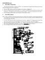
10. Place the heater switch at the bottom of the Digital Brewer Control (DBC) , the box on the top of the component
mounting bracket, in the “OFF” (left) position.
11. Feed the cord through the strain relief at the rear of the brewer and connect it to the terminal block.
12. Using a voltmeter, check the voltage and color coding of each conductor at the power source.
13. Connect the brewer to the power source, verify the voltage at the terminal block and reinstall the brewer front panel.
WARNING – The brewer must be electrically grounded using the green screw near the terminal block. Do not assume
a plumbing line will provide an adequate ground.
14. If plumbing is to be hooked-up later be sure the brewer is disconnected from the power source. If plumbing has
been hooked-up, the brewer is ready for Initial Set-Up.
2